

Page 1

volkswagen :: Volkswagen Beetle L4-2.0L (AEG) (
2000)
Page 2
> Relays and Modules > Relays and Modules - Accessories and Optional Equipment > Alarm Horn Relay > Component Information > Locations
Alarm Horn Relay: Locations
RELAY LOCATIONS
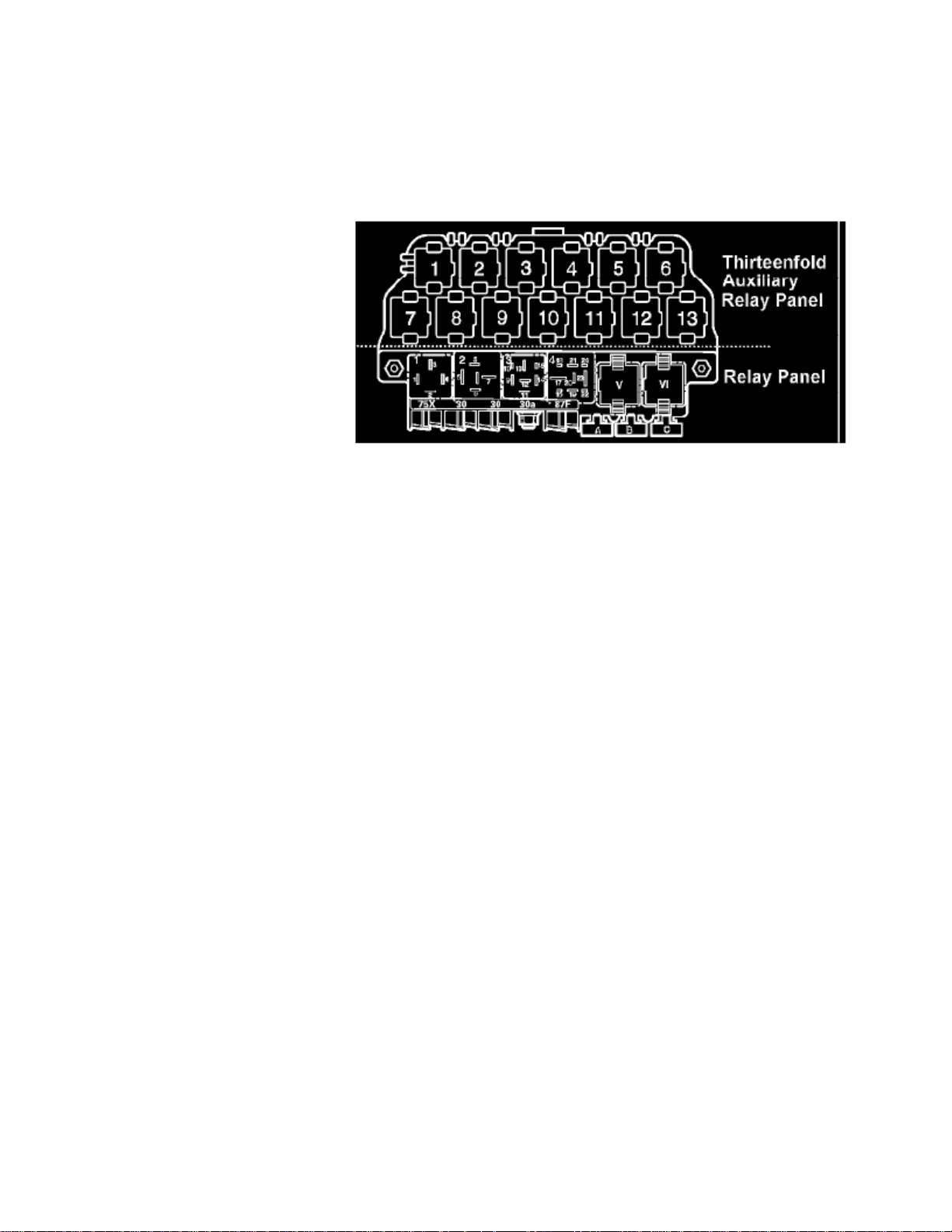
Relay Panel & Thirteenfold Auxiliary Relay Panel
Relay location on the thirteen position auxiliary relay panel, above relay panel:
1 - Alarm System Light Flasher Relay (404)
2 - Alarm System Light Flasher Relay (200)
3 - Back-up Light Relay (53)
3 - Lock Relay for Starter (Theft Warning System) (185)
4 - Lock Relay for Starter (Clutch pedal Switch) (53)
7 - Daytime Running Lights Change-over Relay (173)
8 - Daytime Running Lights Change-over Relay (173)
8 - Heated Exterior Mirror Relay (53)
9 - Alarm Horn Relay (53)
10 - Glow Plug Relay (180)
10 -
Third Speed Coolant Fan Control (FC) Relay (100)*
11 - Park/Neutral Position (PNP) Relay (126) (175)
12 - Power Supply (Terminal 30, B+) Relay (109)
Only applies to 1.8L turbo engines*
Relay panel:
1 - Dual Horn Relay (53)
2 - Load Reduction Relay (18) (100) (213)
4 - Fuel Pump (FP) Relay (409)
V - Wiper/Washer Intermittent Relay (192) (377) (389)
VI - Wiper/Washer Intermittent Relay (192) (377) (389)
Number in parentheses ( ) indicates production control number stamped on relay housing.NOTE
Page 3

Page 4

> Relays and Modules > Relays and Modules - Accessories and Optional Equipment > Antenna Control Module > Component Information > Technical Service Bulletins > Customer Interest for Antenna Control Module: > 9105-
01 > May > 05 > Audio System - Poor Radio Reception
Technical Service Bulletin # 9105-01
Audio System - Poor Radio Reception
Group: 91
Number: 05-01
Date: May 2, 2005
Subject: Radio, Reception Diagnosis
Model(s): All with Premium V and VI Radio
1998 > 2006
Condition
Poor radio reception.
Service Procedure
For concerns of poor radio reception:
- Use the following as a guide for trouble shooting.
Tip:
This Technical Bulletin is divided into four sections:
^ Section 1: Includes antenna systems by vehicle.
^ Section 2: Includes radio antenna system diagnosis procedures for AM/FM concerns using internal radio diagnostics.
^ Section 3: Includes antenna lead diagnosis.
^ Section 4: Antenna cables
Tip:
^ Perceived reception issues may be a result of environmental factors.
^ Reception may be diminished in certain areas due to power wires, buildings and/or overpasses.
^ Aftermarket window tint may interfere with reception.
^ In cases that are questionable, locate identical vehicle and verify concern (if the like vehicle is same, condition may be normal).
Section 1 - Antenna systems by vehicle
Tip:
For more detail see Repair Manual Group 91- Communication of the vehicle you are working on.
Passat (W8 only)
Page 5

> Relays and Modules > Relays and Modules - Accessories and Optional Equipment > Antenna Control Module > Component Information > Technical Service Bulletins >
Customer Interest for Antenna Control Module: > 9105-01 > May > 05 > Audio System - Poor Radio Reception > Page 15
Beetle L4-2.0L (AEG) (2000)
Page 6
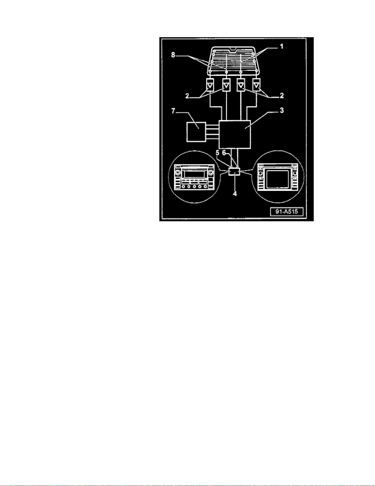
- Antenna Selection Control Module -J515- (Diversity box) -3-:
^ Location Wagon; behind left luggage compartment side trim, below rear side window.
^ Location, Sedan: under rear parcel shelf.
Antennas:
All models use four antennas -1-, -8-.
^ Location Wagon: Integrated with rear side windows.
^ Location Sedan: Integrated with rear window.
Antenna amplifiers:
All models use four antenna amplifiers -2-.
^ Location,Wagon: 2 each behind left and right luggage compartment side trim, below rear side windows.
^ Location Sedan: 2 under rear parcel shelf and 1 each behind left and right rear D-pillar trim.
Touareg
Page 7

> Relays and Modules > Relays and Modules - Accessories and Optional Equipment > Antenna Control Module > Component Information > Technical Service Bulletins >
Customer Interest for Antenna Control Module: > 9105-01 > May > 05 > Audio System - Poor Radio Reception > Page 16
Beetle L4-2.0L (AEG) (2000)
Page 8
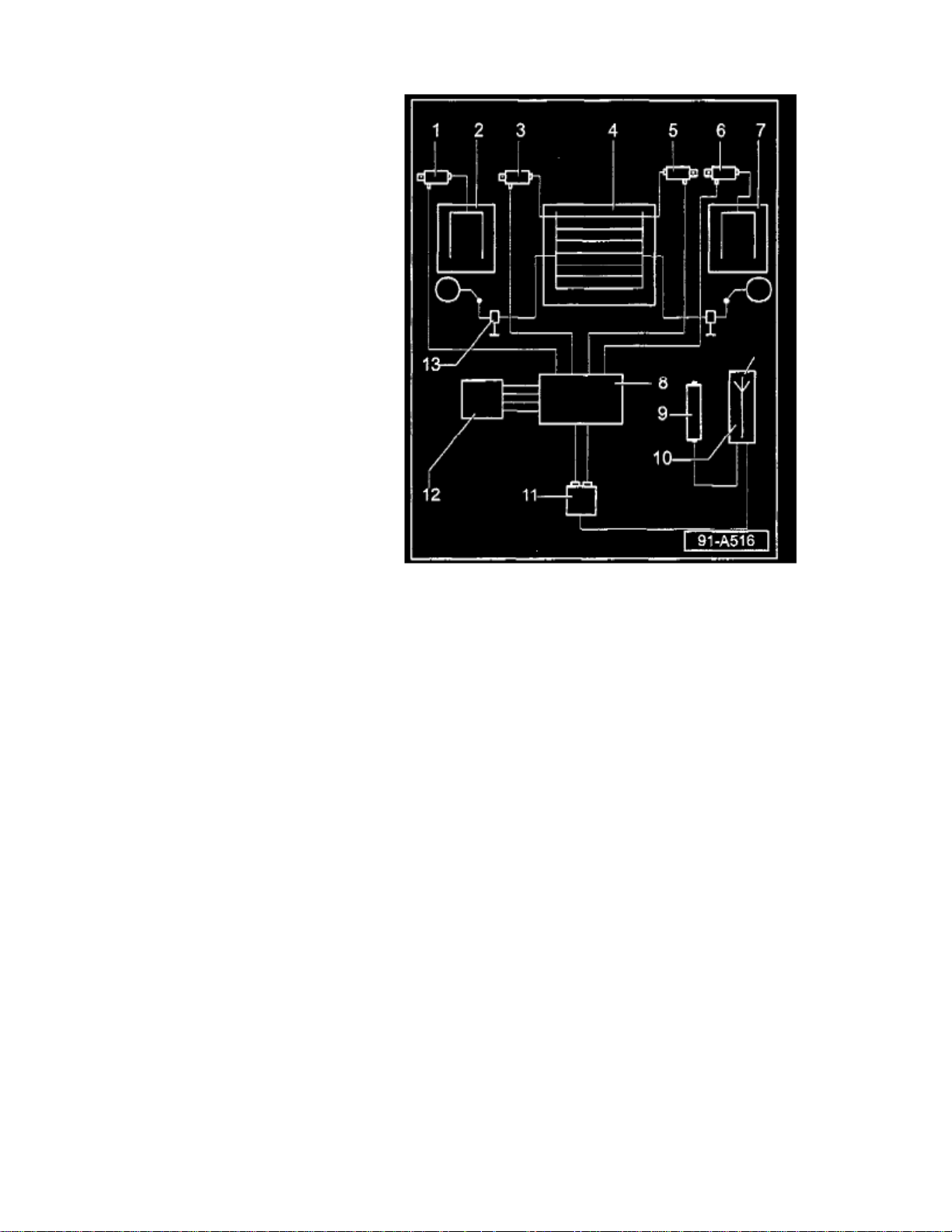
- Antenna Selection Control Module -J515- (Diversity box)
All models use an Antenna Selection Control Module -J515- item -8-.
^ Location: Behind rear section of molded headlining.
Antennas
All models use four antennas items -2-, 4- (qty. 2) & -7-.
^ Antennas (R130, R131) are integrated into rear hatch glass.
^ Antenna R11 in left rear side glass.
^ Antenna R93 in right rear side glass.
Antenna amplifiers
All models use four antenna amplifiers items -1-, -3-, -5- & -6-.
^ Item 1 - Antenna Amplifier 1 -R24- (for AM and FM reception). Above left side window.
^ Item 3 - Antenna Amplifier 2 -R111- (for FM reception). In upper section of rear lid.
^ Item 5 - Antenna Amplifier 3 -R112- (for FM reception). In upper section of rear lid.
^ Item 6 - Antenna Amplifier 4 -R113- (for FM reception). Above right side window.
Page 9

> Relays and Modules > Relays and Modules - Accessories and Optional Equipment > Antenna Control Module > Component Information > Technical Service Bulletins >
Customer Interest for Antenna Control Module: > 9105-01 > May > 05 > Audio System - Poor Radio Reception > Page 17
Beetle L4-2.0L (AEG) (2000)
Phaeton
Page 10
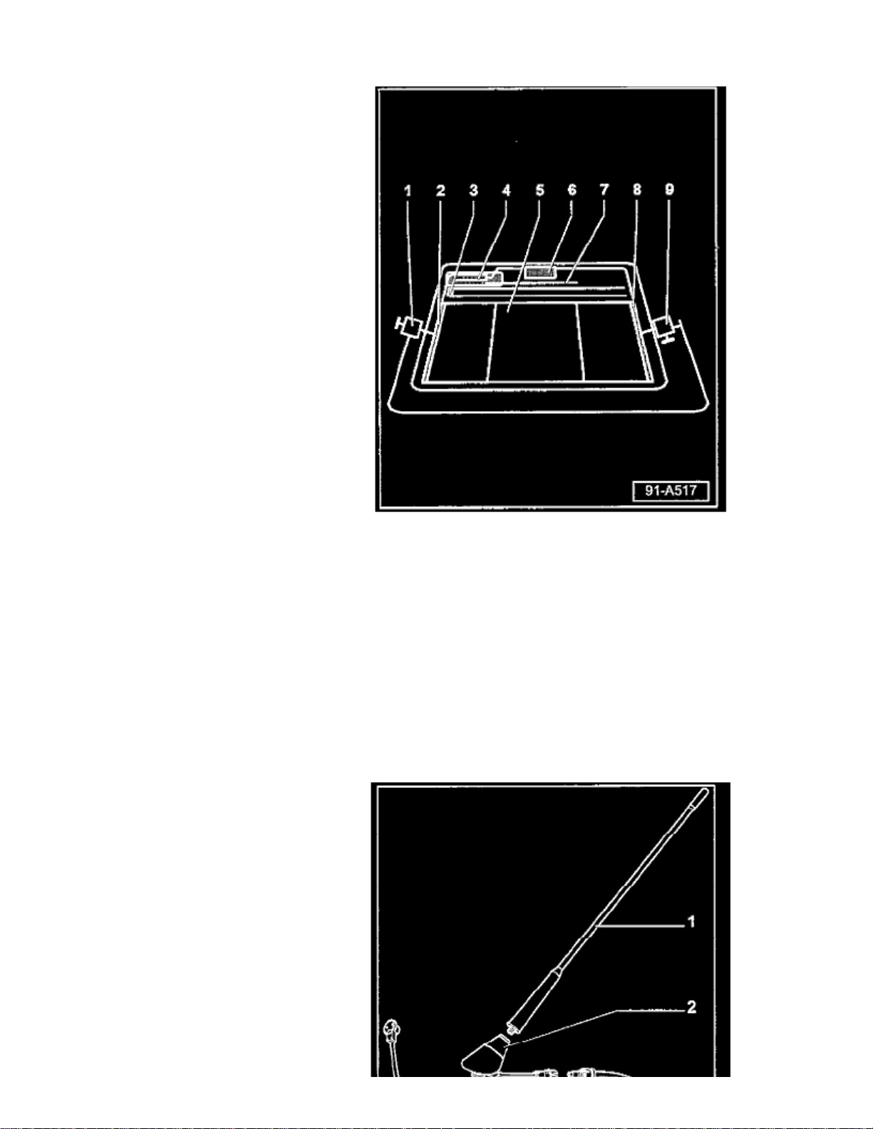
- Antenna Selection Control Module -J515- (Diversity box)
All models use an Antenna Selection Control Module -J515- item -4-.
^ Location: Above rear glass under headliner.
Antennas
All models use four antennas.
^ Antennas -2-, -7- and -8- (for FM reception). Integrated into rear glass -5^ Antenna -3- (for AM and FM reception). Integrated into rear glass -5-.
Page 11
> Relays and Modules > Relays and Modules - Accessories and Optional Equipment > Antenna Control Module > Component Information > Technical Service Bulletins >
Customer Interest for Antenna Control Module: > 9105-01 > May > 05 > Audio System - Poor Radio Reception > Page 18
Beetle L4-2.0L (AEG) (2000)
- Jetta / Golf / Passat (non W8) - Antenna system
^ All models use External amplified antenna mast -1-.
Page 12
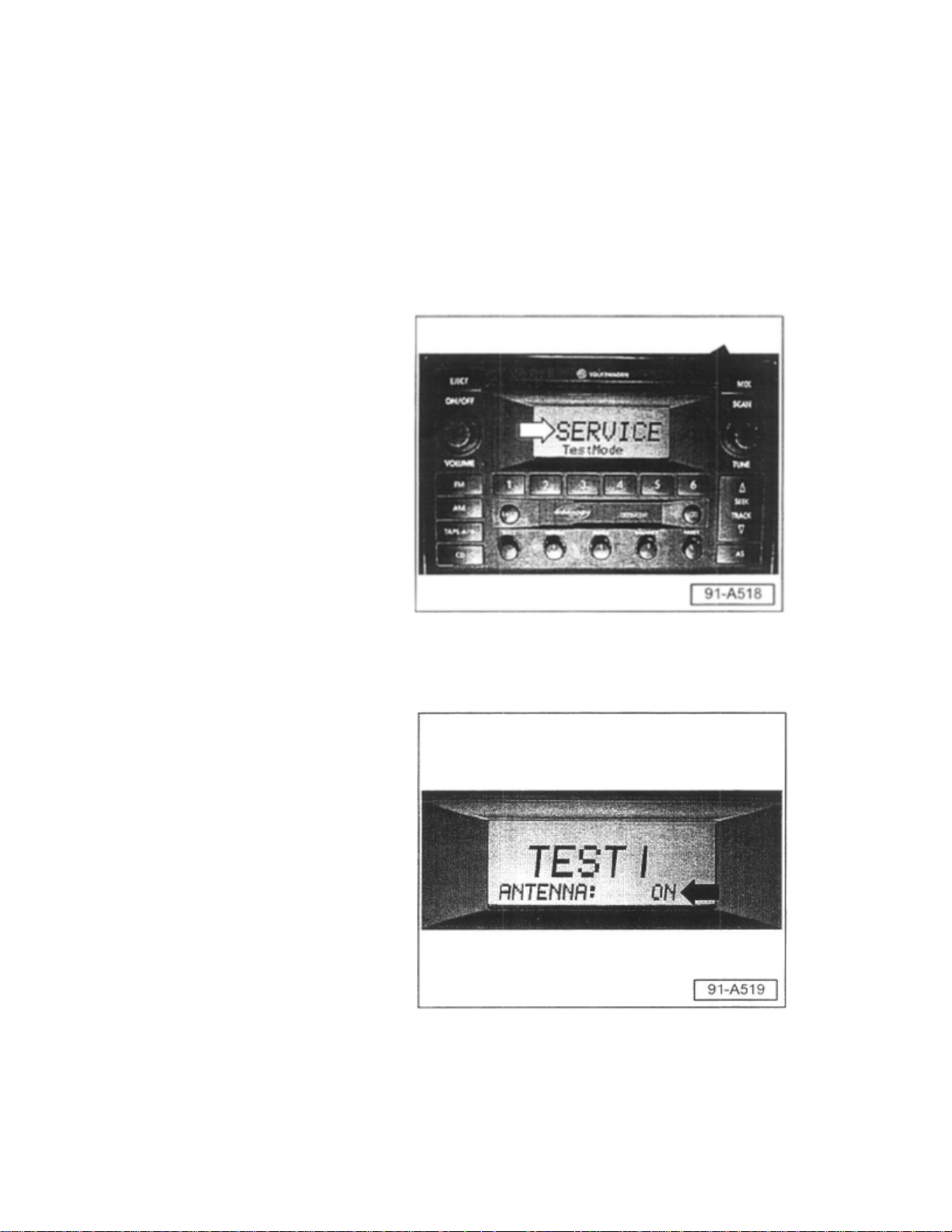
Section 2 - Radio antenna system diagnosis through radio unit
Premium VI radios are capable of signal diagnosis through operating internal diagnostics of the radio unit.
All models except Touareg and Phaeton:
- Select AM or FM.
- Press and hold the mix button (black arrow).
- Screen will appear that shows "Service Test mode" (white arrow).
- Press mix button briefly.
^ Test one indicates current antenna status, i.e. ON or OFF (arrow).
- Press mix button briefly again.
Page 13

> Relays and Modules > Relays and Modules - Accessories and Optional Equipment > Antenna Control Module > Component Information > Technical Service Bulletins >
Customer Interest for Antenna Control Module: > 9105-01 > May > 05 > Audio System - Poor Radio Reception > Page 19
Beetle L4-2.0L (AEG) (2000)
Page 14
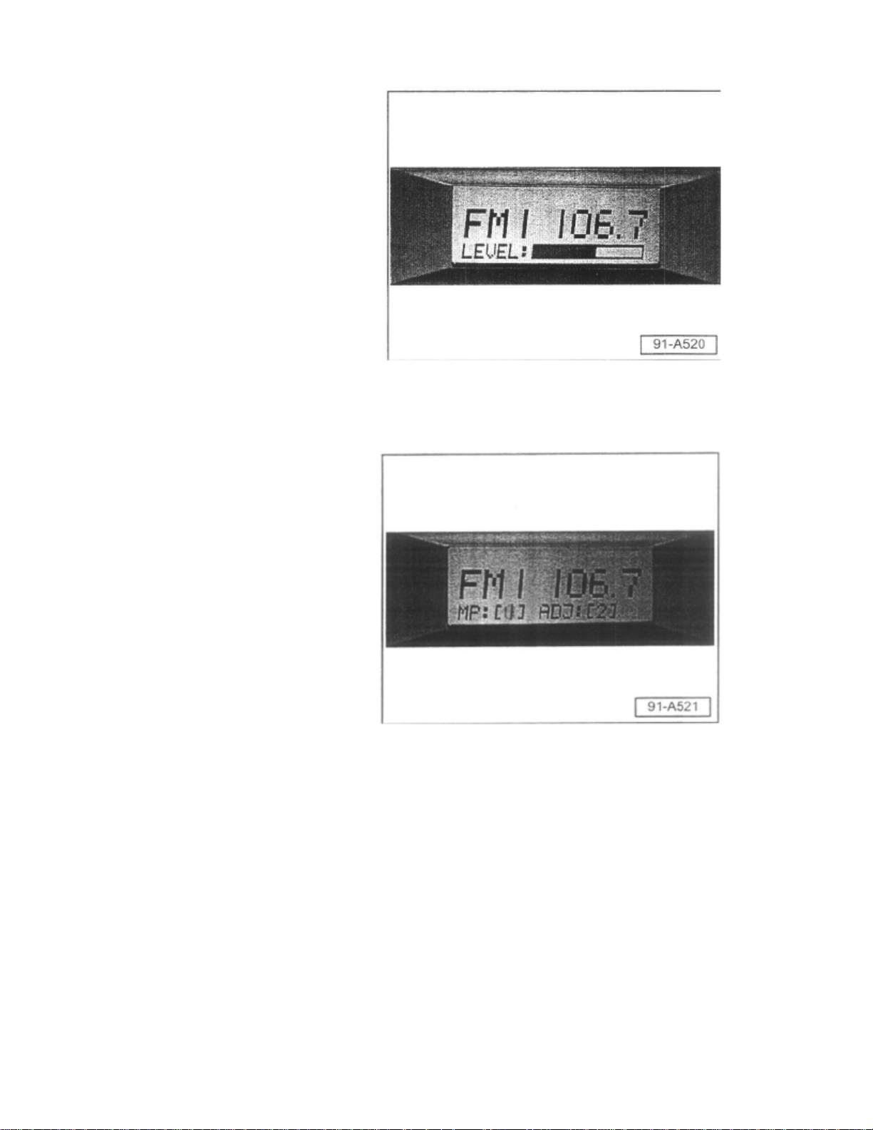
- Screen displays strength of signal (LEVEL) in bar graph form (can be used for AM and FM).
- Press mix button briefly again.
^ Screen indicates number of stations broadcasting close to frequency band of selected station.
^ As the number increases for [mp] and (adj], static and signal crossing will increase.
To exit service mode:
- Depress and hold the mix button or switch radio OFF then back ON
Navigation units
^ No internal diagnosis functions. Continue to antenna lead diagnosis.
Section 3 - Antenna Lead Diagnosis
After initial radio diagnosis using internal service functions, use the following procedures:
- Locate antenna lead/s from radio at system end-point, i.e. diversity box or antenna mast base.
Page 15

> Relays and Modules > Relays and Modules - Accessories and Optional Equipment > Antenna Control Module > Component Information > Technical Service Bulletins >
Customer Interest for Antenna Control Module: > 9105-01 > May > 05 > Audio System - Poor Radio Reception > Page 20
Beetle L4-2.0L (AEG) (2000)
- Check for proper connection. (follow steps for your type of system).
- For all systems, locate cable end-point at either diversity box or antenna mast base.
- Disconnect cable from either diversity box or antenna mast base.
- Carefully ground center wire in cable to chassis.
If reception returns:
^ Cable and radio are ok.
Page 16

If reception does not return:
^ Problem is located further forward in the system.
For problems forward of the antenna system:
- Continue with Section 3a.
For problems at antenna system:
Skip to Section 3b.
For problems at antenna systems:
Tip:
All checks should be done outdoors away from buildings.
Section 3a - Problems forward of antenna system
- First verify connection at Radio (check for bent or crushed connections and proper fit).
If all connections appear ok:
- Ground antenna lead at radio or attach external antenna mast to radio unit (check for reception).
If reception returns:
^ Problem is located between radio and antenna.
- Check connections near center console:
If connections are OK:
- Check resistance of cable from end to end.
^ If More than .4 ohms:
- Replace cable.
If reception does not return;
- Replace radio unit.
Section 3b - Problems at antenna system, Diversity Antenna (Touareg, Passat W8)
If concern is only AM poor / no reception;
Locate AM antenna amplifier.
^ Touareg: located above left side window.
Page 17

> Relays and Modules > Relays and Modules - Accessories and Optional Equipment > Antenna Control Module > Component Information > Technical Service Bulletins >
Customer Interest for Antenna Control Module: > 9105-01 > May > 05 > Audio System - Poor Radio Reception > Page 21
Beetle L4-2.0L (AEG) (2000)
^ Passat W8: Sedan above rear window.
^ Passat Wagon: located on left rear window.
- Check for proper connections at amplifier both from diversity box and to glass.
If connection issue is at glass or on glass:
- Glass must be replaced.
If connection problem to amplifier:
- Repair connection (replace cable or amplifier).
Page 18
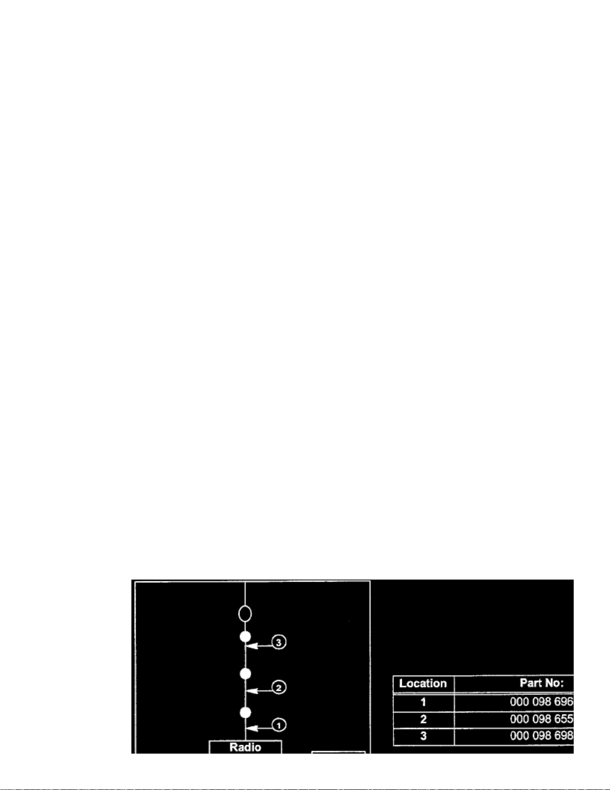
If no apparent connection problems:
- Replace amplifier.
If concern is poor FM reception:
- Disconnect all amplifiers, tune radio to high-powered station for your area.
- Connect amplifiers one at a time.
If reception is indicated:
- Disconnect that amplifier and move on to next amplifier.
If at any point in reconnecting amplifiers there is a loss in reception and there are no connection issues:
- Replace that amplifier and check again.
If there is no reception change when disconnecting and reconnecting all amplifiers:
- Replace diversity/antenna selection box.
Jetta / Golf / Passat (non W8) - Antenna system (Amplified Antenna Mast)
- Check connections at antenna base.
- Check for corrosion at mounting.
If corrosion is found:
- Clean mount and apply anti-seize gel to mounting.
If concern is no AM and/or little or poor AM/FM reception,
- Replace antenna base.
Section 4- Antenna cables
If antenna cables are required:
Page 19

> Relays and Modules > Relays and Modules - Accessories and Optional Equipment > Antenna Control Module > Component Information > Technical Service Bulletins >
Customer Interest for Antenna Control Module: > 9105-01 > May > 05 > Audio System - Poor Radio Reception > Page 22
Beetle L4-2.0L (AEG) (2000)
- Antenna cables - single DIN (Premium V) radio.
Page 20
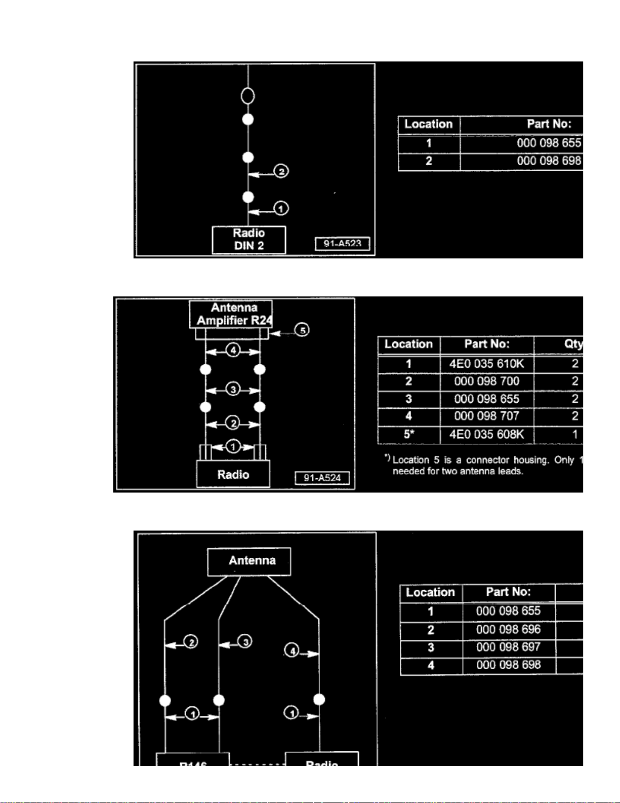
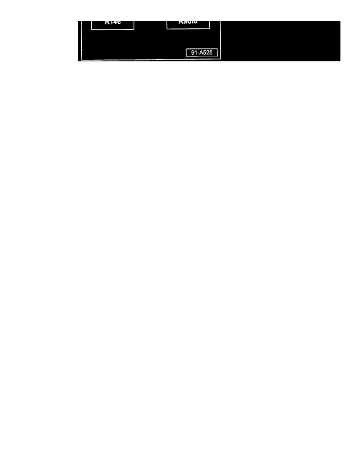
- Antenna cables - double DIN (Premium VI) radio.
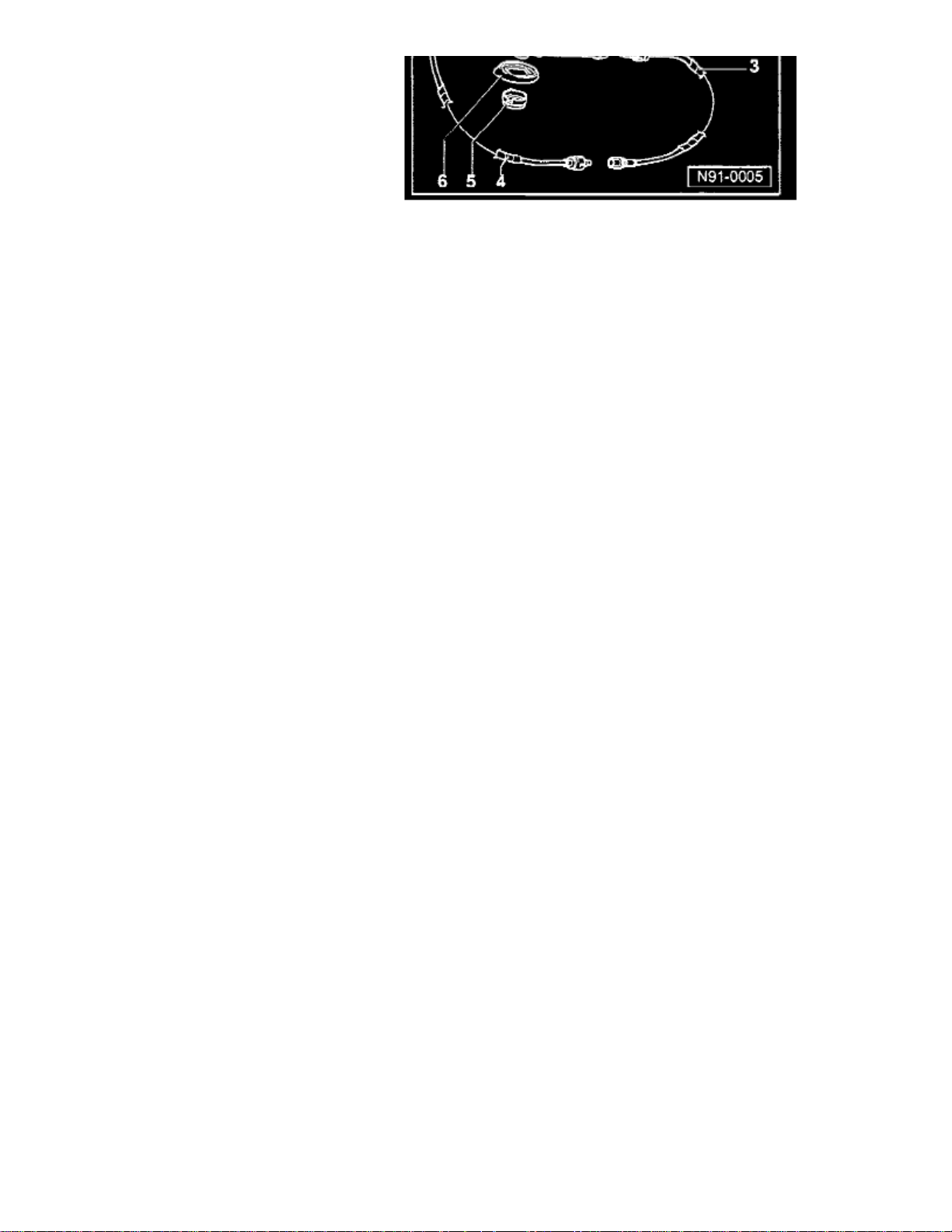
- Antenna cables - Phaeton 2004 > 2006
Page 21
> Relays and Modules > Relays and Modules - Accessories and Optional Equipment > Antenna Control Module > Component Information > Technical Service Bulletins >
Customer Interest for Antenna Control Module: > 9105-01 > May > 05 > Audio System - Poor Radio Reception > Page 23
Beetle L4-2.0L (AEG) (2000)
- Antenna cables - Satellite radio (Hard top vehicles)
Page 22

- Antenna cables - New Beetle with Satellite radio (convertible)
- Antenna cables - W8 Passat
Page 23

> Relays and Modules > Relays and Modules - Accessories and Optional Equipment > Antenna Control Module > Component Information > Technical Service Bulletins >
Customer Interest for Antenna Control Module: > 9105-01 > May > 05 > Audio System - Poor Radio Reception > Page 24
Beetle L4-2.0L (AEG) (2000)
Page 24
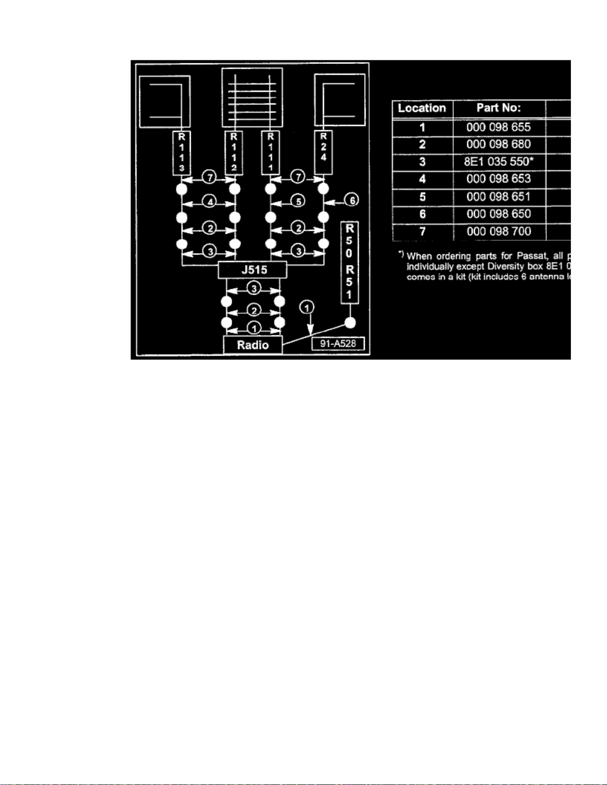
- Antenna cables - Touareg 2004 > 2006
Tip:
Part numbers listed in this bulletin are for reference only Always check with your Parts Dept. for the latest parts information.
Page 25

Page 26

> Relays and Modules > Relays and Modules - Accessories and Optional Equipment > Antenna Control Module > Component Information > Technical Service Bulletins > All Technical Service Bulletins for Antenna Control
Module: > 9105-01 > May > 05 > Audio System - Poor Radio Reception
Technical Service Bulletin # 9105-01
Audio System - Poor Radio Reception
Group: 91
Number: 05-01
Date: May 2, 2005
Subject: Radio, Reception Diagnosis
Model(s): All with Premium V and VI Radio
1998 > 2006
Condition
Poor radio reception.
Service Procedure
For concerns of poor radio reception:
- Use the following as a guide for trouble shooting.
Tip:
This Technical Bulletin is divided into four sections:
^ Section 1: Includes antenna systems by vehicle.
^ Section 2: Includes radio antenna system diagnosis procedures for AM/FM concerns using internal radio diagnostics.
^ Section 3: Includes antenna lead diagnosis.
^ Section 4: Antenna cables
Tip:
^ Perceived reception issues may be a result of environmental factors.
^ Reception may be diminished in certain areas due to power wires, buildings and/or overpasses.
^ Aftermarket window tint may interfere with reception.
^ In cases that are questionable, locate identical vehicle and verify concern (if the like vehicle is same, condition may be normal).
Section 1 - Antenna systems by vehicle
Tip:
For more detail see Repair Manual Group 91- Communication of the vehicle you are working on.
Passat (W8 only)
Page 27

> Relays and Modules > Relays and Modules - Accessories and Optional Equipment > Antenna Control Module > Component Information > Technical Service Bulletins > All
Technical Service Bulletins for Antenna Control Module: > 9105-01 > May > 05 > Audio System - Poor Radio Reception > Page 30
Beetle L4-2.0L (AEG) (2000)
Page 28
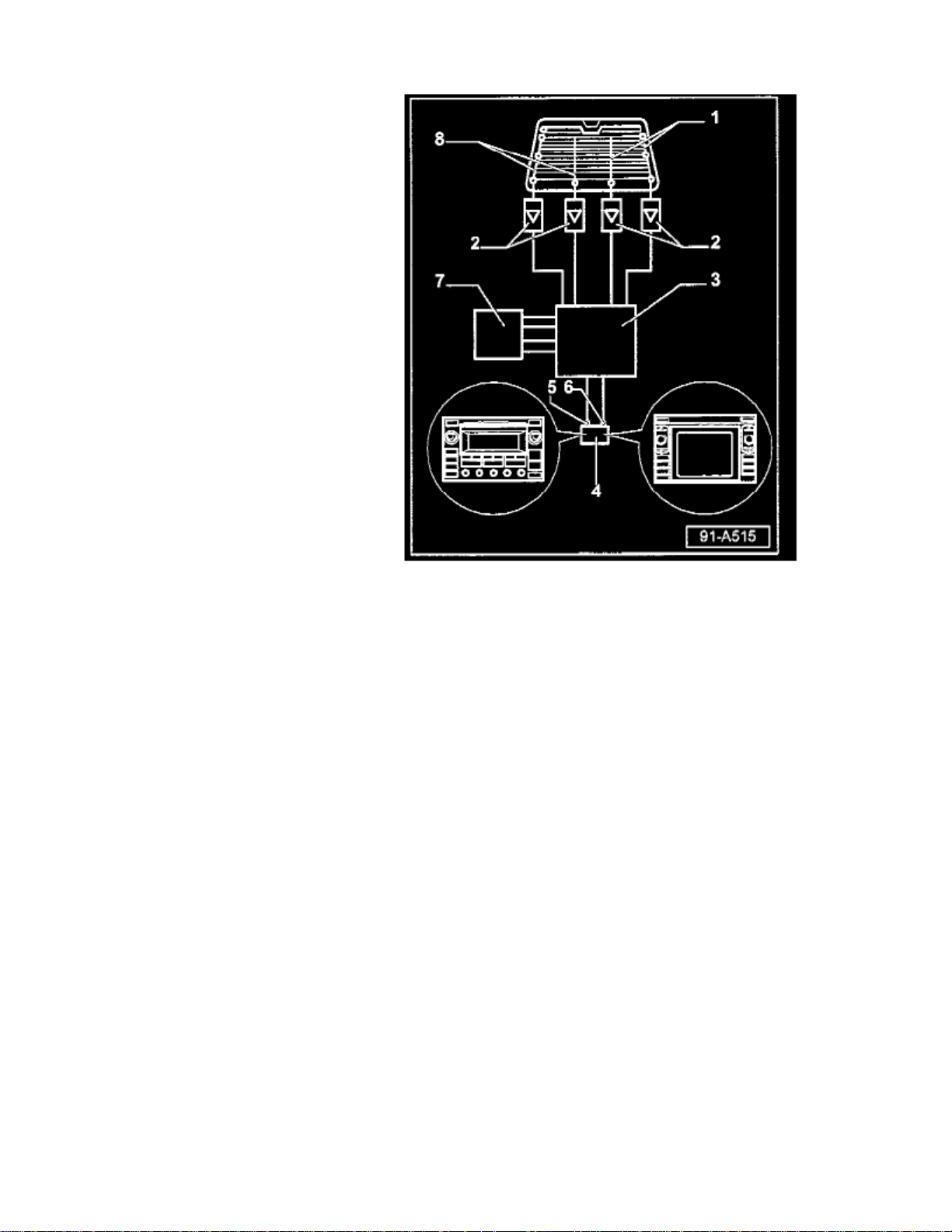
- Antenna Selection Control Module -J515- (Diversity box) -3-:
^ Location Wagon; behind left luggage compartment side trim, below rear side window.
^ Location, Sedan: under rear parcel shelf.
Antennas:
All models use four antennas -1-, -8-.
^ Location Wagon: Integrated with rear side windows.
^ Location Sedan: Integrated with rear window.
Antenna amplifiers:
All models use four antenna amplifiers -2-.
^ Location,Wagon: 2 each behind left and right luggage compartment side trim, below rear side windows.
^ Location Sedan: 2 under rear parcel shelf and 1 each behind left and right rear D-pillar trim.
Touareg
Page 29

> Relays and Modules > Relays and Modules - Accessories and Optional Equipment > Antenna Control Module > Component Information > Technical Service Bulletins > All
Technical Service Bulletins for Antenna Control Module: > 9105-01 > May > 05 > Audio System - Poor Radio Reception > Page 31
Beetle L4-2.0L (AEG) (2000)
Page 30
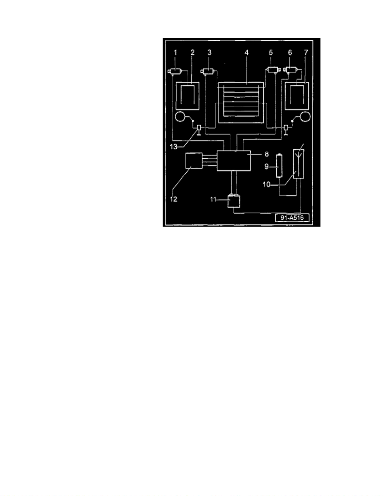
- Antenna Selection Control Module -J515- (Diversity box)
All models use an Antenna Selection Control Module -J515- item -8-.
^ Location: Behind rear section of molded headlining.
Antennas
All models use four antennas items -2-, 4- (qty. 2) & -7-.
^ Antennas (R130, R131) are integrated into rear hatch glass.
^ Antenna R11 in left rear side glass.
^ Antenna R93 in right rear side glass.
Antenna amplifiers
All models use four antenna amplifiers items -1-, -3-, -5- & -6-.
^ Item 1 - Antenna Amplifier 1 -R24- (for AM and FM reception). Above left side window.
^ Item 3 - Antenna Amplifier 2 -R111- (for FM reception). In upper section of rear lid.
^ Item 5 - Antenna Amplifier 3 -R112- (for FM reception). In upper section of rear lid.
^ Item 6 - Antenna Amplifier 4 -R113- (for FM reception). Above right side window.
Page 31

> Relays and Modules > Relays and Modules - Accessories and Optional Equipment > Antenna Control Module > Component Information > Technical Service Bulletins > All
Technical Service Bulletins for Antenna Control Module: > 9105-01 > May > 05 > Audio System - Poor Radio Reception > Page 32
Beetle L4-2.0L (AEG) (2000)
Phaeton
Page 32
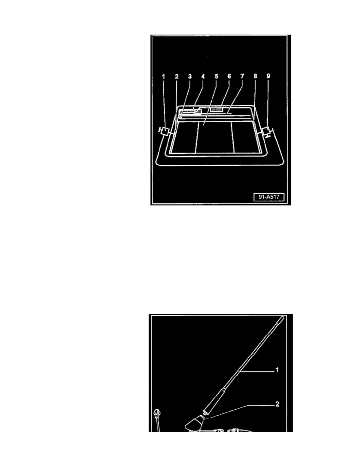
- Antenna Selection Control Module -J515- (Diversity box)
All models use an Antenna Selection Control Module -J515- item -4-.
^ Location: Above rear glass under headliner.
Antennas
All models use four antennas.
^ Antennas -2-, -7- and -8- (for FM reception). Integrated into rear glass -5^ Antenna -3- (for AM and FM reception). Integrated into rear glass -5-.
Page 33
> Relays and Modules > Relays and Modules - Accessories and Optional Equipment > Antenna Control Module > Component Information > Technical Service Bulletins > All
Technical Service Bulletins for Antenna Control Module: > 9105-01 > May > 05 > Audio System - Poor Radio Reception > Page 33
Beetle L4-2.0L (AEG) (2000)
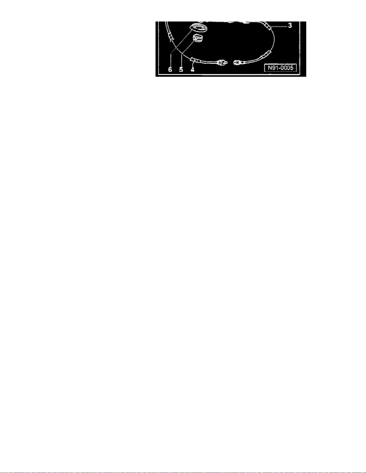
- Jetta / Golf / Passat (non W8) - Antenna system
^ All models use External amplified antenna mast -1-.
Page 34
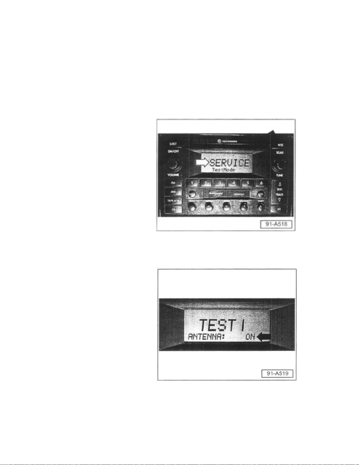
Section 2 - Radio antenna system diagnosis through radio unit
Premium VI radios are capable of signal diagnosis through operating internal diagnostics of the radio unit.
All models except Touareg and Phaeton:
- Select AM or FM.
- Press and hold the mix button (black arrow).
- Screen will appear that shows "Service Test mode" (white arrow).
- Press mix button briefly.
^ Test one indicates current antenna status, i.e. ON or OFF (arrow).
- Press mix button briefly again.
Page 35

> Relays and Modules > Relays and Modules - Accessories and Optional Equipment > Antenna Control Module > Component Information > Technical Service Bulletins > All
Technical Service Bulletins for Antenna Control Module: > 9105-01 > May > 05 > Audio System - Poor Radio Reception > Page 34
Beetle L4-2.0L (AEG) (2000)
Page 36
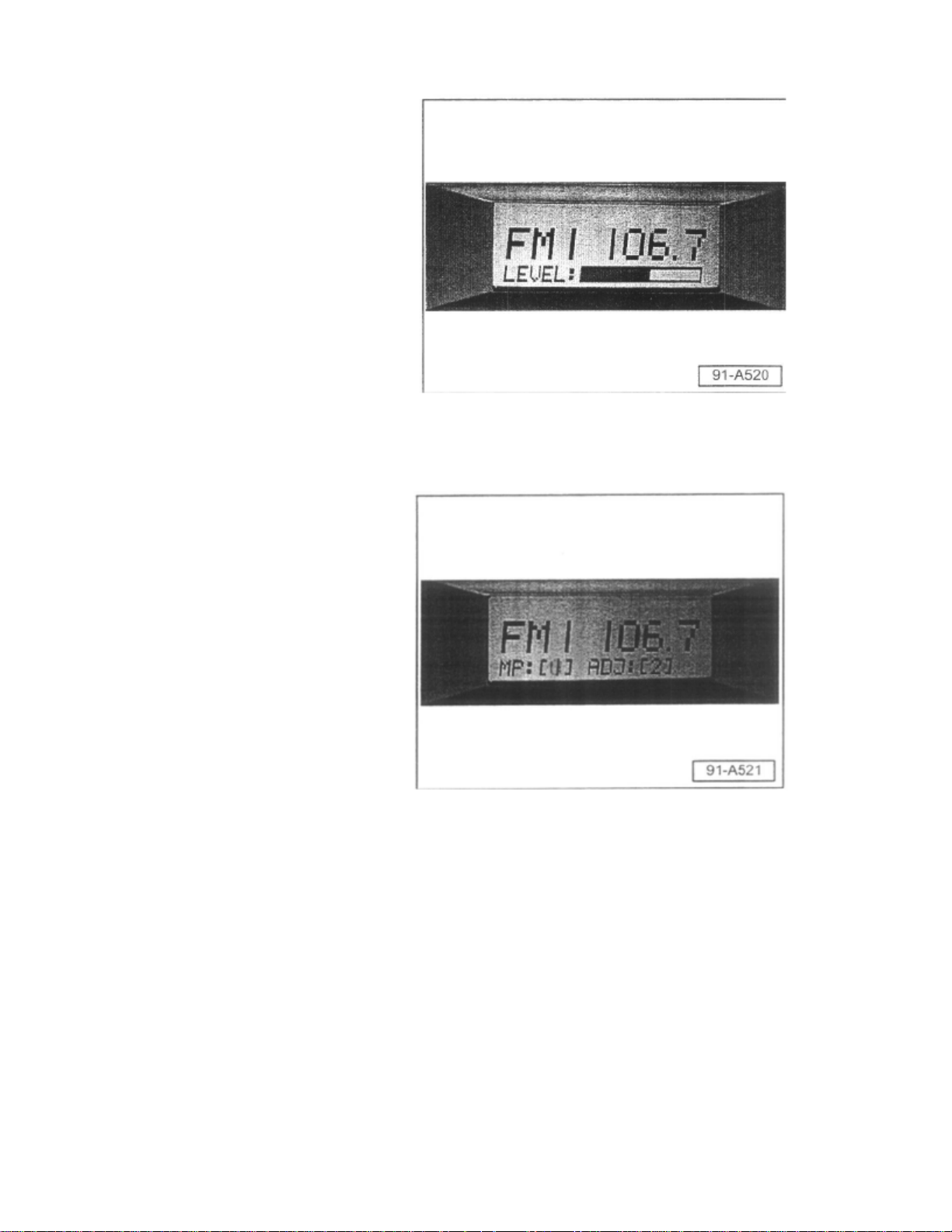
- Screen displays strength of signal (LEVEL) in bar graph form (can be used for AM and FM).
- Press mix button briefly again.
^ Screen indicates number of stations broadcasting close to frequency band of selected station.
^ As the number increases for [mp] and (adj], static and signal crossing will increase.
To exit service mode:
- Depress and hold the mix button or switch radio OFF then back ON
Navigation units
^ No internal diagnosis functions. Continue to antenna lead diagnosis.
Section 3 - Antenna Lead Diagnosis
After initial radio diagnosis using internal service functions, use the following procedures:
- Locate antenna lead/s from radio at system end-point, i.e. diversity box or antenna mast base.
Page 37

> Relays and Modules > Relays and Modules - Accessories and Optional Equipment > Antenna Control Module > Component Information > Technical Service Bulletins > All
Technical Service Bulletins for Antenna Control Module: > 9105-01 > May > 05 > Audio System - Poor Radio Reception > Page 35
Beetle L4-2.0L (AEG) (2000)
- Check for proper connection. (follow steps for your type of system).
- For all systems, locate cable end-point at either diversity box or antenna mast base.
- Disconnect cable from either diversity box or antenna mast base.
- Carefully ground center wire in cable to chassis.
If reception returns:
^ Cable and radio are ok.
Page 38

If reception does not return:
^ Problem is located further forward in the system.
For problems forward of the antenna system:
- Continue with Section 3a.
For problems at antenna system:
Skip to Section 3b.
For problems at antenna systems:
Tip:
All checks should be done outdoors away from buildings.
Section 3a - Problems forward of antenna system
- First verify connection at Radio (check for bent or crushed connections and proper fit).
If all connections appear ok:
- Ground antenna lead at radio or attach external antenna mast to radio unit (check for reception).
If reception returns:
^ Problem is located between radio and antenna.
- Check connections near center console:
If connections are OK:
- Check resistance of cable from end to end.
^ If More than .4 ohms:
- Replace cable.
If reception does not return;
- Replace radio unit.
Section 3b - Problems at antenna system, Diversity Antenna (Touareg, Passat W8)
If concern is only AM poor / no reception;
Locate AM antenna amplifier.
^ Touareg: located above left side window.
Page 39

> Relays and Modules > Relays and Modules - Accessories and Optional Equipment > Antenna Control Module > Component Information > Technical Service Bulletins > All
Technical Service Bulletins for Antenna Control Module: > 9105-01 > May > 05 > Audio System - Poor Radio Reception > Page 36
Beetle L4-2.0L (AEG) (2000)
^ Passat W8: Sedan above rear window.
^ Passat Wagon: located on left rear window.
- Check for proper connections at amplifier both from diversity box and to glass.
If connection issue is at glass or on glass:
- Glass must be replaced.
If connection problem to amplifier:
- Repair connection (replace cable or amplifier).
Page 40
If no apparent connection problems:
- Replace amplifier.
If concern is poor FM reception:
- Disconnect all amplifiers, tune radio to high-powered station for your area.
- Connect amplifiers one at a time.
If reception is indicated:
- Disconnect that amplifier and move on to next amplifier.
If at any point in reconnecting amplifiers there is a loss in reception and there are no connection issues:
- Replace that amplifier and check again.
If there is no reception change when disconnecting and reconnecting all amplifiers:
- Replace diversity/antenna selection box.
Jetta / Golf / Passat (non W8) - Antenna system (Amplified Antenna Mast)
- Check connections at antenna base.
- Check for corrosion at mounting.
If corrosion is found:
- Clean mount and apply anti-seize gel to mounting.
If concern is no AM and/or little or poor AM/FM reception,
- Replace antenna base.
Section 4- Antenna cables
If antenna cables are required:
Page 41

> Relays and Modules > Relays and Modules - Accessories and Optional Equipment > Antenna Control Module > Component Information > Technical Service Bulletins > All
Technical Service Bulletins for Antenna Control Module: > 9105-01 > May > 05 > Audio System - Poor Radio Reception > Page 37
Beetle L4-2.0L (AEG) (2000)
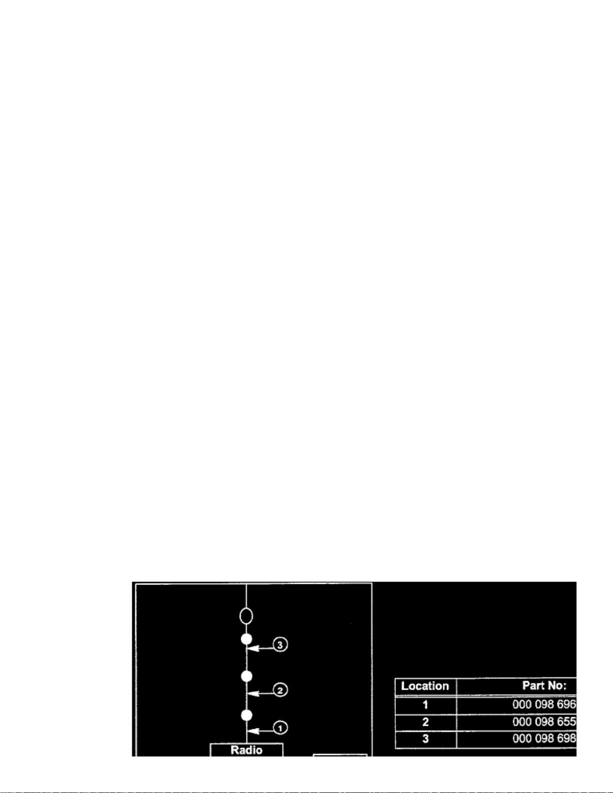
- Antenna cables - single DIN (Premium V) radio.
Page 42
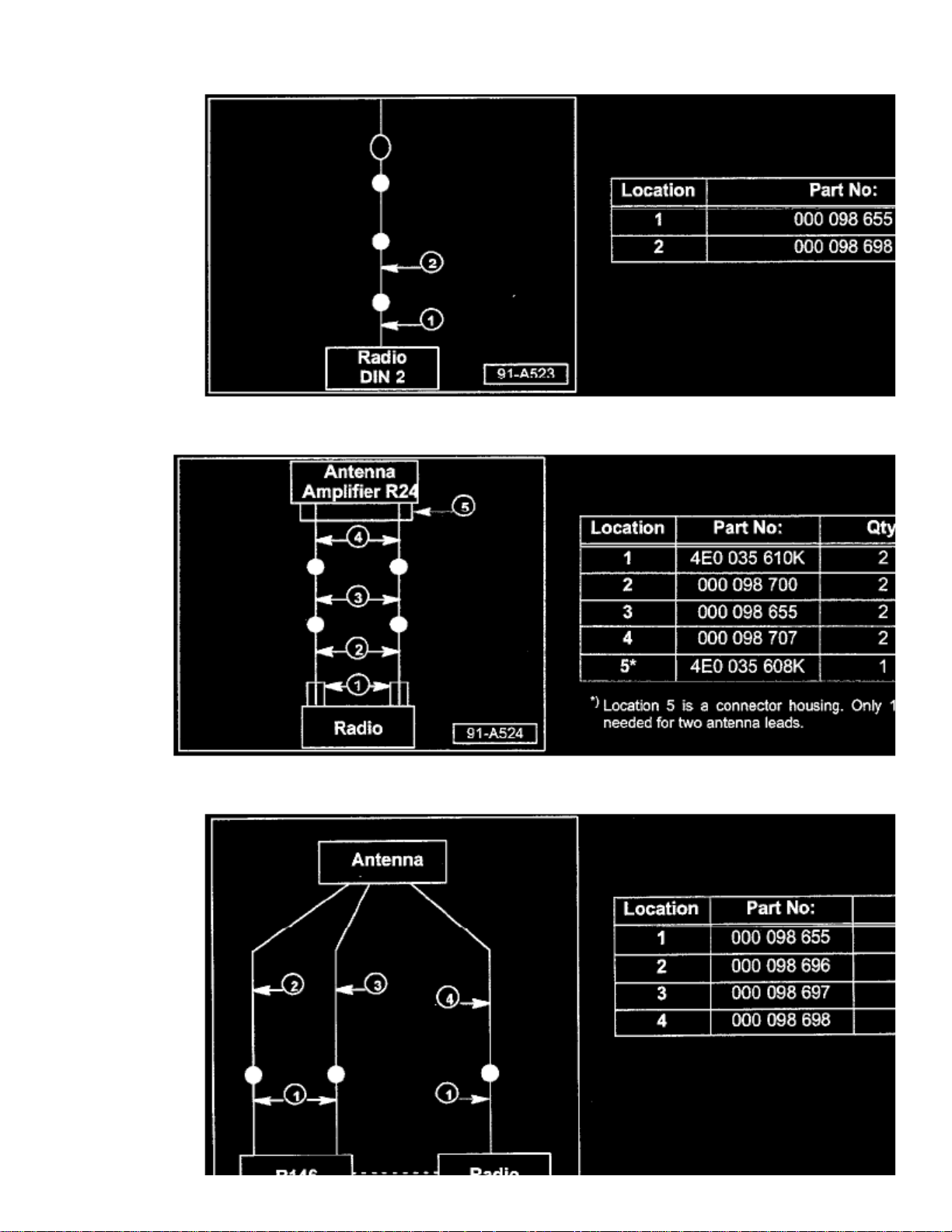
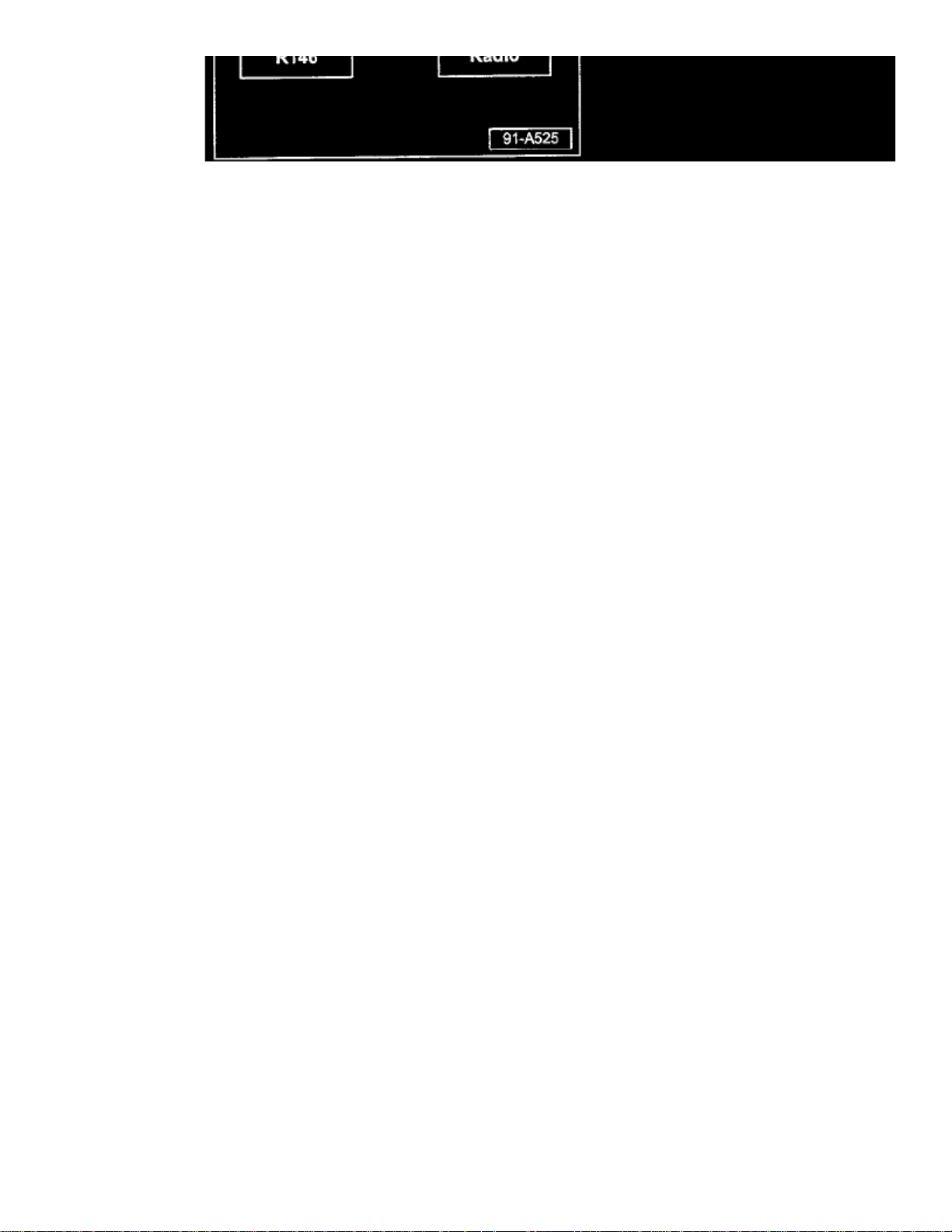
- Antenna cables - double DIN (Premium VI) radio.
- Antenna cables - Phaeton 2004 > 2006
Page 43
> Relays and Modules > Relays and Modules - Accessories and Optional Equipment > Antenna Control Module > Component Information > Technical Service Bulletins > All
Technical Service Bulletins for Antenna Control Module: > 9105-01 > May > 05 > Audio System - Poor Radio Reception > Page 38
Beetle L4-2.0L (AEG) (2000)
- Antenna cables - Satellite radio (Hard top vehicles)
Page 44
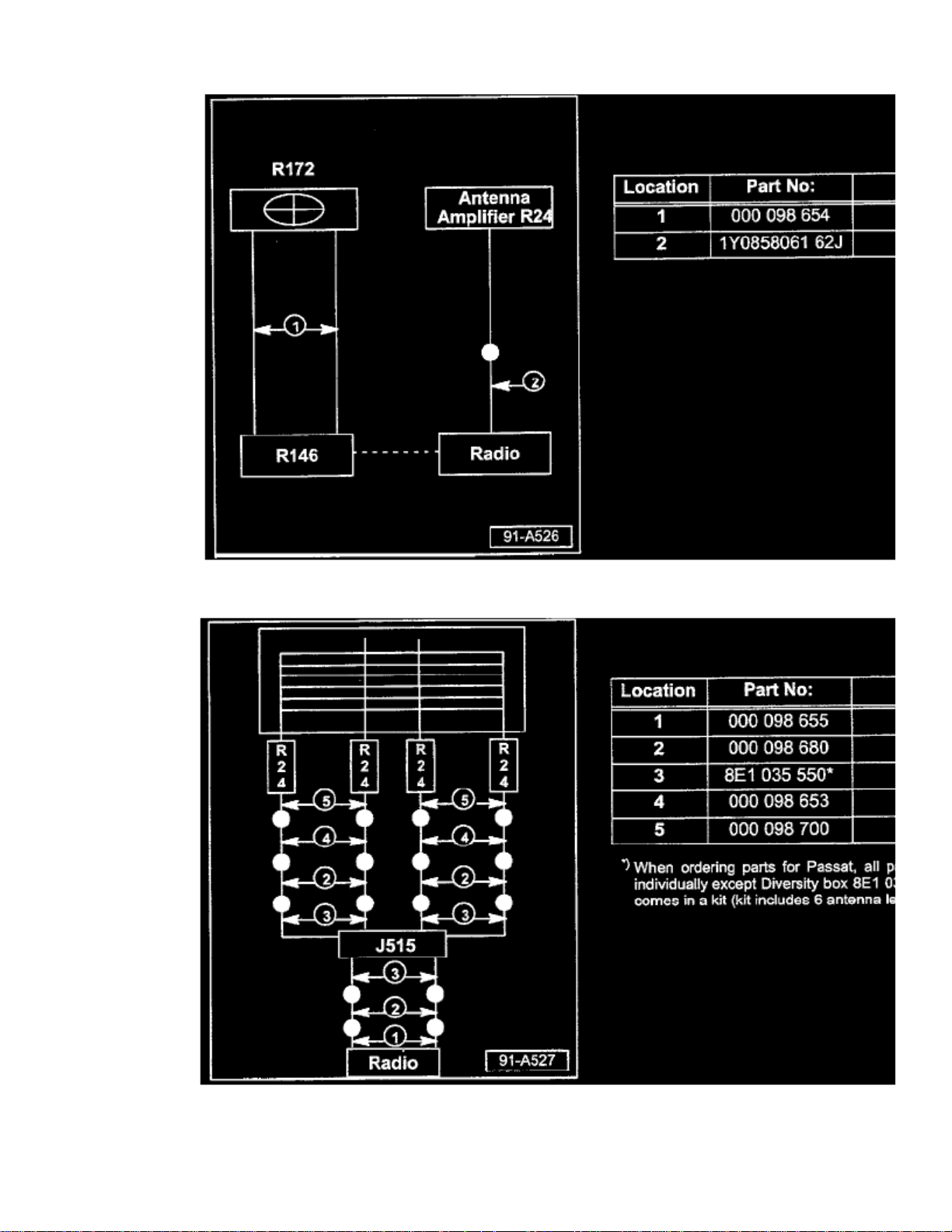
- Antenna cables - New Beetle with Satellite radio (convertible)
- Antenna cables - W8 Passat
Page 45

> Relays and Modules > Relays and Modules - Accessories and Optional Equipment > Antenna Control Module > Component Information > Technical Service Bulletins > All
Technical Service Bulletins for Antenna Control Module: > 9105-01 > May > 05 > Audio System - Poor Radio Reception > Page 39
Beetle L4-2.0L (AEG) (2000)
Page 46
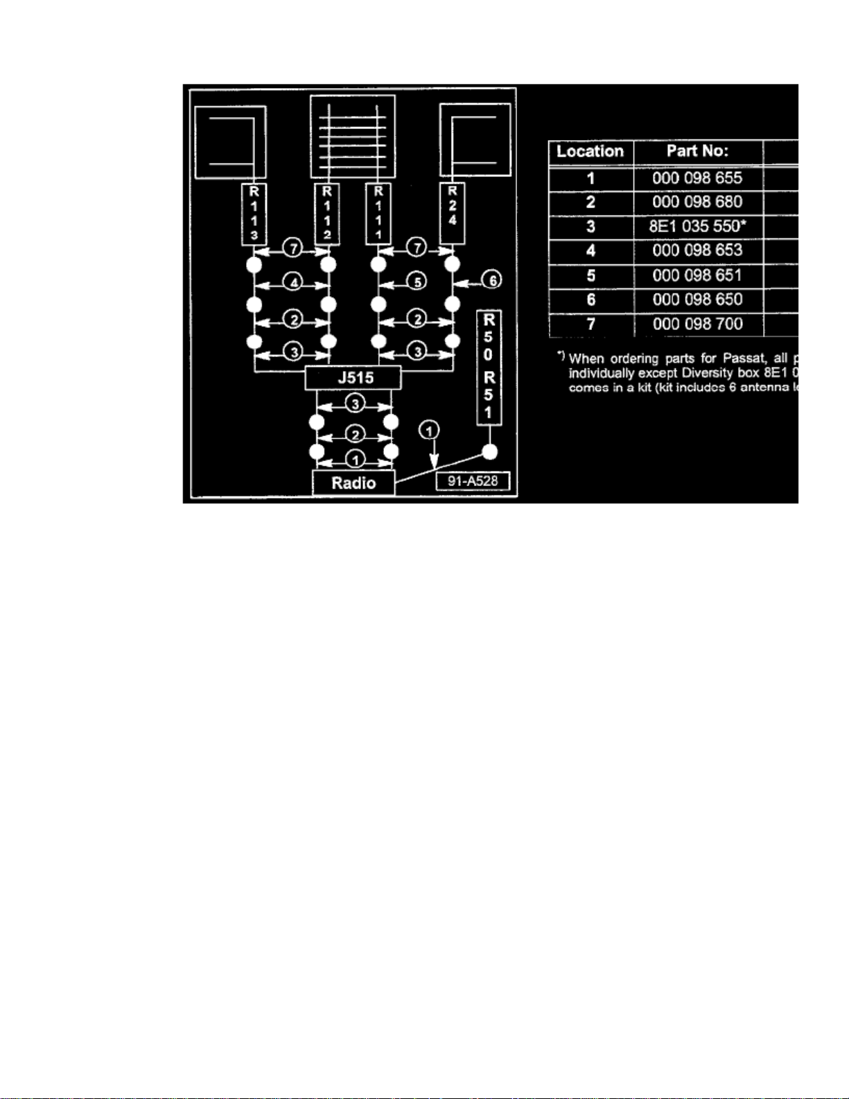
- Antenna cables - Touareg 2004 > 2006
Tip:
Part numbers listed in this bulletin are for reference only Always check with your Parts Dept. for the latest parts information.
Page 47

Page 48
> Relays and Modules > Relays and Modules - Accessories and Optional Equipment > Antitheft Lighting Relay > Component Information > Locations
Antitheft Lighting Relay: Locations
RELAY LOCATIONS
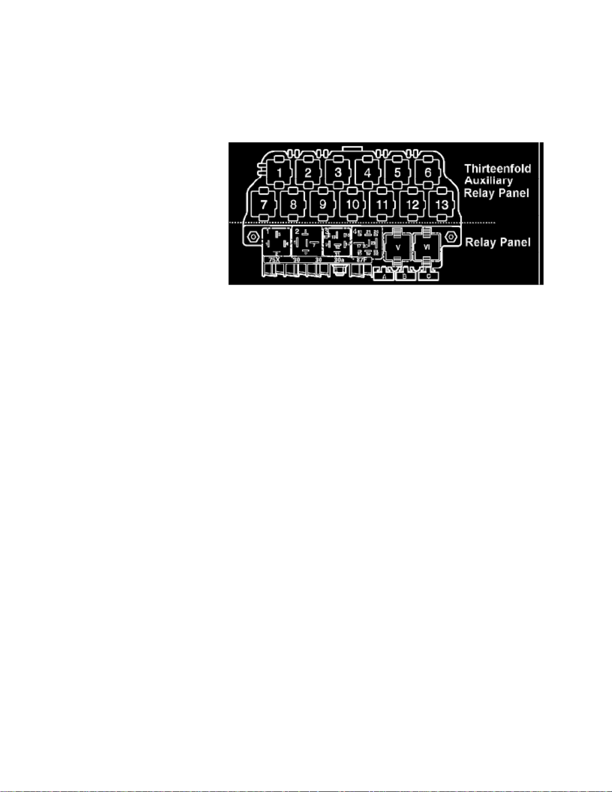
Relay Panel & Thirteenfold Auxiliary Relay Panel
Relay location on the thirteen position auxiliary relay panel, above relay panel:
1 - Alarm System Light Flasher Relay (404)
2 - Alarm System Light Flasher Relay (200)
3 - Back-up Light Relay (53)
3 - Lock Relay for Starter (Theft Warning System) (185)
4 - Lock Relay for Starter (Clutch pedal Switch) (53)
7 - Daytime Running Lights Change-over Relay (173)
8 - Daytime Running Lights Change-over Relay (173)
8 - Heated Exterior Mirror Relay (53)
9 - Alarm Horn Relay (53)
10 - Glow Plug Relay (180)
10 -
Third Speed Coolant Fan Control (FC) Relay (100)*
11 - Park/Neutral Position (PNP) Relay (126) (175)
12 - Power Supply (Terminal 30, B+) Relay (109)
Only applies to 1.8L turbo engines*
Relay panel:
1 - Dual Horn Relay (53)
2 - Load Reduction Relay (18) (100) (213)
4 - Fuel Pump (FP) Relay (409)
V - Wiper/Washer Intermittent Relay (192) (377) (389)
VI - Wiper/Washer Intermittent Relay (192) (377) (389)
Number in parentheses ( ) indicates production control number stamped on relay housing.NOTE
Page 49

Page 50
> Relays and Modules > Relays and Modules - Body and Frame > Heated Mirror Relay > Component Information > Locations
Heated Mirror Relay: Locations
RELAY LOCATIONS
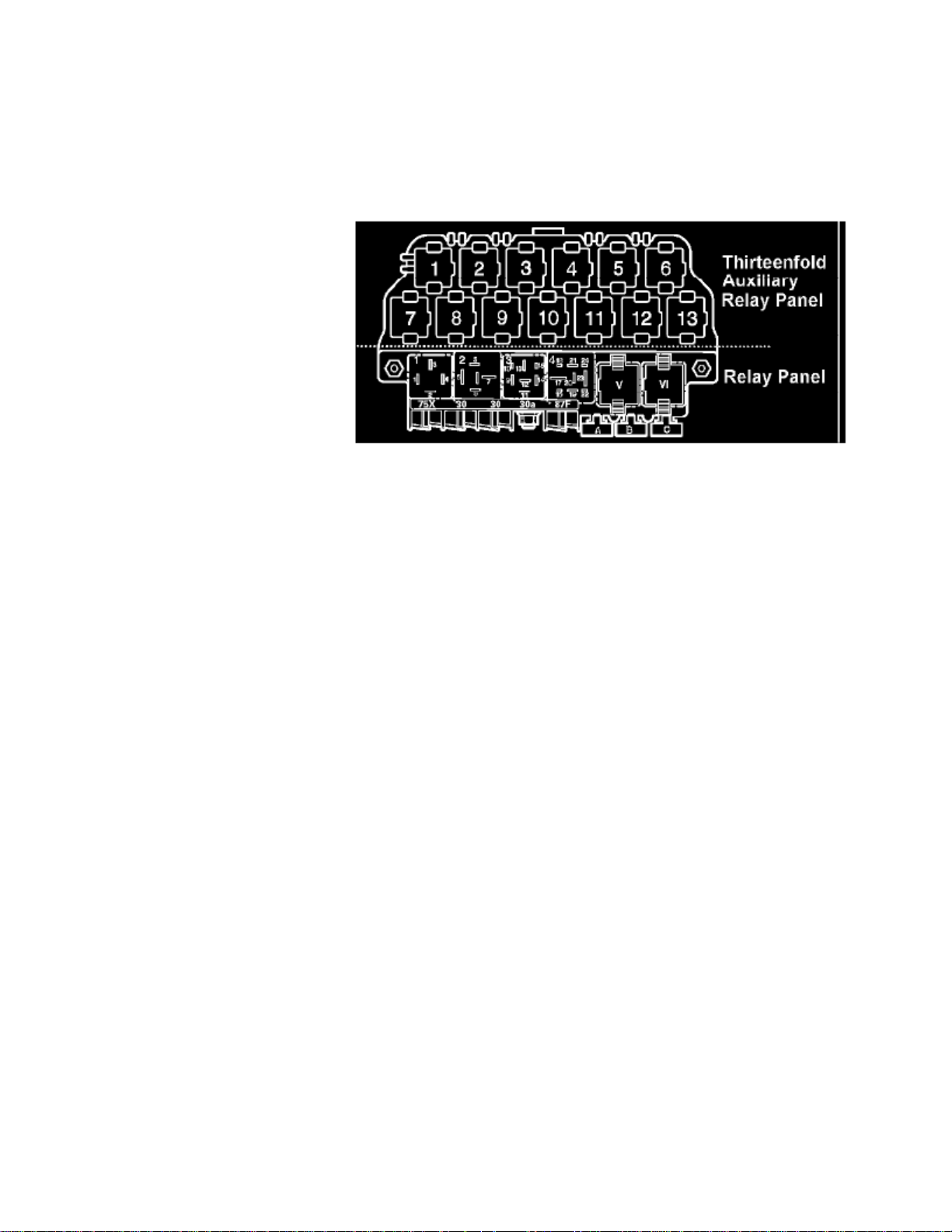
Relay Panel & Thirteenfold Auxiliary Relay Panel
Relay location on the thirteen position auxiliary relay panel, above relay panel:
1 - Alarm System Light Flasher Relay (404)
2 - Alarm System Light Flasher Relay (200)
3 - Back-up Light Relay (53)
3 - Lock Relay for Starter (Theft Warning System) (185)
4 - Lock Relay for Starter (Clutch pedal Switch) (53)
7 - Daytime Running Lights Change-over Relay (173)
8 - Daytime Running Lights Change-over Relay (173)
8 - Heated Exterior Mirror Relay (53)
9 - Alarm Horn Relay (53)
10 - Glow Plug Relay (180)
10 -
Third Speed Coolant Fan Control (FC) Relay (100)*
11 - Park/Neutral Position (PNP) Relay (126) (175)
12 - Power Supply (Terminal 30, B+) Relay (109)
Only applies to 1.8L turbo engines*
Relay panel:
1 - Dual Horn Relay (53)
2 - Load Reduction Relay (18) (100) (213)
4 - Fuel Pump (FP) Relay (409)
V - Wiper/Washer Intermittent Relay (192) (377) (389)
VI - Wiper/Washer Intermittent Relay (192) (377) (389)
Number in parentheses ( ) indicates production control number stamped on relay housing.NOTE
Page 51

Page 52
> Relays and Modules > Relays and Modules - Body and Frame > Power Door Lock Control Module > Component Information > Locations > Driver Side
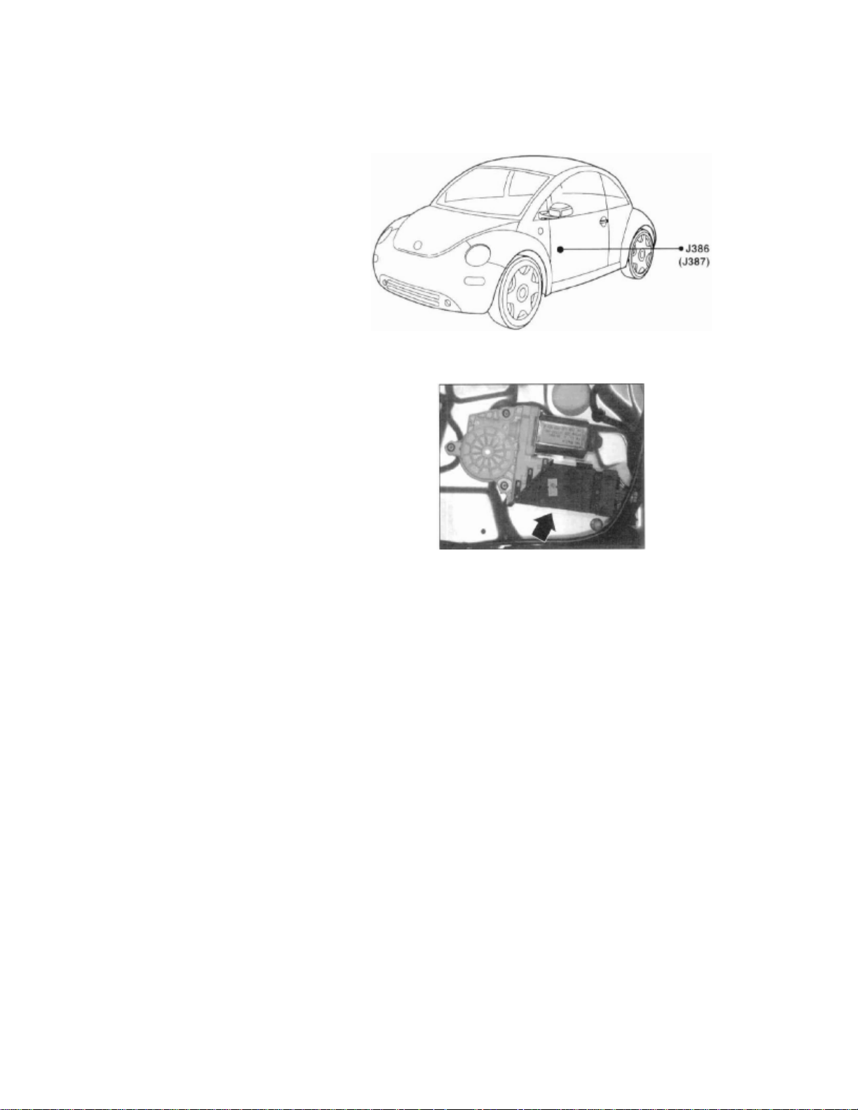
Power Door Lock Control Module: LocationsDriver Side
J386 (J387)
J386 (J387)
Component View
J386 Door Control Module, Driver Side
^ In driver's door, on component carrier
^ Integral with window motor -V147-
Page 53

Page 54
> Relays and Modules > Relays and Modules - Body and Frame > Power Door Lock Control Module > Component Information > Locations > Driver Side > Page 51
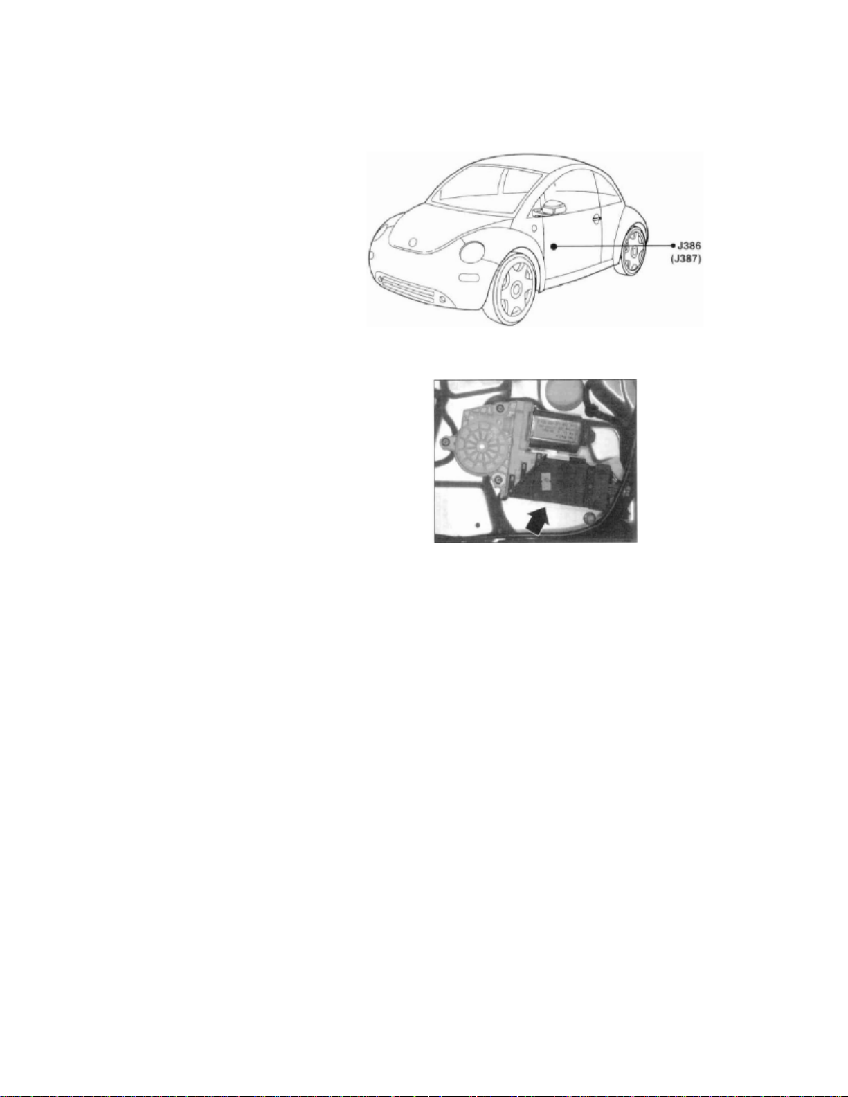
Power Door Lock Control Module: LocationsPassenger Side
J386 (J387)
J386 (J387)
Component View
J387 Door Control Module, Passenger Side
^ In passenger door, on component carrier
^ Integral with window motor -V148^ Left-side module -J386- shown
Page 55

Page 56

> Relays and Modules > Relays and Modules - Body and Frame > Power Door Lock Control Module > Component Information > Diagrams > Diagram Information and Instructions
Power Door Lock Control Module: Diagram Information and Instructions
How to Find Wiring Diagrams
: Wiring Diagrams are classified by OE as belonging to one of three categories.NOTE
:These Three OE Categories Are:
1 - Standard Equipment2 - Engine Specific3 - System Specific and Optional Equipment (Common Systems)
Standard Equipment
This category includes equipment such as Instrument Cluster and Gauges, Headlights/Tail Lights/Turn Signals, Rear Window Defroster, Wipersand Washers, etc...
Standard equipment is found on all vehicles regardless of which engine or optional equipment is installed.
The Standard Equipment diagrams can be found at Power and Ground Distribution diagrams, or via a component name on the at the vehicle level diagrams.Master DiagramIndex
Engine Specific
This category includes components and systems circuits such as Starting and Charging Systems, Engine Controls, Ignition System, Fuel InjectionSystem, etc., which are unique to a specific engine.
Master Diagram Index
The Engine Specific diagrams can be found at Powertrain Management diagrams, or via a component name on the at thevehicle level diagrams.
System Specific and Optional Equipment
This category includes equipment such as Air Bag Systems, Anti-lock Brake System, Heated Seats, HVAC System, Comfort System, etc.. andprovides circuit details for those systems and components.
Master Diagram Index
See: Diagrams/Electrical Diagrams/Master Diagram Index
How to Read Track Diagrams
Page 57

> Relays and Modules > Relays and Modules - Body and Frame > Power Door Lock Control Module > Component Information > Diagrams > Diagram Information and
Instructions > Page 54
Beetle L4-2.0L (AEG) (2000)
Page 58
Page 59

> Relays and Modules > Relays and Modules - Body and Frame > Power Door Lock Control Module > Component Information > Diagrams > Diagram Information and
Instructions > Page 55
Beetle L4-2.0L (AEG) (2000)
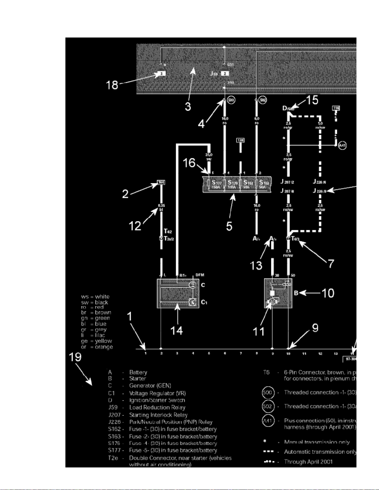
Wiring Diagram Layout
1 - Track Numbers
Imaginary grid lines extending from the numbers on the bottom of the diagram toward the top of the diagram. These imaginary grid lines are used foridentifying wire/circuit locations on diagrams.
2 - Reference of wire/circuit continuation to another diagram
Page 60

this
other
Number in frame indicates track where the wire/circuit is continued. For example, the reference in diagram is to track 164, which is on anotherdiagram. In the diagram showing track 164, the number in the frame for the same wire/circuit will change to the number 2, as that is the tracknumber for where the wire/circuit came from on diagram.this
Indicated by grey area.3 - Relay Panel -
4 - Diagram of threaded pin on relay panel
White circle shows a detachable connection.
5 - Fuse designation
Use legend at bottom of page to identify the fuse code.
6 - Arrow
Indicates wiring circuit is continued on the previous and/or next diagram.
7 - Wire connection designation in wiring harness
Location of wire connections are indicated in the legend.
8 - Terminal designation
Designation which appears on actual component and/or terminal number of a multi-point connector. For example: J226/8 = PNP Relay/terminal #8.
9 - Ground connection
10 - Component designation
Use legend at bottom of page to identify the component.
11 - Component symbols
12 - Wire cross-section size (in mm sq.) and wire colors
13 - Component symbol with open drawing side
Indicated component is continued on another wiring diagram.
15 - Reference of continuation of wire to component
For example: D/50b = Ignition/Starter Switch/terminal 50b.
16 - Relay panel connectors
Shows wiring of multi-point or single connectors on relay panel.
17 - Reference of internal connection continuation
Letters indicate where connection continues on the previous and/or next diagram.
18 - Relay location number
Indicates the physical location of the relay (by position number) on the relay panel. (For an actual relay panel image/view, see the component locationfor the relay in question.)
19 - Legend
Page 61

> Relays and Modules > Relays and Modules - Body and Frame > Power Door Lock Control Module > Component Information > Diagrams > Diagram Information and
Instructions > Page 56
Beetle L4-2.0L (AEG) (2000)
14 - Internal connections (thin lines)
These connections are not wires. Internal connections are current carrying and are listed to allow tracing of current flow inside components and wiringharness.
The legend contains the explanations for all of the designation codes used within the diagram. In all wiring diagrams the same component designation(code) is used for a particular component. For example, always "A" for the battery.
Following are the most common numbered/lettered circuits:20 - Power/Ground Distribution Circuit Identification
Terminal (circuit) 1
Ignition distributor low voltage (typically used as an Engine Speed (RPM) signal for the tachometer)
Terminal (circuit) 15
Switch Battery Positive Voltage (B+) from ignition/starter switch
Terminal (circuit) 30
Battery Positive voltage (B+), hot at all times
Page 62

Terminal (circuit) 31
Ground (GND)
Terminal (circuit) 50
Starter control; switched B+ from ignition/starter switch
Terminal (circuit) 56
Switched headlight B+ from light switch
Terminal (circuit) 58
Switched parking light, taillight. illumination B+ from light switch
Terminal (circuit) S (SU)
Key in ignition circuit; switched B+ from ignition/starter switch
Terminal (circuit) X
Load reduction circuit; switched B+ from load reduction relay
How to Use Track Diagrams
Page 63

> Relays and Modules > Relays and Modules - Body and Frame > Power Door Lock Control Module > Component Information > Diagrams > Diagram Information and
Instructions > Page 57
Beetle L4-2.0L (AEG) (2000)
Page 64
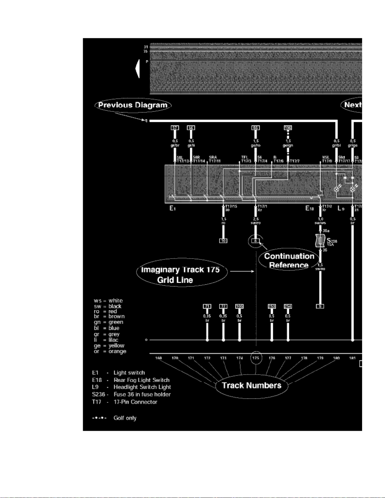
WHAT ARE TRACKS?
Page 65

> Relays and Modules > Relays and Modules - Body and Frame > Power Door Lock Control Module > Component Information > Diagrams > Diagram Information and
Instructions > Page 58
Beetle L4-2.0L (AEG) (2000)
Tracks are navigational aids, like the grid lines on a map, but they are invisible on the diagrams. They are only identified by numbers at the bottom of thediagram.
The diagram wires/circuits are laid out over these imaginary vertical lines, and each diagram is identified by the range of tracks it is laid over, not by thediagram's contents (i.e. Track 1-14, Track 15-28, and so on).
HOW DO THE WIRES/CIRCUITS WORK WITH THE TRACKS?
Wires/Circuits that do not originate/terminate on the same diagram will have a notation of where they are coming from/going to at either end.
Wires/Circuits entering/leaving the diagram in a horizontal direction will pick up again on the previous/next diagram in the series.
However, wires/circuits traveling the diagram in a vertical direction are following the tracks, and when they enter/leave a diagram they could be skipping
Page 66
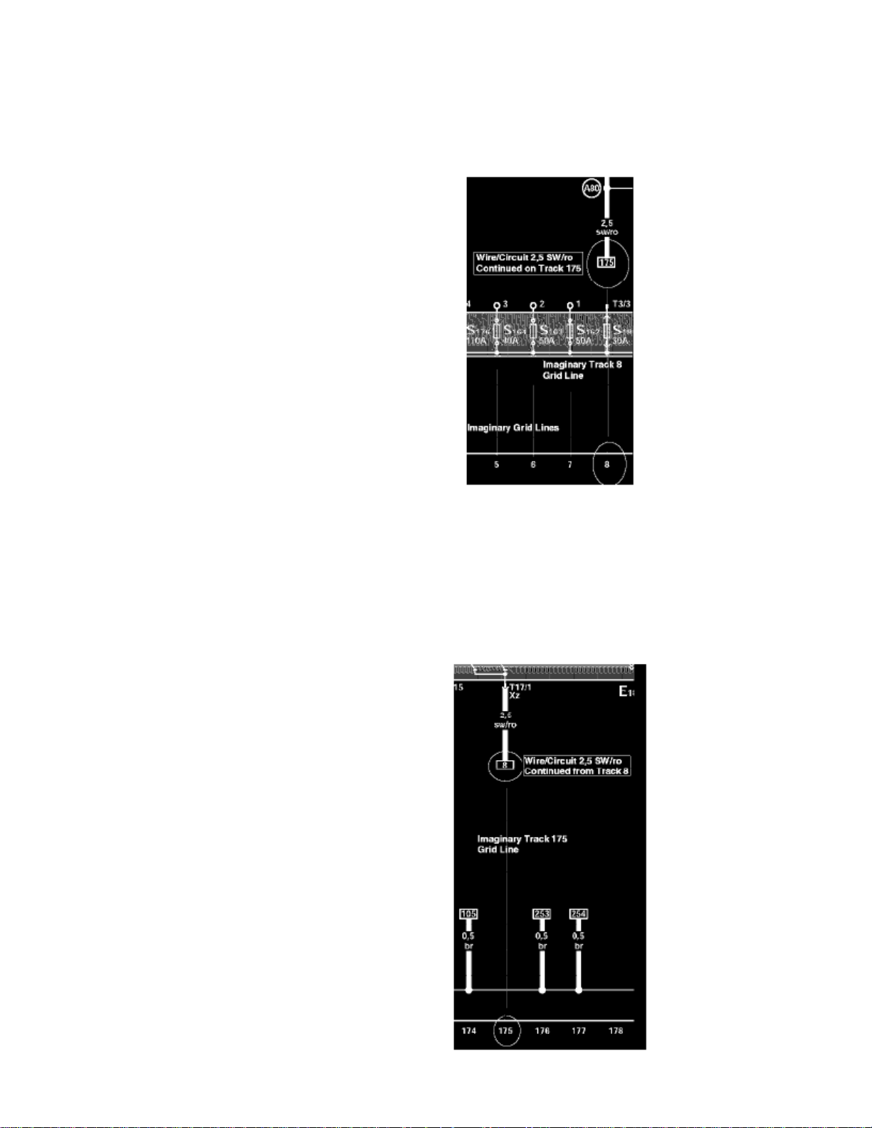
numerous diagrams in the series before picking up again on the destination diagram. When these wires/circuits enter or leave a diagram, the tracknumber of the diagram they came from/go to will be shown within a continuation reference frame/box.
HOW DO I NAVIGATE THE DIAGRAMS VIA THE TRACK NUMBERS?
Track 1-14
Assume you are tracing the wire/circuit identified by its size and color as on the diagram named Track 1-14. 2,5 sw/ro
This wire/circuit is running on track 8 of the diagram and terminates at the box labeled 175. To continue tracing this wire/circuit, you must now go toTrack 175, which is located within the diagram named Track 169-182.
But before going to the diagram named Track 169-182, again make note of the current track that you are leaving, which is Track 8.
Page 67

> Relays and Modules > Relays and Modules - Body and Frame > Power Door Lock Control Module > Component Information > Diagrams > Diagram Information and
Instructions > Page 59
Beetle L4-2.0L (AEG) (2000)
Track 169-182
After arriving at the diagram named Track 169-182, locate track 175 at the bottom of the diagram.
Follow the imaginary track 175 grid line toward the top of the diagram looking for a box labeled 8 (the track you are coming from).
2,5 sw/ro
When you locate the box labeled 8, you have picked up the continuation of wire/circuit and can continue to trace it until it terminates at eithera component or at yet another continuation reference box.
It is equally important that you always know the track that you are coming from as well as the one you are going to.NOTE:
Page 68
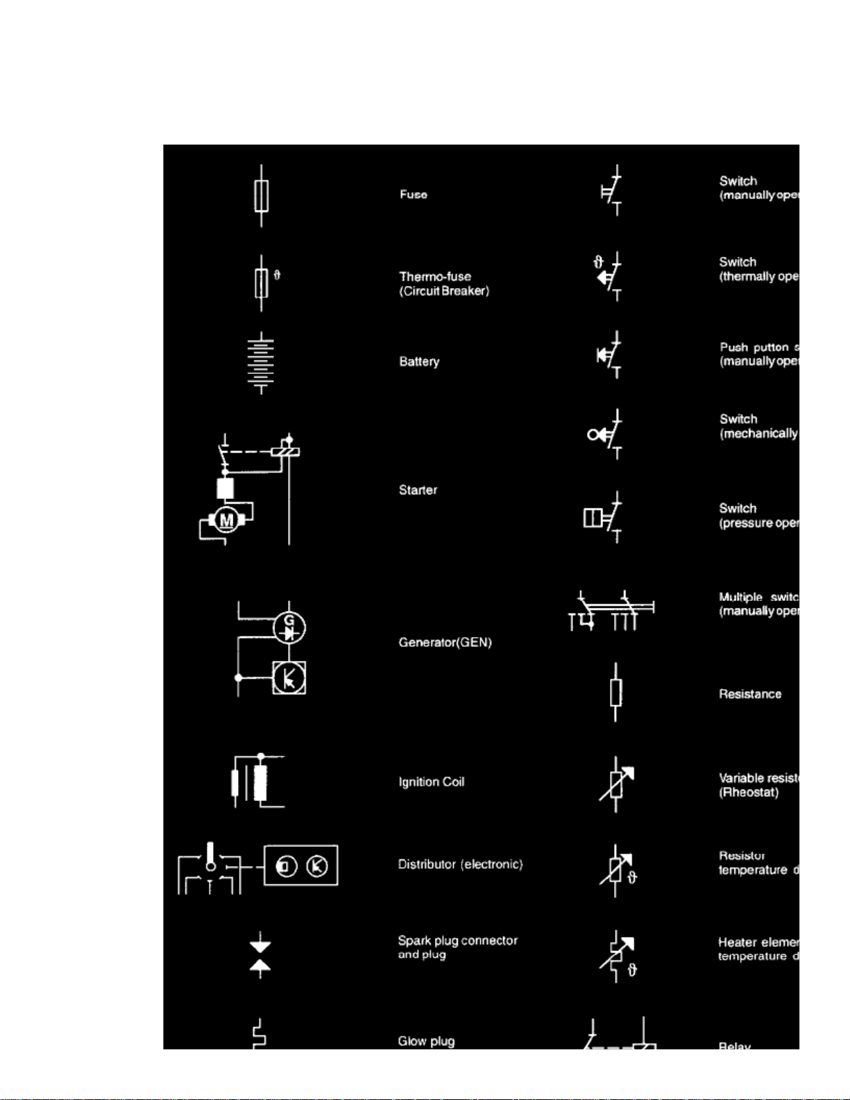
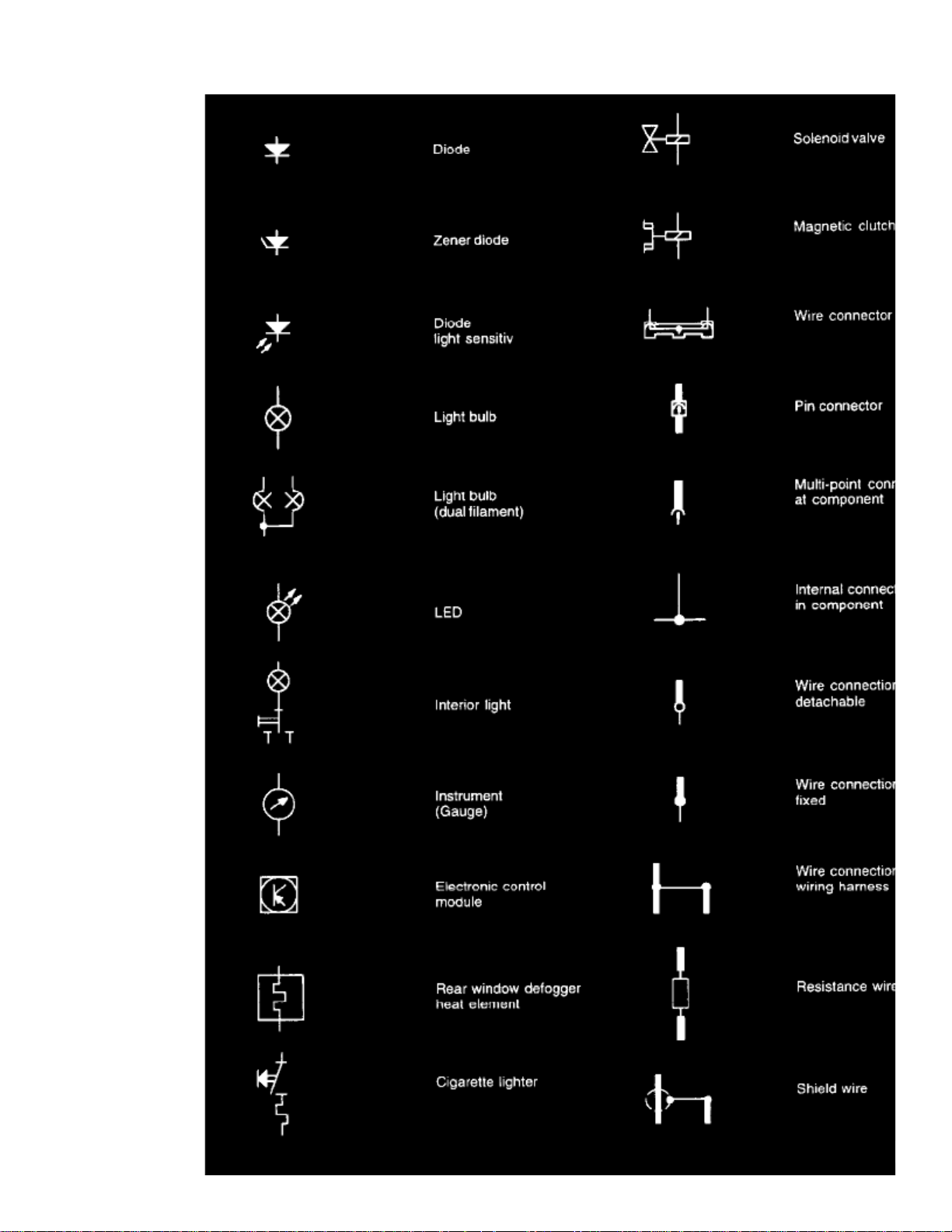
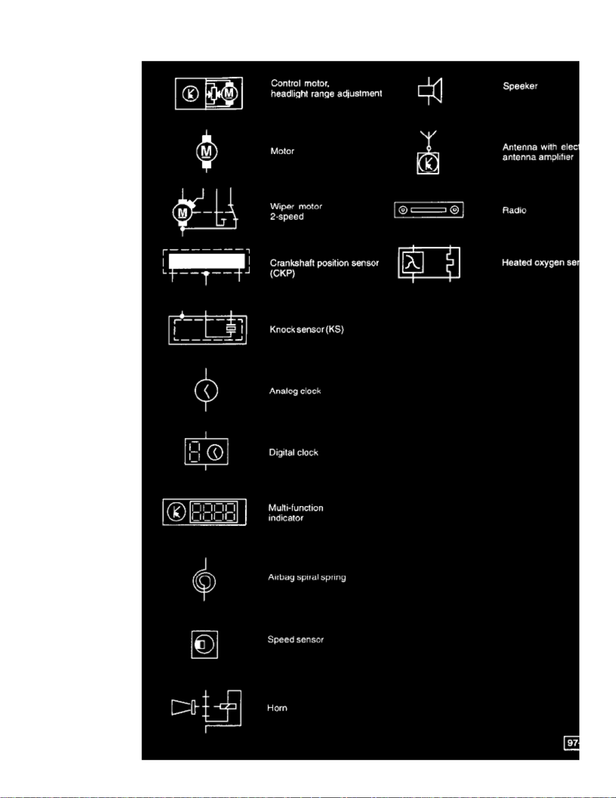
Symbols Used In Wiring Diagrams
Page 69

> Relays and Modules > Relays and Modules - Body and Frame > Power Door Lock Control Module > Component Information > Diagrams > Diagram Information and
Instructions > Page 60
Beetle L4-2.0L (AEG) (2000)
Part 1
Page 70
Page 71

> Relays and Modules > Relays and Modules - Body and Frame > Power Door Lock Control Module > Component Information > Diagrams > Diagram Information and
Instructions > Page 61
Beetle L4-2.0L (AEG) (2000)
Part 2
Page 72
Page 73

> Relays and Modules > Relays and Modules - Body and Frame > Power Door Lock Control Module > Component Information > Diagrams > Diagram Information and
Instructions > Page 62
Beetle L4-2.0L (AEG) (2000)
Part 3
Circuit and Terminal Designations
Several wiring circuits in the vehicle's electrical system are identified with a number or letter designation. These circuits are identified the same in allwiring diagrams and are most commonly shown near the top of each page in the fuse/relay panel portion of the wiring diagram. The circuit designationsmay also be used to identify switch connector terminals (switch circuits). Following are the most common numbered/lettered circuits:
Terminal (circuit) 1
Ignition distributor low voltage (typically used as an Engine Speed (RPM) signal for the tachometer)
Page 74

Terminal (circuit) 15
Switch Battery Positive Voltage (B+) from ignition/starter switch
Terminal (circuit) 30
Battery Positive voltage (B+), hot at all times
Terminal (circuit) 31
Ground (GND)
Terminal (circuit) 50
Starter control; switched B+ from ignition/starter switch
Terminal (circuit) 56
Switched headlight B+ from light switch
Terminal (circuit) 58
Switched parking light, taillight. illumination B+ from light switch
Terminal (circuit) S (SU)
Key in ignition circuit; switched B+ from ignition/starter switch
Terminal (circuit) X
Load reduction circuit; switched B+ from load reduction relay
Wire and Fuse Color Code Identification
Wire Color Code Identification
ws = white
sw = black
ro = red
br = brown
gn = green
bl = blue
gr = grey
li = violet
ge = yellow
or = orange
Fuse Colors:
30 A - Green
25 A - White
20 A - Yellow
15 A - Blue
10 A - Red
7,5 A - Brown
5 A - Beige
3 A - Violet
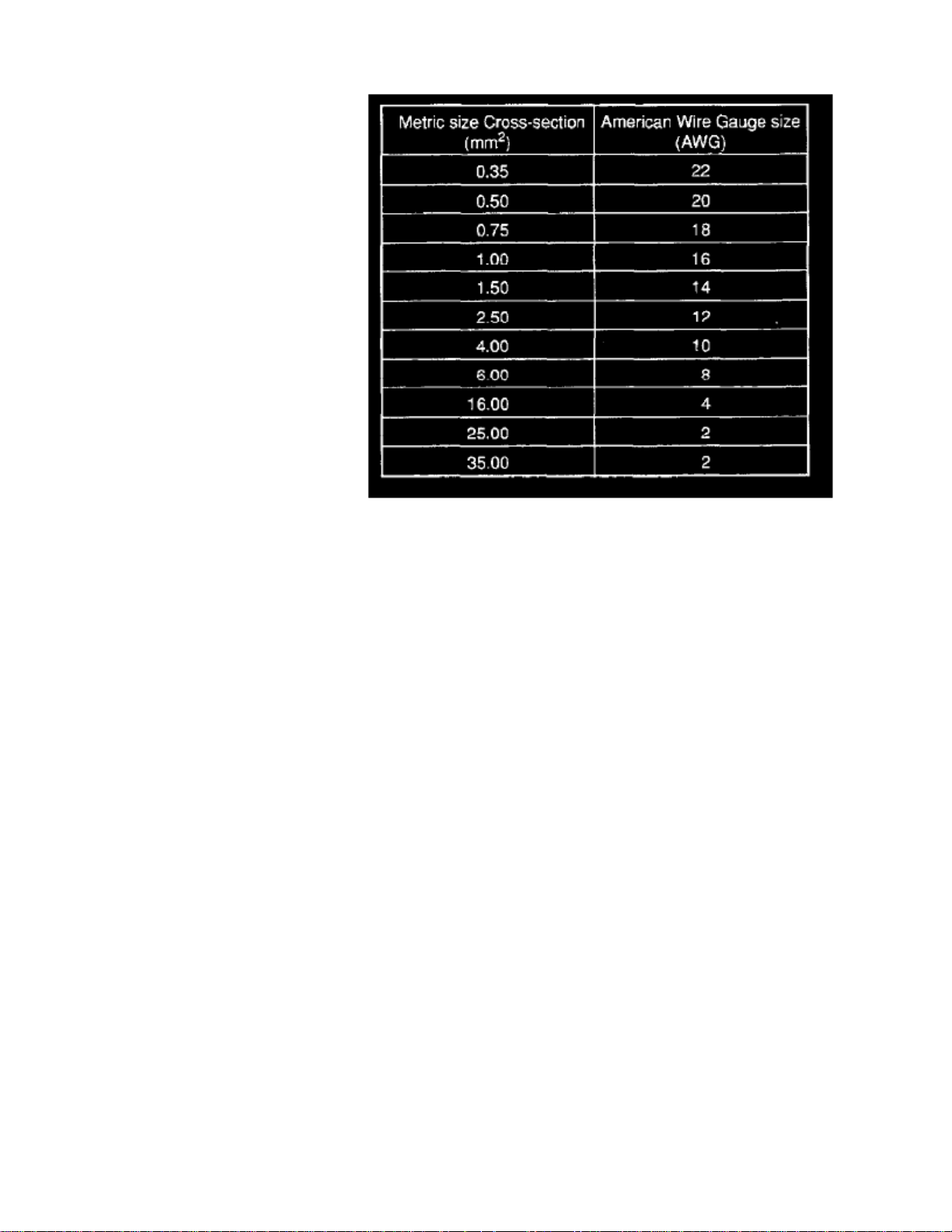
Wire Size Conversion
Wire Size Conversion Chart
Page 75

> Relays and Modules > Relays and Modules - Body and Frame > Power Door Lock Control Module > Component Information > Diagrams > Diagram Information and
Instructions > Page 63
Beetle L4-2.0L (AEG) (2000)
Wiring Diagrams identify wires by the metric wire size. Metric wire sizes indicate cross-sectional area in square millimeter (mm sq.). The chartbelow lists metric wire sizes and their equivalents in American Wire Gauge (AWG) sizes.
Page 76
Page 77

Page 78

> Relays and Modules > Relays and Modules - Body and Frame > Power Door Lock Control Module > Component Information > Diagrams > Diagram Information and Instructions > Page 64
Power Door Lock Control Module: Electrical Diagrams
For information regarding diagrams for the , please refer to Body and Frame Comfort System Diagrams With Power WindowsDoor Control Module
Driver
See: Body and Frame/Diagrams/Electrical Diagrams/Comfort System Diagrams Vehicles With Power Windows/Diagram 36/02 (Track1-14)
Passenger
See: Body and Frame/Diagrams/Electrical Diagrams/Comfort System Diagrams Vehicles With Power Windows/Diagram 36/06 (Track57-70)
Page 79

Page 80

> Relays and Modules > Relays and Modules - Body and Frame > Sunroof / Moonroof Module > Component Information > Diagrams > Diagram Information and Instructions
Sunroof / Moonroof Module: Diagram Information and Instructions
How to Find Wiring Diagrams
: Wiring Diagrams are classified by OE as belonging to one of three categories.NOTE
:These Three OE Categories Are:
1 - Standard Equipment2 - Engine Specific3 - System Specific and Optional Equipment (Common Systems)
Standard Equipment
This category includes equipment such as Instrument Cluster and Gauges, Headlights/Tail Lights/Turn Signals, Rear Window Defroster, Wipersand Washers, etc...
Standard equipment is found on all vehicles regardless of which engine or optional equipment is installed.
The Standard Equipment diagrams can be found at Power and Ground Distribution diagrams, or via a component name on the at the vehicle level diagrams.Master DiagramIndex
Engine Specific
This category includes components and systems circuits such as Starting and Charging Systems, Engine Controls, Ignition System, Fuel InjectionSystem, etc., which are unique to a specific engine.
Master Diagram Index
The Engine Specific diagrams can be found at Powertrain Management diagrams, or via a component name on the at thevehicle level diagrams.
System Specific and Optional Equipment
This category includes equipment such as Air Bag Systems, Anti-lock Brake System, Heated Seats, HVAC System, Comfort System, etc.. andprovides circuit details for those systems and components.
Master Diagram Index
See: Diagrams/Electrical Diagrams/Master Diagram Index
How to Read Track Diagrams
Page 81

> Relays and Modules > Relays and Modules - Body and Frame > Sunroof / Moonroof Module > Component Information > Diagrams > Diagram Information and Instructions
> Page 69
Beetle L4-2.0L (AEG) (2000)
Page 82
Page 83

> Relays and Modules > Relays and Modules - Body and Frame > Sunroof / Moonroof Module > Component Information > Diagrams > Diagram Information and Instructions
> Page 70
Beetle L4-2.0L (AEG) (2000)
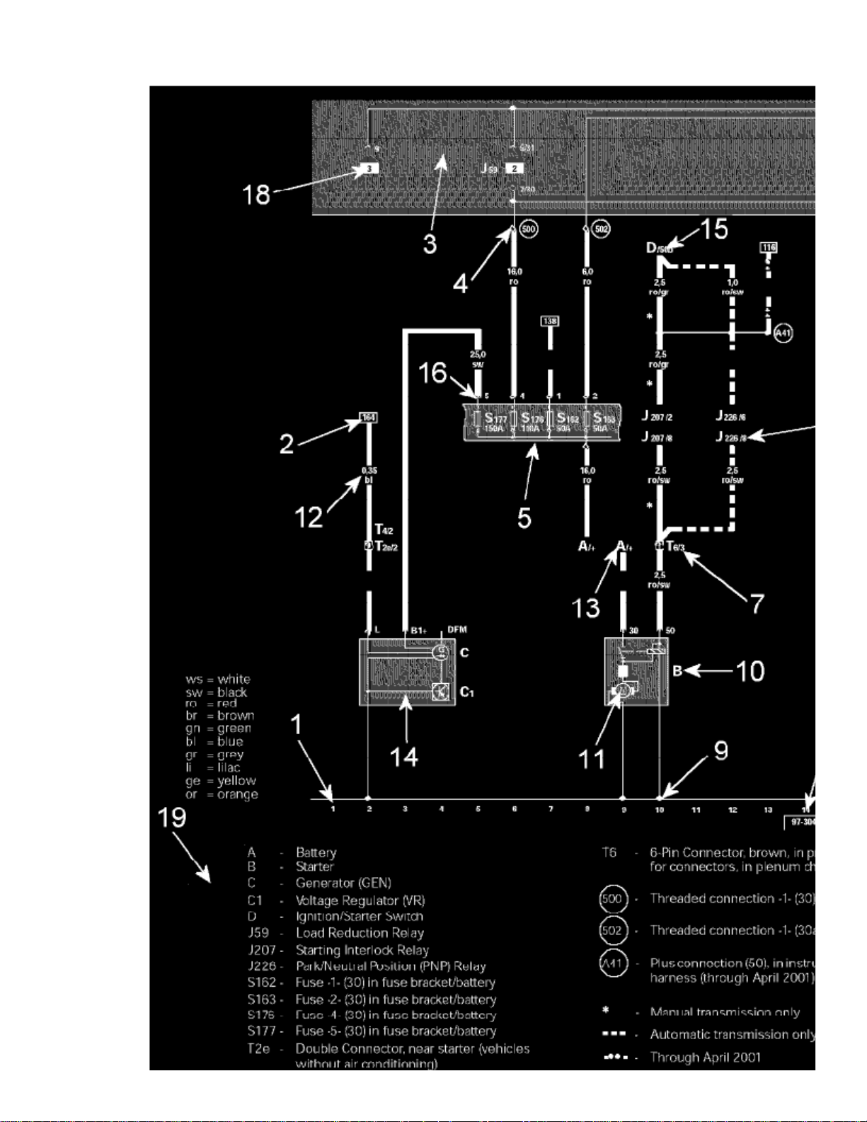
Wiring Diagram Layout
1 - Track Numbers
Imaginary grid lines extending from the numbers on the bottom of the diagram toward the top of the diagram. These imaginary grid lines are used foridentifying wire/circuit locations on diagrams.
2 - Reference of wire/circuit continuation to another diagram
Page 84

this
other
Number in frame indicates track where the wire/circuit is continued. For example, the reference in diagram is to track 164, which is on anotherdiagram. In the diagram showing track 164, the number in the frame for the same wire/circuit will change to the number 2, as that is the tracknumber for where the wire/circuit came from on diagram.this
Indicated by grey area.3 - Relay Panel -
4 - Diagram of threaded pin on relay panel
White circle shows a detachable connection.
5 - Fuse designation
Use legend at bottom of page to identify the fuse code.
6 - Arrow
Indicates wiring circuit is continued on the previous and/or next diagram.
7 - Wire connection designation in wiring harness
Location of wire connections are indicated in the legend.
8 - Terminal designation
Designation which appears on actual component and/or terminal number of a multi-point connector. For example: J226/8 = PNP Relay/terminal #8.
9 - Ground connection
10 - Component designation
Use legend at bottom of page to identify the component.
11 - Component symbols
12 - Wire cross-section size (in mm sq.) and wire colors
13 - Component symbol with open drawing side
Indicated component is continued on another wiring diagram.
15 - Reference of continuation of wire to component
For example: D/50b = Ignition/Starter Switch/terminal 50b.
16 - Relay panel connectors
Shows wiring of multi-point or single connectors on relay panel.
17 - Reference of internal connection continuation
Letters indicate where connection continues on the previous and/or next diagram.
18 - Relay location number
Indicates the physical location of the relay (by position number) on the relay panel. (For an actual relay panel image/view, see the component locationfor the relay in question.)
19 - Legend
Page 85

> Relays and Modules > Relays and Modules - Body and Frame > Sunroof / Moonroof Module > Component Information > Diagrams > Diagram Information and Instructions
> Page 71
Beetle L4-2.0L (AEG) (2000)
14 - Internal connections (thin lines)
These connections are not wires. Internal connections are current carrying and are listed to allow tracing of current flow inside components and wiringharness.
The legend contains the explanations for all of the designation codes used within the diagram. In all wiring diagrams the same component designation(code) is used for a particular component. For example, always "A" for the battery.
Following are the most common numbered/lettered circuits:20 - Power/Ground Distribution Circuit Identification
Terminal (circuit) 1
Ignition distributor low voltage (typically used as an Engine Speed (RPM) signal for the tachometer)
Terminal (circuit) 15
Switch Battery Positive Voltage (B+) from ignition/starter switch
Terminal (circuit) 30
Battery Positive voltage (B+), hot at all times
Page 86

Terminal (circuit) 31
Ground (GND)
Terminal (circuit) 50
Starter control; switched B+ from ignition/starter switch
Terminal (circuit) 56
Switched headlight B+ from light switch
Terminal (circuit) 58
Switched parking light, taillight. illumination B+ from light switch
Terminal (circuit) S (SU)
Key in ignition circuit; switched B+ from ignition/starter switch
Terminal (circuit) X
Load reduction circuit; switched B+ from load reduction relay
How to Use Track Diagrams
Page 87

> Relays and Modules > Relays and Modules - Body and Frame > Sunroof / Moonroof Module > Component Information > Diagrams > Diagram Information and Instructions
> Page 72
Beetle L4-2.0L (AEG) (2000)
Page 88
WHAT ARE TRACKS?
Page 89

> Relays and Modules > Relays and Modules - Body and Frame > Sunroof / Moonroof Module > Component Information > Diagrams > Diagram Information and Instructions
> Page 73
Beetle L4-2.0L (AEG) (2000)
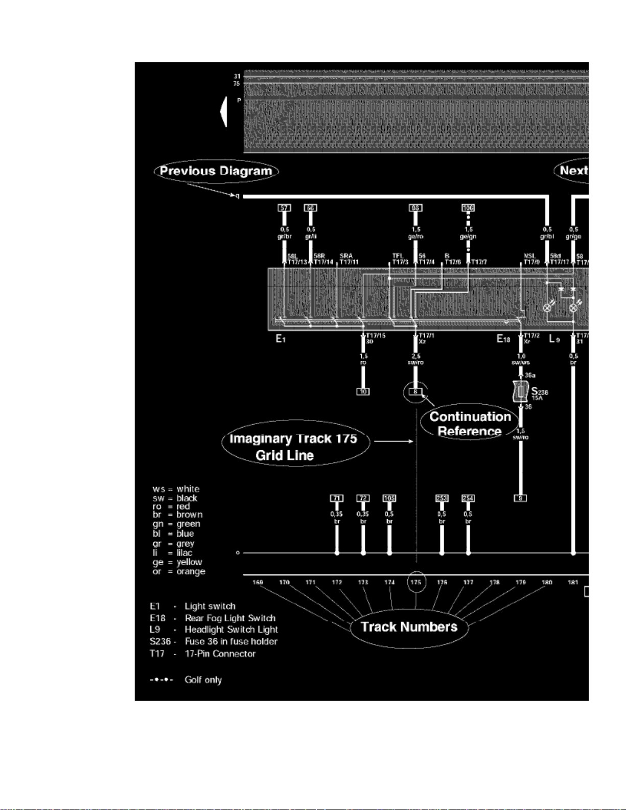
Tracks are navigational aids, like the grid lines on a map, but they are invisible on the diagrams. They are only identified by numbers at the bottom of thediagram.
The diagram wires/circuits are laid out over these imaginary vertical lines, and each diagram is identified by the range of tracks it is laid over, not by thediagram's contents (i.e. Track 1-14, Track 15-28, and so on).
HOW DO THE WIRES/CIRCUITS WORK WITH THE TRACKS?
Wires/Circuits that do not originate/terminate on the same diagram will have a notation of where they are coming from/going to at either end.
Wires/Circuits entering/leaving the diagram in a horizontal direction will pick up again on the previous/next diagram in the series.
However, wires/circuits traveling the diagram in a vertical direction are following the tracks, and when they enter/leave a diagram they could be skipping
Page 90
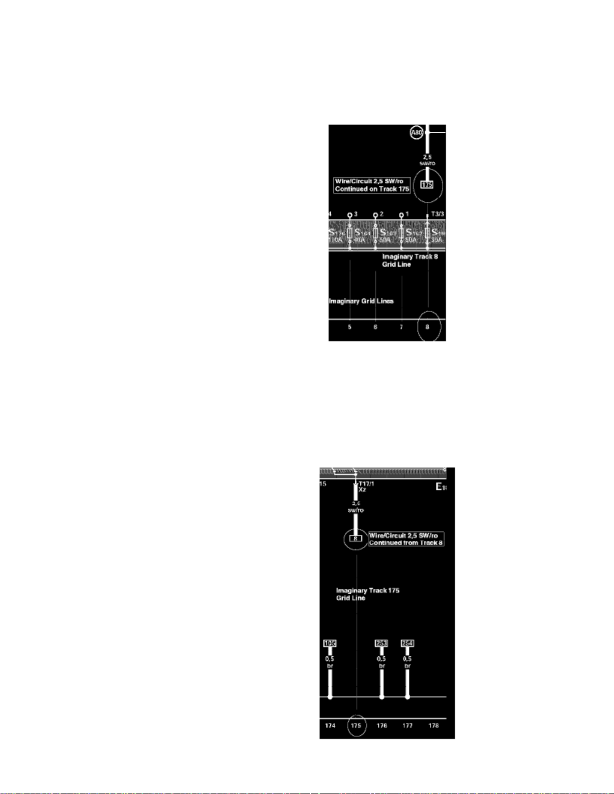
numerous diagrams in the series before picking up again on the destination diagram. When these wires/circuits enter or leave a diagram, the tracknumber of the diagram they came from/go to will be shown within a continuation reference frame/box.
HOW DO I NAVIGATE THE DIAGRAMS VIA THE TRACK NUMBERS?
Track 1-14
Assume you are tracing the wire/circuit identified by its size and color as on the diagram named Track 1-14. 2,5 sw/ro
This wire/circuit is running on track 8 of the diagram and terminates at the box labeled 175. To continue tracing this wire/circuit, you must now go toTrack 175, which is located within the diagram named Track 169-182.
But before going to the diagram named Track 169-182, again make note of the current track that you are leaving, which is Track 8.
Page 91

> Relays and Modules > Relays and Modules - Body and Frame > Sunroof / Moonroof Module > Component Information > Diagrams > Diagram Information and Instructions
> Page 74
Beetle L4-2.0L (AEG) (2000)
Track 169-182
After arriving at the diagram named Track 169-182, locate track 175 at the bottom of the diagram.
Follow the imaginary track 175 grid line toward the top of the diagram looking for a box labeled 8 (the track you are coming from).
2,5 sw/ro
When you locate the box labeled 8, you have picked up the continuation of wire/circuit and can continue to trace it until it terminates at eithera component or at yet another continuation reference box.
It is equally important that you always know the track that you are coming from as well as the one you are going to.NOTE:
Page 92
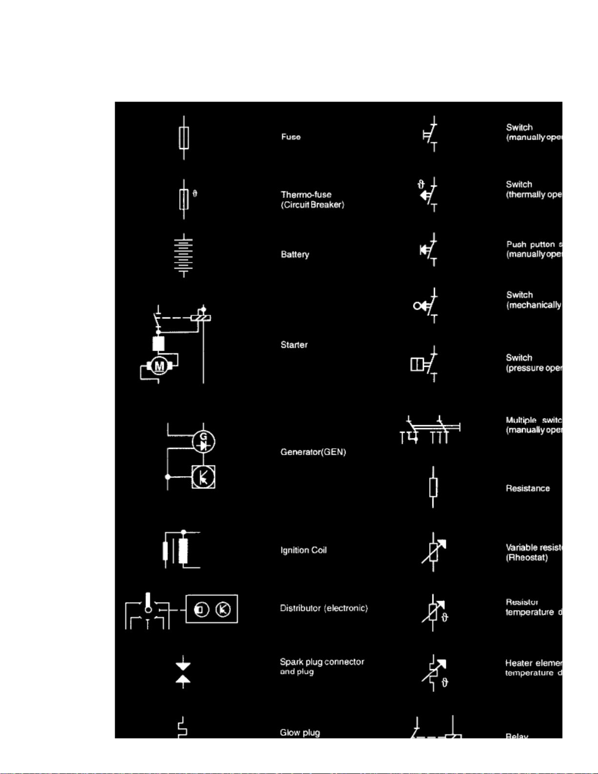
Symbols Used In Wiring Diagrams
Page 93

> Relays and Modules > Relays and Modules - Body and Frame > Sunroof / Moonroof Module > Component Information > Diagrams > Diagram Information and Instructions
> Page 75
Beetle L4-2.0L (AEG) (2000)
Part 1
Page 94
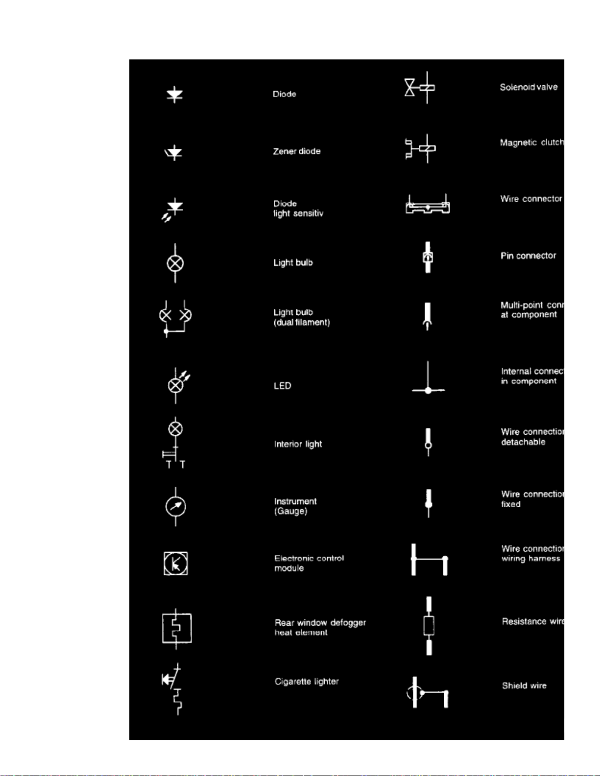
Page 95

> Relays and Modules > Relays and Modules - Body and Frame > Sunroof / Moonroof Module > Component Information > Diagrams > Diagram Information and Instructions
> Page 76
Beetle L4-2.0L (AEG) (2000)
Part 2
Page 96
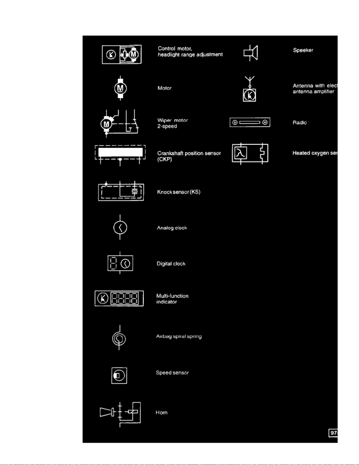
Page 97

> Relays and Modules > Relays and Modules - Body and Frame > Sunroof / Moonroof Module > Component Information > Diagrams > Diagram Information and Instructions
> Page 77
Beetle L4-2.0L (AEG) (2000)
Part 3
Circuit and Terminal Designations
Several wiring circuits in the vehicle's electrical system are identified with a number or letter designation. These circuits are identified the same in allwiring diagrams and are most commonly shown near the top of each page in the fuse/relay panel portion of the wiring diagram. The circuit designationsmay also be used to identify switch connector terminals (switch circuits). Following are the most common numbered/lettered circuits:
Terminal (circuit) 1
Ignition distributor low voltage (typically used as an Engine Speed (RPM) signal for the tachometer)
Page 98

Terminal (circuit) 15
Switch Battery Positive Voltage (B+) from ignition/starter switch
Terminal (circuit) 30
Battery Positive voltage (B+), hot at all times
Terminal (circuit) 31
Ground (GND)
Terminal (circuit) 50
Starter control; switched B+ from ignition/starter switch
Terminal (circuit) 56
Switched headlight B+ from light switch
Terminal (circuit) 58
Switched parking light, taillight. illumination B+ from light switch
Terminal (circuit) S (SU)
Key in ignition circuit; switched B+ from ignition/starter switch
Terminal (circuit) X
Load reduction circuit; switched B+ from load reduction relay
Wire and Fuse Color Code Identification
Wire Color Code Identification
ws = white
sw = black
ro = red
br = brown
gn = green
bl = blue
gr = grey
li = violet
ge = yellow
or = orange
Fuse Colors:
30 A - Green
25 A - White
20 A - Yellow
15 A - Blue
10 A - Red
7,5 A - Brown
5 A - Beige
3 A - Violet
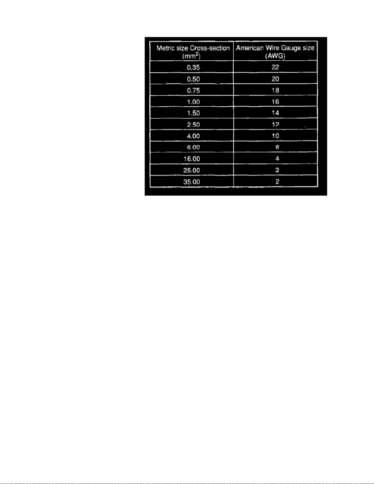
Wire Size Conversion
Wire Size Conversion Chart
Page 99

> Relays and Modules > Relays and Modules - Body and Frame > Sunroof / Moonroof Module > Component Information > Diagrams > Diagram Information and Instructions
> Page 78
Beetle L4-2.0L (AEG) (2000)
Wiring Diagrams identify wires by the metric wire size. Metric wire sizes indicate cross-sectional area in square millimeter (mm sq.). The chartbelow lists metric wire sizes and their equivalents in American Wire Gauge (AWG) sizes.
Page 100
 Loading...