

Page 1
VODAVI
VODAVI COMMUNICATIONS SYSTEMS
STARPLUS
1224EX
ELECTRONIC KEY SYSTEM
GENERAL DESCRIPTION
INSTALLATION AND
MAINTENANCE MANUAL
Page 2

h
STARPLUS 1224u(
KEY TELEPHONE SYSTEM
TABLEOFCON’TEN~
SECTION 100
100.1
100.2
100.3
SECTION 200
200.1
SECTION 300
300.1
300.2
300.3
300.4
300.5
300.6
300.7
300.8
300.9
300.10
300.11
300.12
300.13
300.14
300.15
300.16
300.17
300.18
300.19
300.20
300.21
300.22
300.23
300.24
300.25
300.26
300.27
300.28
300.29
300.30
300.31
INTRODUCTION
PURPOSE
REGULATORY INFORMATION (FCC,UL)
CANADIAN REGULATORY (CSA,OOC)
.................................................................................................
.................................................. l-2
............................................... 1-l
l-l
FEATURE DESCRlPTlON
ALPHABEIICAL USTING OF FEATURES
FEATURE INDEX
......................................................................................
...............................................
2-1
2-7
OPERATION
PLACING
ANSWERING
SPEAKERPHONE
VOLUME CONTROLS
MUTE BUTTON
BACKGROUND MUSIC .......... . .................................................................
PLACING OUTSIDE UNE ON HOLD
ANSWERING A RECALL ..........................................................................
FLASH .......................................................................................................
PBX TRANSFER
CALL PICKUP ...........................................................................................
PLACING AN INTERCOM CALL
ANSWERING AN INTERCOM CALL
CAMP ON .................................................................................................
ANSWERING A CAMP ON .......................................................................
LEAVING MESSAGE WAlTlNG INDICATION
ANSWERING MESSAGE,WAlTlNG INDICATION ................................... 33
CALLTRANSFER .....................................................................................
EXECUTIVE/SECRETARY TRANSFER
CONFERENCE .........................................................................................
DO NOT DISTURB ....................................................................................
QUEUING
STORING SPEED NUMBERS
LAST NUMBER REDIAL ........................................................................... 3-5
PAGING
CALL FORWARDING ................................................................................ 3-s
NIGHT SERVICE ....................................................................................... 38
SEillNG SYSTEM TIME AND DATE
ALARM ...................................................................................................... 36
ACCOUNT CODES ................................................................................... 3-6
PROGRAMMING FLEXlBLE BUlTONS
AN OUTSIDE CALL
AN OUTSIDE CALL.. ......................................................... 3-l
..................................................................................... 3-l
..............................................................................
........................................................................................
....................................................................................... 3-2
................................................................................................. 34
.................... . ............................................................................... 3-5
................................................................. 3-l
3-l
3-l
3-l
....................................................... 3-l
3-1
3-2
3-2
.............................................................. 3-2
........................................................ 3-2
3-2
3-2
.......................................... 3-2
3-3
.................................................... 3-3
3-3
3-4
.................................................................. 3-5
.......................................................
..................................................
3-6
38
SECTlON 400
409.1
466.2
466.3
GENERAL DESCRlPTlON
TECHNOLOGY ......................................................................................... 4-l
CAPACITY ................................................................................................. 4-l
SYSTEM COMPONENTS ......................................................................... 4-l
ELECTRICAL SPEClFlCATlONS .............................................................. 4-3
DIMENSIONS AND WElGHT ................................................................... 4-3
DIALING SPEClFlCATlONS ..................................................................... 44
ENVlRONMENTAL SPEClFlCATlON ....................................................... 4-4
Page 3

STARPLUS 1224EX KEY TELEPHONE SYSTEM
........................................................................................................
SECTION 500
500.1
500.2
500.3
500.4
500.5
500.6
500.7
500.8
500.9
500.10
500.11
500.12
500.13
500.14
500.15
500.16
500.17
500.18
500.19
500.20
500.21
RS232C PORT
. . . . . . . . . . . . . . . . . . . . . . . . . . . . . . . . . . . . . . . . . . . . . . . . . . . . . . . . . . . . . . . . . . . . . . . . . . . . . . . . . . . . . . . . . .
INSTALLATlCiN
SITE PLANNING .......................................................................................
UNPACKlNG THE KSU ............................................................................
KSU GROUNDING ...................................................................................
KSU INSTALIATION
KSU CABLING
UGHTNING PROTECTION ......................................................................
KEY TELEPHONE INSTALLATlON ..........................................................
WALL MOUNT KIT INSTALlATiON
PHONE BOX INSTALLATION
EXTERNAL MUSIC SOURCE
ALARM INSTALLATION
BATTERY BACKUP
UCTERNAL PAGING
LOUD BELL CONTROL/A-LEAD INDICATION
EMERGENCY TRANSFER
HEADSET INSTALLATION
POWER UP AND INSTALlATlON CHECKLlST
SIU MODULE INSTALlATION
RUC INSTALLATION
BAlTERY BACKUP UNIT
SMDR PRINTOUT
WIRING
......................................... ..” ........................................................
................................................................................
..........................................................................................
..... ..r..........................~
..................................................................
...................................................................
............................................................................
..................................................................................
.................................................................................
........................................
.......................................................................
.......................................................................
......................................
.................................................................
................................................................................
.........................................................................
.....................................................................................
......................
44
.
5-l
5-l
5-l
5-l
5-2
5-2
5-2
5-2
5-3
5b
5-3
5-3
5-3
5-4
5-4
5-4
5-4
5-4
5-5
5-5
5-7
5-8
SECTION 600
600.1
600.2
600.3
600.4
600.5
600.6
600.7
600.8
600.9
600.10
600.11
600.12
600.13
600.14
600.15
600.16
600.17
600.18
600.19
600.20
600.21
600.22
600.23
600.24
600.25
600.26
600.27
600.28
W’STOMER DATABASE PROGRAMMING
INTRODUCTION
DATABASE WORKSHEETS
DATABASE FlELDS
PROGRAM MODE ENTRY
INlTlALlZATlON ........................................................................................
STATION CLASS OF SERVICE
STATION PROGRAMMING.. ....................................................................
FLEXIBLE
FLEXIBLE
PAGE GROUPS
PICKUP GROUPS
PROGRAMMING
CO UNE GROUPS ...................................................................................
CO UNE DATA .........................................................................................
CO UNE RINGING ...................................................................................
FLASH TIMER ...........................................................................................
CO RING DETECT ....................................................................................
DIAL PULSE ..............................................................................................
SYSTEM DATA .........................................................................................
TIMERS .....................................................................................................
EXECUTIVE/SECRETARY ASSIGNMENTS
LOUD BELL CONTROL/A-LEAD INDICATION ........................................
PBX DIAUNG CODES ..............................................................................
ATTENDANT POSITION ...........................................................................
PRESET FORWARD RING TIMER..
PRESFT CALL FORWARD .......................................................................
CONFERENCE TIMER .............................................................................
SMDR
.......................................................................................
.....................................................................
..................................................................................
.......................................................................
................................................................
STATION NUMBERS ..............................................................
BUllONS.. ..............................................................................
........................................................................................
.....................................................................................
BASIC TELEPHONES/DSS CONSOLES..
.............................................
................... . ......................................
.................. 6-l 1
6-l
6-l
6-1
6-2
6-2
6-3
6-4
6-6
6-7
6-9
6-10
6-12
6-13
6-14
6-15
6-16
6-l 7
6-18
6-20
6-23
6-24
6-25
6-28
6-27.
6-28
6-28
6-28
JULY 1989
ii
Page 4
STARPLUS 1224M
KEY TELEPHONE SYSTEM
600.29
600.30
600.31
600.32
600.33
600.34
600.35
600.36
600.37
600.38
SECTION 700
700.1
700.2
700.3
700.4
700.5
SECTION 800
800.1
800.2
800.3
800.4
800.5 Irk
800.6
800.7
800.8
800.9
800.10
800.11
DATA BASE PRINTOUT..
.........................................................................
6-30
LCD DISPLAY ........................................................................................... 6-31
TOLL RESTRICTION TABLES..
STATION SPEED DIAL
..............................................................................
PULSE TO TONE SWITCHOVER
FLASH
WITH SPEED DIAL.. .................................................................... 6-33
NUMBERING PLAN.. ................................................................................
NIGHT SERVICE
SYSTEM SPEED DIAL
SEI-RNG
SYSTEM TIME AND DATE.. ..................................................... 6-34
.......................................................................................
..............................................................................
DATA FIELDS AND DEFAULT VALUES ..................................................
WORKSHEETS
DATABASE
.........................................................................................
PRINTOUT ......................................................................... .;. 6-42
................................................................
............................................................
6-32
643
6-33
6-33
6-34
6-35
6-36
SYSTEM CHECKOUT PROCEDURES
FUNCTIONAL TEST PROCEDURES .......................................................
PREUMINARY CHECKUST ..................................................................... 7-1
KEY STATION TESTING ..........................................................................
INTERCOM FUNCTIONS TEST ...............................................................
CO UNE FUNCTIONS TEST ....................................................................
7-1
7-2
73
7-5
MAINTENANCE AND TROUBLESHOOTING
GENERAL INFORMATION .......................................................................
PREVENTIVE MAINTENANCE .................................................................
TEST EQUIPMENT AND TOOLS ............................................................. 8-l
SPAREPARTS .......................................................................................... 8-l
FIELD SERVICE ENGINEERING .............................................................
FAULT
CLASSIFICATION.. ......................................... .m.. .......................... 8-l
SYSTEM FAILURES .................................................................................
POWER FAILURES.. ................................................................................. 8-2
KEY TELEPHONE FAILURES ..................................................................
CO/PBX UNE FAILURES .........................................................................
FEATURE OPERATION FAILURES .........................................................
POWER TEST ........................................................................................... 83
8-1
8-l
8-l
8-2
8-2
8-2
8-2
APPENDIX A
JULY 1989
SP-1224EX PARTS UST . . . . . . . . . . . . . . . . . . . . . . . . . . . . . . . . . . . . . . . . . . . . . . . . . . . . . . . . . . . . . . . . . . . . . . . . . . . A-l
. . .
III
Page 5
I .- -
_..
sTARPLus 1zaEx
KEY TELEPHONE SYSTEM
VODAVl COMMUNICATIONS SYSTEMS
For sales infomation call 1s (in Arizona call
94W971). Iln Canada ca!I yew distributor.
For technical
-1971). In Canada call your distributor.
support
call l-80&35&7279 (in Arizona call
Page 6
STARPLUS 1224EX
KEY TELEPHONE SYSTEM
1224EX ISSUE CONTROL
ISSUE
1
2
DATE
Feb 1968
July 1989
CHANGE
First draft
Add Canadian Regulatory lnforrnatbn
Add phone box, DSS console and BBU drawings
Page 7
.
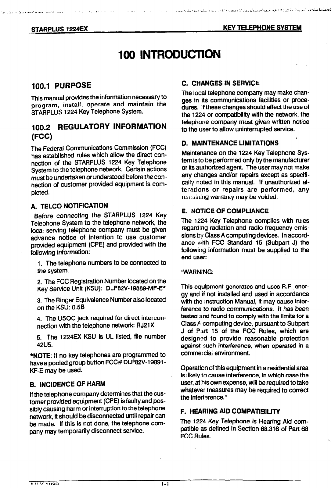
100.1 PURPOSE
This manual provides the information necessary to
program,
STARPLUS 1224 Key Telephone System.
100.2
install, operate and maintain the
REGULATORY INFORMATION
(FCC)
The Federal
has established rules which allow the direct connection of the STARPLUS 1224 Key Telephone
System to the telephone network. Certain actions
must be undertaken or understood before the connection of customer provided equipment is completed.
A. TELCO NOTlFlCATlON
Before connecting the STARPLUS 1224 Key
Telephone System to the telephone ne@ork, the
local serving telephone company must be given
advance notice of intention to use customer
provided equipment (CPE) and provided with the
following information:
1. The telephone numbers to be connected to
the system.
2. The FCC Registration Number located on the
Key Service Unit (KSU): DLP82V19889-MF-E*
3. The Ringer Equivalence Number also located
on the KSU: 0.56
4. The USOC jack required for direct interconnection with the telephone network: RJ21 X
5. The 1224EX KSU is UL listed, file number
42U5.
*NOE: If no key telephones are programmed to
have a pooled group button FCC# DLP82V19891KF-E may be used.
B. INCIDENCE OF HARM
If the telephone company determines that the cus-
tomer provided equipment (CPE) is faulty and possibly causing harm or interruption to the telephone
network, it should be disconnected until repair can
be made. If this is not done, the telephone company may temporarily disconnect service.
Communications Commission (FCC)
C. CHANGES IN SEFlVICIi
The local telephone company may make chan-
ges In its communications facilities or procedures. If these changes should affect the use of
the 1224 or compatibility with the network, the
telephone company must given written notice
to the user to allow uninterrupted service.
D. MAiNTENANCE LlMlTATlONS
Maintenance on the 1224 Key Telephone System is to be performed only by the manufacturer
or its authorized agent. The user may not make
any changes and/or repairs except as specifi-
colly noted in this manual. If unauthorized alterations or repairs are performed, any
re:z-‘aining warranty may be voided.
E. NOTICE OF COMPUANCE
The 1224 Key Telephone complies with rules
regarding radiation and radio frequency emissions by Class A computing devices.
ance with FCC Standard 15 (Subpart J) the
following information must be supplied to the
end user:
‘WARNING:
This equipment generates and uses R.F. ener-
gy and if not installed and used in accordance
with the instruction Manual, it may cause interference to radio communications. It has been
tested and found to comply with the limits for a
Class C computing device, pursuant to Subpart
J of Part 15 of the FCC Rules, which are
designed to provide reasonable protection
against such interference, when operated in a
commercial environment.
Operation of this equipment in a residential area
Is likely to cause interference, in which case the
user, at his own expense, will be required to take
whatever measures may be required to correct
the interference.”
F. HEARING AID COMPATlBlLlTY
The 1224 Key Telephone is Hearing Aid com-
patible as defined in Section 68.316 of Part.68
FCC Rules.
’
In accord-
Page 8
STARPLUS 1224EX
---
100.3 CANADIAN REGULATORY INFORMATION
Department of Communications (DOC)
Certification Number: 676 2581A
Load Number: 16
KEY TELEPHONE SYSTEM
NOTE: The Load Number (IN) assigned to
each terminal device denotes the percentage of
the total load to be connected to a telephone
loop which is used by the device to prevent
overloading. The termination on a loop may
consist of any combination of devices subject
only to the requirement that the total of the load
numbers of all the devices does not exceed 100.
Ancillary Equipment Number: CA21A
File Number: LB57228
A. NOTICE
The Canadian Department of Communications
label identifies certified equipment. This certification means that the equipment meets certain
telecommunications network protective, operationai and safety requirements. The Department
does not guarantee the equipment will operate to
the user’s satisfaction. Before installing this equipment, users should ensure that it is permissible to
be connected to the facilities of the local telecommunications company. The equipment must also
be installed using an acceptable method of connection. in some cases, the company’s inside
wiring associated with single line indiviiual service
may be extended by means of a certffied connec-
tor assembly (telephone extension cord). The customer should be aware that compfhnce with the
above condition may not prevent degradation of
service in some situations.
Repairs to certified equipment should be made
by an authorized Canadian maintenance facility
designated by the supplier.
Any repairs or alterations made by the’user to
this equipment, or equipment malfunctions,
may give the telecommunications company
cause to request the user to disconnect the
equipment.
Users should ensure for their own protection
that the electrical ground connections of the
power utility, telephone lines and internal metaflit water pipe system, if present, are connected
together. This precaution may be particularly
important in rural areas.
CAUTION: Users should not attempt to make
such connections themselves, but should contact the appropriate electric inspection authority
or electrician, as appropriate.
JULY
1989
l-2
Page 9
^
., .
STARPWS 1224EX
.-_.
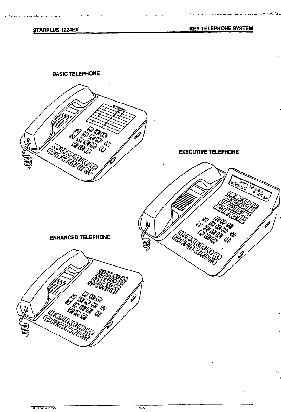
BAStC TELEPHONE
KEY TELEPHONE SYSTEM
.
EXECUTIVE TELEPHONE
ENHANCED TELEPHONE
0
Page 10
200 FEATURE DESCRIPTION
A-LEAD INDlCATlON
There are 4 contacts which may be indiviiualiy
programmed as either A-lead indication (to contrd
ancillary equipment) or Loud Bell Contrd. When
programmed as A-Lead indication &assigned to a
CO line, the corresponding contact will dose
whenever that CO line is accessed by a station.
ACCOUNT CODES
Account codes can be entered by the user during
a call; this Cod8 can be used with SMDR informa-
tion for billing purposes. it can be 8 digits in
length.
ALARM SIGNAUNG
The system can recognize either an open or dosed
loop from an extemai rday and transmit an aiarm
signai. This signal can be sent to all programmed
stations with either a single or repeated tone. The
type of alarm tone is selected in system program-
ming.
This feature can be used as an entry door alarm.
AU CALL PAGING
StatiOnS allowed t0 make pages may mak8 VOUCH
paging annOUnC8mentS to all idle stations, phone
boxes and extemai paging ports at th8 same time.
AUTOMATIC SELECTION
The us8r can select an outside line, intercom
station or speed diai button or dtai a feature &
automatically plaC8 the phone in the dialing
mode without pressing the ON/OFF button or
lifting th8 hand&.
AUTOMATlC PAUSE INSERTlON
If a ftash is programmed into syst8m and station
speed diai numbers, and last number red&l
numbers, a pause will automatically be inserted
after the flash.
ly inserted after a PBX dialing code has been
used & after a. pulse to tone switchover is
programmed into speed diai numbers.
BACKGROUND MUSIC
Key telephone & phone box users may receive
music over their speaker when an optional
mUSiC source has been Conn8Ct8d t0 the system. Th8 mUSiC can be Weed on or off and the
vdumeadjusted at each indiviiuai telephone or
phOn8 box The maximum loudness level can
be adjusted on the KSU.
Phone boxes that are denied DND in data base
programming, can receive music through their
speaker.
A pause will aiso be automatical-
ATTENDANT OVERFLOW
(Refer to Call Forward-Preset) System program-
ming allows the attendant station to b8
programmed so that if the attendant is busy or not
there, the tail will be automatically forwarded.to
another pred8t8rmin8d station after a
programmed period of time.
ATTENDANT POSlTlON
Any key t8f8phOn8 SUitiOn may b8 assigned as th8
system attendant. The assigned attendant will
receive unattended line recalls and will initiate
NIGHT SERVICE.
AUTOMATDC PRIVACY
Privacy is automaticaily provided on all calls. The
system may be programmed to eliminate privacy,
allowing another station to join in on existing CO
(outside) iin COnVerSatfOnS.
This feature can be allowed or denied on a per
station basis by programming.
BATIERY BACK-UP (MEMORY)
A long life lithium battery is provided inside the
KSU to prevent loss of system programming in
the 8V8nt of a pOw8r Outage Or the System
power being turned off.
BAlTERY BACK-UP (SYSTEM)
An OptiOnai battery package (BBU) & cabling
can be connected to the KSU to maintain complete system operation in the event of an AC
power failure. calls in progmss will continue
without interruption when commercial power
falls.
CALLING STATION INDICATOR
(Busy Lamp Field) Buttons programmed as sta-
tion buttons on a tei8phOn8 afS0 serve as a Busy
Page 11
Lamp Field to display the status of other
..4
telephones within the system.
CALL ANNOUNCING
Each telephone user can select the way that calls
to their phone are voice announced. By selecting
the 1°P position on the intercom signal switch, the
user can receive voice announced intercom calls
without the calling party hearing conversations in
progress. By selecting the “H” position, the user
can reply handsfree to voice announced intercom
calls. Basic model telephones cannot use the
handsfree (H) mode.
CALL FORWARD-STATION
Each key telephone user may direct intercom calls,
transferred outside lines and incoming outside
lines to be forwarded to another station in the sys-
tem. A forwarded call will signal In theTONE mode
regardless of the way the intercom signaling switch
was set. A station with calls forwarded to it can forward its calls to another station; a call will forward
in this manner an unlimited number of times;
howeverthe last station in a chain cannot use DND.
CALL FORWARD-PRESET
System programming allows incoming outside
lines, that are programmed to ring a particular station, to be forwarded to another predetermined
station after a programmed period of time. This
occurs when the station normally receiving the outside ring is busy or does not answer the call.
Preset forward can be chained an unlimited number of times. Each station in the system can have
a preset fotward station.
keysets without losing the call.
ferred to a busy station, that station will receive
muted ringing.
CAMP ON (Call Waiting)
A busy station may be alerted that an outside
line is on hold and waiting for them by pressing
the MSG/CP.ON button. The called station will
receive two muted rings, and a flashing CP.ON
button if the camp-on initiator is waiting to announce the transfer. The busy party can press
the MSG/CP.ON button. This will automatically
place on hold any outside line he’s currently
using and allow him to converse with the campon initiator.
CO LINE ACCESS
Each telephone can be programmed to be al-
lowed or denied an appearance to individual
outside lines or a pool of outside lines.
Telephones denied this appearance can have
that line transferred to them by another station
and the call will appear on the loop button.
Any station may be programmed to ring for any
combination of lines during the day and different
stations can be programmed to ring on those
lines at night.
CO LINE GROUPING
CO (outside) lines can be in one of up to 8
groups to separate line types such as local,
PBX, FX, etc. Stations are then individually assigned access to these lines via either a pooled
group key or by a direct line key.
If a line is trans-
.
CALL PICKUP (GROUP)
Stations can be placed in one, both or neither of 2
pickup groups. Stations within the same group
can pick up tone ringing intercom calls, recalling
or transferred CO line calls for another station, and
message wait call backs by dialing the pickup
code.
CALL TRANSFER
An outside line can be transferred from one keyset
toanother. By pressing the STATION button of the
desired party, or pressing the TFtANS/QUE button
and then dialing that 2 digit station number, unscreened or screened transfers with an an-
nouncement can be made. The line being
transferred rings on the keyset and gives a flash indication to the receiving party’s keyset. Several at-
tempts can be made to find someone at different
JULY 1989
2-2
CO LINE QUEUING
When all outside (CO) lines in a group are busy,
stations can be placed on a list awaiting that line
to become available. Users are signaled when
a line becomes available. If the waiting station
is busy when the queued CO line becomes
available, the station is placed at the bottom of
the queue list. If a station doesn’t answer a
queue callback within 15 seconds it will be
dropped from the queue list.
CONFERENCE
A) Multi tine
One internal station can engage in a conference
with 2 external parties. The internal station may
place the conference on HOLD by pressing the
HOLD button. The two external parties can be
Page 12
placed
in an unsupervised conference by ttie in-
itiator pressing the CONF button.
B) Add-On Conference
TWO
internai
StatiOnS
can engage in conference
with 1 external party or 3 internal parties can Set up
a conference. There is no limit to the number of
add-on conferences, except for the total number
of CO lines connected to the system.
COMMON AUDIBLE RINGING
(Loud Bell Control) Incoming CO line ringing can
be directed to relay controlled contacts. There are
4 sets of dry contacts that can be assigned to sta-
tions as LBC or to CO lines for A-lead indication.
An external power source and ringing device or
other ancillary is required.
DIAL PULSE/DTMF SIGNAUNG
Each outside line can be individually programmed
to provide dial pulse or DTMF tone sending.
DIAL PULSE TO TONE SWITCHOVER
The signaling on an outside line can be changed
from dial pulse to tone (DTMF). This allows lines
set for pulse signaling to use common carriers
which require DTMF signaling. This feature can be
stored and used with speed dial numbers.
DIRECT STATlON SELECT
The user with a flexible button assigned as a DSS
button on his key telephone can call an intercom
station by simply pressing the appropriate DSS
button. The called station is automatically signaled.
DO NOT DISTURB
Placing a key telephone in DND will eliminate in-
coming CO line ringing, intercom calls, CO line
transfers, All Call Page announcements and
Camp-Ons. Pressing the DND button twice while
the telephone is ringing will eliminate that ringing.
The secretary in an EXECUTIVE/SECRETARY pair
can override the Executive DND by using the
Camp-On feature. A station in DND can still use
the telephone to make normal outgoing calls. A
station can be denied this feature through
programming.
EMERGENCY TRANSFER
In the event of commercial power failure or central
processor failure, the system will automatically
connect the first 3 outside lines to single line
telephones which have been installed for that
purpose.
EXECUTIVE/SECRETARY TRANSFER
Four pairs of key telephones can be designated
as executive/secretary pairs. Whenever the executive phone is in DND or busy, transferred CO
lines and intercom calls will be directed to the
secretary station. If the secretary station is
busy, busy tone will be received by the calling
party. There are 3 combinations possible:
1. 4 Executive/Secretary pairs
2.’ 1 Executive with 14 secretaries ’
3. 1 Secretary for 14 Executives
The secretary station can signal the Executive
in DND by using the Camp On feature.
EXTERNAL PAGING
Any station that is allowed access to paging can
make voice paging announcements to the ex-
ternal paging port by either dlai code or direct
button access.
The external page port can be connected to a
two way paging system.
FLASH
The Fiash button is used to m-establish dial tone
or to transfer a PBX call. Flash can be
programmed in speed dial for Centrex feature
operation.
FLEXIBLE STATlON NUMBERS
The intercom number assigned to a station can
be changed without moving the telephone.
However station circuit 01 always remains the
programming station.
FLEXIBLE BUTTONS
On the Enhanced/Executive phones there are 6
fixed feature buttons and 22 flexible buttons.
The Basic telephone has 6 fixed feature buttons
and 6 flexible buttons. The flexible buttons can
be programmed in one of the following ways:
1. Outside line - automatically access assigned
line
2. Multi Function Key - the station user may
program his/her own phone to have DSS/BLF,
speed dial bin, page key or mute button. ..
Page 13
STARPLUS 1224EX
--
3. Pool Key - some or all outside lines can be
grouped; pressing this button gives access the
highest numbered unused, CO line in that group;
outgoing dialing only.
4. LOOP - used to answer transferred call on a line
for which a station user does not have a button
programmed on his phone.
HOLD PREFERENCE
Either exclusive hold or system hold can be
programmed to be the primary hold. A line on exclusive hold prohibiisanyonefrom picking up a call
placed on hold by another station.
An
outside line placed on system hold can be
retrieved by any other telephone in the system that
has access to that line.
INTERCOM SIGNALING
The key telephone user can select the method of
receiving intercom calls at their station. A slide
switch located on the telephone is used to select
the mode. The choices are:
KEY TELEPHONE SYSTEM
LAST NUMBER REDIAL
Permits the automatic redialing of the last phone
number dialed on an outside line including a
number in speed dial.
MEET ME PAGE
Users may answer a page call by going to the
nearest telephone, dialing a code and be connected to the calling party. A flexible button can
be programmed for one button answer by a sta-
tion user to a meet me page.
MESSAGE WAlTlNG
A station user who calls another station and
receives ringing, busy tone or DND tone and no
answer can activate a “message waiting” lamp
at that station to indicate this call. The station
user who missed the call can then press his
MSG/CP.ON flashing button and ring the party
leaving the message. Up to 5 messages may
be left at each phone. A station with a message
waiting can be reminded at a timed interval with
a tone.
1. Tone Ringing (l)
A standard tone ring notifies the party of an in-
coming call.
The called station answers by Ming the hand-
set.
2. Privacy (P)
The station user receives a tone burst and a
voice announcement over the speaker. The
microphone is deactivated, providing privacy.
The person who is called must lift the handset to
get the call or switch the selector to handsfree.
3. Handsfree (H)
The station user, upon hearing a tone burst &
voice announcement over the speaker, can
reply handsfree (“H” position).
(Basic model key telephones do not have this
feature.)
INTERNAL ZONE PAGE
Stations programmed to make pages can make
voice announcements to idle stations in both inter-
nal zones at the same time or to either one of the
2 internal zones separately. A flexible button can
be programmed for one button page operation by
the station user.
MUSIC ON HOLD
An optional music source can be connected
directly to the system to provide all calls on hold
with music.
The same source provides background music.
MUTE
A flexible button can be programmed to operate
as a mute key. During handsfree speakerphone
operation, the key telephone microphone can
be disabled for stations requiring priiacy of
transmission or in areas where there are high
ambient noise levels.
NIGHT SERVICE
The attendant places the system in night service
by pressing her DND button.* This allows
specific phones to ring at night that may or may
not ring during the day. A dial code is provided
for Universal Night Answer; a direct CO line button appearance or a loop key is required for this
feature.
l
The attendant does not have the DND feature.
OFF HOOK SIGNAUNG
.I1 II v 1989
24
Page 14
STARPLUS
1224EX
KEY TELEPHONE SYSTEM
If a station has been programmed to receive direct
outside line ringing and is busy on another call, that
station will receive muted ring to indicate another
call is ringing in.
ON HOOK DIAUNG
A telephone user can place calls without lifting the
handset and can monitor the call while the called
party’s phone is ringing or on hold. The receiver
must be lifted to converse when using a basic key
telephone.
ON UNE PROGRAMMING
Changes to the system data base with the exception of flexible button programming can be made
without interrupting normal system operation.
Programming is done at station port 01.
PBX DIAUNG CODES
Four 2 digit PBX access codes can be
programmed into the system. When an outside
line is selected and one of these codes is dialed,
toll restriction will be applied beginning with the
digit dialed after the code. If one of these codes is
not dialed, toll restriction doesn’t apply. This allows the dialing of PBX extensions 100, 110, 111,
etc. on an outside line. (The line must be assigned
as a PBX line.)
PAGE ACCESS RESTRICTION
Individual stations can be programmed to be al-
lowed or denied the ability to make page announcements.
PHONE BOX
A phone box may be substituted for a telephone
on a one for one basis. The phone box can be used
to receive intercom announcements and also
provide handsfree response. There is also a CALL
button which will signal all stations programmed to
receive alarm ringing. One of these stations can
respond to this signal by pressing the DSS/BLF
button or dialing the intercom number of the phone
box station. Two way conversation is then pos-
sible.
PREFERRED UNE ANSWER
A station with preferred lineanswer can answerany
assigned ringing outside line, line queues, outside
line transfers and transfer recalls by simply lifting
the handset or pressing the ON/OFF button. The
outside line button doesn’t have to be pressed
for automatic line answer.
PRIVATE UNE
A station can be programmed to have a private
line. A line designated as a private line can
transfer calls to other stations and can be forwarded to another station. When placed in
night service the UNA code will not pick up this
ringing line. A private line cannot have a preset
forward station.
REAL TlME
This hardware option allows the system time
and date to continue functioning in case of a
power failure.
Also provides the time source for information
used by SMDR and display phones.
SPEAKERPHONE
Enhanced & Executive model phones are
equipped with a unit that enables the telephone
to be used handsfree in two-way conversations
on both intercom and outside lines.
STATlON MESSAGE DETAIL RECORDING
A hardware option which allows connection to
an external RS232C compatible printer or call
accounting device. Programming allows the
system to track all calls, both incoming and outgoing, local and long distance; or just outgoing
long distance calls only. It is also possible to
print out data base programming with this
module. The system records calls by outside
line, number dialed, time of day, date, station
that placed the call and duration of Ihe call. The
output can be programmed for either a 29 or 80
character format.
Account codes may also be entered.
STATlON SPEED ‘DIAL
Each station user can program up to 20 in-
dividual speed dial numbers of up to 16 digits in
length. These numbers may contain pause
commands, flash commands and pulse to tone
switchover commands. Each one of these
commands takes up digit space. The numbers
are dialed by use of the SPEED button and a 2
digit code (W-tIS, 9oM)) or the station user can
program a flexible button as a speed button.
JULY 1969
2-5
Page 15
STARPLUS 1224EX
-
KEY TELEPHONE SYSTEM
Both the asterisk (*) and pound (#) are sent as
DTMF tones; this makes the speed dial feature
compatible with Centrex operation.
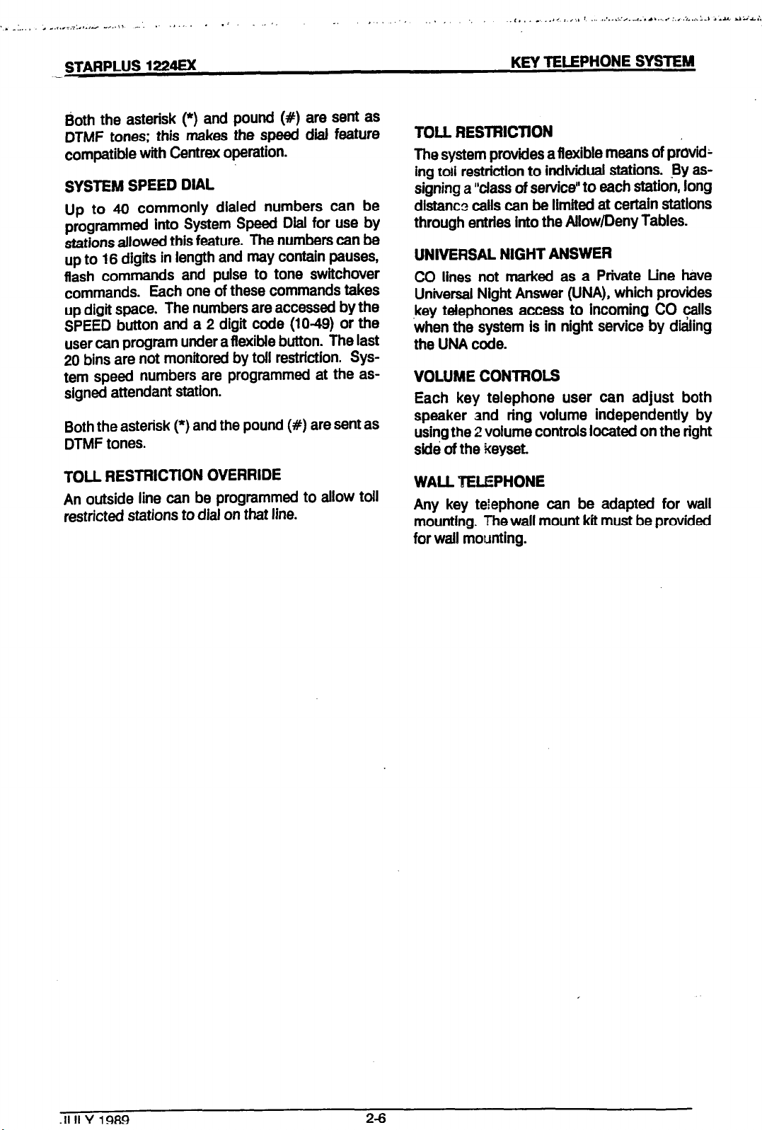
SYSTEM SPEED DIAL
Up to 40 commonly dialed numbers can be
programmed into System Speed Dial for use by
stations allowed this feature. The numbers can be
up to 16 digits in length and may contain pauses,
flash commands and pulse to tone switchover
commands. Each one of these commands takes
up digit space. The numbers are accessed by the
SPEED button and a 2 digit code (1049) or the
user can program under a flexible button. The last
20 bins are not monitored by toll restriction. System speed numbers are programmed at the assigned attendant station.
Both the asterisk (*) and the pound (#) are sent as
DTMF tones.
TOLL RESTRlCTlON OVERRIDE
An outside line can be programmed to allow toil
restricted stations to dial on that line.
TOLL RESTRlCTlON
The system provides a flexible means of providk
ing toti restriction to individual stations. By assigning a “class of service” to each station, long
dlstancs calls can be limited at certain stations
through entries into the Allow/Deny Tables.
UNIVERSAL NIGHT ANSWER
CD lines not marked as a Private tine have
Universal Night Answer (WA), which provides
key telephones access to incoming CO calls
when the system is in night service by dialing
the UNA code.
VOLUME CONTROLS
Each key telephone user can adjust both
speaker and ring volume independently by
using the 2 volume controls located on the right
sidb of the keyset.
WALL TELEPHONE
Any key telephone can be adapted for wall
mounting. The wall mount kit must be provided
for wail mounting.
.II II Y 19FN
2-6
Page 16
STARPLUS 1224EX
KEY lELEPHONE SYSTEM
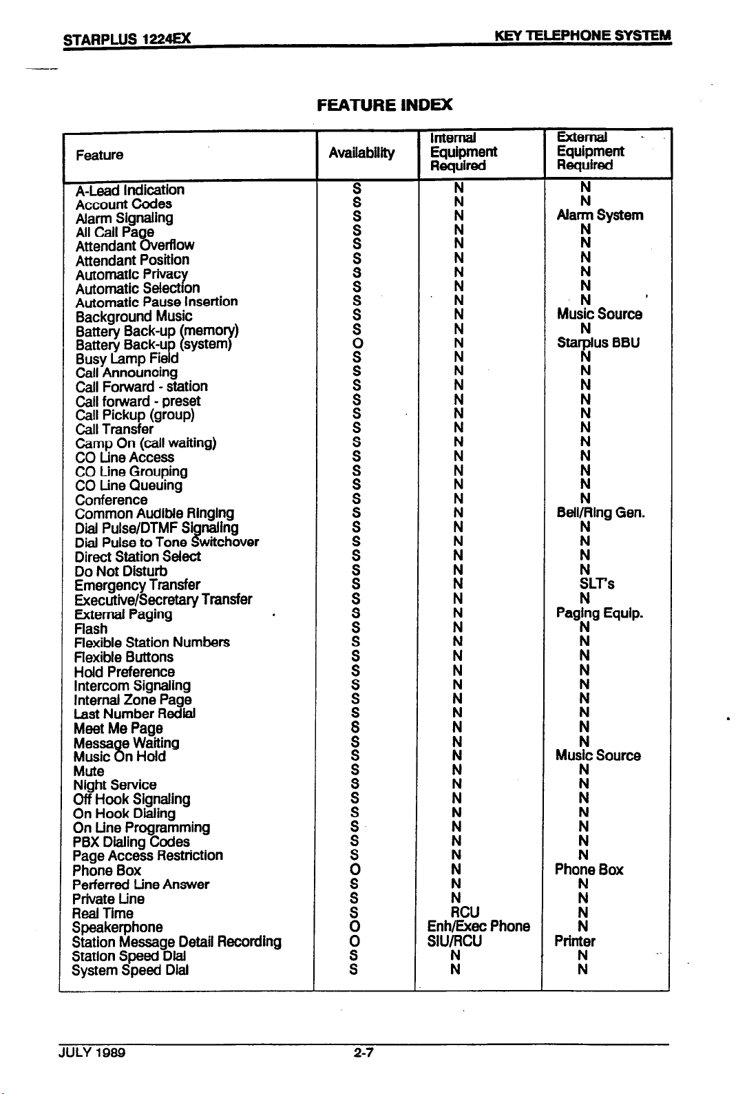
FEATURE INDEX
lntemal External .
Feature
A-Lead indication
Account Codes
Alarm Signaling
All Call Pa e
Attendant erflow
8v
Attendant Position
Automatic Privacy N
Automatic
Automatic Pause
SeleCtIOn
inSNtiOn
Background Music : Music Source
Battery Back-up memo
Battery Back-u
Busy Lamp Fie d Fl
system
I 7
P
)
Call Announcing :
Call Forward - station
Call forward - preset : Ii
Call Pickup (group) rl
Call Transfer :
Camp On (call waiting)
CO tine Access
CO Line Grouping
CO tine Queuing : 1
Conference
Common Audible Ringing
Dial Pulse/DTMF Si
Dial Pulse to Tone
naling
8
witchover
Direct Station Select
Do Not Disturb
Emergency Transfer
Executive/Secretary Transfer
External Paging
.
flash
flexible Station Numbers
flexible Buttons
Hold Preference
intercom Signaling
internal Zone Page
Last Number Radial Ii
Meet Me Page 1
Messa e Waiting
8
Music n Hold
Mute
Night Service
Off Hook Signaling
On Hook Dialing
On Line Programming
PBX Dialing Codes
Page Access Restriction
Phone Box
Perferred tine Answer
Private tine
Real Time
Speakerphone
Station Message Detail Recording
Station Speed Dial
System Speed Dial
Availability Equipment
pJ$ymnt
Required
: Ii
ki
: I! AaT System
:
:
Ii Ii
Ii
Ii
.N
I!
s,
Sta;us BBU
Ii
Ii
Iti
rl
: Fl
Ii
Ii N
:
Ii *@Tling Gen-
i
Ii Ii
:
Ii
bS
x
Ii
:
pagFlg Equip-
Ii
:
Ii
i
:
Ii
1
:
:
Ii
Ii
Music Source
:
Ii i
:
Ii i
:.
Ii Ii
:
Ii
N
Phone Box
:
1
:
RCU
Ii
~;r&‘f%~ Phone L!
t?
Printer
ss Ii Ii
’
.
.
Page 17
,. -
_ .
,.. ._ I 1. d.. .
. . . . .--. _ _._. 1.
._ .,... .-.-. _._.._.._ _
STAFIPLUS
1224Ex
KEY TELEPHONE SYSTEM
Internal
Feature
Availability
Equipment Equipment
Required
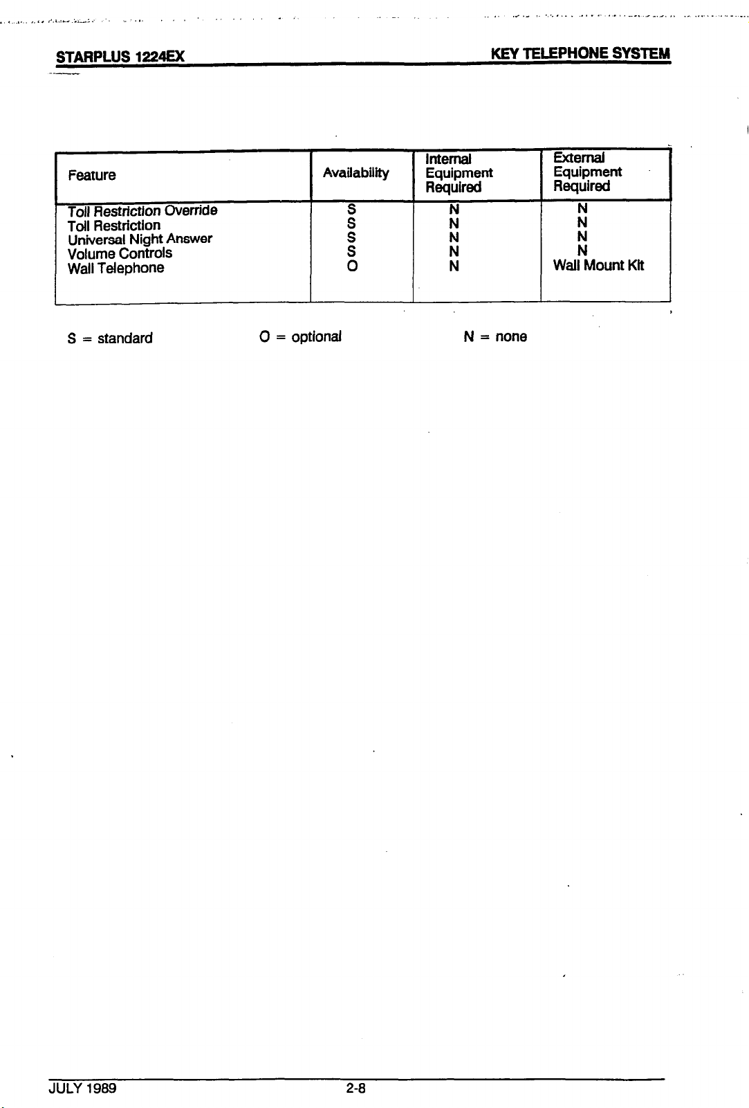
Toll Restriction Override
Toil Restriction
:
Ii
Universal Night Answer
Volume Controls
Wall Telephone
:
Ii I!
0 N Wail Mount Kit
S = standard 0 = optional N = none
External
Required
F!
JULY 1989
2-8
Page 18
STAFIPLUS
1224Ex
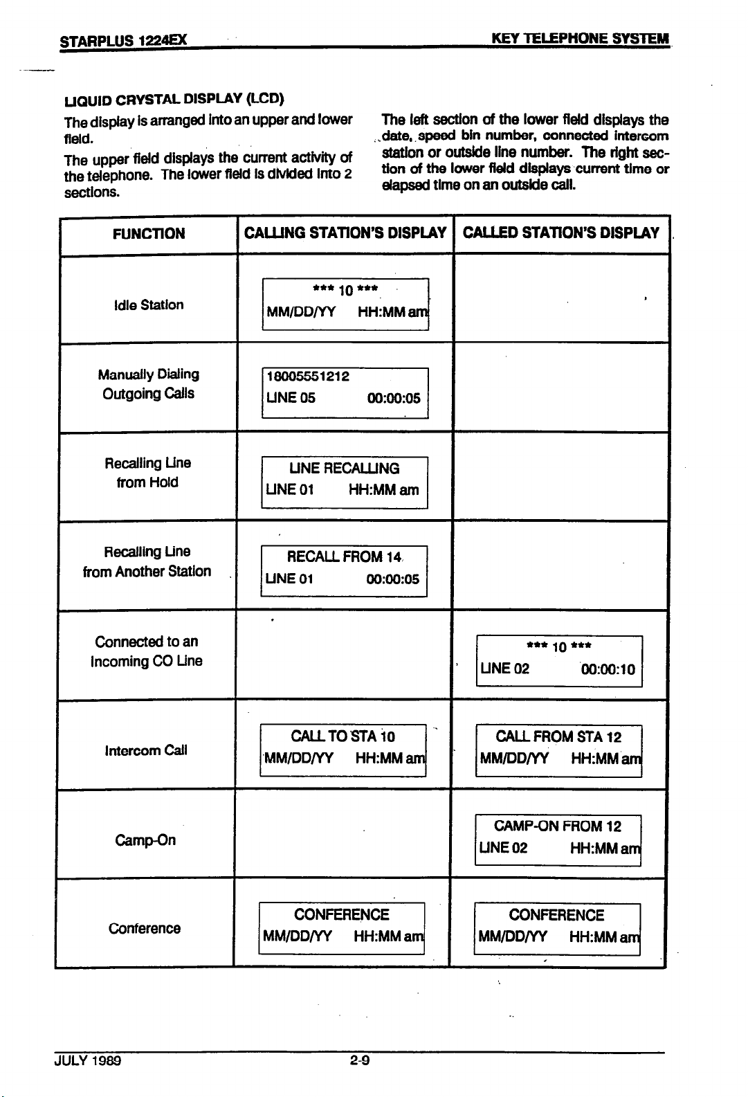
UQUID CRYSTAL DISPLAY (LCD)
The display is arranged into an upper and lower
field.
The upper field displays the current activity of
the tdephone. The lower field is dhkkd into 2
sections.
KEY TELEPHONE SYSTEM
The left sectIon of the lower field displays the
date, .speed bin number, connected intercom
station or outside line number. The right settion of the lower field displays-current time or
elapsed time on an outside call.
FUNCTION
Idle Station
Manually Dialing
Outgoing Calls
Recalling Line
from Hold
Recalling Line
from Another Station
CALLING STATION’S DISPLAY
CALLED STATION’S DISPIAY
Famj ’
-1
pLT%q
-1
.
Connected to an
Incoming CO Line
Intercom Call
Camp-On
Conference
jiii?Yq
.--I-. vllq
pz=Ezj
Page 19
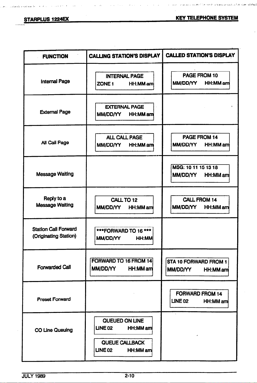
FUNCTION
internal Page
External Page
All Call Page
Message Waiting
CALJJNG STATION’S DISPLAY CALLED STATION’S DlSPLqY
Reply to a
Message Waiting
Station Call Forward
(Originating Station)
Forwarded Call
Preset Forward
CO Line Queuing
JULY 1989
2-10
Page 20
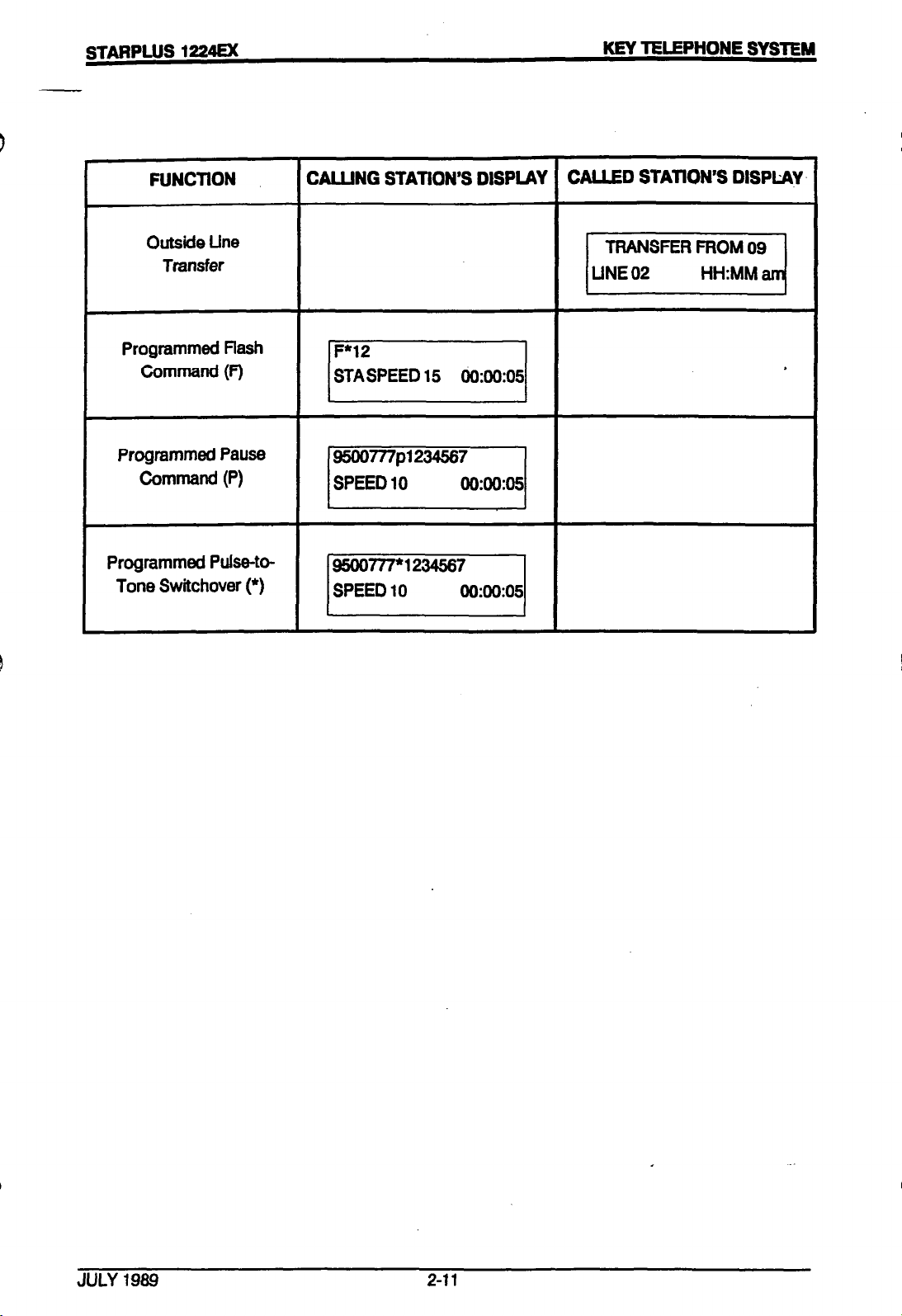
FUNCTION
Outside Line
TRNlsfer
Programmed flash
Command (F)
Programmed Pause
Command (P)
Programmed Pulse-to-
Tone Switchover (*)
CALLING STATION’S DISPLAY CALLED STATION’S DISPLAYS
JULY 1989
Z-11
Page 21
‘.. .
I . . , I , , ‘. . ,_, . . . . ...’ , ,.,.. .,I .-.‘L-,. .1&;,&&
STARPLUS 1224EX
300 OPEFWlON
For some features there is more than one way to
use the feature depending on how the telephone
is programmed. Both options will be listed.
300.1 PlAClNG AN OUTSIDE CALL
(Automatic Line Selection)
. Press outside line button.
. ON/OFF button will light & you will hear
dial tone.
Dial desired party.
.
When called party answers, lift handset to
.
converse or use speakerphone.
300.2 ANSWERING AN OUTSIDE
CALL
Lift handset.
.
KEY TELEPHONE SYSTEM
-
300.5 MUTE BUlTON (optional)
. Provides privacy during speakerphone
or handset operation by disabling the q
microphone.
. If you have a programmed mute button,
press while off hook to activate. (LED
lights)
. Press again to deactivate. (LED extin-
guishes)
300.6 BACKGROUND MUSIC
tional)
. Press 8 on the dial pad (music is heard).
. Press 8 again and music is discon-
tinued.
(op-
.
.
300.3
.
.
.
.
300.4
.
.
Press slow flashing outside line button.
(If your phone has been programmed with
Preferred Line Answer, you may answer
an outside line by just lifting the handset.)
SPEAKERPHONE (optional)
Press station key of desired party OR
Press available outside line button & dial
number.
Speakerphone is activated.
Press ON/OFF button to end call.
VOLUME CONTROLS
There are 2 volume control wheels on the.
rfght side of the key phone. Rotating the
wheel toward you will decrease the
volume.
Front wheel - voice, background music &
speakerphone.
e (When you pick up the handset or press
the ON/OFF button, music is discontinued automatically)
300.7 PLACING OUTSIDE LINE ON
HOLD
.
If your system is programmed to have
exclusive hold preferred, press HOLD
button once for exclusive hold and
twice for system hold.
If your system is programmed to have
.
system hold preferred, press HOLD
button once for system hold and twice
for exclusive hold.
300.8
ANSWERING A RECALL
.
When an outside line has remained on
hold for an extended period of time, you
will be reminded with a recalling rfng.
Press outside line button flashing at
very fast rate.
Lift handset to converse.
.
Back wheel -tone ringing volume
JULY 1989
3-l
Page 22

STARPLUS 1224EX
--
300.9 FLASH
Disconnects present outside line reseizes
.
outside line dial tone. When connected to
an outslde line, press FLASH button.
x10.10 PBX TRANSFER
While connected to an outskfe line (PBX),
.
press FLASH button Receive PBX transfer
dial tone
KEY TELEPHONE SYSTEM
tone ringing & your HOLD button will
slow flash. Lift handset or press
ON/Off button to answer. Hang up to
end call.
.
P mode, you will hear 3 bursts of tone
& a one way announcement. The
HOLD button will slow flash.
.
H mode, you will hear 3 bursts of tone
and an announcement Reply harbdsfree or lift handset for privacy.
. Dial PBX station number
Hang up to complete transfer
.
300.11 CALL PICK-UP
You must be in the same pick-up group as
.
the ringing telephone to pick up the call.
Tone ringing intercom calls only can be
picked up.
You hear an unattended phone ringing.
.
. Llft handset and dial 6.
You will be connected to the calling party.
.
300.12 PLACING AN INTERCOM CALL
.
Press station key of party you wish to call
l
(if programmed at your phone). OR
. Lift handset & dial station number (10-33).
. You will hear:
- Ringing if called station is In ‘T’ answering mode.
- 3 bursts of tone lf called station is in VP
or “PI position.
- Lift handset or use speakerphone when
tone bursts stop.
. Hang up to end call.
300.13 ANSWERING AN INTERCOM
CALL
With your Intercom signal switch In the:
. T mode, you will hear repeated Intercom
NOTE: If you have a programmed statlon button for the calling party, that button will flash.
you receive a call from a phone box, you must
press that station button to answer the call.
.__
300.14 CAMP ON
. You call a station that Is busy & wish to
alert them to your call,
. Press the MSG/CP.ON button twice.
. Called station will receive two bursts of
ringing.
. Walt for their response.
NOTE: If a station is in DND, only the attendant
can camp-on.
300.15 ANSWERING A CAMP ON
. If you are on a connected call, hear 2
bursts of muted ringing & your
MSG/CP.ON button is flashing, you
have a call waiting for you.
. To answer, press the MSG/CP.ON but-
ton. Any .outslde line you are connected to will be placed on hold. You
may converse with the station placing
the call.
300.16 LEAVING A MESSAGE WAITING INDlCATlON
Up to 5 messages can be left at any one key sta-
t&n.
.
If
JULY 1969
3-2
Page 23
_ _.., ‘.I.:.-.... I,..^ .,,
.‘:. .
. , ., .a .I’
_.
“.‘,,... ,._ ‘.?’ : . .,I .,.L-I. ~.~.i;.~A#L+i,..i
STARPLUS 1224EX
--
if you diai a station that is busy, unat-
.
tended or in DND, you can leave a
callback message indication.
. Press the MSG/CP.ON button once.
called party’s MSG button will slow ffash.
.
. Hang up.
300.17 ANSWERING A MESSAGE
WAITING INDICATION
The first message left will be the first one called.
if your MSG/CP.ON button is flashing at a
.
slow rate, you have a message waiting for
you.
Pick up handset.
.
Press flashing MSG/CP.ON button.
.
Station that left message will be signaled
.
with tone ringing.
if called station doesn’t answer, press
.
MSG button once to leave message.
KEY TELEPHONE SYSTEM
UNSCREENEDTRANSFER
Once the called exlension begins to
l
signal, hang up to transfer the caii.
(Recall timer starts.)
TRANSFER SEARCH
When attempting to locate a party, you
.
can press a station button to signal a
station.
if the party is not located, press
another station button to continue the
search. OR
. Press the TRANS button & dial the sta-
tion number. if the party is not located,
press the TRANS button again & dial
another station to continue the search.
. When the called party answers, hang
up to complete the transfer.
ANSWERING A SCREENED TRANSFER
. Your intercom will be signaling accord-
ing to the intercom signal switch posi-
tion.
. Answer the intercom & receive transfer
notice.
300.18 CALL TRANSFER
. Outside lines can be transferred from one
phone to another within the system.
The transfer can be either screened (an-
.
nounced) or unscreened to either an idle
or busy station.
SCREENED TRANSFER
. While connected to an outside line, press
station button where caii is to be trans-
ferred (ii programmed on your phone) OR
. Press TRANS button & diai station number
(1033).
The called extension signals according to
.
the intercom signal switch position.
. When that extension answers, announce
the transfer.
‘ Hang up to complete transfer.
. Press the outside line button or loop
button flashing on hold.
300.19 EXECUTIVE/SECRETARY
TRANSFER
if you are designated the EXECUTIVE
.
station &your phone is busy or in DND,
ail calls will be routed to the
SECRETARY station.
if you are the designated SECRETARY
.
station, you can signal the EXECUTIVE
that is busy or in DND by using the
Camp On feature.
300.20 CONFERENCE COMBINATIONS
. 2 internal and 1 external or 3 party in-
ternai - Add On Conference 1 internal
and 2 externai - Multi Line Conference
ESTABLISHING A CONFERENCE
A maximum of 3 parties can be included in a
conference.
.I111 Y 198!3
33
Page 24
.--
l Lift handset.
. seiect intercom station or dial desired out-
side party.
When called party answers, press CONF
.
button.
Add next conference party by selecting
.
another outside line or intercom station.
When patty answers, press CONF button.
d
All parties are connected.
.
EXITING A CONFERENCE (controller only)
There are 3 methods of exiting a conference:
Press the ON/OFF button to ON & replace
.
handset (to monitor a conference).
. Press HOLD button to place outside par-
ties on hold. Hold timer starts. If one of
the 2 parties is internal that party will be
dropped.
TERMlNATlNG A CONFERENCE
. Replace handset or push ON/OFF but-
ton to off. You must be actively in the
conference.
300.21 ACTIVATING DO NOT DIS-
TURB .
. If you have been given the ability to
place your phone in Do Not Disturb,
press the DND button (DO NOT lift
handset). DND button lights steady.
. You can press the DND button while
your phone is ringing & stop the ringing.
REMOVING DO NOT DISTURB
. Remain on-hook.
. Press DND button.
. The button LED extinguishes.
300.22 QUEUING
. Press CONF to leave the other conference
parties still connected in an unsupervised
conference. CONF button will flash &
timer will start. There will be a warning
tone before the other parties are dropped.
RE-ENTERING A CONFERENCE
. When the controller m-enters the con-
ference, the disconnect timer is reset.
.
Lift handset to m-enter a monitored con-
ference.
. To m-enter a conference placed on hold,
repeat steps for establishing a con-
ference.
.
To re-enter an unsupervised conference,
lift handset (multi-line).
.
To re-enter an unsupervised conference,
lift handset & press flashing CONF button
(add-on).
6 A station can queue only 1 line at a time.
. You see that a particular outside line is
busy & wish to be placed on a list wait-
ing for that line to become available.
. Lift handset.
. Press desired busy outside line button.
. Press QUE button.
0 Hang up.
TO CANCEL A QUEUE
. Lift handset or press ON/OFF button.
. Press QUE button.
. Dii tone will be heard.
ANSWERING A QUEUE
. You hear ringing &an outside line of the
line group you queued is slow flashing.
. CONF button lights steady & you hear
confirmation tone.
JULY
1989
34
. Ltfthandset. ,
.-
Page 25
-. )
, , , .,
L ..I# : ,.: Jh .I..,
STARPLUS 1224u(
--
Press flashing outside line button to
.
answer.
. (If your station has been programmed for
Preferred Line Answer, you will have the
line automatically upon lifting the handset.)
308.23 STORING SPEED NUMBERS
Press SPD button. .
Press asterisk (*) key once.
Dial speed bin location. 0099, 99-99 =
station speed numbers; 1049 = system
speed numbers.
Select desired outside line or one will be
chosen automatically.
Dial telephone number.
Press HOLD button.
KEY TELEPHONE SYSTEM
300.25 PAGING
. Stations off-hook or in DND will not hear
the page.
Lift handset & dial 2 digit paging code
l OR
Press programmed button.
.
Speak in normal tone of voice to deliver
.
message.
- 70 Internal All Call
- 71 Internal Zone 1
- 72 Internal Zone 2
- 73 External Zone
- 74AllCall
. Hang up.
MEET ME PAGE
. You wish to have another party call you.
Hang up.
- Dialing an * initiates a pulse to tone
swftchover.
_ Dlaling the TRANSKIUE during number
storage inserts a pause.
- Pressing the FLASH key inserts a flash
into the speed number.,
_ Pressing the CONF button will program
a “No Display’.
DIALING A SPEED NUMBER
If no outside line has been specified In
.
programming, one will be chosen
automatically or you can choose one now.
. Press SPD button & d&l bin location. OR
Press programmed speed bin button. CIO-
.
99,99-99 are station speed numbers; lo49 are system speed numbers.
When called party answers, pick up hand-
.
set or use speakerphone.
. Pick up handset & dial “74” or press
programmed button.
. Request that party meet you on the
paw
. DO NOT hang up; wait for the re-
quested party to answer.
ANSWERING A MEET ME PAGE
. Go to the nearest keyphone & dial “75”
or press preprogrammed button.
. You will be connected to the party that
paged YOU-
306.26 CALL FORWARDING (Sta-
tlon)
If you have been given the ability to for-
.
ward your calls:
.
Lift handset or press ON/OFF button.
Press FWD/DND button.
.
300.24 LAST NUMBER REDIAL
Press pound (#) key.
.
. Thelast numberdialed overan outsideline
will be automatically red&led.
JULY 1989
3-5
.
Press station button or dial intercom
number, within 5 seconds, where your
calls are to be forwarded.
.
Hang up.
Page 26
STARPLUS 1224EX
KEY TELEPHONE SYSTEM
TO REMOVE CALL FORWARDING
Lift handset or press ON/OFF button.
.
. Press FWD/DND button.
Press your own station button OR
.
. Dial your own intercom number.
. Hang up.
300.27 NIGHT SERVICE
Attendant presses DND button at that sta-
.
tion.
To remove, press DND button again.
.
NOTE: Attendant does not have DND feature.
300.28 SETTING SYSTEM TIME AND
DATE
Set at programmed attendant station.
300.29 ALARM
If you hear alarm signals on your telephone:
. Reset alarm condition.
, Go off-hook.
. Dial “9”.
. If you hear alarm signals on your
telephone, it may be a signal from a
phone box.
. Press station button programmed for
that phone box.
NOTE: If no station button has been
programmed, you may dial the phone box intercom number to answer the call.
,
300.30 USiNG ACCOUNT CODES
You are on an existing call.
.
. Press SPD button.
. Press asterisk (*) once.
. Dial “50”.
. Enter date & time as follows
YYMMDDHHMM
- W=year80-99
- MM = menthol-12
- DD = day0131
- HH = hour 00-23
- MM = minute 00-59
. Press FWD/DND button.
. Dial account code up to 8 digits. vhe
other party will not hear the digits being
dialed.)
NOTE: If the account code is less than 8 digits,
d&l an * to indicate account code entry if
finished.
300.31 TO PROGRAM FLEXIBLE
BUlTONS
Press asterisk (*) once.
l
. Press button to be programmed (it
must have been programmed in the
data base as a flexible button).
Dial desired code.
.
. Press HOLD.
JULY 1989
3-6
Page 27
,. .,
STARPLUS 1224EX
--
BUTI-ON PROGRAMMING CODES
DSS/BLF
Speed Bin
1033
SPD plus 2 digit number
00-09, go-99 = station speed
1049 = system speed
Mute 40
Paging:
internal Zone 1 71
Internal Zone 2
Internal All Call
External Zone
System All Call
Meet Me Pge Ans
72
70
73
74
75
NOTE: The speed bin must be programmed with
a number before a flexible button can be assigned
as a speed button.
KEY TELEPHONE SYSTEM
JULY 1989 3-7
Page 28
.STARPLUS 1224u(
400 GENERAL DESCRIPTION
400.1 TECHNOLOGY
The STARPLUS 1224EX Key Telephone System is
a microprocessor controlled soiid state electronic
switch which distributes communications in a
blocking format. Ail control, switching and interface circuitry is condensed onto 2 single printed
circuit boards (PCB) located inside the key service
unit (KSU). Refer to Figures 4.2 and 4.3.
Switching is accomplished through an unbalanced
space division type CMOS matrix that provides
voice path connection for 12 central office lines, 24
key telephones and 8 intercom channels.
The central microprocessor is a Z-88 and controls
the communications between slave microprocessors located in each key telephone.
The 1224 KSU contains all system memory which
is composed of 64K of Read Only Memory (ROM)
and 16K of Random Access Memory (RAM). The
RAM is subdiviied so that 8K is used as CPU
(Central Processor Unit) working area and 8K is
used for customer data base. The customer data
base memory is protected from loss by a long life
lithium battery. A Program Module contains the
operating instructions for the system. This module
can be easily removed and replaced which allows
for easy upgrading of software features.
The system power is regulated by a switching
power supply. This technology provides high efficiency with low heat. A shielded transformer converts the 117 VAC into logic voltages on a separate
power supply PCB mounted within the KSU
cabinet. Each key telephone contains a
micropr
tiviiand to control lamp (LED) indications. A builtin speaker permits voice or tone calling to the
station.
Basic, Enhanced and Executive model key
tdephones are ail equipped with 6 feature buttons.
The Basic phone has 6 flexibie buttons in addition
and the Enhanced and Executive phones have 22
flexible buttons.
ocessor & circuitry to monitor button ac-
KEY TELEPHONE SYSTEM
In addition the Enhanced and Executive Models
have speakerphones.
telephone is also equipped with an LCD as
standard equipment. A 3 position slide switch
provides easy selection of intercom signaling
modes. There are also separate tone ringing
and voice volume controls.
Single line telephones can be installed to
provide emergency service in case of,a commercial power failure or if the system CPU fails.
The system will automatically switch to these
single line phones when the power fails. These
phones can both make and receive calls.
The Executive model
400.2 CAPACITY
wall mountable cabinet that contains the Main
Board Unit (MBU), power supply and pm-wired
connectors for station and CO (outside) line in-
terface. The system comes fully configured for
12 CO lines, 24 key telephones and 8 intercom
channels. One external page port provides twoway external paging capability. Four control :
contacts offer programmable external signaling. One Music-On-Hold input allows connection of an external music source for MOH and
background music. Separate MOH and background music adjustments are provided on the
KSU. One alarm input allows connection of an
external alarm or other sensing device. An
RJl 1 C connector allows the connection of 3
single line telephones which are cut over upon
loss of AC power to the first 3 CO lines in the
system. Phone boxes or DSS/BLF consoies
may be substituted for key telephones on a one-
for-one basis.
The system contains the necessary interface
circuitry to Install complete system battery
backup. In the event of commerciaf AC power
interruption, a 24 volt DC battery assembly
provided by the customer will ensure uninterrupted system operation. The battery source
requires external charging.
400.3 SYSTEM COMPONENTS
. The 1224 Key Service Unit (KSU) is housed in a
flexible buttons can be programmed as: outside
(CO) lines, DSS buttons, speed d&i buttons, loop
key, pooi key or certain other features.
JULY 1989 4-l
The following are the components that make up
the 1224 key telephone system: ..
. Key Service Unit (KSU)
Page 29
-. :, :.. .-*
.
,, _ ,_
.A, . ..I ..‘l >i -.*L,,r 2.;
,--STARPLUS 1224EX
Key Telephone (Basic, Enhanced or Ex-
.
ecutive)
. Wall Mount Kii
. DSS/BLF Console
Program Module
.
. Phone Box
Serial Interface Unit (SIU)
.
Real Clock Unit (ACU)
.
1224EX
BASIC KEY SERVICE UNIT (KSU)
The KSU is a self contained unit. Connections are
made externally through amphenol-type plugs,
modular jacks, etc. A program Module allows easy
expansion of software features. A cutout hole for
an RS232C port is provided for future capability.
An SIU (Serial Interface Unit) and an RCU (Real
Clock Unit) can also be installed. They support
SMDR and Executive (display) phone capability.
BASIC MODEL KEY TELEPHONE
A fully modular, multi-line keyset with voice and
tone tinging volume controls. Contains 6 feature
buttons and 6 flexible buttons, a dial pad and an
Intercom mode selection switch. All buttons are of
the non-locking type with easy to see LED’s for
quick identification. There is no speakerphone
operation. Flexible buttons can be programmed
as outside line buttons, station buttons, page buttons, speed buttons, loop key or pool key. Comes
in 4 colors.
ENHANCED MODEL KEY TELEPHONE
A fully modular, multi-line keyset with voice and
tone rfnging volume controls. Contains 6 feature
buttons, 22 flexibfe buttons and a speakerphone to
provide handsfree operation. flexible buttons can
be programmed as outside line buttons, station
buttons, loop key, pool key, speed buttons or page
buttons. Comes in 4 colors.
EXECUTIVE MODEL KEY TELEPHONE
Identical to the Enhanced Key Telephone with the
addition of an interactive LCD display. Dispfayed
features include calls to and from other extensions,
number dialed, line used, camp-on, etc.
KEY TELEPHONE SYSTEM
‘-‘v&L MOUNT KIT
‘rovides an attractive modular means of attach-
:~g the STARPLUS key telephone to any verti-
isl surface.
PHONE BOX
Allows
handsfree conversations to and from
locations that do not need dialing privileges.
Phone boxes may be substituted for key
telephones on a one-for-one basis. Ash color
only.
SERIAL INTERFACE UNIT (SIU)
This optional unit must be installed using an
RS232C connector & allows the customer to
track incoming and outgoing, local and/or long
distsncs calls (SMDR).
An F ‘U is also required for time and date.
REAr 2LOCK UNIT (RCU)
This ,;rional unit must be installed to provide
telep: ones that have an LCD with a time and
date :iisnlay and to protect the time and date
from commercial AC power failure.
PRCGR4M MODULE
This plug-in unit provides the basic operational
instructions for the system.
This module also provides for SMDR, RCU
operation and supports Executive (display)
telephones.
DSWBLF CONSOLE
The Direct Station Sdector/Busy lamp Field
(OS-VBLF) is a 48 button Console. The
DSS: BLF will provide direct access to stations
as weil as sense as a Busy Lamp Field.
first
24
burtons will be operational since the ad-
ditional
24
buttons will be used on the larger
Only the
Starpfus 2448 system. The 1224 can support a
DSS/BLF unit on any of the abailable
24
station
ports. Since each DSS/BLF requires a key sta-
tion port and must be used together with a key
telephone: a maximum of 12 units can be used
on a 1224 system.
Activating a DSS/BLF button programmed on a
key telephone will light that LED on the DSS/BLF
unit.
JULY 1989 4-2
Page 30
STARPLUS
1224EX
KEY TELEPHONE SYSTEM
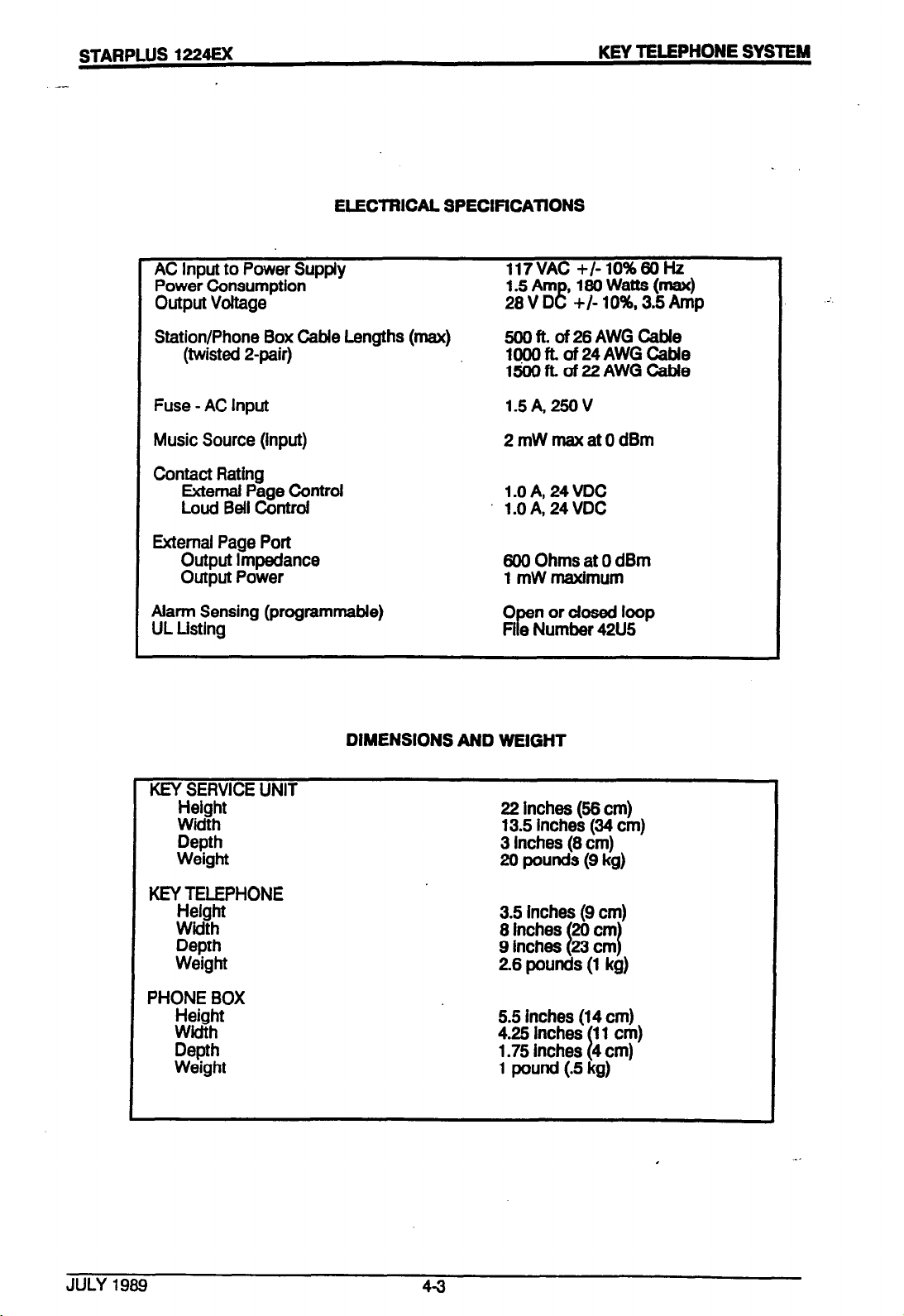
ELECTRICAL SPEClFiCATlONS
AC Input to Power Supply
Power Consumption
output voltage
Station/Phone Box Cable Lengths (max)
(twisted 2pair)
Fuse - AC Input
Music Source (input)
Contact Rating
External Page Control
Loud Bell Controi
External Page Port
Output Impedance
Output Power
Alarm Sensing (programmable)
UL Listing
DIMENSIONS AND WEIGHT
117VAC +/- lo%66 Hz
1.5Am ,186Watts(max)
28
V D e +I- 10%. 3.5 Amp
566ft.of26AWGCabie
1969ft.of24AWGCable
1569fLof22AWGCable
1.5A,259V
2mWmaxatOdBm
1.0 A, 24VDC
l.OA,24VDC
yrn$hx;;;Brn
0 nordosedlwp
$ Fi e Number 42U5
JULY
Height
Width
Depth
Weight
KEY TELEPHONE
Helght
Width
Depth
Weight
PHONE BOX
Height
Width
Depth
Weight
1969
4-3
22 inches (56 cm)
13.5 inches (34 cm)
3
Inches (8 cm)
20 pounds (9 kg)
5.5 inches (14 cm)
4.25
Inches
1.75 inches
I 11 cm)
4 cm)
1 pound (.5 kg)
Page 31

.,.. ‘...,;:.:..,;.” _’ 8.
,
c
.-I . ...-,. .,.,, ‘in,,.+
--STARPLUS
1224EX
DIALING SPECIFICATIONS
DTMF DIALING
Frr~y Deviation
Duration of DTMF Signal
Interdigit Time
PULSE DIALING
Pulse Dialing Rate @rogrammaMe)
Percent Break/Make (programmable)
DIALING MEMORY
System Speed Dialing
Station Speed Dialing
Last Number Red&l
Save Number Redial
KEY TELEPHONE SYSTEM
+/- 1 Hz
:: msec.
i
00 msec minimum
100 msec minimum
i0 or20 pps
60/40 or 66/33
So numbers (16 digit)
20 numbers/station
(16 digit)
1 number/station
1 num(KZi!xl
(32 digit)
co Type
ENWRONMENTAL SPECIF:CAllONS
Operating Temperature
Recommended Temperature
Humidity
Heat Dissipation
I
toop start
32-104’ F (04O;C
70-78 F (21-25 C
540% (non condensing)
620 BTUs
. . I
RS232C PORT (optional)
Data Format
8 bits, 2 stop bits. no parity
SMDR
Standard format
294aracter format
60 characters, single-line printout
29 characters, 34ne printout
JULY 1989 4-4
Page 32

STARPLUS 1224EX
KEY TELEPHONE SYSTEM
w LINE
THAU
CO LINE
Pl
1
.
f
Co LINE
CO LINE
MUSIC ON HOLD
EXTERNAL PAGE 1
CONTROL CONTACT 4
es--
---_
J3
---_
-m-w
----
----
----
---_
-m-v
----
-e-v
----
---_
----
---_
==L=
----
----
----
---_
----
----
----
----
----
----
====
----
----
----
====
==,-
I
-1
--
POWER FAILURE TFtANSFhi
m
Pl
11111111111111 lllllll lllllll llllll
3
ITI
STARPLUS
1224Ex
STATION 21
1
Jl
---==--
--==
----
----
----
== ==
--
==--
---
---z
----
----
--
==
--==
====
a---
----
---====
====
--
==--
----
----
----
----
----
----
----
All External Connections ,
Figure Al
W/SURGE PROTECTOR
fi
AC CONNECTION
BATTERY INPUT
1
JULY 1989 4-5
Page 33

-
_ .‘, .,_.. .I, ,.
STARPLUS
.--
RJllC
CONNECTORS
FOR CO LINE
CONNECTIONS
POWER FAILURE
TRANSFER
1224EX
I--;
KEY TELEPHONE SYSTEM
PI
8 BGM
ADJ.
’ MOH
0 ADJ.
MDF
BATTERY BACK-UP
CONNECTOR
AC WWER’
CORD
JULY 1989
KSU - left side
Figure 4.2
4-6
Page 34

Page 35

‘. .
:
, ._, .A. _....
. .*..a....:
STARPLUS
1224EX
500 lNST’ALlATlON
500.1 SITE PLANNING
The STARPLUS
System, like most electronic office equipment,
should not be subjected to harsh environmental
conditions. To assure easy servicing and relhble
operation, several factors must be considered
when planning the system installation. Always
consider the following BEFORE installing the KSU
and wiring:
A. The KSU is designed for wall mounting only.
B. The internal power supply operates with 117
VAC, 66 Hz, single phase electricity. A 3-wire
(parallel blade with ground) receptacle must be
provided on a dedicated, separately fused 15
AMP circuit.
C. Location(s) of tdephone conduits or cable
runs.
D. The KSU should be within 25’ of the
telephone company FlJ21 X. The KSU should be
centrally located and assurances should be
made to stay within prescribed cable lengths.
500’ 26
.
i 1000’ 24 AWG twisted pair
1500’ 22 AWG twisted pair
.
E. A well ventilated area having a recommended
temperature range of 70-76 degrees F and a
humidity range of 5-86% (non condensing).
F. Lighting and accessibility of KSU for servic-
ing.
G. Protection from flooding, flammable
materials, excessive dust and vibration.
H. Proximity of radio transmitting equipment,
arc-welding devices, copying machines and
other electrical equipment that are capable of
generating electrical interferences.
I. Access to a good earth ground such as a
metallic COLD water pipe. Inspect the pipe for
non-metallic joints.
1224EX
Electronic Key Telephone
AWG twisted pair
KEY TELEPHONE SYSTEM
500.2 UNPACKING THE KSU
Remove the KSU from the shipping carton and
place it on a level working surface, face up. Inspect the KSU for physical damage.
500.3 KSU GROUNDING
TG
ensure that the system will operate properly,
a good earth ground is recommended. A metallic COLD water pipe will usually provide a rell-
able ground path. Carefully check that the pipe
does not contain insulated joints that could isclate the ground. In the absence of the cold
water pipe, a ground rod or other source may
be used. A No. 8 AWG copper wire should be
used between the ground source and the KSU.
THE GROUND WIRE SHOULD BE KEPT AS
SHORT AS POSSIBLE AND SHOULD BE CONNECTED TO THE GROUND LUG LOCATED ON
THE EOITOM OF THE KSU.
50th KSU INSTALLATION
A. The KSU is designed for wall mounting
only It should not be mounted directly on a
masonry surface.
If the KSU is to be mounted on a masonry surface. a wooden backboard of sufficient size
siiol;fd be attached to the
rot nted on the backboard.
B. E lount the KSU on the backboard using 4
kxr
>ers. (The fasteners should be selected
,:::rerully so as to be capable of supporting
:he h3l.f). Refer to Figure 5.1 for KSU dimen-
ffons
C. install the ground using an insulated 8
AWG =opper wire.
c:rounrl lug on the KSU cabinet and the other
erd to a good earth ground. See Figure 4.2.
D. The KSU power supply is located within
the KSU and all electrical connections are
provided externally. The AC power cord exits
tt. z KSU on the bottom.
AI .:I on the bottom is a fuse holder that con-
ta 3 a 1.5 Amp slow-bfow fuse.
wall
and the KSU
Attach one end to the
P:, dar for the system is distributed internally.
Page 36

STARPLUS 1224=
KEY TELEPHONE SYSTEM
E. The AC power cord should not be used with
a 3-wire-to-2wire plug adapter. Do not use extension cords. A power line surge protector
should be used to protect the power supply from
electrical surges. The surge protector should
be installed in accordance with the
manufacturer’s instructions and applicable
electrical codes.
WAFiNING: DO NOT PLUG IN THE POWER CORD
AT THIS TIME.
500.5 KSU CABLING
Four amphenol type connectors are provided on
the left side of the KSU. The male connector called
P-i
is for the
the KSU are 3 female connectors labeled J-l, J-2
and J-3. These connectors require male ended
plug cables for proper attachment.
When connecting cable tails to the KSU, make sure
the designation on the AMP hood matches the
designation at the connectors input on the KSU.
After plugging in the required cabies, a “horse
shoe” fastener should be placed around the mated
AMP connectors to secure the cable to the KSU
connector provided.
Verify that the wires are properly cross-connected.
Observe telephone standard wiring color codes
wherever necessary. See Figure 5.2.
Cabling should be routed to avoid fluorescent light
fixtures, electric motors and generators, welding
equipment and radio transmitters. Afso, care
should be taken to avoid hot locations such as
steam pipes and furnaces, and areas where wiring
is subject to abrasion.
It is NOT recommended that AC power be applied
to the system during the cable termination
process.
12
CO lines. Also on the left side of
CAUllON
be taken to ensure that not more than one set
of protectors be installed on central offfce lines
at installation premises. Improper installation of
line protectlon can present a serious safety
hazard.
566.7 KEY TELEPHONE INSTALlATION
A maximum of 24 key telephones may be installed with the 1224 key system. Each key
telephone requires 2 pair (4 wires) for proper
wiring. It is required that 3 pair twisted cabie be
used to connect the telephones to thesystem
on a 8’home run” basis. The teiephone end of
the cable should be terminated on a modular
jack. At the MDF end of the home run, the cable
should be terminated on a separate station connecting Mock (S6Ml-50) for cross connection
to.the “J” cables. This method of cabling will
allow for easy isolation of station equipment
during trouble shooting procedures.
500.8 WALL MOUNT KIT INSTALlA-
TION
All connections to the key telephones are fully
modular. To wall mount the key telephone, it is
necessary to have one Wall Mount Kit and one
630-A type modular wall mount jack assembiy
equipped with 2 mounting lugs.
A. Remove the mounting cord from the
telephone. This cord will no longer be
needed but should be retained for main-
tenance purposes.
B. Substitute the short modular cord on the
wail mount baseplate for the mounting cord
removed in A.
C. Rotate the plastic number retainer upwards to expose the screw underneath.
Remove the screw and slide the cover plate
under the number retainer towards the hook
switch.
500.6 LIGHTNING PROTECTION
The 1224 should have central office lines protected
with proper lightning surge arrestors. The central
office lines are exposed to damaging surges induced by direct or non-direct lightning strikes. The
protection should contain a complement of 3-eiement gas discharge tubes which ground high
potential surges and associated circuits to absorb
and filter lower-level surge potentials. Care should
D. Replace the cover piate with the handset
retainer tab that is mounted in the wall mount
baseplate and secure with the screw from C
above.
E. Rotate the plastic number retainer
downward and snap into place.
F. Align the mounting tab on the outer edges
d the wall mount + with the hdes on the
key telephone base. Snap shut and fasten
with the screw.
Page 37

\..,. r~..:!~-r..,‘.... ..- . . . -,
‘,,.. . *
STARPLUS 1224EX
_
G. The telephone can now be mounted to the
wail by matching the 2 keyhole slots on the
baseplate with the lugs on the modular cover assembiy. Check to make sure that the modular
connector on the baseplate is firmly connected
to the wall jack.
500.9 PHONE BOX INSTALLATION
The
1224
Phone Box can make calls to preassigned stations as well as receive intercom calls.
The unit should be located in weather protected
areas where paging or monitoring is required.
The Phone Box consists of a top housing and bottom mounting plate.
speaker microphone, wire terminals and electronic
circuitry. The housings are separated by inserting
a thin, flat-edged tool at the bottom rim of the assembly. By pressing inward on the recessed
retaining tab, the assembly will open.
The connection of the Phone Box@) to the KSU
is identical to that of the key telephone.
Section 500.7.
The bottom plate of the Phone Boxassembly isfas-
tened to the wail by mounting with customer sup
plied No. 8 or larger pan head screws. The cable
is routed through the cable-entry hdes provided
on the bottom plate and is connected to the screw
terminal strip on the upper housing. Four screw
terminals are Identified by wire color on the
silkscreened printed circuit board to correspond
with the wiring sequence at the punchdown con-
nector at the MDF.
The top housing has a
Refer to
KEY TELEPHONE SYSTEM
Em1 1 EXTERNAL MUSIC SOURCE
Music-on-hold as well as Background -music
can be connected using a customer provided
,nusic source. Separate Music-On-Hdd and
background music volume adjustments are
provkfd on the KSU. (Figure 4.2).
Background music (BGM) levels are also adjus-
table at each key telephone set. Connections
are made on the J-8 connector, the MOH pair.
See Table 5-8.
500.12 ALARM INSTALLATION
An alarm signal can be transmitted to each station (except phone boxes) in the system. When
activated by an external alarm system, a continuous or repeated tone is transmitted to the
&tron speakers. Leads from the external alarm
are cxmctad to the J-3 terminals ALMT and
ALMB ,.,Figure 5.5). See Section 600 for
programming alarm states. After the alarm has
sounded, rhe system must be reset by first clearing the a&m condition on the extemai system
and [hen lifting the handset an any station
programnied to receive alarm and dialing ‘9”.
500.13 EXTERNAL PAGING
An amplifier for external paging can be connected to the 1224 key telephone system. Any
teiephone in the system can access this paging
equipment by using a dial code. There is one
External Paging Zone (without amplifier)
provided in the 1224 system.
The slack wiring should be pulled back through the
bottom mounting plate and the top housing
snapped shut. Refer to Section 600.6 (statlon
class of service) to program phone boxes.
WARNING: Make connection at the phone box
before punching down on the MDF.
500.10 DSS/BLF CONSOLE INSTALLATION
Each DSS/BLF requires 2 pair (4 wires) for proper
installation. Three-pair twisted cable is recommended to connect the DSS/BLF units on a “home
run” basis. Each DSS/BLF must be used together
with a key telephone, therefore a maximum of 12
units can be used in the system. Refer to the
programming instructions.
JULY
1989
53
The output impedance of the paging zone is 600
Ohms. The low level voice signal output is
specified at 5 milliwatts. Dry contact control is
provided to switch on the external amplifier
equipment or to momentarily remove background music, if externally supplied to the
paging device. All connections are made on the
J-8 punchdown connector. The voice output
from the key telephone system is provided on
the EPVT and EPVR pair. The “make” contacts
are Mentified as pair EPCTL The paging port
can be connected to a two way paging system.
Page 38

STARPLUS 1224Ex
500.14 LOUD BELL CONTROL/ALEAD INDICATION
The STARPLUS
tact closure to activate external signaling equipment during incoming CO line ringing. The station
or CO line that is to signal is selected by programming (see Section 600).
1224
system provides relay con-
KEY TELEPHONE SYSTEM
delays or improper loading. A step-by-step
checklist is provided for this purpose:
A. Make sure that the KSU is properly grounded
according to the instructions in Section 566.3.
8. inspect the MDF for shorted wiring or improper polarity that would affect the key
telephones.
There are 4 control contacts which can be assigned to any combination of stations and/or CO
lines. Locate the control contacts on the terminals
of the connecting block. Two wires are connected
to these terminals and routed to customer
provided signaling equipment. Refer to Figure 5.5.
500.15 EMERGENCY TRANSFER
in the event of a commercial AC power interruption, the first 3 CO/PBX lines will automatically
transfer to single line telephones (if installed) for
emergency communications. These SLTs should
be equipment with ringers. They can be DTMF
type instruments or rotary dial. Connection is
made on the modular G-conductor located direct-
ly above the
J-3/P-l
connectors. See Figure
5.4.
500.16 HEADSET INSTALLATlOti
The STARPLUS key telephone has been designed
to operate with industry standard modular headset
adapters and operator headsets. To modify a key
telephone to use an external headset:
A. Pius the headset adapter cord into the vacant
headset jack on the key telephone base.
B. Plug the telephone handset cord into the
headset adapter box where indicated by the
headset manufacturer’s instructions.
C. Turn to the programming section of this
manual. Enable the headset option for that particular station.
Speakerphone operation is automatically disabled
and such features as On-Hook Dialing and Handsfree speakerphone become inoperable.
However, incoming page/voice announcements,
tone ringing and background music will still be
heard over the key telephone speaker.
C. Make sure that plug-ended MDF cables to
the KSU are secure and are plugged into the
correct position.
D. Plug the AC power cord into the dedicated
117
VAC outlet.
500.18 SIU MODULE INSTALLA-
TION
A. Turn OFF the KSU power by removing the
pfug from the AC outlet.
B. Remove the Program Module from the
KSU.
C. Unscrew the 6 screws holding the KSU
cover and remove the cover.
D. Open the SIU module box and verify the
following components are included:
- 1 each SIU printed circuit board
WB)
- 1 each 16-conductor rfbbon cable
- 1 each RS232C adapter cable
E. Push the ribbon cable into the socket on
the underside (solder side) of the SIU board.
Make sure the contact “fingers” of the cable
align with the contacts of the connector.
F. Hold the SIU so that the ribbon cable is on
the right bottom side extending downwards.
Gently push the free end of the ribbon cable
into the SIU socket (CN 1) on the KSU.
G. Remove the RS232 mounting hole screws
and cover on the right hand side of the KSU.
Install the SIU into the mounting hole and
secure with the 2 screws.
H. Replace the KSU cover.
500.17 POWER-UP AND INSTALLATION CHECKLIST
Prior to actual power-up and initialization, the key
system should be checked over to avoid start up
JULY 1969 5-4
installation is now complete.
NOTE: Any RS232C compatibfe printer may
now be connected tq the RS232C port .on the
Page 39

.., ,:,., :,L.>c,, ., i.. ,
1
.
. . . ._ __,. ,__il
STARPLUS 1224EX
KSU. The baud rate is programmable in data base
programming (300 or 1266 baud).
5.1 g RCU
INSTALLATION
A. Turn OFF power to KSU by unplugging from AC
outlet.
B. Remove program
mdUk.
C. Remove screws holding the KSU cover.
Remove the cover.
0. Open the RCU box and verify the contents:
_ 1 each RCU module
- 1 each battery
_ 1 each plastic beaded tiewrap
E. Locate the battery. The end with the color
ring is negative.
Install the battery into the battery socket of the
RCU being careful to match the polarity of the
battery with the polarity of the socket.
F. Push the beaded tiewrap through the hole in
the RCU next to the battery. Pull the tiewrap
around the battery and through the cinch end to
secure the battery.
G. Refer to Figure 5.9. Locate the RCU socket
(CN-2); note the top (notched end) of the sock-
et.
H. Hold the RCU so that the battery socket end
is facing toward you (battery on the bottom of
the RCU) and away from the top of the RCU
socket.
KEY TELEPHONE SYSTEM
The BBU houses two 12 V batteries connected
in series which provide 24 V of DC power. The
3BU also contains an AC input cord which 1
provides charging power when the batteries are
not in use. Batteries are NOT included.
A 10” 14 gauge jumper wire is provided for interconnection of the two 12 V batteries. Four
auspter wires (approximately 2’3 are provided
for matching the exact battery terminal size. A
plastic tiewrap is provided for securing the bat-
tenes once installed.
Any UL recognized battery may be used wih the
BBU. The larger amp hour the battery, the
longer it will take to recharge.
:‘. GESCRIPTION
A Qw=ity
The hollowing table shows the approximate
times for a fully charged supply to reach 96%
vdtap under different load conditions.
3Zr t e r y Configuration
-‘~1:) Hour 4x8
7 ,jH
14AH
4QAH
5 Hr 21/2H 1 Hr
10 Hr 5Hr 21/2H
24 Hr 14 Hr 8 Hr
8x16 12x24
I. insert the pins on the bottom of the RCU into
the RCU socket (CN-1) being careful to align ail
of the pins with the socket. Apply pressure in
the middle of the
RCU
(not the ends) to avoid
breakage while seating the RCU Into the socket. Replace KSU cover.
RCU installation is now complete.
5.20 BAlTERY BACK-UP UNIT (BBU)
I. INTRODUCTION
The STARPLUS 1224EX can be fully supported for
complete operation during a power failure. An externally provided 24 VDC battery package (gel
type) and float charger is required. A convenient
plug for battery connection is located on the bottom of the KSU.
JULY 1989 5-5
i :!f
E: 411 electronic key systems will begin to
c : :: c;te intermittently below a certain input volta! :c?. Typically reliable operation will be mainti,r:~3to96%offullvdtage.
B. Dimensions
- 8” high, 13.5” wide, 7.75” deep
- Weight without batteries: 11 lb
f*. Ssscifications
- Output fused at 4 A, 250 V
- Current limited, constant voltage
charger
- Gel type batteries
- Charger float vdtage is 27.6 V
- Cut off voltage point is 21 V
Page 40

STARPWS 1224u<
KEY TELEPHONE SYSTEM
D. Power Requirements
_ Input: 117 VAC, 68 Hz
_ Fused at 0.5 A, 250 V
E. Environment
- Temperature: O-50 C
_ Humidity: 0.96%
Ill. INSTALLATION
A. Introduction
See Figure 5.8 for the location of the input socket.
The input socket of the key system must be a
female Mate-N-Lok type connector.
B. Installation Checklist
The following items are required to install the BBU:
- 1 BBU with wire kit (5 wires) and tlewrap
- 4 No. 12 panhead screws (if wall
mounted)
- Screwdriver
- Backboard or wail shelf if applicable
- Tighten each screw so the unit fits
snugly against the backboard. Insert
2
more screws into the bottom of the
BBU where 2 more keyhole mounting slots are located.
IV. GROUNDING
To ensure that the BBU will operate properly, a
good earth ground Is recommended. A metallic
COLD water pipe will usually provide a reliable
ground path.
Carefully check that the pipe does
not contain Insulated joints that could isolate the
ground. In the absence of the cold water pipe,
a ground rod or other source may be used. A
No. 8 AWG copper wire should be used between the ground source and the KSU.
THE GROUND WIRE SHOULD BE KEPT AS
SHORT AS POSSIBLE AND SHOULD BE CONNECTEDTOTHE GROUND LUG LOCATED ON
THE BOTTOM OF THE KSU.
V. CONNECTIONS
C. Mounting
The BBU must be located within 6’ of an AC receptacle and 2’ of the KSU. It can be placed on a wall
shelf or it can be wall mounted.
To wall mount the BBU:
- The BBU is designed to be mounted on
a backboard, either the backboard the
KSU is mounted on or one specifically
for the BBU.
. Mark for screw placement, either by
measuring (the 2 top keyhole mounting
slots are 8 3/4” on center) or by placing
the BBU against the backboard (before
installing batteries) & marking the loca-
tion of the 2 top slots.
- Partially insert 2 No. 12 panhead sheet
metal screws into the backboard.
- Suspend the BBU on these.2 screws.
The large section of the keyhole will
allow the unit to easily pass over the
screwhead.
- Slowly lower the BBU so the small sec-
tion of the keyhole is directly behind the
screwhead.
Before connecting the batteries, make sure the
BBU Is unplugged and the ON/OFF switch Is
turned off.
A. Remove the BBU cover by tumlng the
4
screw locks and lifting the cover.
B. Install the two 12 VDC batteries in the ba?-
tery compartment. Thread the plastic tiewrap
through the vent holes in the slde of the bat-
tery compartment and fasten around both
batteries. Cinch the tlewrap tlght.
C.
Connect one of the adapter wires to the
Mack lo” jumper wire.
Now install this jumper wire assembly between the NEG (-) terminal of battery 1 and
the POS (+) terminal of battery 2.
D.
Connect another adapter wire to the BBU
red battery wire.
Now connect this wire to the POS (+) ter-
minal of battery 1.
E. Connect the BBU black battery wire to the
NEG (-) terminal of battery 2.
F. Make sure the ‘key system being. con-
nected Is turned on. Then connect the BBU
Page 41

..-. ‘.. .” I-, .. ’
., ,I v ,.. .I . . . . . . .._ n,..T.
STARPLUS 1224Ex
--
DC output cabfe to the battery input of the key
system KSU.
G. Make sure the BBU power switch is in the
OFF positlon. Then plug in the AC power cord.
H. Turn the power switch on the BBU to ON.
installation of the BBU is now complete.
5.21 SMDR PRINTOUT
Station Message Detail Recording provides a
detailed record of afl outgoing and/or incoming, ali
calls or long distance only calls exceeding 30
seconds. This feature is enabled in database
programming. If enabled, information begins
recording when the call starts and terminates when
the call ends. If the call was longer than 30
seconds, the infonation is queued for printing.
The SMDR record contains the following information:
2
digits - station originating the call
2
digits - CO line used
KEYTELEPHONE SYSTEM
28 Cfumcter Format
This format is 28 character/3 line printout with
automatic carrlage return (CR) and line feed
(LF) at the end of each line.
AABRHH:MMHH:MM:SSMM/DD/YY
ccccccccccccccccccccc
EEEEEEEE
SMDR will retain a queue of the last 16 “re-
quests”. This ensures that the most recent
records are retained in the event of terminal
failure. If you are using a printer to display the
customer database, call records will continue to
print In between the display of the database.
A
header containing information on the SMDR
printout will print every 66 records. This header
will be: CO TOTAL START DATE DIALED ACCCXJNT CODE
The ft,.c Ming are sampIe printouts:
10 0lOO:Ol 08:48:55 04/25/88 :12345878
5 digits - tail duration (hours, minutes)
10 01 0O:Ol 08:51:11 04/26/88 123458:
8 digits - time of day call originated (hour,
minute, seconds)
12 02 0o:Ol 08:51:21 04/28/88 1234587890 :1234
8 digits - date call originated (month, day, year)
24
digits - telephone number dialed
8 digits - account code
10 01 CO:01 085346 04/26/88
12346678
10 01 0O:Ol 08:64:42 f&I/26/88
1234667890
80
Character Format
The standard format is an 80 character/single line
printout with automatic carriage return (CR) and
line feed (LF) to advance paper.
AABBHH:MMHH:MM:SSMMIDDMYCCCCCCCCCC:EEEEEE
12
14 02 0O:Ol 08:X42 04/26/88
1234667890123466789
12346678
AA = station placing the call
BB = CO line used
HH:MM = duration of the call
HH:MM:SS = time call started
or
MM/DD/YY = date call was placed
CC..CC = telephone number dialed
EE = account code
JULY
1989 5-7
Page 42

STARPLUS 1224EX
J-l STATION WIRING J-2 STATION WIRING
:OLAR
‘AIR
is-
KEY TELEPHONE SYSTEM
Table 51 Table 52 .
ESIG
ESCRP
‘AIR
5T
:OLOR
ESIG
ESCRP
1
2
3
4
5
6
7
8
9
10
11
12
13
14
15
16
17
18
19
20
21
22
23
24
25
26
27
28
29
30
31
6
32
33
8
34
9
35
10
36
11
37
12
38
13
39
14
40
15
41
16
42
17
43
18
44
19
2
46
21
47
22
48
23
49
24
50
25
WH/BL
1
k.iz
2
tzisz
GNMRl
3
WH/BN
4
!sT.
5
SW
RD/BL
BURO
RDIOR
7
OR/RD
RD/GN
GN/RD
RD/BN
BNFID
RDlSL
SURD
BK/BL
BUBK
BWOR
ORJBK
BK/GN
GNlBK
BK/BN
BN/BK
BWSL
SUBK
YUBL
BLML
YUOR
ORJYL
YUGN
GN/YL
YUBN
BNIYL
YUSL
SUYL
WBL
VT1
vR1
DT 1
DRl
vr2
vR2
DT2
DR2
in-3
vR3
DT3
DR3
vr4
vR4
DT4
DR4
VT5
VR6
DT5
DR5
VT6
VR6
DT6
DR6
VT7
vR7
DT7
DR7
W8!
VR8
DT8
DR8
VT9
w9
DT9
DR9
VF 10
M110
DT 10
DR 10
VT11
Ml11
Et%
OWVI
WGN
GNM
WBN
DT 11
DRll
VT 12
VR 12
DT 12
DR 12
LY
SIJV
-
-
STA 10
STAll
STA 12
STA 13
STA 14
STA15
STA 16
STA 17
STA 18
STA 19
STA20
STA 21
SPARE
.7
2
3
4
5
6
8
9
10
11
12
13
14
15
16
17
18
19
a0
21
22
23
24
25
1
26
27
2
28
3
29
4
30
5
31
6
32
1
WH/BL
BVWH
WWOR
i2.g
GNDVH
WWBN
BNMM
wH/SL
SLNVH
RD/BL
BURD
RDlOR
OWRD
i3
8
34
9
35
FUXGN
GN/AD
RD/BN
BNiRD
RDlSL
SURD
ii
11
37
12
38
13
39
14
40
15
41
16
42
17
43
18
44
19
BKAL
BUBK
BK/OR
OFL’BK
BWGN
GN/BK
BK/BN
BN18K
BK/SL
SUBK
YUBL
BLIYL
YUOR
ORNL
YUGN
GNIYL
YUBN
BNIYL
YUSL
24
46
21
47
SUYL
WBL
;Kl
22
48
23
49
24
50
25
&Ki
GNM
WBN
FE
SLM
vr 13
VR 13
DT 13
DR13
VT 14
VR 14
DT 14
DR14
VT 15
VR 15
DT 15
DR15
VT 16
VA16
DT 16
DR 16
VT 17
MI17
DT 17
DR17
VT 18
VR 18
DT18
DR 18
VT 19
VR 19
DT 19
DR 19
Ei
DT2O
DR20
VT21
vR21
DT 21
DR 21
vr22
vR22
DT22
DR22
VT23
vR23
DT23
OR23
VT24
vR24
DT 24
DR 24
-
-
STA 22
‘STA23
STA 24
STA 25
STA 26
STA27
STA28
STA 29
STA 30
STA31
STA32
STA33
SPARE
5-a
.
Page 43

‘. ,,., ,..
.i ‘.
*‘.
.
. . . 1.. ,,
L ..L.A’> :. ._,.. ,, ,~ ,...
STARPLUS
1
2
3
4
5
6
7
8
9
10
11
12
13
14
15
16
17
18
19
‘IN
26
27
2
28
3
29
4
30
5
31
6
32
7
33
8
34
9
35
10
38
11
37
12
38
13
39
14
40
15
41
16
42
17
43
18
44
19
45
20
46
21
47
22
48
23
49
24
50
25
‘AIR
20
21
22
23
24
25
1224EX
KEY TELEPHONE SYSTEM
Tadle 53 Table 5-4
J-3 MISCEUANEOUS P-l CO LINE WIRING
ExxP
MUSIC
INPUT
MT.
PAGE
PAGE
CONTACT
ALARM
INPUT
CONTROL
XmTROLl
CONTROL
xlNTRoLz
CONTROL
ZONTROLZ
CONTROL
ZONTROL4
SPARE
‘AIR
7
8
9
10
il
12
13
14
15
16
17
18
19
20
21
22
23
24
25
‘IN
28
27
2
20
3
29
4
30
5
31
6
32
7
33
8
34
9
35
10
36
11
37
12
38
13
39
14
40
15
41
18
$2
17
43
18
44
19
2
46
21
47
22
48
23
49
24
50
25
1
:OLOR
WH!BL
Zi!i
EE4
GNAW
WWBN
ml/w-i
WWSL
SW
RD/BL
BURD
RDlOR
OWRD
WGN
GN/RD
RD/BN
BN/RD
RDISL
SURD
BWBL
BUBK
BWOR
OFUBK
WGN
GN/BK
BWBN
BNJBK
BWSL
SLIBK
YUBL
BUYL
YUOR
OWYL
YUGN
GN/YL
YUBN
BNIYL
YUSL
SUM.
WBL
4%
ORM
WON
$E
BNM
WSL
SUVl
lESIG
z
T2
E
E
R4
T5
R5
it
z
z
T9
m
T10
RlO
Tll
Rll
T12
R12
SPARE
1
:OLOR
WWBL
x
tzEG
GNMRl
WWBN
BNMM
wH/SL
SlfWH
RD/BL
BURD
RD/OR
OR/RD
RDlGN
GN/RD
RD/BN
BN./RD
E%
BWBL
BUBK
BWOR
OWBK
BWGN
GN/BK
BKIBN
BN/BK
BWSL
SUBK
YUBL
BUYL
YUOR
OWYL
YUGN
GNIYL
YUBN
BNlYL
YUSL
SUYL
WBL
Xi
ORM
WGN
GNM
WBN
BNM
WSL
SLM
)ESIG
MOHT
MOHR
EPVT
EPCTL
EPCTL
CEKT
CNTLlP
CNTIJT
CM&R
CNTL3T
CNTWR
CNTL4T
CNTUR
SPARE
ExxP
co1
,co2
co3
co4
co5
cm
co7
CO8
co10
CO11
co12
SPARE
5-9
Page 44

Page 45

.,
,_.a I.’
.
.
.-1
__I ..I I_ .,.,,_ L, _.
STARPLUS
---
1224EX
GREEN
RED
BLACK
YELLOW
v-r
VR
DT
OR
!r
KEY TELEPHONE SYSTEM
GREEN
RED
BLACK
YELLOW
VT
. .
DT
DR
I
Key Tel@phone Wiring
BLK YEL RED
DSS Wiring
GRN
Key Telephone Wiring
Flgure 5.2
5-l 1
Page 46

STARPLUS 1224EX
--
a
KkY TELEPHONE SYSTEM
yb
CONNECTING
BLOCK
TELEPHONE BASE PLATE .I
MOUNTING PLATE
.
. .
/
’
Q
.
.
RATED STUDS
\
Wall Mounting the Telephone
Figure
5-12
5.3
Page 47

; _-.a :. ....... - ..
_ .
., L . .
......
STARPLUS 1224Ex
PROCESSOR OR
POWER FAILURE
STATION
1 STATlONWlRlNG 1
I
I I
I
I
TIP ! GREEN
RING RED
I
f
I
6 CONDUCTOR 1
CORD&JACK 1
A I
KEY TELEPHONE SYSTEM
KSU CIRCUITRY
-NOTE1
I
1 FROMRJ21X
I ’
I
np
CO UNE 3
Note1 : Contacts are shown in power failure mode.
Proceww or Power Failure Transfer
Flgum 5.4
CO LINE 1
Page 48

STARPLUS
1224Ex
J3 CONNECTOR
BIJW
1
--
--
MOH
MOH
KEY TELEPHONE SYSTEM
INPUT
+
I
I- -,-------J
77
WKI
27
-4
3+
WIBR
29
BR/W
4
rt
--
--
--
--
--
--
EPVT
EPVR
EPCTL
ALMT
ALMR
4J
VOICE
Input Impedance AMP
=600 Ohm @ 0 dbm
EXTERNAL
ALARM DEVICE
INPUT
rt
v----e--
L -----
---7
---- A
30
W/S
CNTLlT
--
-4
CNTLl R
--
5+
CNTL2T
31
6
NOTE: There are four ccntrd cantacts.
Extmsl Connections
--
CNTL2R
FIgtIre 5.5
5-l 4
~+=-;I<’
CUSTOMER PROVIDED DC
I
MAKE CONTROL
I
LOUD BELL
Page 49

.-
STARPLUS 1224EX
KSU
WE)
Pin #
KEY TELEPHONE SYSTEM
.
Printer/leninal
(DW
Pin #
2
3
Transmit Data
Receive Data
--.-< 2
..->3
RTS (Request to sex.
CTS (Clear to sew
DSR (Data set ready,
7
DTR (Data Terminal Res..
RS-232C PINOUT
Data Communication Requirements are
GND
.-.-<4
.-.->5
---+7
---<20
fe 4 Pm Compatible
x s II code Ccfnoatlble
- ?ata Biis and 1 Stop Bit
_: L.Parlty
RS232C Conn~ions
Figure 5.6
Page 50

STARPLUS 1224E)t
KEY TELEPHONE SYSTEM
Battery Compartment
I
Low Voltage Plug Outputs
CONNECT
li%ELcx
CONNECTOR
o”
0
‘f
e
I-
I
I
\
BBU lnstallntion
~LEDlit(ACf.XhWiSON)
1 lit
fbs am aliwgiRar
(System working on E
.-I
WUIOS)
FlQufe 5.7
5-16
Page 51

.
STARPLUS 1224EX
1224 KSU
WITH COVER
OFF
KEY
TELEPHONE SYSTEM
SIU
SOCKET
MOUNTING
SCREWS
RS232C
CONNECTOR
0 ,
7
/
-.-
:
G
n
0
RCU & SIU Installation
Figure
5.8
0
SIU
BOARD
R
0
II
S
2
3
:
m
MOUNTING
SCREWS
/
Page 52

600 CUSTOMER DATA BASE PROGRAMMING
600.1 INTRODUCTION
by pressing the asterisk (*) and entering that
program code.
The 1224 Key Telephone system can be
programmed to meet each customer’s individual
needs. All programming is done at station 10 using
the Enhanced or Executive model key telephone
as the programming
A BASIC model telephone cannot be used.
It is strongly recommended that the Executive
telephone be used to make programming easier.
When the program mode is entered, the key
telephone being used no longer operates as a
telephone but as a programming instrument with
all of the buttons redefined. The keys of the dial
pad are used to enter data fields (program codes)
associated with system, station and CO line features. CO line buttons and station buttons are
used to determine CO line access, assign class of
service, determine station features, indicate stations, line group numbers, CO line configuration,
system features, toll tables, etc.
At the time the system is installed it must be initial-
ized to load default data into memory. See Table
6-l for default data. If this pre-programming suits
the customer, initialization is all that is needed.
inStrUfTient.
When programming features, tones are
provided to help the programmer determine if a
correct or incorrect entry has been made. A
solid one second tone indicates the data was
accepted. An interrupted tone means an error
was made. When this occurs, m-enter the data
field and try again. Until new data is entered and
accepted, the system will continue to operate
under default or previously entered values.
When the hold button is pressed to enter data,
that data will be stored in a temporary buffer
area. Data is not entered into system memory
and has no effect on telephone operation until
the program mode is exited. This is done by
pressing the ON/OFF button to OFF. Then the
data in the temporary buffer is copied into per-
manent memory. It is at this point that programming affects telephone operation. Until the
programming mode has been exited, the system will operate under default or previously
programmed data.
Some features must have more than one data
field programmed for that feature to work.
Where this is the case, it will be stated in the instructions.
Any time data is to be changed, the program mode
must be entered and then the individual data field
(program code). A data field can be entered to
determine current programming or to change a
specific feature within that field.
During programming, the other key telephones in
the system operate normally. If a data field is
entered but nothing is changed, or changed but
not entered into memory (pressing HOLD), the
previous data will remain intact upon leaving that
data field. Data fields can be entered at random..
In many of the data fields, programming is sequen-
tial, i.e. upon completing the programming of one
CO line or one station, the next line or station will
automatically light up for programming.
changes are to be made in the next line or station,
simply exit the data field by either leaving the
program mode (pressing the ON/OFF button to
OFF) or entering another data field. This is done
If no
600.2 CUSTOMER DATA
WORKSHEETS
Before any attempt at programming is made, it
is strongly recommended that customer data
worksheets be prepared. These worksheets
should become part of the permanent record of
customer programming. Refer to the following
sections when preparing the worksheets.
600.3 DATA BASE FIELDS
The data fields are used to set system timers,
determine central office line features and key
telephone features. Table 6-l lists the default
values, which are pre-programmed into the system, and the data fields (program codes).
When entering CO line data and station data, be
sure to enter the exact number of digits
specified. The data fields and features are fur-
ther described in the following paragraphs.
JULY 1989 6-l
Page 53

_,,- ‘,.,‘.;,.,:J:, L !.. ,. : 0 . ’ *. -.
. . ,(
.., ,.. ., . . ‘__. . . . , ; I. ., .> . ../ ,h_.._,.
STARPLUS 1224u<
600.4 PROGRAM MODE ENTRY
Programming is always done at station port 01
using either the Enhanced or Executive key
telephone. The Basic Telephone cannot be used
for programming.
this station regardless of the class of service or intercom number assigned to this station or which
station has been assigned as the attendant.
To enter the program mode, the programmer must
first verify that the key telephone is properly con-
nected to station port 01.
STEP 1
Press ON/OFF button to ON (button lights & in-
tercom dial tone is heard).
STEP 2
On the dial pad, press the asterisk (*) twice.
STEP 3
On the dial pad, enter 56-23 (LOAD). Confirmation tone is heard. Dial tone is removed.
STEP 4
The HOLD button & the ON/OFF button will be
lit.
The system is ready to program (other key
telephones connected to the system continue to
operate normally).
l
* initialize here if necessary.
STEP 5
Press the asterisk (*) once.
STEP 6
Dial the 2 digit program code for the desired data
field.
STEP 7
Enter customer data.
Programming is always done at
KEY TELEPHONE SYSTEM
TO exit the program mode, press the ON/OFF
button (light will extinguish). All new data now
beccme effective and operational.
600.5
INITIALIZATION
.
The svstem has been pre-programmed with certain eatures which are called default data.
These features are loaded into memory when
ths system is initialized. The system should be
i~;Gakzed when installed or at any time the data
b x9 r:as been corrupted.
PG ~nitiaiize the system to default values:’
%rer the programming mode.
@fer to steps 14, Sec. 696.4).
i;TEf
2
?r,;ss the asterisk (*) once.
mzP 3
3r the d&l pad, enter the numbers 4-6-4-6
(iPIT).
c'TZ!: 4
Pr:xs
the HOLD button.
Confirmation tone is heard.
:Wa-lit data is now loaded.
70 dafatul only certain parts of the database,
: ‘.:e tr:e following program codes instead of the
‘%x i&ion code.
I..
+4
i will inltiiize toll tables only.
2:: will inltlallze system data only.
“1 i; will initialize CO line,data only.
‘OZ will initllize station data only.
‘31i will initialize flexible button programming
my.
STEP 6
To load the entered data, press the HOLD button. A burst of one second confirmation tone
should be heard.. If an interrupted (error) tone
is heard, reenter the data starting with step 5.
STEP 9
Repeat from step 5 until all data has been stored.
JULY 1969
6-2
Page 54

STARPLUS 1224u<
600.6 STATION CLASS OF SERVICE
KEY TELEPHONE SYSTEM
PROGRAMMING STEPS
Make sure you have entered the programming
mode (Sec. 600.4).
If you wish to change the class of service
.
of a station, dial an (*) asterisk & 01 on the
dial pad.
. Press the button of the station to be as-
signed a class of service. If the station is
22-33, press STATION RANGE button
first.
Then press appropriate button for the
.
class of service being assigned to that station - see beiow. Bydefault all stations are
assigned Class of Service 1 (unrestricted).
. Press HOLD to enter data.
The next station button will light for programming.
DESCRlPTlON
Each station must be assigned a class of ser-
vice which determines the type of calls a station
may make. There are 2 Toll Restriction tables
labeled A and B in which you may enter long distance numbers to be allowed or denied (Refer
to Section 606.31).
Class 1 =unrestricted
Class 2 = governed by Table A
Class 3 = governed by Table B
Class 4 = 7 digits maximum, no “0” or “1” can
be dlaled as the first digit
. Class 5 =intercom & paging only
Class 6 = receive only/no disling
When a CO line is marked PB)(I COS restrictions
apply to the station on& if one of 4 codes are
dialed first (see sec. 600.22).
Stationsmustbeprogrammed toreceivephone
boxlalarm signaling (see sec. 600.7) and must
also be programmed with the corresponding
station button of the phone box (set 600.9).
NOTE: When the STATION RANGE button is lit, the
station indicated is in the upper range (22-33). For
example, station button 16/26 is iii - if the STATION
RANGE button is lit, station 26 is being programmed;
if STATION RANGE button is not lit, station 16 is
being programmed.
JULY
1989
6-3
Page 55

STARPLUS
-.--
1224EX
KEY TELEPHONE SYSTEM.
600.7 SW4TlON PROGRAMMING
PROGf3AMMlNG STEPS
If you are in the programming mode, continue
using the program codes. If you are starting to
program here, enter the program mode first (Sec.
600.4).
if station features are to be changed, dial
.
an asterisk (*) and 02 on the dial pad.
. Press the button of the station to be
programmed. If stations 22-33 are being
programmed, press STATION RANGE
button first (LED will light).
.
Then toggle on or off the following
program buttons depending on what features that station is to be given.
. If the LED is lit, that feature is enabled; if
not lit, that feature is denied to that station.
. Press HOLD to enter.
DESCRIPTION
Station features are described as follows:
Do Not Disturb (DND)
A yes entry (LED on) indicates this station is allowed the Do Not Disturb feature. The
programmed Attendant cannot have DND. Allowed by default.
Speed Dial (System)
A yes entry (LED on) indicates this station is al-
lowed access to system speed dial numbers.
Default allows system speed. The last 20 numbers (bins 30-49) are not monitored by toll
restriction. Refer to toll restriction tables, sec-
tion 600.31, and programming system speed
numbers, section 600.37.
Alarm/Door Signal
Stations can be designated to receive alarm sig-
nals through the telephone speaker. These sta-
tions will also receive alert tone from a phone
box. Default gives no stations this feature (LED
off). NOTE: A STATION BUTTON MUST BE
ASSIGNED TO PHONES RECEIVING PHONE
BOX RINGING (Section 690.9).
Refer also to section 600.19 to enable alarm signaling and to program alarm detection & signaling.
Preferred tine Answer
Stations can be given the ability to answer in-
coming outside line calls, transferred & recalling lines and line queues by simply going
off-hook.
Disabled by default (LED off).
Call Forward (Station)
Stations can be allowed or denied the ability to
have incoming, intercom and transferred outside lines fowarded to another station. This
feature is allowed by default (LED on).
Auto Select
This feature allows a user,to press an idle CO
line button and have that line automatically
seized and dial tone received through the
speaker. The user can then dial manually or w
JULY
1969 6-4
Page 56

STARPLUS 1224EX
PROGFIAMMING STEPS
KEY TELEPHONE SYSTEM
To program further station features, d&l
0
an asterisk (*) and 03 on the dial pad.
. Press the button of the station to be
programmed. If station 22-33 are being
programmed, press STATION RANGE
button first.
Then toggle on or off the following
.
program buttons depending on what fea-
tures that station is to be given.
. Press HOLD to enter.
The next station button will light for programming.
select a station or speed number. Refer to Sec-
tion 666.9, flexible button programming.
Allowed by default (LED on).
Headset
This feature disables the speakerphone and
must be enabled if the telephone is to be
equipped with a headset.
Disabled by default (LED off).
Page Access
Stations can be denied the ability to make page
announcements. If a station is to be denied
paging access, do not use Class of Service 6 to
accomplish this.
Allowed by default (LED on).
NOTE: lf the STATION RANGE button is lit, it means
that the station indicated is in the upper range (2%
33). For example, station button W26 is lit - if the
STATION RANGE button is lit, station 28 is being
programmed; if STATION RANGE button is not lit, sta-
tion 16 is being programmed.
Page 57

. . .
-.. . . .
STARPLUS 1224EX
600.8 FLDClBLE STATiON NUMBERS
PROGRAMMING STEPS
If you are in the programming mode, continue
using the program codes. If you are starting to
program here, enter the program mode first.
If station intercom numbers are to be
.
changed, dial an asterisk (*) and 04 on the
dial pad.
If you have a display phone, you will see the foliowing display:
FLEXIBLE STATION ASSIGN
PORT 01 = STA 10
I
KEY TELEPHONE SYSTEM
DESCRIPTION
By dsiault station 1 is assigned intercom number - 3, station 2 is asslgned intercom number
11, etc.
This feature allows one person to move from
one stxtion to another without changing phones
and yet take all their lndivldual station data inCiuding Intercom number with them.
However, station port 01 always remains the
programming port regardless of the intercom
number assigned to it.
The system does not allow duplicate or unassigned numbers. If this happens, error tone will
be heard when entering the data.
. Press the button of the station whose in-
tercom number is to be changed (LED will
flash). If the station number Is between 22
and 33, press STATION RANGE button
flrst.
. Press the button of the statjon number it is
to be changed to. You will hear confirmation tone and the LED will be lit solid.
. When all changes have been made, press
HOLD button.
Display will now update.
FLEXlBLE STATION ASSIGN
PORT 01 = STA 16
I
For WarnpIe, if a station with an intercom number of 16 is moved to where station intercom
numbt:r 10 was; then station intercom number
10 must be moved somewhere. 10 could be
moveo to where 23 was and 23 moved to where
16 was. This way all circuits have a unique intercom number.
NOTE: The entire system must be idle before
changes made in station numbers will take ef-
fect.
I
JULY 1969
6-6
Page 58

STARPLUS
-._--_
1224EX
KEY TELEPHONE SYSTEM
600.9 FLEXIBLE BlJlTONS
PROGRAMMING STEPS
if you are in the programming mode, continue
using program codes. If you are starting to
program here, enter the program mode first.
To program your flexible buttons, diai an
.
asterisk (*) and 05 on the diai pad.
if you have a display phone, you will see the foiiowing display:
FLEX BLITTON ASSIGN
ENTER STA #, PRESS HOLD
. Dial the 2 digit station number (1033).
. Press any button which you want to
change. See the foilowing program but-
tons:
DESCRIPTION .
Each flexible button may be given a general assignment such as multi function button, station
button, CO line button, loop key or pool key.
Multi function buttons are programmed by each
individual user to be a DSS (station) button,
speed dial button, page button or mute button.
When programming a button as a CO line button, the line number must also be specified.
When programming a pooi button, the line
group number must also be entered.
By defauit, flexible buttons are assigned as follows:
BASIC Telephone
- Buttons i-5 = CO lines l-5
- Button 6 = loop button
ENHANCED/EXECUTIVE Telephone
- Buttons l-14 = stations lo-24
- Buttons 15-16 = CO lines 7-6
- Buttons 17-22 = CO lines l-6
NOTE: You cannot program the buttons of a
keyset that is in use. When attempting to
program a keyset in use, ail LED’s will light to in-
dicate no programming will be accepted.
JULY 1969
6-7
NOTE: A multi function button can be
programmed in the system data base as a station button. After entering a “l”, enter the sta-
tion number desired, and press HOLD. The
station user can erase this programming.
When programming a button as a CO line but-
ton, refer to CO line ringing (Sec. 500.15). By
default station 10 will ring on a line.
if station 10 is not given button access to a line,
another station must be programmed to ring on
that line.
However,
Page 59

STARPLUS
1224EX
KEY TELEPHONE SYSlEM
PROGRAMMING STEPS
You will see a display like the following:
. D&l the desired code to assign button
function.
- 1 = multi (user programmable)*
- 2XX = CO line (XX is a 2 digit line number)
- 3
= loop
- 4x
= pooled group (X is a 1 digit line
group number)
. Press HOLD button. Confirmation tone is
heard.
The next sequential button will light for program-
ming or press the next button to be programmed.
Display will now update such as in the following ex-
amples:
DESCRIPTION
When programming a button as a poolecJ group
button, refer to CO line group programmjng.
Pooled group numbers match CO line group
numbers
All stations should be given a loop button so
they can receive a transferred call on a line for
which they have no button access.
A DSS button MUST be assigned to stations
receiving phone box ringing.
Continue programming buttons until the station is
completed, then go back, redial the program code,
and dial the next station number to program that
station’s buttons.
NOTE: To program the flexible buttons on a Basic
Telephone, refer to section 600.12.
JULY
1989 6-a
Page 60

STARPLUS
1224EX
KEY TELEPHONE SYSTEM
600.10 PAGE GROUPS
PROGRAMMING STEPS
If you are in the programming mode, continue
using the program codes. If you are starting
programming here, enter the program mode first.
.
If page groups are to be changed, dial an
asterisk (*) and 06 on the dial pad.
. Press the station button of the station to
be changed. Press STATION RANGE but-
ton first for station 22-33 (LED will light).
. Toggle on or off the program button for the
desired page group. See below.
- LED lit = enabled
- LED unlit = disabled
Press HOLD to enter.
.
DESCRIPTION .
Each station can be assigned to page groups
for the purpose of receiving page an-
nouncements.
There are 2 page groups. Stations can be assigned to either one or both of the groups or not
be assigned to a groupat all and thereby receive
no pages.
Stations not assigned to a page group can still
make page announcements if allowed in station
programming (Sec. 666.7). Stations can be assigned to a page group but not allowed to make
pages (see Station programming, Sec. 660.7).
NOTE: If the STATION RANGE button is lit, it means
that the station indicated is in the upper range (a-
33). For example, station button W/28 is lit-if the
STATION RANGE button
programmed; if STATION RANGE button is not lit, sta-
tion 16 is being programmf3d.
IS
lit, station 28 is being
JULY 1969 6-9
Page 61

STARPLUS 1224EX
.--
KEY TELEPHONE SYSTEM
600.11 PICKUP GROUPS
PROGFIAMMING STEPS
If you are in the programming mode, continue
using the program codes. If you are starting
programming here, enter the program mode first.
. If pickup groups are to be changed, dial
an asterisk (*) and 07 on the dial pad.
. Press the station button of the station to
be changed. Press STATION RANGE but-
ton first for stations 22-33.
e Toggle on or off the program button for the
desired pickup group. See below.
- LED lit = enabled
LED unlit = disabled
-
. Press HOLD to enter.
DESCRIPTION
Each station can be assigned to pickup groups
in order to pick up tone ringing calls at another
station in the same group. Incoming CO line
calls are excluded.
There are 2 pickup groups.
signed to either one or both of the groups or not
be assigned to a group at all and be unable to
pickup calls ringing at other stations or have
calls picked up from their station.
By default all stations are assigned to group I.
Stations can be as-
JULY
1989
6-10
Page 62

STARPLUS 1224=
--
600.12 PROGRAMMING BASIC TELEPHONES
KEY TELEPHONE SYSTEM
PROGRAMMING STEPS
If you are in the programming mode, continue
using the program codes. If you are starting to
program here, enter the program mode first.
Dial an asterisk (*) and 08 on the diai pad.
Press the station button of the station
being assigned a Basic telephone.
Press the program button indicated
below.
Press HOLD to enter.
To assign DSEVBLF press station button of
station port the DSS console is wired on.
Press program button indicated below.
Press station button of the phone the DSS
will operate with.
Press HOLD.
DESCRIPTION .
If a Basic telephone is to operate properly, it is
necessary to program which stations have this
telephone.
The following are the flexible buttons on a Basic
Telephone: refer to section 690.9 for program-
ming flexible buttons. Refer to flexible button
programming to determine the function of these
buttons.
All station ports will be assigned as key
telephones upon system initialization. The
DSS/BLF provides direct access and visual in-
.dication of all station on the 1224. See Figure
XX for button mapping.
A DSSBLP can be assigned to any port and
designated to work with any key telephone on
the 1224 system.
To remove a
station button of the port programmed as the
DSS, then press button 2. Then press the button of the DSS port again and press HOLD. The
display will now show N/A.
DSS/BLF
assignment, press the
JULY 1989
6-11
Page 63

. .
.,
STARPLUS 1224EX
600.13 CO LINE GROUPS
PROGRAMMING STEPS
If you are in the programming mode, continue
using
the program codes. if you are starting to
program here, enter the program mode first.
To assign CO line groups, dial an asterisk
l
(*) and 11 on the dial pad.
. Press the CO line as indicated in the
program buttons below. For CO line
groups 7 and 8, press GROUP RANGE
button first.
Then press the button for the CO line
.
group into which that CO line is to be
placed.
KEY TELEPHONE SYSTEM
DESCRIPTION
Eight line groups are available for CO line as-
signment. Groups should be assigned accord-
ing to type (local, FX, WATS, etc.).
All lines are placed in line group 1 by default.
Une grouping atX9cts queuing; if you qtieue on
a line, any line in that same group may be made
available to you.
tine groups are used primarily for flexible buttons assigned as pooled group buttons (Section 600.9).
. Press HOLD to enter.
Continue programming CO lines until they have all
been piaced in a group.
JULY 1989
6-12
Page 64

600.14
CO UNE DATA
DESCRlPTlON .
if you are in the programming mode, continue
using program codes. if you are starting to
program here, enter the program mode first.
if any CO line features are to be changed,
.
dial an asterisk (*) and 12 on the dial pad.
. Press the CO line button of the line to be
programmed.
. Toggle the program buttons on or off so
the LED’s light up or extinguish.
. Press HOLD to enter data.
Llne Type (CO/PM)
Each individual outside line can be
programmed to be either a CO line or a PBX line.
By default ail are CO lines (LED on).
When programming line type, refer a/so to CO
line group programming (sec. 600.13); flexible
button programming (set 600.9), CO line ringing (sec. 609.15), flash timer (sec. 606.16), and
recall timers (sec. 600.20). When marked PBX
a one or two dfgit dial code may be entered after
which to/i restriction is applied. Sec. 6.23.
.Signaling (DTMF/Pulse)
Each individuai line can also be programmed as
either DTMF (tone) or dial pulse. By default ail
are set for DTMF (LED on).
When a line is assigned as dial pulse, you can
program the breaklmake ratio and dial speed
(sec. 800.78). Refer also to the ring defect timer
(sec. 800.17).
Toll Override
An outside line may be marked for Toil Override
which allows even restricted stations to dial on
this line. By default no lines are marked for toil
override (LED off).
JULY 1969
6-13
This feature allows you to give a station a
restrictive COS and also give them a line they
can make long distance calls over. This feature
also affects system speed dial by allowing certain speed numbers to be programmed on a
specific line.
Private tine
A line can be marked as a private line. A private
line cannot be picked up with Universal Night
Answer and will not preset cati forward.
The same station can have other CO (outside)
lines that are not marked private which can be
programmed to preset forward.
A private line is created by programming
flexible burton assignments so that the b&ate
line appears at one station on/y.
To restrict
Page 65

STARPLUS 1224EX
KEY TELEPHONE SYSTEM
other stations from accessing the private line,
consideration must also be given to Pool button & CO line group assignments. Assign the
private line to a separate CO line Group. See
flexible button programming (sec. 600.9).
By default no lines are marked as private lines
(ED off).
600.15 CO LINE RINGING
PROGRAMMING STEPS
If you are in the programming mode, continue
using the program codes. If you are starting to
program here, enter the program mode first.
Dial an asterisk (*) and 13 on the dial pad
.
for day ringing stations (14 for night ring-
ing stations).
. Press outside line that is to be
programmed.
. Then press station buttons for stations
that are to ring on that line (each button
will light).
. When all stations have been entered,
press HOLD to enter data.
DESCRIPTION
Telephones can be assigned to receive incom-
ing outside line ringing during the day and/or
during the night.
Telephones that ring during the day do not
automatically ring at night. They require night
ringing programming.
Any number of phones can be assigned to ring
during the day and/or during the night.
By default, all lines ring at station 10 in both day
& night mode.
Program Code 14 operates the same as
Program Code 13 and is used to assign night
ringing stations.
To display which stations have been
programmed, press STATION RANGE button 2
times to scroll through all stations.
At least one station should be programmed to
ring on a line. See Flexible Button Progmm-
ming, Sec. 600.9. Make sure that any station
programmed for Loud Bell Control is assigned
ringing for that line.
JULY 1969
6-14
NOTE: If the STATION RANGE button is lit, it means
that the station indicated is in the
33). For example, station button M/26 is lit - if the
STATION RANGE button is lit, station 28 is being
programmed; if STATION FLANGE button is not lit, station 16 is being programmed. The same is true for
CO LINE RANGE.
upper
range (22-
Page 66

STARPLUS 1224E.x
600.16 FLASH TIMER
PROGRAMMING STEPS
lf you are in the programming mode, continue
using the program codes. if you are starting to
program here, enter the program mode first.
. If the flash timer is to be changed, dial an
asterisk (*) and 15 on the dial pad.
If you have a display phone, you will see:
FLASH TIMER
2.0
SECONDS
Press the CO line which is to be
.
programmed (see following program but-
tons).
KEY TELEPHONE SYSTEM
.
DESCRIPTION
Flash is a programmable opening on a llne for
signaling. When using an outside line, flash al-
lows a user to obtain new dial tone without
losing the line. This is patticulatiy useful behind
a PBX. (See Sec. 699.14, Une Type).
Default value for all lines is 2.0 seconds.
Each CO line Is indiviiually programmed for a
flash time. The flash timer is programmed on a
per line basis.
. Enter the 2 digit timer value on the dial pad
(0199) which corresponds to 0.1 to 9.9
seconds.
. Press HOLD to enter the data.
JULY 1969
6-15
Page 67

. .
STARPLUS 1224EX
^--
600.17 CO RING DETECT
PROGRAMMING STEPS
If you are in the programming mode, continue
using the program codes. if you are starting to
program here, enter the program mode first.
If CO Ring Detect timing is to be changed,
.
dial an asterisk (*) and 16 on the d&i pad.
If you have a display phone, you will see:
. Press CO line button for which timer will
work.
KEY TELEPHONE SYSTEM
DESCRIPTION
The duration of the ringing signal from the CO
or PBX is matched with ringing detection circuftry in the KSU. The ring detect can range
from 260 - 966 miliseconds divided into 100
msec. increments.
When programming CO ring detect, refer to CO
line signaling
programming (Sec. 600.15).
Default value for each line is 300 msec. Ring
detect time is programmed on a per CO line
(Sec.
600.14) and CO line r;nging
.
Enter 1 digit timer value (2-9).
- 2 = 200 msec, etc.
. Press HOLD to enter data.
Continue entering timer values for CO lines which
require them.
Page 68

600.18 DIAL PULSE
PROGRAMMING STEPS
.
DESCRIPTION
If pulses per second (pps) and
.
break/make ratios need to be changed,
press the (*) & dial 17 on the dial pad.
.
Press CO line button for line which is to be
assigned dial pulse. Then press the appropriate program button.
. Press HOLD to enter data.
The next outside line button will light for program-
ming.
Each CO (outside) line can send dial pulse signals to the receiving central office. The
break/make ratio and pulses per second are
programmable.
Default is 10 pps and 60/40 break/make ratio.
This program code is only used whei an ourside (CO) line has been programmed for dial
pulse (Sec. 600.14).
Default assigns all CO lines as DTMF.
When used in Canada, DOC regulations do
‘NOT allow dial pulse signaling spead to excead 11 pps with a minimum of 33 msec.
make interval and 54-68 msac. break intenM.
The requirements are mat when the system database is initialized.
.
Page 69

STARPLUS
a
1224EX
KEY TELEPHONE SYSTEM
600.19 SYsl’IEM DATA
PROGRAMMING STEPS
If you are in the programming mode, continue
using the program codes. If you are starting to
program here, enter the program mode first.
. To change any system data, dial an
asterisk (*) and 21 on the dial pad.
. Toggle the program buttons on or off so
the LED’s light or extinguish for desired
features.
- LED on = enabled
- LED off = disabled
. Press HOLD to enter data.
DESCRIPTION
I-ins Queuing
If thh. button is lit, CO line queuing is allowed on
.T system basis. Stations queuing a line are .i
:-~Aed according to the line group requested.
3l i:eWlt queuing is allowed (LED on).
%;:-?f
to CO line group programming since
JL~C :;ing follows line groups, not individual
‘.; :;?.z. See Sec. 600.13. Afso, refer to flexible
i;:rZ<\n programming for access to individual
: ‘i&c or groups of lines. See Sec. 600.9.
_ 52 Preference
^: it3 ,:ystem can be programmed to have either
:xc: Ave hold or system hold preferred. If ex-
I:!usr!e hold is preferred, the HOLD button is
yjre~ jed once for exclusive hold and twice for
-l~~sr ?I hold when placing a call on hdd. For
syrt in hold this is reversed.
fi’~:- :o system timer programming for recall
tme for both system and exclusive hold.
TraR: :er and conference calls are always placed
on z.clusive hold. Default is system hold (LED
on).
Akrm Detection
Thi:; : ?ature determines the type of alarm signal
recta ed form an external source. If the LED is
lit, if : Jeans the system will detect a closed loop,
unlit neans the system will detect an open loop.
Defa At is closed loop (LED on).
Refer “0 station programming, alarm receive to
determine who will receive a/arm signals. Also
reier to signaling and alarm enable in this section.
Alarm Signaling
This feature determines the type of signaling
receivd by the stations. If the LED is lit, it
means a repeated tone will be given; LED unlit
means a single tone will be given. Default is
repeat4 tone (LED on).
JULY
1989
6-l 8
Page 70

STARPLUS 1224EK
KEY TELEPHONE SYSTEM
Automatic Privacy
A yes entry (LED lit) means that privacy is
automatically provided on all communications
in the system. To eliminate privacy, toggle the
button so the LED extinguishes. Privacy is
enabled by default (LED on).
If privacy is eliminated, only one other station
may join in on an existing conversation.
Alarm Enable
A yes entry (LED lit) means the system is
programmed for alarm. Stations must then be
programmed to receive the alarm signal (see
Sec. 800.18). You must also choose alarm signaling and alarm detection. This feature is dis-
abled by default (LED off).
.Background Music (BGM)
This feature must be enabled if background
music is supplied to the system. Background
music is disabled by default (LED off).
Refer to Sec. 500.10.
JULY 1989 6-19
Page 71

, 1 .A.‘. . . ..I a- ..-
, L _ ,,,.: .,,. x.. .., I.‘ , . . . .
STARPLUS 1224u(
--
600.20 TIMERS
PROGRAMMING STEPS
If you are in the program mode, continue using the
program codes. If you are starting to program
here, enter the program mode first.
Exclusive Hold Recall
To change this timer, dial an (*) asterisk
.
and 22 on the dial pad.
lf you have a display phone, you will see the following:
EXCLUSIVE HOLD RECALL
060 SECONDS
r
KEY TELEPHONE SYSTEM
DESCRIPTION
This refbcts the time before an outside line
placed on exclusive hold will recall the initiating
station. If the call is unanswered for an additional equal amount of time, it will recall the, attendant and if unanswered by the attendant will
recall all phones in the system.
Default is 060 seconds.
Dial 3 digit number between 000 and 255
seconds).
* (
timer.
. Press HOLD to enter data.
Display will now update.
System Hold Recall
To change this timer, dial an (*) and 23 on
.
the dial pad.
If you have a display phone, you will see:
An entry to 000 will disable the
This timer reflects the amount of time before an
outside line placed on system hold will recall the
initiating station. If the call is unanswered for an
additional equal amount of time, it will recall the
attenoant and if unanswered by the attendant
will recall all phones In the system.
Default is 050 seconds.
.
Dial 3 digits between 000 and 255
(seconds). 000 will disable the timer.
. Press HOLD to enter.
Display will now update.
‘_
Page 72

STARPLUS
1224EX
KEY TELEPHONE SYSTEM
PROGRAMMING STBPS
Transfer Recall
. To change this timer, dial an (*) asterisk
and
24
on the dlai pad.
If you have a display phone, you will see the following:
. Dial 3 digit number between 000 and 255
(seconds). 009 will disable the timer.
. Press HOLD to enter data.
Display will now update.
DESCRlPTlON
.
Thls timer refiects the amount of time before an
unanswered transfer is recalled to the station
that initiated it. if the call is still unanswered for
an additlonal equal amount of time, it will recall
the attendant and lf unanswered by the attendant will recall all phones in the system.
Default is 039 seconds.
Message Wait Reminder Tone
. To change this timer, dial an (*) asterisk
and 25 on the dial pad.
If you have a display phone, you wiil see thefoilowing:
MSG Reminder Tone Timer
00 MINUTES
. Dial a 2 digit entry between 90 and 99
(minutes). 00 disabies the timer.
. Press HOLD to enter.
Display will now update.
A station with a message waiting can be
reminded at a timed interval with a tone. The
tone will continue until ail messages have been
answered. The fntervai can be programmed between 90 and 99 minutes.
By default the timer is disabled.
JULY 1989 6-21
Page 73

.’ ’ - .-
. . . .._ .,...I’. . . . . . . . .,I , . .._
STARPLUS 1224EX
PROGRAMMING STEPS
Pause Timer
To change this timer, dial an (*) asterisk
.
and 26 on the d&i pad.
if you have a display phone, you will see thefdlow-
ing:
PAUSE TIMER
2 SECONDS
Dial a 1 digit entry between 1 and 9
. (seconds).
. Press HOLD to enter data.
KEY TELEPHONE SYSTEM
DESCRIPTION
When dialing a speed number, a timed pause in
digit sending can be inserted into the number.
The iangth of the pause is contrdled by the
pause timer and can be from 1 to 9 seconds.
The length of the pause is important in both system and station speed d&i numbers.
Defaua is 2 seconds.
Display will now update.
Page 74

_ , ,.. _. -_.. .---
STARPLUS 1224EX
--
600.21 EXECUTIVE/SECRETARY ASSIGNMENTS
PROGRAMMING STEPS
lf you are in the programming mode, continue
using the program codes. If you are starting to
program here, enter the program mode first.
. To program executive/secretary assign-
ments, dial an asterisk (*) and 27 on the
dial pad.
If you have a display phone, you will see:
EXECUTIVE/SECRFTARY
I I I I
. Press button for desired execu-
tiq/secretary pair assignment.
KEY TELEPHONE SYSTEM
.
DESCRIPTION
There are 4 sets of Executive/Secretary pairs
available for assignment. When the Executive
Is busy or in OND, Intercom calls and transferred
calls will be automatically routed to the
secretary.
One executive can go to 4 secretaries, 1
secretary can answer for 4 executive or 1 execu-
tfve can be assigned 1 secretary, etc. ’
*NOTE: If either station is number 22-33, press
STATION RANGE button first.
By default there are no pairs assigned.
. Press the station button to select the
desired executive station (LED lights
steady).*
.
Press the station button to select the
desired secretary station (LED flashes).*
. Press HOLD to enter.
Page 75

STARPLUS
1224EX
600.22 LOUD l33L/A4EAD
PROGRAMMING STEPS PESCRlPTlON
If you are in the programming mode, continue
using the program codes. if you are starting to
program here, enter the program mode first.
Dial an asterisk (*) and 28 on the dial pad. A Loud Bell contact can be assigned to any sta-
.
if you have a display phone, you will see:
KEY TELEPHONE SYSTEM
Four contacts are available to be assigned
either as loud bell control or as A-Lead indica-
tion.
ticns and will follow the ringing assignments of
the assigned station including tone ringing in-
ic>zogm, recalling and transferred CO lines.
/- Mead contact can be assigned to any CO
ii:
R -ember to assign ringing to any station
p;. -Trammed f
IX
5.
Also a station programmed for A-Lead
iix lion, must be given that CO line appa, x-e, Sec. 600.9.
or Loud Bell Control, Sec.
. Press the button of the contact to be
programmed.
. Press the LBC or A-Lead button to indicate
which is being programmed.
Then press station (LBC), or CO line (A-
.
Lead) button to be assigned. if the station
being assigned is in the 22-33 number
range, press STATION RANGE button
first.
Press HOLD to enter.
.
To rc love an LBC or A-Lead assignment, toggle r
the
station or CO line and press HOLD.
JULY
1969 6-24
Page 76

..* _ .-
STARPLUS
1224EX
KEY TELEPHONE SYSTEM
600.23 P5X DWIJNG CODES
PROGRAMMING STEPS
If you are in the programming mode, continue
using the program codes. If you are starting to
program here, enter the program mode first.
To enter PBX Dialing codes, dial an
.
asterisk (*) and 31 on the dial pad.
If you have a display phone, you will see:
Press the program button to assign the
.
first code.
. Enter the 1 or 2 digit number on the dial
pad-
. Press HOLD to enter data.
DESCRIPTION
Four 1 or 2 digit PBX access codes can be
entered into system memory. When dialed they
signal the system that an access code is being
dialed and that toll restriction is to be applied at
the next dialed digit
Otherwise toll restriction does not apply.
This allows diafing of PBX extensions 1’00, 110,
111. etc.
tines must be programmed as
600.74)
A one digit
By default,
before th8S8 COd8S Wi/i apply.
cd8 may be used.
no
codes have been assigned.
PBX lines (Sec.
onnn
0000
0000
0000
clru
ucln
uuu
clue
JULY 1989
6-25
Page 77

8’ .*
.-IL..*-1 ..,. . . ..I..’ +* ,a-,.* . . .- - I,-
.-
d .,’ . .
._,. “.. .‘..’ .- ,. , . . ;. ,,. ,, , .,
--
STARPLUS 1224EX
600.24 AllEN T POSITION
PROGRAMMING STEPS
If you are in the programming mode, continue
using the program codes. If you are starting to
program here, enter the program mode first.
. If you wish to change the attendant posi-
tion, dial an asterisk (*) and 32 on the dial
pad.
. Press the station button of the station to
be assigned as the system attendant. If
the station is between 22 and 33, press the
STATION RANGE button first.
. Press HOLD to enter data.
KEY TELEPHONE SYSTEM
One station must be assigned as the attendant
for CO line recalls and placing the system into
night service by pressing the DND button.
Thereforeattendant position does not have the
Do Not Disturb feature.
System speed numbers are entered at the attendant station. The attendant can override stations in DND with the Camp On feature.
Re.ier to Do Not Disturb programming (Sec.
6iX. 7), recall timers (Sec. 600.20), and line ring
assignments (Sec. 600.15).
By Mault, station 10 is assigned as the atten-
darr position.
600.25 PRESET FORWAi33 RING TIMER
PROGRAMMING STEPS
If you are in the programming mode, continue
using the program codes. If you are starting to
program here, enter the program mode first.
If you wish to set this timer, dial an asterisk
l
(*) and 33 on the dial pad.
If you have a display phone, you will see the following display:
. Dial a 2 digit number between 01 and 99.
.
Press HOLD to enter data.
DESCRIPTION
This timer determines the amount of time a call
wii: , jng into a station before automatically for-
WL
*ing to the predetermined station.
DF :Jlt sets the timer at 30 seconds.
Rsr;tr
to
preset forward station programming
(Se ‘Y. 660.26).
An ;~trd of 06 will disable the timer.
If the timer
i:; C: :&ied, the preset forward will NOT work.
The xii will not forward.
JULY 1969 6-26 -
Page 78

.-
STARPLUS 1224Ex
600.26 PRESEr CALL FORWARD
PROGRAMMING STEPS
If you wish to assign a preset forward posi-
.
tion to a station, dial an (*) asterisk and 34
on the dial pad. ’
If you have a display phone, you will see:
. Press the station button for the station
being given a preset forward position.*
KEY TELEPHONE SYSTEM
.
DESCRlPTlON
Ringing CO lines can be forwarded to another
predetermined station lf the original station is
busy or does not answer. These lines will ring
for a programmed period of time before forwarding. During this time the busy station will
hear muted ringing.
By default no stations are assigned a preset forward station.
An unlimited number of assignments can be
made but an indlvldual station can have only
one preset forward assignment. A statlon may
receive an unlimited number of forwards.
Then press the station button of the sta-
.
tion which is to receive the forwarded ringing.*
. Press HOLD to enter.
.To remove an assignment, first press the station
wlth the preset forward assignment, then press
that statlon a second time and press HOLD.
Refer to flexible button programmlng (Sec.
600.9). ff a station has a preset forward to
another sratlon, that station most be
programmed to have access to the forwarded
line. Also that station must be programmed to
ring on that line
WOTE:
that the station indicated is in the upper range (22-
33). For example, station button 16/26 is lit - if the
STATION FLANGE button is lit, station 26 is being
programmed: if STATION RANGE button is not lit, station 16 is being programmed.
(Sec.
500.15).
If the STATION RANGE
button is iii, it means
JULY
1989
6-27
Page 79

:.. :r: ,..-‘.- ..‘. ,* :... ..-; , ._.. I,. . .
STARPLUS 1224EX
---
600.27 CONFERENCE TIMER
PROGRAMMING STEPS
If you are in the programming mode, continue
using the program codes. If you are starting to
program here, enter the program mode first.
If you wish to change the conference
.
timer, dial an asterisk (*) and 35 on the dial
pad.
If you have a display phone, you will see the following display:
CONF TIME-OUT TIMER
15 MINUTES
I
KEY TELEPHONE SYSTEM
DESCRIPTION
This timer reflects the amount of time a conference circuit will remain active if the initiator of
the conference is no longer in a multi line conference.
A warning tone will be sounded to the remaining users 15 seconds prior to shutdown.
By default the conference timer is set at 15
minutes.
An entry of 00 will disable the timer.
I
Dial a 2digit number between 01 and 99.
.
. Press HOLD to enter data.
600.28 SMDR
PROGRAMMING STEPS
If you are in the programming mode, continue
using the program codes. If you are starting to
program here, enter the program mode first.
If you wish to disable SMDR, dial an
asterisk (*) and 36 on the dial pad.
Press CO line(s) for which SMDR is to be
disabled or enabled.
LED on = enabled
LED off = disabled
To determine what calls are to be recorded, baud
rate and print format, dial an asterisk (*) and 37 on
the dial pad.
Press the program button to determine
.
when all calls are to be recorded or just
long distance calls.
- LED off = long distance
- LED on = all calls
DESCRIPTION
S?ation tiessage Detail Recording is an option-
al feature that allows customers to keep track of
either eji calls or only long distance calls both
incomi; ig and outgoing by CO line, number
dialed, :ime of day, date, station that placed the
call, du:ation of call and account code if used.
By default all CO (outside) lines are enabled for
SMC3 recording. NOTE: An RCU and an SIU
musr be installed for this feature to work. Refer
to S;c. ii00 (Installation).
SMIX can be programmed to record all calls,
both ncoming and outgoing or it can be
progxnmed to record only outgoing long dis-
tance.
Long distance calls are calls of over 7 digits or
calls that begin with a ‘0” or a O’lll.
By default all calls are recorded.
JULY 1989
6-28
Page 80

PROGRAMMING STEPS
Press
.
the program button to determine
baud rate.
_ LED off = 1200 baud
_ LED on = 300 baud
Press the program button to determine
.
print format.
- LED off = 29 character
- EDon= 80 character
. Press HOLD to enter data.
DESCRlPllON
Thebaudratecanbesetat3OOor12CjObaud.
By default the baud rate is set at 300 (LED’ on).
Print format can be set at either 29 characters
or 80 characters. By defautt format is 29 charac-
ters (LED off).
FORMAlS
29 ctlaracter
bASEHH:MMHH:MM:SSMM/DD/W
. . . . . . . . . .
cc cc
DD.....DD
SO Character
AASBHH:MMHH:MM:SSMM/DD/WCC...CC
DD.....DD
AA = 2 digit originating station
BB = 2 digit line number
HH:MM = call duration
HH:MM:SS = time call originated
MM/DD/YY = date call originated
CC.....CC = telephone number dialed
DD.....DD
= account code (8 digits maxi-
mum) *
JULY 1989 6-29
Page 81

STARPLUS 1224EX
KEY TELEPHONE SYSTEM
600.29 DATA BASE PRINTOUT
PROGRAMMING STEPS
If you are in the programming mode, continue
using the program codes. If you are starting to
program here, enter the program mode first.
. If you wish to print out a copy of the data
base, or any part of the data base, dial an
asterisk (*) and 38 on the dial pad.
. Press one of the following program but-
tons depending on what information is
needed in the printout.
. Press HOLD to begin printing.
DESCRIPTION
Requires the SMDR Module be installed In the
KSU.
Also rewires an RS232C compatible printer.
JULY
1989
Page 82

STARPLUS 1224=
--
KEY TELEPHONE SYSTEM
600.30 LCD DISPLAY
PROGRAMMING STEPS
If you are in the programming
using
the program codes. If you are starting to
program here, enter the program mode first.
If you wish to change the format of the LCD
.
display, d&l an asterisk (*) and 39 on the
dial pad.
Press the desired program button to
.
determine the display format.
. Press HOLD to enter.
mode, continue
nnnn
noon
noon
DESCRIPTION .
This program controls the display format of the
time and date on the LCD.
By default the time is set at the 12 hour dock
with a range of l-1 2 (LED on). This feature can
be changed so the range is 99 through
(military time). ,
By default the date will read month/day/year
(LED on). The display can be changed to read
day/month/year.
Requires that an RCU be installed.
599 (Installation).
The actual time and date is programmed at the
attendant station.
Refer to Sec.
24
JULY 1989
6-31
Page 83

- .
..
STARPLUS 1224EX
600.31 TOLL RESTRICTION TmES
PROGRAMMING STEPS
Make sure you have entered the programming
mode.
. To enter numbers into the toll tables, press
the asterisk (*) and dial the following:
Allow Table A = 41
-
- Deny TableA = 42
- Allow Table B = 43
Deny Table B = 44
-
If you have a display phone, you will see:
ALLOW TOLL TABLE A
#Ol
I
Press desired bin number location. See
.
the following program buttons:
I
KEY TELEPHONE SYSTEM
DESCRIPTION
Th- qlow/Deny tables are organized into 2 sets
of rr;bles to allow the 1224 system to support 2
different toll plans at one installed site.
Al;~MDeny Table A is referenced whenever a
station is assigned Class of Service 2.
Allow/Deny Table B is referenced whenever a
starion is assigned Class of Service 3.
Each table may contain up.to 16 numbers of up
to .? digits each. Any number of digits up to 8
maximum may be entered. Less than 8 digits
may be entered. For example, the programmer
needs only to dial “0” and press HOLD to
program operator restriction.
TI 2 following rules should be remembered
w, i ;n setting up the Allow/Deny tables.
.f nothing is assigned in efther the allow or
!Jeny table, no restriction is applied.
: entries are made in the allow table and only
‘~8, then only the numbers in the table are
..:owed. All other numbers will be denied
GIlow Only Restriction).
uuuuuu
uuuuuu
. Dial the allow/deny number including
don’t cares (8 digits maximum).
. Press HOLD. Continue programming
bins.
ir ntries are made in the deny table and only
thxe, then only the numbers in the table are
dL:tied (Deny Only).
If there are entries in both tables, the allow
tab!s is searched first and lf the dialed number is found, lt is allowed. If it is not found in
the allow table, the deny table is searched.
the number is found there, it is denied; if it is
nor found there, lt is allowed.
Exchange Codes can be blocked by specific
entries in the Deny lists or allowed by specific
eixiies in the Allow lists.
When rhe FWD/DND button is used, it enters a
don’t rxrre character. This will allow or deny any
cgit L-9 in that location.
Wher a CO line is marked PBX, COS restrictions
a: j/y :‘o the station on/y if one of 4 PBX codes
arc dieled first. Refer to Sec. 600.14 (CO line
dara) and Sec. 600.23 (PBX codes).
The Allow/Deny tables are resewed for COS 2
and 3 respectively. A CO line marked Toll
Restriction Override is not subject to restriction
of COS 2, 3 or 4.
If
JULY 1989 632
Page 84

STARPLUS 1224u<
KEY TELEPHONE SYSTEM
The pound (#) and asterisk (*) can be used as
Allow/Deny digits.
Press the HOLD button twice to erase a bin. When
viewing a bin but not entering or changing anything
in that bin, the HOLD button must be pressed to
exit the bin. No confirmation tone will be heard.
600.32 STATION SPEED DIAL
Each telephone has 26 unique speed diai num-
bers. These numbers are entered and stored by
the user and can be recalled by the user at any
time. The asterisk (*) is used to program pulse to
tone switchover; the TRANS/QUE is used to
program a pause and the flash button is used to
program a flash command. To program a “No Display’, press the CONF button.
To program a station speed number:
. Press SPD button.
.
Press the asterisk (*).
Enter speed bin number (69-09,99-99).
.
. Press outside line button if desired.
Enter telephone number.
.
. Press HOLD button.
To program additional numbers, repeat programming from step 2.
When using speed dial numbers, the asterisk (*)
is stored and sent with the number. The system
will automatically insert a pause and then switch
over to DTMF sending for the remaining digits.
600.34 FLASH WITH SPEED DIAL
During the dialing of a station or system speed
number, a flash can be programmed Into the
number. A pause will automatically be inserted
after the flash before the remaining digits are
sent.
When programming a speed number, pressing
the FLASH button will program a flash command. This is counted as a digit. The flash
length and pause following are determined by
programming.
600.35 NUMBERING PLAN
10-33 Intercom Numbers
5 Universal Night Answer
70 internal All Cail Page
71
72
73
74
6
8
9 Alarm Reset
0 Attendant
# Last Number Red&i
75
l
Internal Zone 1 Page
Internal Zone 2 Page
External Zone Page
All Call Page
Call Pickup
Music
Meet Me Page
Pulse to Tone Switchover
600.33
PULSE TO TONE
SWITCHOVER
The user can command the system to change the
signaling on a CO line from dial pulse to DTMF tone
thereby allowing the use of common carriers be-
hind a dial pulse line.
This can be done either manually or programmed
into a speed dial number.
To manually command a switchover, the user,
while connected to an outside line, dlalsan asterisk
(*). The switchover occurs and the succeeding
digits are sent DTMF.
JULY 1969 633
600.36 NIGHT SERVICE
The 1224EX system is placed into night service
by the attendant pressing the DND button at her
key telephone.
To remove night service, the attendant reverses
the procedure. When the system is in night service, stations marked to ring at night will func-
tion according to access and ring assignments
programmed in Sec. 600.14.
Page 85

. . ;-
,.. .,., ._ , ,’ ,.. . ,. .I. * -. 1 ..-- --... .- .-
STARPLUS 1224EX
ml.37 SYSTEM SPEED DIAL
System speed dial numbers can be entered into
the data base at the designated attendant station.
A CO line can be programmed into a speed number. There can be 16 digits in the number indud-
ing pause, pulse to tone switchover and flash
commands. The asterisk (*) is used to indicate a
pulse to tone switchover, the TRANWQUE to insert
a pause command, and the Flash button to
program a flash command. To program a “No Display’, press the CONF button.
Speed bins 10-29 are subject to the class of service and line access restrictions assigned to the
station that uses the number. Speed bins Xl-49
will not be monitored by toll restriction.
To program system speed numbers:
KEY TELEPHONE SYSTEM
600.38
SElTlNG SYSTEM TIME &
DATE
System date and time can be set only from the
amr: .iant station and must be done in the following manner:
.
Press SPEED button.
. Dial an asterisk (*).
. Dial 50”.
.
Enter date & time as follows:
WMMDDHHMM
YY = year8049
MM = month 01-2
At the attendant station,
Press SPD button.
Dial an asterisk (*).
Dial speed bin location (1049).
Press specific CO line if desired.
Dial telephone number including pauses,
flash commands & pulse to tone
switchover.
Press HOLD button.
To continue programming additional numbers,
repeat from step 2.3.
DD = day0131
HH = hour 00-23
MM = minute0069
JULY
1989
Page 86

STARPLUS 1224=
KEY TELEPHONE SYSTEM
DATA FIELDS AND DEFAULT VALUES
DESCRIPTION
Station Class of Service
Station Confquration
Do Not Disturb
System Speed Dial
Alarm/Phone Box Signal
Preferred Une Answer
Call Forward
$gdfyct
Page Access
flexible Station Numbers
Flexible Buttons
Pa e Groups
1 Pit up Groups
Basic Telephones
DSS Consde
CO Line Groups
CO Li;~~;3figuration
Line S gnaiing Y
Toil Override
Private Line
CO Line Ringing Day)
CO Line Ringing I Night)
Rash Timer
CO Ring Detect
Dial Pulse
PROG CODE DEFAULT ENTRY
All stations assigned COS 1
Allowed at all stations
Access allowed at all stations
No stations assigned
Disabled at all statlons
Allowed at all stations
Enabled at afall stations
Disabled at all statlons
Access allowed at all stations
Sequential
Buttons l-1 4 = stations lo-24
Buttons 15-l 6 = CO lines 78
Buttons 17-22 = CO lines 16
All stations in group 1
All stations in group 1
None assigned
None assigned
All stations in group 1
All lines are CO lines
All lines DTMF
Disabled on all lines
None assigned
All lines ring at station 10
All lines ring at station 10
2 seconds
300 msec.
lOppsand66/46
.
,
System Configuration
Line Queuing
Hold Preference
Alarm Detection
Alarm Signaling
Automatic Pdvacy
Alarm Enabie
Background Music
Exclusive Hold Recall Timer
System Hold Recall Timer
Transfer Retail Timer
Messa e Wait Reminder Tone
B Pause imer
Executive/Secretary Pairs
Loud Bell Control/A-Lead
PBX Dial Codes
Attendant Position
Preset Forward Ring Timer
Preset Call Forward
Conference Timer
SMDR
3MDR/Baud Rate
roll Tabfe Allow A
roil Table Deny A
Toll Table Allow B
roll Table Deny B
Enabled
System
Closed loop
Continuous tone
Enabled
Disabled
Disabled
060 seconds
060 seconds
030 seconds
Dir&led
2 seconds
None assigned
None assigned
None assigned
Station 10 (port 01)
30 seconds
None assigned
15 minutes
Enabled for all lines
All calls/306 baud
None assigned
None assigned
None assigned ’
None assigned
JULY 1989
Page 87

,...
STARPLUS 1224E.X
--
STATION PROGRAMMING
Program Code 1 STATION NUMBER
I Class of I aa I I I I I
service
Ul
I
Do Not Dis- 02
turb
speed Dial
Alarm
Receive
Preferred
Line Answer
Auto Select
02
02
02
02
Call Forward o2
Headset
Page
Access
Page
Group
Pickup
Group
Basic
Telephone
03
03
06
07
08
#
KEY TELEPHONE SYSTEM
1 BTN . 6EF
3
4
5
6
1
1-2
l-2 ~~~~~~~
1
~~~~
.................
.................
.................
.................
.................
.................
.................
.................
.................
.................
.................
..................................
.................
...
: .................
.................
..................................
.................
.................
... ..% ...........................
.................
.................
.................
.................................
.................
...............................
g;;g&y$;;;
.. ..~
............................
..
.._..~ ......................
.................
... ::...z ................. . ...
.................
................................ . .
.................
.................
.,___ ____ _
$j$‘<
......................
.................
.................
.................
.................
.................
..................................
.................
............................. ....
.................
................................. .
.... ........ .....................
:.:.x
.... _ ..............
........
1
.>:.: ....... ; ..;:;i:j;
................
.................
..................................
.................................
................................
.................
..................................
gi&$$j
.................
....................
..............
.................
..................................
.................................
.................
.................
.................
~~~
.................
.................
.................
.................
.................
.................
.................
.................
.................
.................
..................................
.................
.................
.................
:. ..............
.................
.................
.................
.................
.................
.................
.................
.................
.................
.................
.................
.................
.................
~~~~~
.................
.................................
.................................
.................
.................
.................
.................
.................
.................
.................
.:
$j;
JULY 1989
Page 88

STARPLUS 1224EX
STA ’
11
KEY TELEPHONE SYSTEM
FLEXIBLE BUlTON PROGRAMMING
STA
12
STA
13
STA .
14
I
I
I
I
I.
L
I
STA
19
I
I
I
STA
15
STA
16
JULY 1989
I
I
I
Multi Function = 1
I
6-37
Page 89

CO LINE PROGRAMMING
Une
Grp
Pw
Code
Prog l$/ 1 2 3 4 NA NA 3 Key
co1
co2
co3
co4
co5
11 12 12
Line Nite
Type
Signal Toll
ovr
12 12 13 14 15
;yb Day
Ring Ring Time Dect
flash Ring Dial . SMDd
16 17 36
I
Pad
Plse
Key NA
Pad Butt& l-2
Page 90

STARPLUS 1224EX
--
KEY TELEPHONE SYSTEM
SYSTEM PROGRAMMING
1
2
3
5
6
7
Key
Pad
Feature
21 CO Line Queuing
21
21
I
21
21
I
21
I
23
24 Transfer Recall Timer
Hold Preference
Alarm Detection
I
Alarm Signaling
Automatic Privacy
I
Alarm Enable
I
Background Music
Enable
Exclushre Hold Recall
System Hold Recall
Format
Yes/No z;
Yes/No
000-255 sec.
I
000-255 sec.
Default
. . ..z.
. . . . . . I
::+.:;:
F
.:.:.;.;.
3;:s
c:::::::
.:.:.:.:.
. .
New-
25
26
NA 1 27 1 Executive/Secretary
l-4 1 26 1 Loud Bell/A-Lead 1 _.-. ,,
31
NA 1 32 1
Message Reminder Tone
Pause Timer
4 pairs
I
PBX Codes
Attendant Position
4 numb
1 or 2 d.,..
10-33
I
Ring Timer-Preset Fwd 1 o-99 sec.
Station - Preset Fwd
I
I
j::::.::~
::$::::;
.:.:.:.>:,
$$ij
I
JULY 1969
6-39
Page 91

Programmed at attendant station.
Digits *up to 16)
Bin 10
Bin 11
SYSTEM SPEED DIAL
piBin
--
Eiin 31
Bin 12
Bin 13
Bin 14
Bin 15
Bin 16
Bin 17
Bin 18
Bin 19
Bin 20
Bin 21
Bin 22
Bin 32
Bin 33
Bin 34
Bin 35
-Bin 36
Bin 37
Bin 38
Bin 39
Bin 40
Bin
41
Bin 42
I
Bin 23
Bin 24
Bin 25
Bin 26
Bin 27
Bin 28
Bin 29
I
JULY 1989
-_Bi.1 G
-.. .-.
Blil J-
---Bin 45
Bin 46
Bin 47
--
Bin 48
--
Bin 49
Page 92

STARPLUS 1224EX
KEY TELEPHONE SYSTEM
Code
41
- Allow Table A
EXCEP
TION TABLES
Code 42 - Deny Table A
I
BIN 16
Code 43 - Allow Table B
Code 44 - Deny Table B
JULY 1969
641
Page 93

STARPLUS
1224EX
KEY TELEPHONE SYSTEM
DATABASE PRIE ‘?‘OuT
CKT NUM COS DND SPD ALM PFL
01 lo 0 Y Y N N
CF
Y Y 1 15 1,2 Y N
CKT
E
Y
and so on through the rest of the stations
CKT =
NUM =
cos =
DND =
SPD =
ALM =
PFL =
CF =
DSLT =
PAGE =
BNA =
PKUP =
PAC =
HST =
DSLT PAGE BNA PKUP PAC HST
NUM COS DND SPD ALM PFL
11 4 Y Y N Y
DSLT PAGE BNA PKUP PAC HST
Y
12 N
circuit number or station port
intercom_number
class of service assignment
Do Not Disturb
access to system speed numbers
alarm tone/door box ringing
preferred line answer
station call forward
direct select operation
page zones
preset forward station assigned
pickup zones
page access restriction
headset option
N N
,3RP TYPE SIGL TRO PVL FLSH
co
CO DTMFN N
ADT blALPLS
3 W48;lO
DAY AG:
101;
18 . . . . . . . . . . . . .
. . . . . , . . . . . . .
NIGH” 3ING:
10 . . . .
. . . . . . . . .- . . . .
. . . . . . .,
and so :3n through the rest of the CO lines
TYPE =
SIG1 =
TRO =
PVL =
FLSH =
RDT =
DIAL-PLS =
PBX CODES =
SMDR =
DAY RING =
NIGHT RING =
2 . . 14 . . . . . .
. . . . . . . .
. . . . . .
PBX CODES SMDR
00000000 Y
line number
group this line assigned to
CO or PBX
DTMF or Dial Pulse
toll restrict override
private fine
flash timer
ring detect timer
break/make ratio & pulses
per second
programmaue codes
call accounting printout
stations assigned to ring
during the day
stations assigned to ring at
night
07
JULY 1988
STATION RECORD
CO LINE RE,CORD
8-42
Page 94

STARPLUS
1224EX
KEY TELEPHONE SYSTEM
QUE HOLDALM:DT SIGLENBL
Y
PRV AllD SMDRBAUD PRNT BGM
Y
LBW
824
Ex/SCl
'12/10
SMDR LINE ENABLE
01 02 03 04 05 06 07 06..
QUE =
HOLD =
ALM = alarm
KL =
ENBL = enabled or disabled
PRV =
ATTD =
SMDR = all calls or long distance only
BAUD = baud rate
LBC =
BGM =
SMDR LINE ENABLE = CO lines assigned to
report call information
Ex/sc = executbe/secretary pair
Ex CL -. REPT N
AU 1200 60 Y
10
LBc:2
Al2 . . . .
Ex/sc2
14/12
queue callback
type of hold preferred
=
detection
signal
privacy
assigned attendant
loud bell control (8) or A-lead
indication (A)
background music
LBc:3 LBc:4
uVSC3
. . . .
._ . . . .
=/SC4
ALLOW TABLE A
01 . .
02 . .
03 . .
04 . .
05 . .
06 . .
07 . .
08 . .
DENY TABLE A
01 . .
02 . .
03 . .
04..
.05 . .
06 . .
07 . .
08 . .
09 . .
10 . .
11 . .
12 . .
13 . .
14 . .
15 . .
16 . .
09 . .
10 . .
11 . .
12 . .
13 . .
14 . .
15 .*
16 . .
SYSTEM DATA RECORD
EXCEPTION TABLES RECORD
I
Page 95

STARPLUS 1224Ex
KEY TELEPHONE SYSTEM
ERCL SRCL TRCL MSG-TNE
060 060 030 00
RING-FWD CNFi-0
30 15
ERCL =
SRCL =
TRCL =
MSG-TNE =
PAUSE =
RING-FWD =
CNFTO =
exclusive hold recall time
system hold recall time
transfer recall time
message wait reminder tone
pause length
preset forward timer
conference time-out for
unsupervised conference
PAUSE
2
SYSTEM SPEED
10 . .
11 . .
12 . .
13 . .
14 *.
15 . .
16 . .
17 . .
18 . .
19 .0
20 . .
21 . .
22 . .
23 . .
24 . .
25 . .
26 . .
27 . .
28..
29 . .
30 . .
31 . .
32 . .
33 -.
34..
35 . .
36 . .
37 . .
38 . .
39 . .
40 . .
41 .42 . .
43 . .
44 . .
45 . .
46 . .
47 . .
46 . .
49 . .
JULY 1989
TIMERS RECORD SYSTEM SPEED NUMBERS RECORD
I
.
Page 96

STARPLUS 1224=
--
STATION 10 FLEX BUTTON ASSIGN
BTN FUNCTION
BTN FUNCTION user has assigned no function to the button.
01 DSWBLF 10 12 CO LINE 01
02
DSWBLF 11
03
DSWBLF 12 14 CO LINE 03
04 DSWBLF 13
13
CO LINE 02
15COUNEO4
05 DSS/BLF 14 16 CO UNE 05
17COUNEO8 INT PG l(2) = internal Page Zone 1 or 2
07
DSS/BLF 16 18 CO UNE 07
08
DSS/BLF 17
19COUNE08
KEY TELEPHONE SYSTEM
.-
NOTE: MUL will be printed only if the Station
INT AC PG = Internal All Call Page
MEET ME PAGE = Meet Me Page Answer
10 DSS/BLF 19 21 LOOP
EXT PAGE = External Page
11 DSS/BLF 20 22 POOL 2
AC PAGE = All Call Page
STATION 11 FLEX BUITON ASSIGN MUTE = MuteButton
BTN FUNCTION
01 CO UNE 1
02
CO UNE 5
03
CO UNE 5
04 CO UNE 10
05
POOL 1
08 POOL 2
07
LOOP
08
MUL
09 MUL
10 MUL
11 MUL
BTN FUNCTION
12INPGl
13 MEET ME
14 SPEED 00
15 SPEED 01
16 SPEED 02
17 SPEED 03
18 SPEED 04
19 SPEED 05
20 SPEED 06
21 SPEED 07
22 SPEED 08,
SPEED 10 = Speed Bin 10
and so on through the rest of the stations
JULY 1989
I
.
Page 97

STARPLUS 122=
700 SYSTEM CHECKC: ” PROCEDURES
700.1 FUNCTIONAL TEST PROCEDURES
This section describes the procedures that should
be fdiowed during system start-up. The installer
will also find these tests to be helpful int he event
of system mal-function and trouble shooting.
tem trouble shooting will be confined to replacement of key telephone sets 81 fuses.
Sys-
KEY TEIJZPHONE SYSTEM
C:’ :ck:
. . Statkmcabiesforproperconnectionsand
:.&arfty.
Central office line connections.
:. Earth ground connections.
). AC pcrwer cable.
700.2 PRELIMINARY CHECKLIST
Before starting the functional test procedures, it is
recommended that the fdlowing checklist be com-
pleted. This is designed to save time and possibly eliminate the need for more detailed trouble
shooting.
. Music source connections (if provided).
Alarm connections (if pro&fed).
JULY 1989
7-l
Page 98

STARPLUS 1224Ex
700.3 KEY STATION TESTING
. _ _
KEY lELEPHONE:SY§-
OPERATIONAL TEST ’
‘.
I. Connect the modular cord
to the instrument :
2.
Press the ON/OFF button
on the telephone.
:: ..’
:.T “.. L l
: t,-.
. .
A.
3. Background music
3.1 Wiih the telephone in an
Idle state, press “8” on
the&l pad. -:- ., -4
,. -. . .
3.2 SAdjust voice volume
(front) knob on telephone
. ::
.. _
3.3 Press “8” again.
4. Do Not Disturb .’
4.1
Press FWD/DND button.
TX$thone must be on-
4.2 Press DND button again.
5. Tone ringing volume
Tefeihone must be in ‘T’
p.;:+;,:-
5.1 From-another telephone,
place an Intercom call to
the set being tested..
6. Transmitting Data Signalr
6.1 When incorrect or no data
signals are transmitted
between KSU and the
telephone.
‘,
RESULT
1.1 ON/OFF LED momentaril
lights.
1.2 DND button flashes.
2.1 ON/Off I+ Ilghts.
2.2 lFM;statlon s DSS ED
2.3 ly o reaction.
..‘.
3.1.1 Background musk is
--head. : ,
3.1.2 No reaction. .
3.2.1. Volume is: Increased or
decreasedas desired.
3.2.2 No reaction ..i
._
_. - .
3.2.3 Low. background music
(BGM) volume ..
3.3 Music Is turned off.
-
, -..i,’ .
.-
4.1 .‘l DND tiD & ii&eady.
4.1.2 No reactfon :: ‘.: ’ :
- i. , :. .::7”: I..
. . - 1 ,;:,-..~~ .,:*
4.2.1 DND iED. is e&g&shed
:’ ._ .,. ;-;, -,
.I. _<_.
_ .+.:.. ?T-d:
:.
: :-
:<. ^ ,,
; :. .., i: .,-*., ;: . . . . .
. .
5.1 .l Two bursts of tone are
:. heard. Adjustvdume if:
necessa .
5.1.2 HOLD ‘y; utton LED
flashes.
511.3 DSS of calling &on
. flashes (if programmed).
5.1.4 Two bursts of tone
ringing are not heard.
. >
?-. * ,
6.1 .l OniyON&F ti.ligM,
when pressed, remaining
LEDs do notllght orthey
r..flash m&mly.. ” :--:
_ 2 i .
‘* ._ .- ’ i --: ; : , . : . . ,:: __
e-.-.....- i..
;.
: :
. . .e
I.--
:. (,. .._ .y. ‘:.
. . . . :,
“‘r
--. .,. i .
1 .-
PROCEDURE -
1;1- No& .i .;
,..-,., I .:. -
.;i. C~$statlon &fng.
2:2No&--.
2.3.1 Make sure line cotdis
-. plugged In.
2.3.2 Check K connector Inside
the telephone. ,
3.1 Normal
3.1.2 Is handset on-hook?
Check music connections
on the KSU.
3.2.1 Normal
3.2.2 Check volume control
(Vl2 In telephone.
3.2.3 AJ
3.3 Normal
ust BGM adjustment
on I e/t
.:.-
side of KSU.
..,:. y
_‘.
.I’
4.1.1 Nom-al -’ ‘-
4.1.2 Check phone connections
4.1.3 Verify station is allowed DNI
In rogramming.
4.2.1 Ii omwl .: .
.-j
) ..;:-.;--: .:.:: i
:. .: .I
_. :
:~.. .;-
: .c.
5.1.1 Normal’
. . -_ ..- :
: ..f ‘.
5.1.2 No~iind ::.
.
5.1.3‘ No:A.
:.,
5.1.4 Check phone connections.
6.1 .l Check cabling to telephone
and.J-1: wiring. .
. -‘-,.’ :; :. -I :, .
6.1.2” Replace phone.
_ ‘;. _ ‘<.‘
(._, ., 2): : ‘. :, i’, . ..,-’
..-.
. _- . 1 I. i_.,
. . . .
..- -,: -_
.’
JULY 1969
7-2
Page 99

700.4
INTERCOM STATION
TESTING
OPERATIONALTEST
1. Making
1.1 Press
an
intercom call.
DSS button or dial
stat&n number of desired
r3 f iedphoneisa
kerphone and is
S
aced in H (voice) mode:
r
1.2 If called
station answers
by Ming the handset.
2 Call Pickup
2.
i Press OSS button or dial
station number of desired
paw
2.2
To answer at another
station, lift handset or
press ON/OFF button.
2.3
Dial Pickup Code ‘8’.
RESULT
I
~
1.1.; ON/OFFLED I
1.1.2
DSSLEDofcatedparty
Is lit (If programmed).
1.1.3 Busytonelsheard.
1.1.4
Threetonesareheard it
called station is a speaker
phone and in H mode.
1.1.5
HOLD buttonftashesat
caMsmlOn 3!2
1.1.6
Intercom A
connected.
1 .1.7 intercom ringing is
heardinsteadof3bursts
of tone.
1.1.8 HarKMreeconvemation
~~phoneIsnot
.
1.2.1 Flashing HOLD LED of
the called party is Mtnguished.
1.2.2 DSS of calling station
changes from ttashing to
a=W (n prog=mmW
2.1
Intercom tin
NNw
heart! at the called
station.
12.2 intercom dial tone heard.
2.3
Called stat&n returns to
idle state. HOLD LED Is
extlngutshed. Intercom
conversattonbetween
sp+-
hts.
‘B
ing or C3
PROCEDURE
:t: lzEi . .
1.1.3 Nomal tf calki party is
DND, not kwtatted, or is off-
1.1.4~kmal
1.1.5 Normal
1.1.6 Consult
gukie (Section 8).
l.l.~~~~orstat&nnotinH
1.1.8 Check phone coruredions.
1.2.1 Normal
1.2.2 Normal
2.1
Normal
2.2 luomd
2.3
Normal
troa&ooting
.
In
3.
Intercom Conference
31.
Dunn an intercom con-
t&l
versa , press CONF
button.
3.2
Press DSS button of third
party to be added.
:
3.3 When third party answers,
initiator presses CONF
button again.
Station D&lit 9”’
3.1 Intercom dial tone is
heard, CONF button LEQ
Is lit steady.
3.2
Ringing tone is heard.
3.3 All 3
etc
‘%EEiZ
%!II pa& statton Is lit
StWdy.
3.1 Normal
3.1
Normal
3.3
NormaI
Page 100

STARPLUS l224u<
KEY TELEPHONE SYSTEM
700.4
OPERATIONAL TEST
INTERCOM STATION TESTING
RESULT PROCEDURE
5. Camp On (Call Waiting)
5.1 Lift handset or press ON/
5.1 Busy tone is heard
5.1 called phone is busy - norma
OFF button, then press through handset or station
DSS button or diaf desired
station number. Receive D is lit steady.
ker. Station ON/OFF
s
s”
busy on outside (CO) or
intercom call.
5.2 Press MSG/CP.ON button. 5.2 Ringing tone is heard at
5.2 Normal
calling station & 2 bursts
of tone are heard over
s
eaker at called station.
rir
SG/CP.ON LED and DSS
of calling station are
flashing at called station
at 66 ipm.
5.3
Busy tone heard con- 5.3 Second camp-on request is
tinuousiy. being made at same station.
6. Executive@mtary
6.1
6.1 l?iy;~rr$‘I & lgnteeI
Incoming intercom tail is 6.1 Normal
automatically transferred
Secretary phone.
to secretary station.
incoming intercom tail Is 6.2 lncomin intercom call is 6.2 Confirm programming of
routed to Secretary when not tran 9 erred. Exec/Sec assignment.
Executive station is busy.
7. Paging
7.1
Lift handset, dial “74” on
dial pad and make paging
7.1 All tail warning tone is 7.1 Normal
heard over key phone
announcement. speaker. HOLD LED
lights steady at stations
receivin the page, not
at pa e 1 7 nitiator. Ail
Idle p ones not in DND
or busy are
7.2 DSS of pag ng station is
p”
lit steady at ail stations
where DSS is programmed
to appear.
7.3 Paging does not occur.
7.4 Hang up. Page is
terminated and all stations
not off-hook return to
Idle status.
ged.
7.2
Normal
7.3 Check programming for page
zones or change telephone.
7.4
Normal
JULY 1969
7-4
 Loading...