

Page 1
Page 2
Digital Key Telephone System
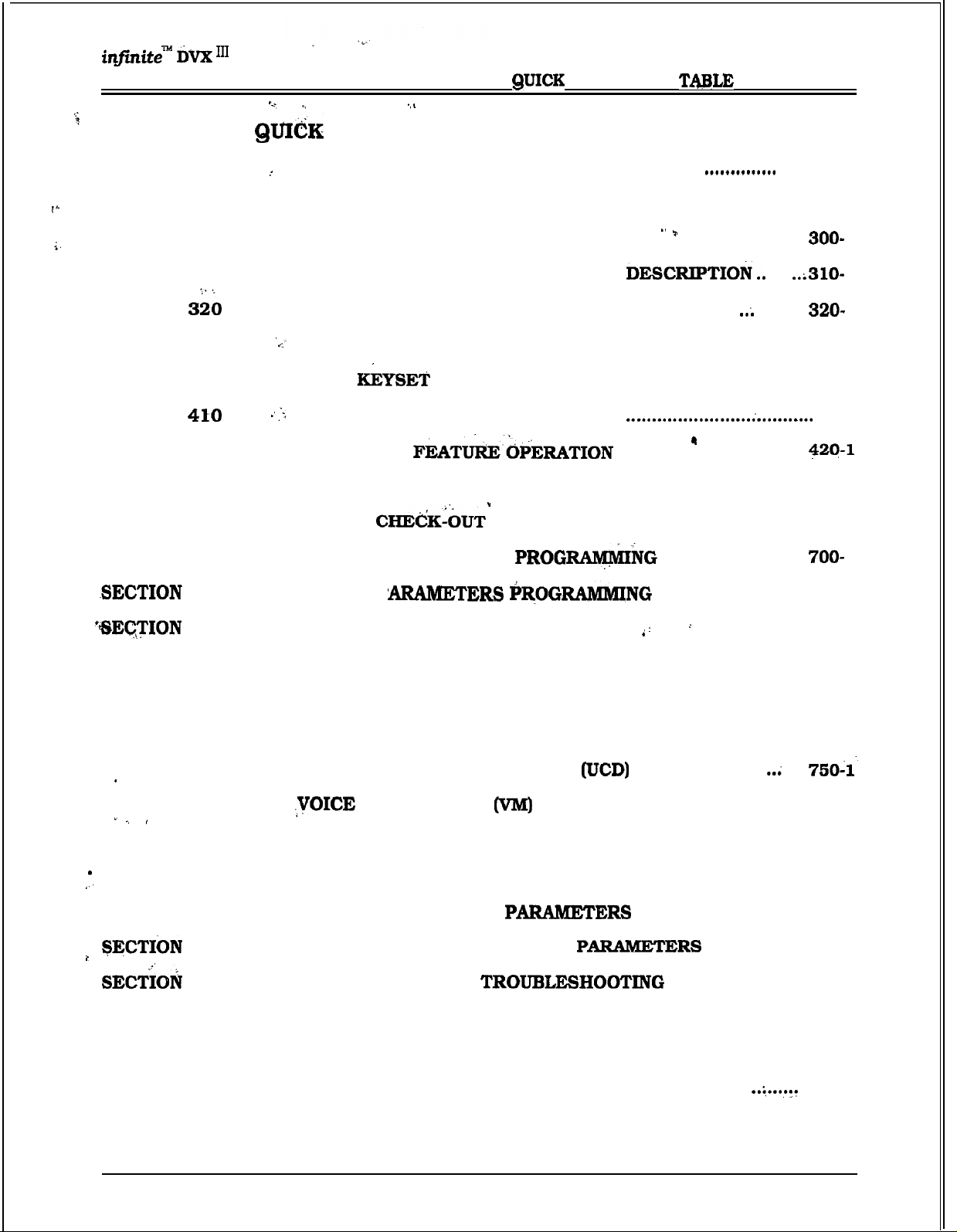
REFERENCE TABLE OF CONTENTS
REFERENCE
OF CONTENTS
SECTION 100
SECTION 200
SECTION 300
SECTION 310
SECTION
SECTION 460
SECTION 405
SECTION
SECTION 420
SECTION 500
SECTION 600
SECTION 700
710
, ‘INTRODUCTION
GENERAL DESCRIPTION
. . . . . . . . . . . . . . . . . . . . . . . . . . . . . . . . . . . . . . . . . . . . . . . . . . . . . . . .
. . . . . . . . . . . . . . . . . . . . . . . . . . . . . . . . . . . . . . . . . . . . . . . ..*......
KEY STATION FEATURE DESCRIPTION ................................
..
SINGLE LINE TELEPHONE FEATURE
‘ATTENDANT FEATURE DESCRIPTION
STATION FEATURE OPERATION
.
BASIC
SLT FEATURE OPERATION
FEATURE OPERATION
. . . . . . . . . . . . . . . .
...........................................
ATTENDANT
INSTALLATION
SYSTEM
.....................................
.............................
....................
................................
. . . . . . . . . . . . . . . . . . . . . . . . . . . . . . . . . . . . .
..................................
.
.
...............................
CUSTOMER DATA BASE
SYSTEM P
..............................
100-l
200-l
.....
.......... 320- 1
400-l
405-l
410-l
500-l
600-l
710-l
720
SECTION 730
SECTION 740
SECTION 745
SECTION 750
SECTION 755
SECTION 760
SECTION.765
SECTION 770
775
800
APPENDIX A
APPENDIX B
CO LINE ATTRIBUTES PROGRAMMING
STATION ATTRIBUTES PROGRAMMING
ICLID PROGRAMMING
............................................................
AUTOMATIC CALL DISTRIBUTION (ACD)
UNIFORM CALL DISTRIBUTION
.
MAIL GROUPS
....................................................
EXCEPTION TABLES PROGRAMMING
LEAST COST ROUTING (LCR) PROGRAMMING
INITIALIZE DATABASE
PRINTING SYSTEM DATABASE
MAINTENANCE AND
....
.
CUSTOMER DATABASE PROGRAMMING
DIGITAL SYSTEMS PART NUMBERS
.........................................
...............................
..............................
.............................
720-l
730-l
746-l
745-l’
..........................
755-l
..................................
..................
..................................
. . . . . . . . . . . . . . . . . ...775-1
...........................
760-l
..765- 1
770-l
800-l
.................................
A-l
B-l
APPENDIX C
Issue 1, February 1994
ICLID GENERAL DESCRIPTION
..................................
.....
C-L
i
Page 3
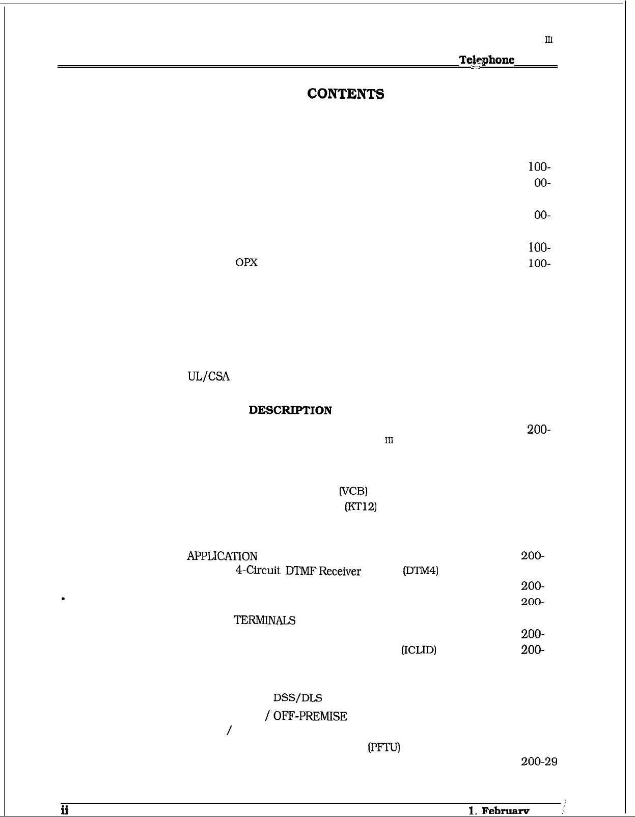
TABLE
OF CONTENTS
TABLE OF CONTENT$
Digital Key
infinite” DVX
System
SECTION 100
100.1
100.2
100.3
100.4
100.5
SECTION 200
INTRODUCTION......................................................................
PURPOSE
REGULATORY INFORMATION (U.S.A.)
A.
B. Incidence of Harm
C. Changes in Service
D. Maintenance Limitations
E. Notice of Compliance
F.
G.
REGULATORY INFORMATION (CANADIAN)
A.
B.
C. Maintenance Limitations
D. Notice of Compliance
E. OPX Circuit
TOLL FRAUD DISCLAIMER
GENERAL
.......................................................................................
............................................
Telephone Company Notification
............................................................
...........................................................
..................................................
........................................................
Hearing Aid Compatibility..
....................................................................
Notice
Explanation of Load Number
...............................................................................
..................................................
........................................................
......................................................................
......................................................
.............................................................
.......................................
...............................................
.....................................
............................................
.......................................................
100-l
100-l
100-l
1
1 OO- 1
100-l
1 OO- 1
100-l
1
1
100-2
100-2
100-2
100-2
100-2
100-2
100-3
100-3
200-l
200.1
200.2
200.3
200.4
200.5
200.6
200.7
200.8
200.9
SYSTEM TECHNOLOGY
COMMON EQUIPMENT FOR THE DVX
A.
Equipment Cabinet With Power Supply (KSU)
B.
Central Processor Unit (CPU)
C. Voice Control Board (VCB)
D.
Key Telephone Board (KT12)
E. Single Line Board (SL12)
F.
CO Loop Interface Board (C012)
MODULES ..............................................................
A.
B.
Tri-Output Power Supply
C. Backplane I/O Expansion Module
DIGITAL TERMINALS
A.
Executive (Display) Terminal
B.
Executive/PC Interface Terminal
C. Enhanced Digital Terminal
D. Basic Digital Terminal
E.
Digital DSS/DLS Console
SLT ADAPTER /.OFF-PREMISE EXTENSION MODULE
RELAY
POWER FAILURE TRANSFER UNIT (PFTU)
DATA FEATURE
SYSTEM SPECIFICATIONS AND CAPACITY
SENSOR INTERFACE MODULE
............................................................................
..................................................................
SYSTEM
............................................
................................................
.............................................
...................................................
.....................................
DTMFReceiver Module (DTM4)
................................................
..................................
....................................................................
..........................................
.............................................
....................................................
...............................................
......................................
....................................
...................................
..........................
........................
.........................
...................
.................
200-2
200-2
200-4
200-6
200-7
200-8
200-10
200-11
11
200-13
200-15
200-17
200-23
200-24
200-25
200-27
200-30
Issue
Februarv 1994
Page 4
DVX
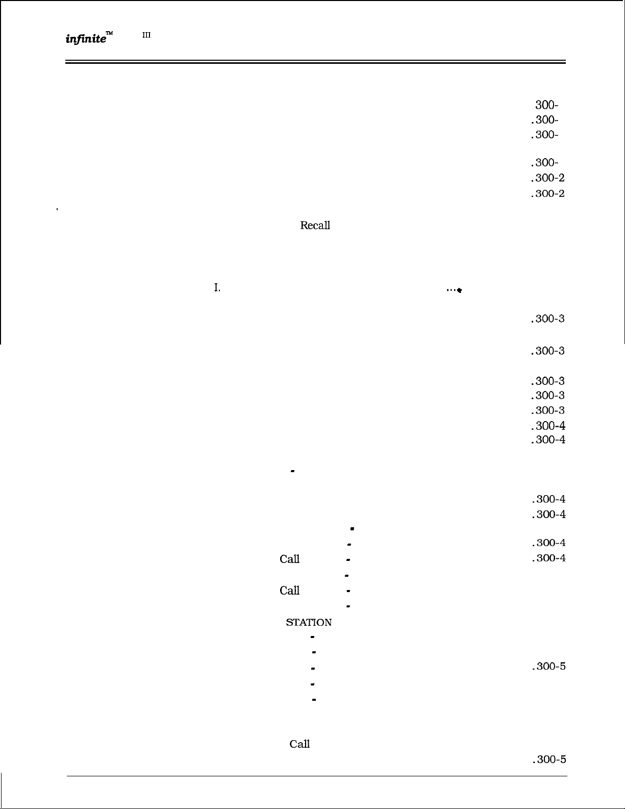
Digital Key Telephone System TABLE OF CONTENTS
SECTIQN 300 KEY STATION FEATURE DESCRIPTION
300.1
300.2
300.3
300.4
.
300.5
300.6
300.7
300.8
300.9
300.10
300.11
300.12
300.13
300.14
300.15
300.16
300.17
300.18
300.19
ACCOUNT CODES
ATTENDANT RECALL .....................................................................
AUTOMATIC
AUTOMATIC CALL DISTRIBUTION (ACD)
A.
Agent Positions
B. Alternate ACD Group Assignments
..
C.
Group
D. Incoming CO Direct Ringing
E.
No-Answer Recall Timer
F.
No-Answer Retry Timer
G. Overflow Station Assignments
H. Recorded Announcements (RAN)
Guaranteed Message Announcement
J.
Supervisor Positions
K. Supervisor/Agent Calls in Queue Display
L.
PC/ACD Interface Trace
AUTOMATIC LINE ACCESS
AUTOMATIC NIGHT SERVICE .........................................................
AUTOMATIC PAUSE INSERTION WITH SPEED DIAL ......................
AUTOMATIC PRIVACY ....................................................................
AUTOMATIC SELECTION ...............................................................
BACKGROUND MUSIC.. .................................................................
BATTERY BACK-UP (MEMORY)
BUSY LAMP FIELD (BLF) .................................................................
CALL ANNOUNCE
CALL BACK ..................................................................................... 300-4
CALL COST DISPLAY FEATURE
CALL FORWARD: PRESET ..............................................................
A.
B.
C.
D.
E. Preset
F.
CALL FORWARD:
A.
B.
C.
D.
E.
CALL PARK
CALL PICK-UP.
A.
B.
Preset Call Forward
Preset Call Forward
Preset
Preset Call Forward
Preset Call Forward
Call Forward
Call Forward
Call Forward
Call Forward
Call Forward
.....................................................................................
Directed CaII Pick-up
Group Pick-up .................................................................
...........................................................................
CALL BACK TIMER ....................................................
................................................................
Member Status
PRIVACY ..........................................................
Forward
Forward
All Calls .....................................................
Busy
Busy/No Answer.. .....................................
No Answer .................................................
Off-Net .......................................................
.................................................................................
.....................................................
..............................................
.................................................... 300-2
.....................................................
...........................................
.........................................................
....................................................
............................................................
......................................................
.....................................................
ACD Groups
Hunt Groups ..................................
Off-Net ...........................................
Stations
UCD Groups ....................................
VM Groups ......................................
.............................................................
..........................................................
........................................................
........................................... 300-5
. . . . . . . . . . . . . . . . . . . . . . . . . . . . . . .
......................................
..................................
....................................... 300-2
..... ...+
................................... 300-4
...................... 300-2
........................
300-l
1
1
1
..300- 1
1
300-2
300-2
300-2
300-2
300-3
300-3
300-4
300-4
300-5
300-5
300-5
300-5
300-5
300-5
300-5
300-5
300-5
300-5
..
Issue 1, February 1994
iii
Page 5
.
:
OF CONTENTS
:
DVX
Digital Key Telephone System
300.20
300.21
300.22
300.23
300.24
300.25
300.26
300.27
300.28
300.29
300.30
300.31
300.32
300.33
300.34
300.35
300.36
300.37
300.38
300.39
300.40
300.41
300.42
300.43
.
300.44
300.45
300.46
300.47
300.48
300.49
300.50
300.51
CALL TRANSFER
CALLER ENTERED ICLID DIGITS
CALLING STATION TONE MODE OPTION..
CAMP-ON
........................................................................................
CAMP-ON RECALL
CANNED TOLL RESTRICTION..
A.
Flex Button Programming
B.
Off-Hook Preference
C. Private Line Appearance
D.
Programmable Flash Timer
E.
Programming
CHAINING SPEED BINS..
CO LINE ACCESS
CO
CO
CLASS OF SERVICE
CONTROL (CONTACT)
CO LINE GROUPS
CO LINE IDENTIFICAT ION
CO LINE INCOMING RINGING ASSIGNMENT..
CO LINE LOOP SUPERVISION
CO LINE QUEUE
CO LINE RINGING OPTIONS
CO RING DETECT
CONFERENCE
A.
Add On Conference
B. Multi-Line Conference
C.
Unsupervised Conference
CONFERENCE ENABLE/DISABLE..
DATA FEATURE
PRINTOUT (DUMP)
DATABASE UPLOAD/DOWNLOAD
DAY/NIGHT CLASS OF SERVICE (COS)
DEFAULT
DIAL BY NAME
DIAL PULSE SENDING
DIALING PRIVILEGES
............................................................................
................................................... 300-6
......................................
..........................................................................
.......................................................
.............................................................
.................................................
..........................................................
...................................................
............................................... 300-7
and Hook-Flashes into Speed Dial . . 300-7
TRANSFER
.............................................................
............................................
.................... 300-7
...........................................................................
.........................................................
.......................................................
........................................................................... 300-7
.............................................................. 300-7
................................
......................................................... 300-8
.............................................................................
...........................................................
........................................................................... 300-8
................................................................................
...........................................................
...................................................... 300-8
.................................................
................................................
.............................................................................. 300-8
.......................................................
.................................................. 300-8
..........................................
MAPPING
..........................................................
...............................................................................
....................................................................
.....................................................................
DIRECT INWARD SYSTEM ACCESS @ISA) .....................................
A.
CO Line Group Access
B.
Programmable Access..
C.
Station Access
D.
Trunk-to-Trunk:
E.
Call Forwarding:
..................................................................
DIRECT STATION SELECTION
DIRECTED CALL PICK-UP
......................................................
.....................................................
...............................................................
......................................................
......................................................
............................................................
300-6
300-6
300-6
300-6
300-6
300-6
300-6
300-6
300-6
300-7
300-7
300-7
300-7
300-7
300-8
300-8
300-8
300-8
300-8
300-8
12
iv
Issue 1. February 1994
Page 6
Digital Key Telephone System
DIRECTORY DIALING ....................................................................
300.53
300.54
300.55
300.56
300.57
300.58
300.59
300.60
300.61
300.62
300.63
300.64
300.65
300.66
300.67
300.68
300.69
300.70
300.71
300.72
300.73
300.74
300.75
300.76
300.77
300.78
300.79
300.80
300.81
.
300.82
300.83
300.84
300.85
300.86
300.87
300.88
DISABLE OUTGOING CO LINE ACCESS.
DISTINCTIVE RINGING (User Selectable)
DO NOT DISTURB
DTMF SENDING
EMERGENCY TRANSFER
END TO END SIGNALING .............................................................
EXCLUSIVE HOLD
EXECUTIVE OVERRIDE ...............................................................
EXECUTIVE/SECRETARY TRANSFER ........................................... 300-13
EXTERNAL NIGHT RINGING .........................................................
FLASH
FLASH ON INTERCOM .................................................................
FLASH RATES (Programmable) .....................................................
FLASHWITH SPEED DIAL............................................................
FLEXIBLE ATTENDANT ................................................................. 300-13
FLEXIBLE BUTTON ASSIGNMENT ...............................................
FLEXIBLE PORT ASSIGNMENTS
FORCED ACCOUNT CODES .........................................................
FORCED LEAST COST ROUTING
GROUP CALL PICK-UP
GROUP LISTENING
HANDSET RECEIVER GAIN ........................................................... 300-14
HEADSET COMPATIBILITY............................................................ 300-14
HEADSET MODE
HEARING AID COMPATIBLE ........................................................
HOLD PREFERENCE
HOLD RECALL
HUNT GROUPS
ICLID FEATURE
IDLE SPEAKER MODE .................................................................. 300-16
INCOMING CO LINES OFF-NET FORWARD (VIA SPEED DIAL)
INTERCOM
INTERCOM SIGNALING SELECT
LAST NUMBER REDIAL (LNR) .......................................................
TABLE OF
A.
Call Pick-up
B.
Call Pick-up
A.
One-Time Do Not Disturb (DND)
...........................................................................
.....................................................................
.............................................................................
LINE/RING DOWN ................................................................
............................................................................
A.
Hunt Group Chaining ....................................................
B.
Pilot Hunting
C. Station Hunting
............................................................................ 300-15
A. Calling Number/Name Display
B.
Incoming Number/Name for SMDR Records
C.
Unanswered Call Management
CALLING
SELF TEST .....................................................................
Station.,
ACD/UCD Groups ....................................
(DND). .............................................................
.............................................................
.......................................................................
.................................................................
......................................................................
.........................................................................
....................................................................
.................................................................
.............................................................
.....................................................................
...................................................
......................................
.......................................
.....................................
...................................................
........................................
......................................
...................
.......................................
..................................................
.....
12
12
12
12
12
300-12
12
300-12
13
300-13
13
13
13
14
14
14
15
15
15
15
15
15
15
16
16
16
16
16
300-16
Issue 1, February 1994 V
Page 7
TABLE OF CONTENTS
infinite” DVX
Digital Key Telephone System
300.89
300.90 LEAST COST ROUTING
300.91
300.92
300.93
300.94 MESSAGE WAITING
300.95
300.96 MESSAGES
300.97
300.98 MUTE KEY
300.99
300.100
300.101
300.102 OFF HOOKVOICE OVER
300.103
300.104
300.105
300.106
300.107
300.108
300.109
LCD INTERACTIVE DISPLAY
A.
3-Digit Table
B.
6-Digit Table (Office Codes)
C.
Route List Tables..
D.
Insert/Delete Tables
E.
Weekly Time Tables
F.
Daily Start Time Tables
G.
Exception Tables
H.
Default LCR Data Base
I.
LOCAL NUMBER/NAME TRANSLATION TABLE
LOOP BUTTON CO LINE ACCESS
MEET ME PAGE
MESSAGE WAITING REMINDER TONE
A.
B.
C.
MUSIC ON HOLD
NAME IN DISPLAY
NIGHT SERVICE FEATURE..
NIGHT SERVICE MODE
A.
B.
C.
D. Night Class of Service (COS)
E.
F.
G. Weekly Night Mode Schedule
OFF-HOOK PREFERENCE
A.
B.
C.
D.
OFF-HOOK SIGNALING
OFF-PREMISE EXTENSIONS
ON-HOOKDIALING .......................................................................
ON LINE PROGRAMMING
PAGE/RELAY CONTROL
PAGING
Routing for Toll Information
..........................................................
...................................................................... 300-17
PERSONALIZED
Date and Time Entry to Personalized Message(s)
Messages
Personalized Message Code on a Flex Key
.................................................................................... 300-18
Automatic Night Mode Operation
External Night Ringing
Manual Operation
Night Ringing Assignments
Universal Night Answer
Auto Feature Access
Auto Line Access
Hot Line/Ring Down
Intercom Access
User Programmable Preference
........................................................................................ 300-20
Custom
..........................................................................
........................................................................
.........................................................
.......................................................
..................................................................
.............................................
..........................................................
.......................................................
........................................................
..................................................
............................................................
...................................................
...................................
............................
.................................................
.................
.
.........................................
......................................................
.............
.........................................................
.......................
.........................................................
................................................................
.................................... 300-18
...................................................
..........................................................
...........................................
............................................. 300-19
.........................................
..........................................
.............................................................. 300-19
............................................................
.......................................................
............................................................
.......................................................
.............................................................
....................................... 300-19
................................................................. 300-19
...............................................
............................................................. 300-20
...............................................................
300-18
300-18
300-20
300-20
300-20
16
16
17
17
17
17
17
18
18
18
18
18
19
19
19
19
19
19
Vi
Issue 1, February 1994
Page 8
DVX
Digital Key Telephone System
300.110
300.111
300.112
300.113
300.114
300.115
300.116
300.117
300.118
300.119
300.120
300.12 1
300.122
300.123
300.124
300.125
300.126
300.127
300.128
300.129
300.130
300.131
300.132
300.133
300.134
300.135
300.136
PAUSE TIMER.. ............................................................................
PERSONAL PARK .........................................................................
PBX DIALING CODES.. .................................................................
POOL
PREFERRED LINE ANSWER
PRIVACY RELEASE
PRIVATE LINE
PULSE-TO-TONE SWITCHOVER.. ..................................................
RANGE PROGRAMMING...............................................................
RELEASE KEY ........................................................
REMOTE ADMINISTRATION ........................................................
REMOTE SYSTEM MONITOR AND MAINTENANCE.. ...................... 300-22
SAVE NUMBER
SINGLE LINE TELEPHONE (SLT) COMPATIBILITY .........................
SPEAKERPHONE .........................................................................
STATION CLASS OF SERVICE
STATION MESSAGE DETAIL RECORDING
STATION RELOCATION FEATURE
STATION SPEED DIAL
SYSTEM CAPACITY ...................................................................... 300-23
SYSTEM HOLD .............................................................................
SYSTEM SPEED DIAL ..................................................................
TEXT MESSAGING (Silent Response) ............................................. 300-23
TOLL RESTRICTION (TABLE DFUVEN)
TRANSFER RECALL .....................................................................
UNIFORM CALL DISTRIBUTION
UNIVERSAL NIGHT ANSWER
TABLE OF CONTENTS
A.
External Paging .............................................................. 300-20
B.
Internal Paging
C.
Paging Access Restriction. . . . . . . . . . . . . . . . . . . . . . . . . . . . . . . . . . . . . . . . . . . . . . . . 300-20
OPERATION
A.
Per CO Line Option.. ......................................................
B.
Per Station Option .........................................................
..............................................................................
A.
Database Upload/Download ..........................................
A. Remote System Maintenance
B. Remote System Monitor
A.
Up to 48x96 Configuration .............................................
A.
Alternate UCD Group Assignments
B.
Auto Wrap-Up w/Timer .................................................
C.
Available/Unavailable Mode...........................................
D.
Incoming CO Direct Ringing..
E.
No-Answer RecalI Timer..
F.
No-Answer Retry Timer
G.
Overflow Station Assignments
H.
Recorded Announcements (RAN)
I.
Agent Queue Status Display ..........................................
..............................................................
..........................................................
..........................................................
......................................................................
...................
.........................................
..................................................
(SNR). ......................................................
(COS)
.............................................
.......................
.................................................
................................................................... 300-23
..........................................
.......................................... 300-23
................................
.........................................
...............................................
................................................... 300-24
........................................
..................................... 300-24
...............................................
300-20
300-2 1
300-22
300-22
300-22
300-22
300-22
1
1
1
300-2 1
1
1
1
1
300-24
Issue 1, February 1994
Page 9
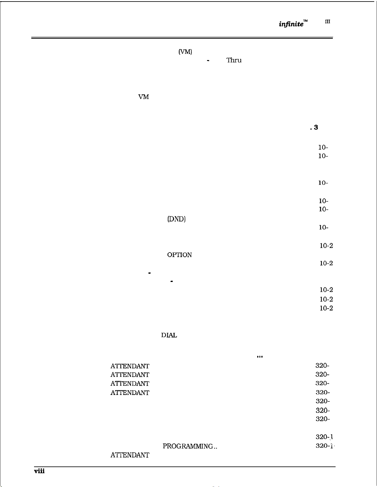
TABLE OF CONTENTS
DVX
Digital Key Telephone System
300.137
300.138
SECTION 310
310.1
310.2
310.3
310.4
310.5
310.6
310.7
310.8
310.9
310.10
310.11
310.12
310.13
310.14
310.15
310.16
310.17
310.18
310.19
310.20
310.21
310.22
310.23
VOICE MAIL GROUPS
A.
VM Disconnect Signal
B. VM In-Band Signaling Integration
C.
VM Message Waiting Indication
D.
VM Tone Mode Calling Option .........................................
E.
F.
VOLUME CONTROLS..
Transfer/Forward..................................................... 300-25
VM Transfer with ID Digits
SINGLE LINE TELEPHONE FEATURE DESCRIPTION..
ACCOUNT CODE ............................................................................
AUTOMATIC LINE ACCESS .............................................................
CALL FORWARD
CAMP ON
CONFERENCE .............................................................
CONFERENCE /WITH PERSONAL PARK.........................................
DIRECT OUTSIDE LINE GROUP ACCESS ........................................
DIRECT OUTSIDE LINE RINGING ...................................................
DIRECTED CALL PICK-UP ..............................................................
DO NOT DISTURB
GROUP CALL PICK-UP.. ..................................................................
HANDSET RECEIVER GAIN ............................................................
INTERCOM CALLING
LOOP INTERRUPT
MESSAGE WAITING/CALL BACK.. ..................................................
MESSAGES
A.
NIGHT SERVICE
OFF-HOOK PREFERENCE ..............................................................
PERSONAL PARK.. ..........................................................................
QUEUING .......................................................................................
STATION SPEED DIAL..
SYSTEM SPEED
TRANSFER ......................................................................................
........................................................................................
Messages
.............................................................................
PERSONALIZED ........................................................
Custom..
.............................................................................
...........................................................
Pass
.............................................
..................................................................
.................................. 300-25
................................... 300-25
...................................... 300-25
.......
................ 310-l
I..
................................................................
......................................................................
.............................................................
.........................................................
.................................................................. 310-2
.....................................................................
300-24
300-25
300-25
300-25
10-l
310-l
3
3
310-l
3
310-l
3
3
310-l
3
310-2
3 10-2
310-2
3 10-2
310-2
310-2
3 10-2
3 10-2
3 10-2
310-2
310-2
310-2
1
1
1
1
1
1
SECTION 320
320.1
320.2
320.3
320.4
320.5
320.6
320.7
320.8
320.9
320.10
320.11
ATTENDANT FEATURE DESCRIPTION
DISABLE OUTGOING ACCESS ...................................
OVERFLOW................................................................
OVERRIDE.................................................................
POSITION
ATI-ENDANT RECALL
AUTOMATIC NIGHT MODE .............................................................
HANDSET RECEIVER GAIN ............................................................
INCOMING CO LINE OFF-NET FORWARD.. .....................................
NIGHT SERVICE FEATURE.............................................................
TIME AND DATE
SEARCH.. ...................................................................
...................................................................
......................................................................
.................................................
......
........................
320-l
320-l
320-2
1
1
1
1
1
1
1
I.
Page 10
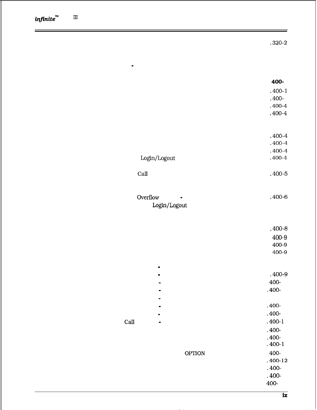
Digital Key Telephone System TABLE OF CONTENTS
320.12
320.13
320.14
320.15
320.16
SECTION 400
400.1
400.2
400.3
400.4
400.5
400.6
400.7
400.8
400.9
400.10
400.11
400.12
400.13
400.14
400.15
400.16
400.17
400.18
400.19
400.20
BUSY LAMP FIELD INDICATORS
DIRECT STATION CALLING .............................................................
MAPPING OPTIONS ......................................................................... 320-2
MESSAGES
RELEASE KEY
CUSTOM .................................................................... 320-2
.................................................................................
STATION FEATURE OPERATION
INTRODUCTION
KEY TELEPHONE STATION FEATURES ..........................................
ANSWERING AN OUTSIDE CALL..
PLACING AN OUTSIDE CALL ON HOLD..........................................
ANSWERING A RECALL ..................................................................
ACCOUNT CODES ...........................................................................
DISABLE OUTGOING CO LINE ACCESS .........................................
PLACING AN OUTSIDE CALL (Automatic Line Selection)
AUTOMATIC CALL DISTRIBUTION (ACD) .......................................
A.
Agent
B.
ACD Agent “HELP” button ................................................. 400-5
C.
ACD
D.
ACD Agent Queue Status Display .....................................
E.
ACD Available/Unavailable Mode
F.
ACD
G.
Supervisor
H.
Supervisor Monitor With Barge-In
I.
Supervisor Queue Status Display
J.
ACD Group Member Status ..............................................
BACKGROUND MUSIC (Optional) ....................................................
AUTOMATIC SELECTION
CALL BACK
CALL FORWARD:
A.
Call Forward
B.
Call Forward
C.
Call Forward
D.
Call Forward
E.
Call Forward
F.
Call Forward
G.
Call Forward
H. Call
CALL FORWARD:
CALL FORWARD:
A. Incoming CO Lines Off-Net (via speed dial)
CALLING STATION TONE MODE
CALL PARK
CALL PICK-UP:
CALL TRANSFER ..........................................................................
TRANSFERRING CO CALLS TO A STATION FORWARDED TO VM . .
.............................................................................
Qualification.....................................................
Station
................................................................
.....................................................................................
STATION
All Calls ..................................................
No Answer ................................................
Busy
Busy/No Answer.....................................
Off-Net (via speed dial) .............................
ACD or UCD Groups ...............................
Voice Mail Groups ...................................
Forward
..................................................................................
GROUP
Hunt Groups ...........................................
PRESET
CO LINES
............................................................
................................................................
....................................................
...........................................
..................................................
.................
Feature
..........................................................
........................................................
.........................................................
............................................
...................................... 400-6
Available/Unavailable Mode
Feature
......................................
..................................... 400-7
......................................
.....................
......................................
320-2
320-2
1
1
400-4
400-4
400-6
........
400-7
400-8
...400-9
...400-9
10
10
400-10
10
11
1
11
11
1
12
12
12
13
Issue 1, February 1994
Page 11
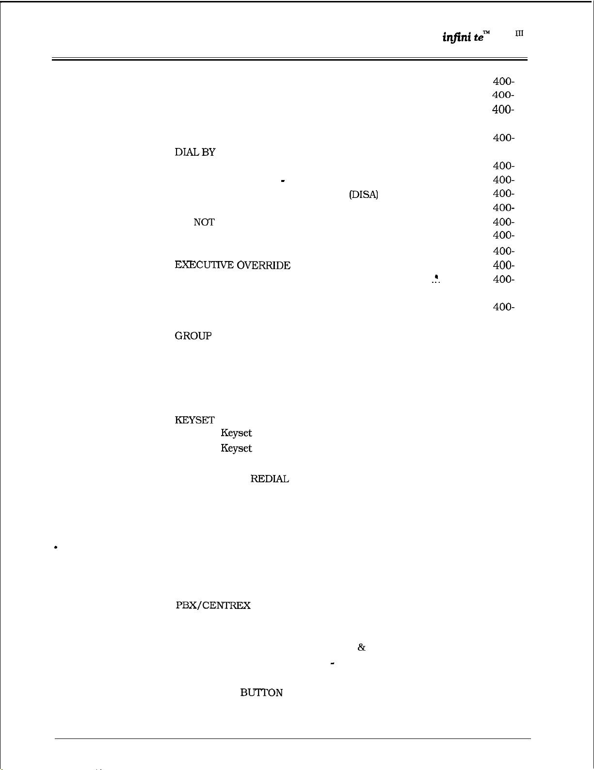
TABLE OF CONTENTS
Digital
Key
Telephone System
DVX
400.21
400.22
400.23
400.24
400.25
400.26
400.27
400.28
400.29
400.30
400.31
400.32
400.33
400.34
400.35
400.36
400.37
400.38
400.39
400.40
400.41
400.42
400.43
400.44
400.45
400.46
400.47
400.48
400.49
400.50
400.51
400.52
400.53
400.54
400.55
400.56
400.57
400.58
400.59
CAMP-ON
CO LINE ACCESS
CO LINE QUEUING
CONFERENCE COMBINATIONS....................................................
DATA FEATURE
DIRECTED CALL PICK-UP
DIRECTORY DIALING
DIRECT INWARD SYSTEM ACCESS
DISTINCTIVE RINGING
DO
A.
EXCLUSIVE HOLD ........................................................................
EXECUTIVE/SECRETARY TRANSFER
FLASH
FLASH ON INTERCOM ..................................................................
FLEXIBLE BUTTON ASSIGNMENT..
HANDSET RECEIVER GAIN
HEADSET MODE
ICLID UNANSWERED CALL MANAGEMENT TABLE
INTERCOM CALLING
INTERCOM TRANSFER.. ...............................................................
A.
B.
C.
LAST NUMBER
LEAST COST ROUTING.................................................................
MEET ME PAGE ............................................................................ 400-24
MESSAGE WAITING..
MUTE KEY..
NIGHT SERVICE FEATURE.. .........................................................
OFF-HOOK PREFERENCE
OFF HOOK VOICE OVER (OHVO). .................................................
PAGING
PERSONAL PARK
PERSONALIZED MESSAGES
A.
B.
C.
PRIME FLEX
PROGRAMMING YOUR NAME INTO THE LCD DISPLAY
PULSE-TO-TONE SWITCHOVER ...................................................
......................................................................................
.........................................................................
.......................................................................
............................................................................
NAME
DISTURB.........................................................................
One-Time Do Not Disturb
..........................................................................................
LISTENING.. .....................................................................
SELF TEST.. ....................................................................
DSS LED/Button Test .................................................... 400-23
........................................................................................
Personalized Message
Personalized Messages
Personalized Message Code On A Flex Button
............................................................................. 400-15
............................................................
Stations
.................................................................
..........................................................................
LCD/LED Test.....................................................
Button Test .........................................................
..................................................................................
TRANSFER ...........................................................
.......................................................................... 400-27
................................................................
....................................................................
................................................................
.....................................................................
PROG RAMMING ........................................
....................................................
...................................
...............................................
.......................
..............................................
..........................................................
............................................................
........................................................
Date
Custom
Time Entry..
.................................... 400-28
................
......................
....................
.................
................
13
13
13
400-13
14
16
16
17
17
18
19
19
19
400-19
19
400-20
400-2 1
400-2 1
400-22
400-22
400-22
400-23
400-23
400-23
400-23
400-24
400-24
400-24
400-24
400-25
400-25
400-25
400-26
400-26
400-27
400-27
400-28
400-28
400-28
400-29
19
X
Issue 1, February 1994
Page 12
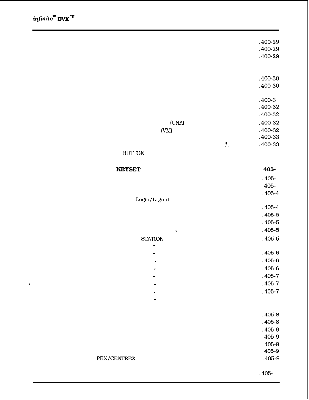
DVX
Digital Key Telephone System TABLE
OF
CONTENTS
400.60
400.61
400.62
400.63
400.64
400.65
400.66
400.67
400.68
400.69
400.70
400.71
400.72
SECTION 405
405.1
405.2 KEY TELEPHONE STATION FEATURES ...........................................
405.3
405.4
405.5 CALLING STATION TONE MODE OPTION ........................................ 405-8
405.6
405.7 CO LINE QUEUING
405.8
405.9 DO NOT DISTURB
405.10
405.11
405.12
405.13
405.14
SAVE NUMBER REDIAL.. .............................................................
PROGRAMMING PBX/CENTREX CODES ONTO FLEX BUTTON..
SPEAKERPHONE .........................................................................
STATION RELOCATION FEATURE ................................................. 400-29
STATION SPEED DIAL ................................................................... 400-30
STORING SPEED NUMBERS.. ......................................................
SYSTEM SPEED DIAL ..................................................................
TEXT MESSAGING (Silent Response)
UNIFORM CALL DISTRIBUTION
A.
UCD Calls In Queue Display..........................................
B.
UCD Available/Unavailable Mode
UNIVERSAL NIGHT ANSWER
VOICE MAIL OPERATION
A.
Voice Mail Transfer with ID..
B.
VM Tone Mode Calling Option.. ................
RELEASE
VOLUME CONTROLS ....................................................................
BASIC
INTRODUCTION..
AUTOMATIC CALL DISTRIBUTION (ACD)
A.
Agent
B.
ACD Agent “HELP” button.. ..............................................
C.
ACD Call Qualification.. ...................................................
D.
ACD Available/Unavailable Mode.....................................
E. ACD Overflow Station
CALL FORWARD:
A.
Call Forward
B.
Call Forward
C.
Call Forward
D.
Call Forward
E. Call Forward
F.
Call Forward
G.
Call Forward
H.
Call Forward
CONFERENCE WITH PERSONAL PARK.. ........................................
DIRECTED
MESSAGE WAITING
MUTE KEY
PERSONAL PARK (Flip-Flop). ........................................................
PROGRAMMING YOUR NAME INTO THE LCD DISPLAY
CALLPICK-UP
......................................................................................
........................................................................
FEATURE OPERATION
...........................................................................
Feature
............................................................
All Calls
No Answer ................................................
Busy..
Busy/No Answer.. .....................................
Off-Net (via speed dial) ..............................
ACD or UCD Groups .................................
Voice Mail Groups.....................................
Hunt Groups.. ............................................
........................................................................
..............................................................
...........................................................................
.......................................................................
TRANSFER.. ..........................................................
.............................................
(UCD)
.....................................................
.........................................
..................................
..............................................
..........................................
..................
................................
.......................................
............................................. 405-4
Available/Unavailable Mode
.....................................................
.......................................................
................
.
400-30
400-33
400-33
........
405-5
405-8
...405-9
10
1
1
1
1
Issue 1. February 1994 xl
Page 13

TABLE OF CONTENTS
Digital Key Telephone System
405.15
SECTION 410
410.1
410.2
410.3
410.4
410.5
410.6
410.7
410.8
410.9
410.10
410.11
410.12
410.13
410.14
410.15
410.16
410.17
410.18
410.19
410.20
410.21
410.22
410.23
410.24
410.25
410.26
410.27
410.28
410.29
410.30
410.31
410.32
410.33
410.34
VOLUME CONTROL
SLT FEATURE OPERATION
INTRODUCTION .............................................................................. 410-l
ACCOUNT CODE
AUTOMATIC CALL DISTRIBUTION (ACD) ........................................
A. Agent
B.
ACD Agent “HELP” button
C.
ACD Available/Unavailable Mode .....................................
CALL BACK ..................................................................................... 410-4
CALL FORWARDING
CALLING STATION TONE MODE OPTION.. ......................................
CAMP-ON
CALL PARK (System)
CALL TRANSFER: ........................................................ ,.................. 410-5
CLEAR CALL FORWARD, DND, PERSONALIZED MESSAGES ..........
CO LINE QUEUING ......................................................................... 410-5
CONFERENCE
CONFERENCE WITH PERSONAL PARK...........................................
DIRECT OUTSIDE LINE ACCESS
DIRECTED CALL PICK-UP ..............................................................
DO NOT DISTURB........................................................................... 410-5
GROUP CALL PICK-UP
PLACING CALLS ON EXCLUSIVE HOLD.. ........................................ 410-6
HANDSET RECEIVER GAIN
INTERCOM CALLING ...................................................................... 410-6
LEAST COST ROUTING.. ................................................................. 410-6
MESSAGE WAITING.. ......................................................................
OFF-HOOK PREFERENCE
PERSONALIZED MESSAGES
PAGING
MEET ME PAGE.............................................................................. 410-7
PERSONAL PARK (Flip-Flop) ...........................................................
PROGRAMMING YOUR NAME INTO THE LCD DISPLAY ..................
STATION
STORING STATION SPEED NUMBERS
SYSTEM SPEED DIAL.. ................................................................... 410-8
UNIVERSAL NIGHTANSWER (UNA) ................................................
UCD AVAILABLE/UNAVAILABLE
........................................................................................
.......................................................................................... 410-7
SPEED DIAL ....................................................................
......................................................................
...................................................
...........................................................................
Feature
.......................................................................
.......................................................................
................................................................................
TRANSFER (Flash Command to CO Line)
....................................................................
............................................................
..............................................................
..........................................................
.............................................
................................................
....................................................
...............
............................................
.................................................... 410-8
10
410-l
410-l
410-l
4
4 1 O-4
4 10-4
4 10-4
410-4
4 1 O-5
410-5
4 1 O-5
4 1 O-5
4 1 O-5
4 1 O-5
410-6
410-6
4 10-6
410-6
4 1 O-7
410-7
4 1 O-7
410-7
410-8
410-8
410-8
1
SECTION 420
420.1
420.2
420.3
420.4
420.5
ATTENDANT FEATURE OPERATION
INTRODUCTION ..............................................................................
ATTENDANT KEY TELEPHONE
ANSWERING AN OUTSIDE CALL
PLACING OUTSIDE LINE ON HOLD ................................................
ANSWERING A RECALLING OUTSIDE LINE .................................... 420-4
.....................................................
....................................
FEATURES.. ....................
420-4
420-4
Issue 1, February 1994
1
1
Page 14
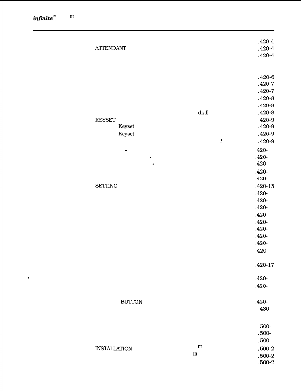
Digital Key Telephone System
TABLE OF CONTENTS
420.6
420.7
420.8
420.9
420.10
420.11
420.12
420.13
420.14
420.15
420.16
420.17
420.18
420.19
420.20
420.21
420.22
420.23
420.24
420.25
420.26
420.27
420.28
420.29
420.30
420.31
420.32
420.33
420.34
420.35
430.1
ATI-ENDANT DISABLE OUTGOING ACCESS.. .................................
OVERRIDE
ATTENDANT RECALL
DATA FEATURE
DIAL BY NAME
DISTINCTIVE RINGING..
EXECUTIVE OVERRIDE..
HANDSET RECEIVER GAIN.. ..........................................................
ICLID UNANSWERED CALL MANAGEMENT TABLE..
INTERCOM CALLING......................................................................
INCOMING CO LINES OFF-NET (via speed
SELF TEST
A. Keyset
B.
C.
DSS LED/Button Test .............................
MESSAGES
DIRECTORY DIALING
A.
Programming
NIGHT SERVICE
OFF HOOK VOICE OVER (OHVO)
SYSTEM TIME AND DATE
STORING SYSTEM SPEED NUMBERS
TEXT MESSAGING (Silent Response) .............................................
ATI’ENDANT TRANSFER SEARCH
PLACING AN OUTSIDE CALL (Automatic Line Selection)
CALL PARK ..................................................................................
DO NOT DISTURB INDICATION..
RETRIEVING A PARKED CALL
CALL TRANSFER ..........................................................................
CAMP-ON
FLEXIBLE BUTTON PROGRAMMING
MEET ME PAGE.. .........................................................................
PAGING
A.
B.
C.
RELEASE
LCD DISPLAYS ................................................................................
......................................................................................
.........................................................................................
External Paging
Internal Paging
AU Call Paging (Internal/External)
.............................................................................. 420-4
................................................................................ 420-5
LCD/LED Test.. ....................................................
Button Test...........................................................
CUSTOM
...........................................................................
................................................................
.....................................................................
.................................................................
...............................................................
......................
..............................
........................................................................
......................
..................................................................
Attendant ................................................
Attendant..
.............................................................
..............................................................
.......................................................................
.............................................
.................................................
.............................................
..........................................
................................................
...............
..................................................
......................................................
............................................. 420-17
...................................
420-18
420-18
10
11
12
14
14
15
15
17
17
17
17
17
17
17
18
18
18
1
SECTION 500
500.1
500.2
500.3
INSTALLATION
SITE PLANNING
SYSTEM COMPONENTS FOR THE DVX
Issue 1, February 1994
........................................................................
..............................................................................
A.
System
B.
Lightning Protection.,
A.
Equipment Cabinet With Power Supply (KSU)
Grounding
PLANNING FOR THE DVX
...........................................................
.......................................................
SYSTEM..
SYSTEM ........................
...................
..................
500-l
1
1
xiii
Page 15
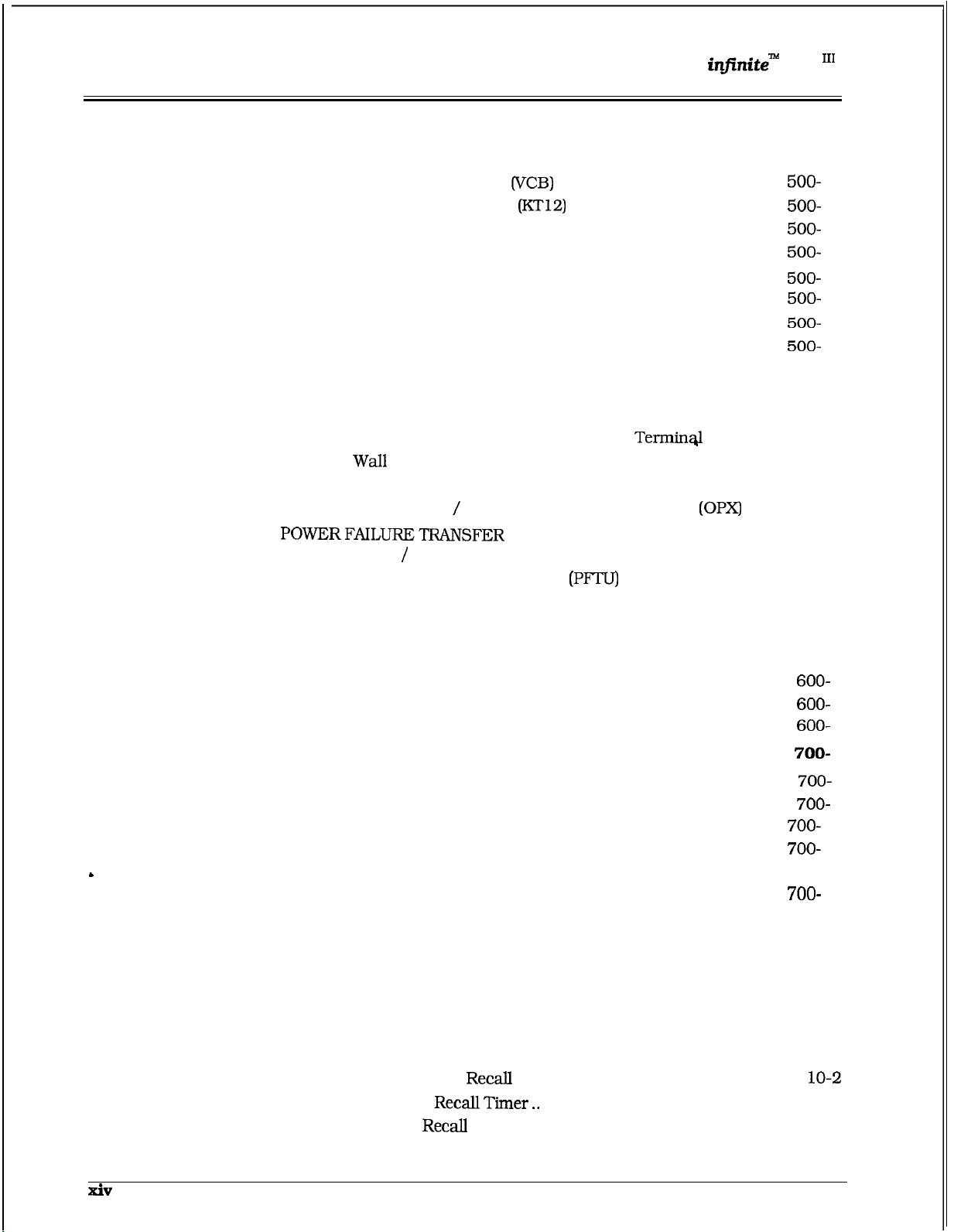
TABLE OF CONTENT9
500.4
500.5
500.6
500.7
500.8
500.9
500.10
Digital
B.
Cabinet Installation
C.
Central Processor Unit (CPU)
D.
Voice Control Board
E. Key Telephone Board
F. Single Line Board (SL12)
G.
CO Loop Interface Board (C012)
APPLICATION MODULES ..............................................................
A. 4-Circuit DTMF Receiver Module (DTM4)
Tri-Output Power Supply Installation
Backplane I/O Expansion Module Installation
DIGITAL TERMINALS
A. Digital Terminal Installation:
B. Digital DSS Console Installation:
C.
Wall Mounting the 33-Button Digital
D.
E.
F.
A.
B. Power Failure Transfer Unit
INSTALLING RECORDED ANNOUNCEMENT DEVICE (RAN).
DATA FEATURE
Mounting the 8-Button Digital Terminal..
Single Line Telephone Installation
SLT Adapter
Relay
....................................................................
Sensor Interface Module
............................................................................
..........................................................
............................................
..............................................
...........................................
.................................................
.....................................
............................................
..........................................
....................................
Off-Premise Extension Module
........................................................ 500-24
.....................................
Key
Telephone System
........................
...............................
................
................ 500-23
.................................. 500-23
........ 500-23
.................................
......... 500-30
DVX
500-2
500-6
500-20
500-20
500-20
500-20
500-24
500-24
500-3
10
11
14
16
18
1
SECTION 600
600.1
600.2
600.3
SECTION 700
700.1
700.2
700.3
700.4
700.5
700.6
700.7
700.8
SECTION 710
710.1
SYSTEM CHECK-OUT
INTRODUCTION ..............................................................................
PRELIMINARY PROCEDURES
POWER UP SEQUENCE
CUSTOMER DATA BASE PROGRAMMING
INTRODUCTION
PROGRAM MODE ENTRY (Key Station)
PROGRAM MODE ENTRY (Data Terminal or PC) ............................
BEGINNING TO PROGRAM
INITIALIZATION
CUSTOMER DATA WORKSHEETS ................................................
DATA BASE FIELDS ...................................................................... 700-12
DATABASE UPLOAD/DOWNLOAD ROUTINE
A.
Using the PC to Upload/Download thru Remote
Administration
..............................................................................
............................................................................
SYSTEM PARAMET
SYSTEM TIMERS
A.
System Hold Recall Timer..
B.
Exclusive Hold
C.
Attendant
D. Transfer Recall Timer
E.
Preset Forward Timer
............................................................................ 710-l
.............................................................
.........................................................
..................................................................
............................
...........................................
...........................................................
................................
...............................................................
ERS PROGRAMMING
...............................................
Timer..............................................
................................................... 710-3
.......................................................
.......................................................
.............................
600-l
700-l 1
700-12
700-12
710-l
710-2
7 10-2
7 1 O-3
710-4
1
1
Issue 1, February 1994
Page 16
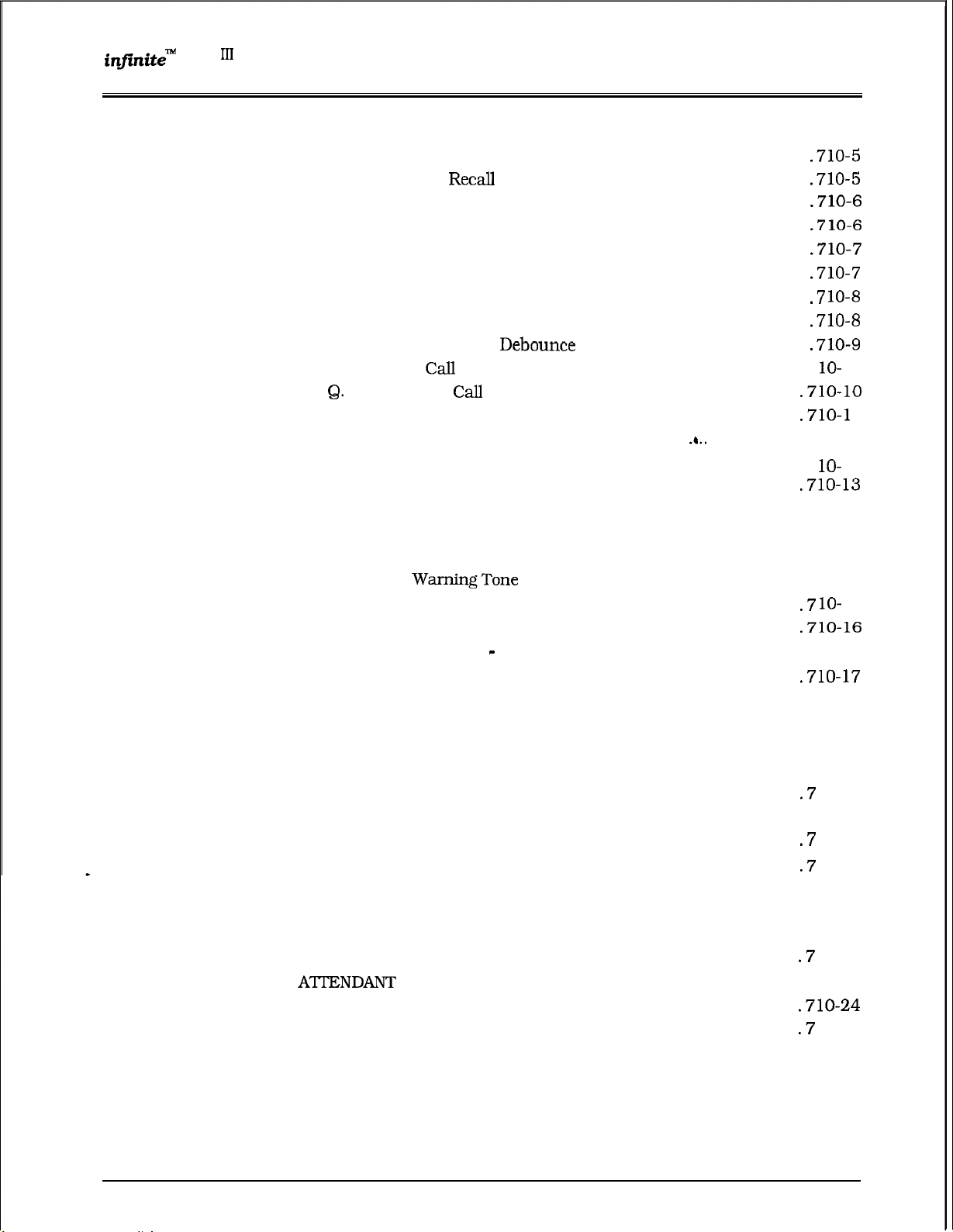
DVX
Digital Key Telephone System
F.
G.
H.
I.
J.
K.
L.
M.
N.
0.
P.
R.
S.
710.2
710.3
710.4
710.5
710.6
710.7
710.8
710.9
SYSTEM FEATURES PROGRAMMING ...........................................
A. Attendant Override
B.
C.
D.
E.
F.
G.
H.
I.
J. Idle Speaker Mode
K.
L.
M. Handset Receiver Gain
N.
ADDITIONAL SYSTEM FEATURES PROGRAMMING
A. Privacy Release Tone Option
FLASH RATES
A.
B.
C.
D.
SYSTEM TIME AND DATE
PBX DIALING CODES
EXECUTIVE/SECRETARY PAIRS
RELAY/SENSOR PROGRAMMING
A.
B.
C.
TABLE OF CONTENTS
Call Forward No/Answer Timer
Pause Timer..
Call Park Recall Timer..
Conference/DISA Timer..
Paging Timeout Timer
CO Ring Detect Timer..
SLT DTMF Receiver Timer..
Message Wait Reminder Tone..
SLT Hook Flash Timer
SLT Hook Flash Debounce Timer
SMDR Call Qualification Timer
Automatic Call Back Timer
Reminder Ring Timer..
Release Guard Timer
Hold
Preference..
External Night Ring.. ...................................................... 710-14
Executive Override Warning Tone
Page
Background Music Channel
LCR Enable
Account Codes
Group
Call Cost Display Feature
Music On Hold................................................................ 710-18
Call Qualifier Tone
Incoming CO Line Ringing
Incoming Intercom Ringing
Call Forward
Message Waiting
Programming relay for External Paging:
Programming relay for RAN Starting:.
Programming relay for Power Failure Transfer:.
Listening
(Programmable)
STATION ASSIGNMENT
...................................................................
....................................................
......................................................
....................................................
......................................................
...................................................
................................
........................................................
............................................................. 710-13
.........................................................
...................................................................
Forced
.............................................................
...................................................................
............................................................
............................................................
...................................................................
..................................................
.......................................................... 710-17
....................................................
Option ..............................................
.....................................................
.................................................. 710-25
.................................................
......................................... 710-4
.................................................
..............................................
.........................................
.....................................
.......................................
............................................
...................
...................................
...........................................
................................................ 710-18
....................
..........................................
..............................................
.............................................
............................................ 710-24
..........................
..............................
............... 710-28
10-8
7
10
710-l 1
7
12
710-14
710-15
15
710-16
710-19
1 O-20
..710-2 1
1 O-2 1
1 O-22
7 1 O-22
7 1 O-23
710-23
1 O-23
1 O-25
710-26
7 1 O-27
7 1 O-27
1
Issue 1, February 1994
xv
Page 17
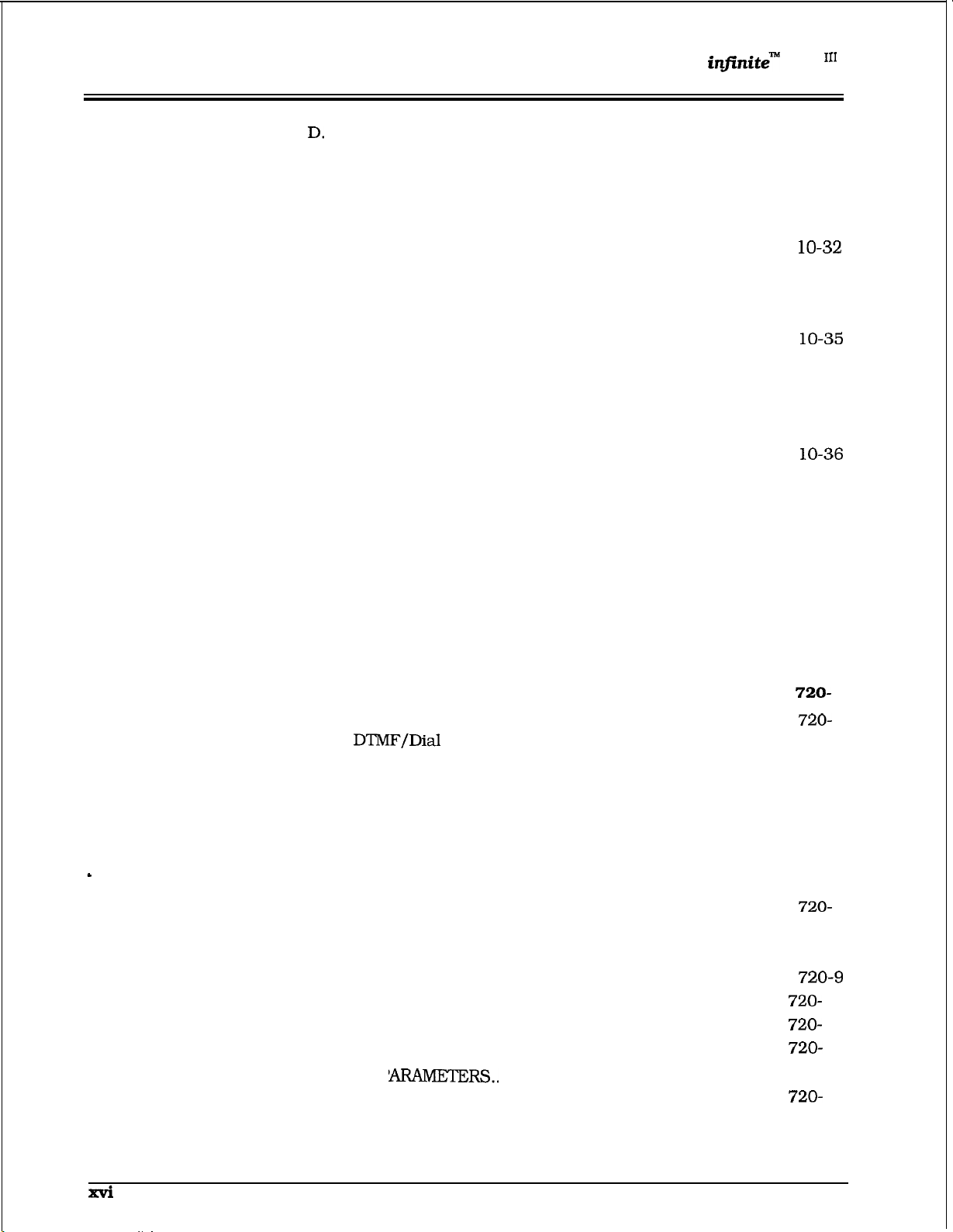
TABLE OF CONTENTS
DVX
Digital Key Telephone System
710.10
710.11
710.12
710.13
710.14
710.15
710.16
710.17
........
7 1 O-29
7 1 O-30
710-31
7
710-33
710-34
7
7 1 O-35
7 1 O-35
7 1 O-36
7
7 1 O-37
7 1 O-37
7 1 O-37
7 1 O-38
7 1 O-4 1
7 1 O-42
710-42
7 1 O-42
7 1 O-43
Programming relay for Loud Bell Control:
E.
Programming relay for CO Line Control.
F.
Assign Relay/Sensor Interface Module to a station:.
G. Program sensing circuit as a RAN Sensing (RAN END)
circuit:
BAUD RATE ASSIGNMENTS
ACCESS CODES
A.
DISA Access Code
B.
Database Admin. Password
STATION MESSAGE DETAIL RECORDING (SMDR)
A.
SMDR Enable/Disable ....................................................
B.
Long Distance/Local Assignment
C.
Character Print Assignment
D.
Baud Rate Display.. ........................................................ 710-36
E.
SMDR Port Assignments
WEEKLY NIGHT MODE SCHEDULE
A.
Automatic /Manual Operation
B.
Day of Week programming
DIRECTORY DIALING
FLEXIBLE CARD ASSIGNMENTS ..................................................
HUNT GROUPS
A.
Hunt Group Programming..
B.
Station/Pilot Hunting Assignment
LOCAL NUMBER/NAME TRANSLATION TABLE ............................
...........................................................................
.........................................................
...........................................................................
........................................................... 710-33
............................................
....................................
............................................
.................................................
..............................................
.........................................
..............................................
...................................................................
.............................................................................
............................................
..................................
.......................
........................... 710-30
.......................
SECTION 720
720.1
720.2
720.3
CO LINE ATTRIBUTES PROGRAMMING...............................
INTRODUCTION..
A.
B.
CO/PBX Programming
C.
UNA Programming..
D. DISA Trunk-to-Trunk (Per CO Line)
E.
Privacy
F. Loop Supervision Programming
G.
DISA Programming..
H.
Flash Timer Programming
I.
Line Group Programming
J.
Class of Service
K.
CO Line Ringing Assignments..
L.
CO Line Identification Display
M. Trunk Direction
N.
Ring Delay Timer
DIAL PULSE
FLEXIBLE PORT ASSIGNMENT FEATURE.....................................
............................................................................
Pulse Programming
.....................................................
..........................................................
.............................................................................
.........................................................
(COS) Programming
..............................................................
............................................................
P
......................................................... 720-12
........................................ 720-2
.................................. 720-3
........................................ 720-5
................................................
.................................................
.................................
.........................................
........................................
1
720-2
720-3
720-4
720-6
720-7
720-8
11
13
Issue 1, February 1994
Page 18
Digital
DVX
System
TABLE OF CONTENTS
SECTION 730
730.1
730.2
730.3 DIGITAL DATA INTERFACE UNIT (DDIU)
730.4 FLEXIBLE PORT ASSIGNMENT FEATURE
STATION ATTRIBUTES PROGRAMMING
INTRODUCTION
A.
Paging Access
B.
Do Not Disturb
C.
Conference Enable/Disable (Per Station)
D. Executive Override
E.
Privacy (Per Station).
F.
System Speed Dial Access..
G.
Line Queuing..
H. Preferred Line Answer..
I.
Off-Hook Voice Over.........................................................
J.
Call Forwarding
K.
Forced Least Cost Routing
L.
ACD Supervisor Monitor w/Barge-In..
M.
Executive Override Blocking
N.
CO Line Ringing Options
PAGE
INTRODUCTION ............................................................ 730-10
A. Station Identification
B.
Station Class of Service (COS)
C. Speakerphone/Headset Programming
D.
Pick-Up Group(s) Programming
E.
Paging Zone(s)
F.
Preset Call Forward Programming..
G.
CO Line Group Access
H.
I.
Off-Hook Preference Programming
J.
Flexible Button Programming
K.
Display Flexible Buttons
A.
Baud Rate Options ......................................................... 730-23
B.
Character Length Option
C.
Stop Bit(s)
.............................................................................
................................................................... 730-2
................................................................. 730-2
............................................................
........................................................
...............................................
.................................................................
.....................................................
...............................................................
.......................................
......
..............................................
...................................................
......................................................
.........................................
.............................
.......................................
Programming
Class of Service
Option ...........................................................
..........................................
.................................
....................................................
..............................................
..................................
.......................................... 730-20
.................................................
......................................
................................................
..................................... 730-25
730-l
........................... 730-3
730-3
730-5
730-6
730-7
....................
730-8
16
730-17
730-19
730-22
730-23
730-24
730-24
SECTION 740 ICLID PROGRAMMING
740.1
740.2
740.3
Issue 1, February 1994
INTRODUCTION
A.
Calling Number/Name Display
B.
Incoming Number/Name for SMDR
C.
Unanswered Call Management
ICLID RINGING ASSIGNMENT
ICLID FEATURES
A.
Enable/Disable.. ..............................................................
B.
Name in Display
C.
Baud Rate Display
D.
Port Assignment
..............................................................................
...........................................................................
............................................................
........................................
...................................
..........................................
........................................................
..............................................................
............................................................
..............................................................
740-l
740-l
740-6
1
Page 19
TABLE OF CONTENTS
DVX
Digital Key Telephone System
SECTION 745
745.1
745.2
745.3
745.4
AUTOMATIC CALL
ACD GROUP PROGRAMMING
A. Alternate ACD Group Assignment..
B. ACD Overflow Station Assignment
C.
ACD Recorded Announcement Assignment(s) (RAN)
D. ACD Supervisor Programming
E.
ACD Station Assignment(s)
ACD TIMERS
A.
B.
C. ACD Overflow Timer
D.
E. ACD No-Answer Recall Timer
F.
G. Guaranteed Message Timer
ACD RAN ANNOUNCEMENT TABLES
PC/ACD INTERFACE TRACE
A.
B. Trace Port Assignment
C. Baud Rate Display..
..................................................................................
ACD Ring Timer
ACD Message Interval Timer..
ACD Auto Wrap-Up Timer
ACD No-Answer Retry Timer..
Event Trace Enable/Disable
.........................................................
................................................................
.........................................................
........................................................
....................................................
........................................................
..........................................
...............................................
...........................................
.................................................
............................................
....................... ....................
..............................................
............................................
...........................................
.............................
...................................
....................................
..........
745-l
745-2
745-2
745-3
745-4
745-5
745-6
745-6
745-7
745-7
745-8
745-8
745-9
745-9
745-12
745-12
745.5
SECTION 750
750.1
750.2
750.3
ACD GROUP PROGRAMMING
A.
Alternate ACD Group Assignment
B.
ACD Overflow Station Assignment
C. ACD Recorded Announcement Assignment(s) (RAN).
D. ACD Supervisor Programming
E. ACD Station Assignment(s)
UNIFORM CALL DISTRIBUTION
UCD GROUP PROGRAMMING..
A.
Alternate UCD Group Assignment
B.
UCD Overflow Station Assignment..
C. UCD Recorded Announcement Assignment(s) (RAN).
D.
UCD Station Assignment(s)
UCD TIMERS
A.
B. UCD Message Interval Timer
C. UCD Overflow Timer..
D.
E. UCD No-Answer Recall Timer
F.
UCD RAN ANNOUNCEMENT TABLES
..................................................................................
UCD Ring Timer
UCD Auto Wrap-Up Timer
UCD No-Answer Retry Timer
.......................................................
...................................
..................................
........................................
.............................................
.................................
.......................................................
....................................
..................................
...............................................
...............................................................
.............................................
.......................................................
................................................
...........................................
............................................
.............................................
.......
.........
750-l
750-2
750-2
750-3
750-4
750-5
750-5
750-6
750-6
750-7
750-7
750-8
Issue 1, February 1994
Page 20
DVX
Digital Key Telephone System
TABLE OF CONTENTS
SECTION 755 VOICE MAIL GROUPS
755.1
755.2
755.3
SECTION 760
760.1
760.2
760.3
VOICE
A.
B. “Leave” Mail Index Entry
C.
D.
VOICE MAIL OUTPULSING TABLE ..................................................
A.
B. Voice Mail Disconnect Table
VOICE MAIL IN-BAND FEATURES
A.
B. Voice Mail Transfer/Forward
PROGRAMMING ..........................................................
Alternate Voice Mail Group
“Retrieve” Mail Index Entry
Station Assignment(s)
Voice Mail In-Band Signaling
Voice Mail In-Band Digits
EXCEPTION TABLES PROGRAMMING
EXCEPTION TABLES PROGRAMMING
ITEMS TO TOLL RESTRICTION ......................................
A. CO/PBX Lines
B.
Forced Account Codes.......................................................
C. SLT
D.
LCR vs.
RESTRICTION PROGRAMMING ..............................................
A. Entering Toll Table Programming
B.
Allow Table Programming.................................................
C.
Deny Table Programming
D.
Special Table Programming
E.
Displaying Toll Table Entries
Receivers
Toll Restriction..
. . . . . . . . . . . . . . . . . ..*.....................*.**.......
...............................................
...................................................
...............................................
.......................................................
...........................................
..............................................
..................................................
.................................................. 755-6
............................................
..................................
.............................................
..................................................................
........................................................
..................................................
...................................... 760-4
..................................................
............................................... 760-8
.............................................
755-l
1
755-2
755-2
755-3
755-3
755-4
755-5
755-7
1
760-2
760-2
760-4
760-7
SECTION 765 LEAST COST ROUTING
765.1
765.2
SECTION 770
770.1
INTRODUCTION.. ...........................................................................
A.
LCR Operation ..................................................................
LCR
A.
B. 6-Digit Office Code Table
C.
D.
E.
F. Daily Start Time Table
G.
H.
I.
PROGRAMMING
3-Digit Area/Office Code Table
Exception
Route List Table
Insert/Delete Table
Weekly Schedule Table
LCR Routing for Toll Information .....................................
Default
Code Table
Database
INITIALIZE DATABASE
INTRODUCTION
A. Initialize System Parameters
Initialize CO Line Attributes
..............................................................................
.........................................................
..........................................
..................................................
.......................................................
................................................................
.........................................................
....................................................
...................................................
.....................................................
. . . . . . . . . . . . . . . . . ...765-1
..................................
.............................................
.............................................
...............................................
1
765-4
765-5
765-8
11
765-12
765-13
765-14
1
770-2
770-6
Issue 1, February 1994
xix
Page 21
TABLE OF CONTENTS
Digital Key Telephone System
D.
Initialize Station and CO Port Parameters
E.
Initialize Exception Tables
F.
Initialize System Speed Numbers
G.
Initialize LCR Tables
H. Initialize System Database and Reset (all parameters) .....
I.
Initialize ICLID Parameters
J. Initialize Directory Dialing Table Parameters
K. Initialize Hunt Group Parameters
L.
Initialize ACD or UCD Group Parameters
M.
Initialize VM Group Parameters
N.
System Reset
..................................................................
..............................................
....................................
.......................................................
.............................................
...................................
......................................
.........................
...................
........................
DVX
10
13
17
SECTION 775
775.1
SECTION 800
800.1
800.2
800.3
PRINTING SYSTEM DATABASE PARAMETERS
INTRODUCTION
A. Printing System Parameters..
B. Printing CO Line Attributes
C.
Printing Station Attributes..
D.
Printing CO and Station Port Parameters..
E.
Printing Exception Tables
F.
Printing System Speed Bins..
G. Printing LCR Tables..
H. Printing Entire System Data Base..
I.
Printing ICLID Tables
J.
Printing Directory Dialing Table Parameters
K.
Printing Hunt Group Parameters
L.
Printing ACD or UCD Group Parameters.........................
M. Printing Voice Mail Group Parameters
N.
Abort Printing
..............................................................................
........................
..............................................
..............................................
...............................................
..........................................
......................................................
.................................
.....................................................
....................................
.................................................................
MAINTENANCE AND TROUBLESHOOTING
PRINTED CIRCUIT BOARD
REMOTE MAINTENANCE................................................................
A.
General Overview
B.
Overview of Maintenance Commands..
C.
Maintenance Password
D.
Exit Maintenance
E.
System Configuration
F.
CO/Station Configuration
G. Event Trace Buffer
REMOTE SYSTEM MONITOR .......................................................... 800-8
A.
General Overview
B.
Monitor Password..
C.
Help
Menu (?)
D.
Dump Memory Data
E.
Event Trace Mode..
...................................................................
TROUBLESHOOTING CHARTS
.............................................................
.....................................................
.............................................................
. . . . . . . . . . . . . . . . . . . . . . .
. . . . . . . . . . . . . . . . . . . . . . . . . . . . . . . . . . . . . . . . . . . . . . . .
. . . . . . . . . . . . . . . . . . . . . . . . . . . . . . . . . . . . . . . . . . . . . . . . . . . . . . . . . . . .
.............................................................
...........................................................
.........................................................
...........................................................
. . . . . . . . . . . . . . . . . . . . . . . . . . . . . . .
...................
...................
.
........................
....................
............................
..........................
..............................
775-l
775-2
775-4
775-6
775-8
10
775-23
775-24
775-27
775-29
775-3 1
775-33
775-35
...
800-4
800-4
800-4
800-4
800-4
800-5
800-6
800-7
800-8
800-8
800-8
800-8
800-9
1
xx
Issue 1, February 1994
Page 22

DVX
Digital Key Telephone System TABLE OF CONTENTS
APPENDIX A
APPENDIX B
APPENDIX C
1.
2.
3.
F.
Modify Memory command ..............................................
G.
Baud Rate Command......................................................
H.
Exit the Monitor mode ...................................................
CUSTOMER DATABASE PROGRAMMING
DIGITAL SYSTEMS PART NUMBERS
ICLID GENERAL DESCRIPTION
INTRODUCTION
SYSTEM CONFIGURATION .................................................................
FUNCTIONAL PERFORMANCE...........................................................
A.
B.
Incoming Number/Name SMDR
C.
Unanswered Call Management..
D.
E.
ICLID Display Phone Operation..
IMPLEMENTATION PLAN ....................................................................
A.
ICLID KTU Display Phone ....................................................
B.
Table Structures
.................................................................................
..................................................................
................................................
...........................
.................................
. . . . . . . . . . . . . . . . . . . . . . . . . . . . . . . . . . . . . . . .
............................................
...........................................
...........................................
.........................
..........................................
10
A-l
B-l
C-l
C-l
C-l
C- 1
C-2
C-2
C-2
C-2
C-2
C-4
C-4
c-5
Issue 1, February 1994
xxi
Page 23
DVX
LIST OF FIGURES Digital Key Telephone System
LIST OF FIGURES
SECTION 100 INTRODUCTION
SECTION 200 GENERAL DESCRIPTION
Figure 200-l
Figure 200-2 Central Processing Unit (CPU).
Figure 200-3 Voice Control Board
Figure 200-4 Key Telephone Board
Figure 200-5 Single Line Telephone Board (SL12)
Figure 200-6
Figure 200-6
Figure 200-7 Executive Digital Terminal
Figure 200-8 Enhanced Digital Terminal
Figure
Figure
Figure 200-15 Off-Premise Extension (OPX)
Figure
Figure
Figure
Figure 200-16 Relay
Figure
Figure
Figure 200-19 Digital Data Interface Unit (DDIU)
Basic KSU Cabinet
CO Line Board (CO12).
12-Circuit CO Line Board (CO 12)
Basic Digital Terminal
10 48-Button
16 Relay
15 Off-Premise Extension (OPX) Module
17 Power Failure Transfer Wiring Options
18 Power Failure Transfer Circuit
17 Power Failure Transfer Wiring Options
Sensor Interface Module
Sensor Interface Module
................................................................
..................................................
................................................................................
...............................................................
.....................................................................
..................................................................
.......................................................
..........................................................
.........................................................
...................................................................
..................................................................
......................................................
Console..
...........................................................
Module..
........................................................... 200-26
................................................
........................................................
..................................................
...............................................
........................................................
...............................................
wiring
...........................................
SECTION 300 KEY STATION FEATURE DESCRIPTION
.................
............................
100-l
200-l
200-3
200-5
200-6
200-7
200-8
200-10
12
200-14
16
18
200-23
200-24
200-24
200-25
200-25
200-27
200-28
300-l
Figure
Figure 300-2 Basic
1 Executive Keyset Default Button Map
Default Button Map.. .......................................................
.................................................
SECTION 310 SINGLE LINE TELEPHONE FEATURE DESCRIPTION..
SECTION 320
SECTION
Figure
1 Executive Digital Terminal
SECTION 405 BASIC
Figure
1 Basic Digital Terminal
SECTION 410 SLT FEATURE OPERATION
SECTION 420 ATTENDANT FEATURE OPERATION
Figure
1 Attendant Display Terminal
SECTION 500 INSTALLATION
Figure
Figure 500-2 Basic
Figure 500-3 Basic KSU Cabinet Mounting Dimensions..
Figure 500-4 Central Processor Unit (CPU)
Figure 500-5 RS-232C Printer Connections on CPU Board ..........................................
Figure 500-6 RS-232C Computer Connections on CPU Board
ATTENDANT FEATURE DESCRIPTION
STATION FEATURE
OPERATION
.....................................................................
FEATURE OPERATION
...........................................................................
...............................................
...................................................................
.................................................................
Basic
Cabinet Mounting Arrangement..
Equipment Cabinet...............................................................
.................................................................
..............................
.......................................
.............................
.................................
..........................................
............................................
.....................................
300-10
11
..... ..310- 1
320-l
1
400-2
405-l
405-2
410-l
420-l
420-2
500-l
500-3
500-4
500-5
500-7
500-8
xxii
Issue 1, February 1994
Page 24
DVX
Digital Key Telephone System
LIST OF FIGURES
..
SECTION 600
SECTION 700
SECTION 710 SYSTEM PARAME
Figure 500-7 Voice Control Board
Figure
Figure
Figure
Figure 500- 11 CO Line Board (CO 12)
Figure 500- 12 Backplane I/O Expansion Module Connections
Figure 500- 13 Digital Terminal Modular Block Wiring
Figure 500- 14 DigitaI Terminal WalI Mounting
Figure 500-15
Figure
Figure 500- 17 Power Failure Transfer Wiring Options
Figure 500- 18 Power Failure Transfer Circuit
Figure
Figure 500-20 Digital Data Interface Unit (DDIU) wiring..
Key Telephone Board (KT12)
Shielded Cable Terminations
Single Line Telephone Board (SL12).
Off-Premise Extension
Relay
19 CO and SLT RAN Connections..
Sensor Interface Module
SYSTEM CHECK-OUT
CUSTOMER DATA BASE PROGRAMMING
Figure 700- 1 Data Terminal Program Codes Cross Reference
Figure 700-2 Progr
Button Mapping
..................................................................
.................................................................
................................................................ 500-13
...................................................
........................................................................ 500-17
..................................
...............................................
..........................................................
Module
............................................................
..................................................
.........................................................
...............................................
..........................................................
..........................................
......................................................
.........................
.....................................
..............................................................
TERS
..........................
500-2 1
500-22
500-25
500-26
500-27
500-28
500-30
500-3 1
600-l
700-l
710-l
Figure 7
SECTION 720
1 Hook Switch Activity
.............................................................................
CO LINE ATTRIBUTES
SECTION 730 STATION ATTRIBUTES
SECTION 740 ICLID PROGRAMMING
SECTION 745
SECTION 750
SECTION 755
AUTOMATIC CALL DISTRIBUTION (ACD)
UNIFORM CALL DISTRIBUTION
VOICE MAIL GROUPS
.....................................................
...............................................
SECTION 760 EXCEPTION TABLES PROGRAMMING
SECTION 765 LEAST COST ROUTING
Figure 765- 1 LCR Flowchart
Figure 765-2 Ex: 3-Digit Area/Office Code Table Pgm Form
Figure 765-3 Ex: 6-Digit Office Code Table Pgm Form
Figure 765-4 Ex: Exception Code Table Pgm Form
Figure 765-5 Ex:
Figure 765-6 Daily Start Time
Figure 765-7 Ex:
Figure 765-8 Ex: LCR Toll Information Routing Pgm Form
Insert/Delete Pgm Form..
Daily & Weekly Start Time Tables
......................................................................................
Weekly Schedule Tables
...............................................................
PROGRAMMING
.......................................
................................................
......................................................
..........................................
...................................................
........................................
SECTION 770 INITIALIZE DATABASE PARAMETERS
............................
...........................
..........................
..............................
..............................
.................
.............................
720-l
730-l
740-l
745-l
750-l
755-l
760-l
765-l
765-7
765-10
770-l
Figure
Figure 770-2
Issue 1, February 1994
1 33-Button Default Button Mapping ........................................................ 770-7
Default Button Mapping..
.......................................................
Page 25
LIST OF FIGURES
Digital Key Telephone System
SECTION 775
Figure
Figure 775-2 DB Printout of CO Line Attributes..
Figure 775-3 DB Printout of Station Attributes
Figure 775-4 DB Printout of CO/Station Parameters
Figure 775-5 DB Printout of Exception Tables ..........................................................
Figure 775-6 DB Printout of System Speed Numbers
Figure 775-7 DB Printout of
Figure 775-9 DB Printout of ICLID Table
Figure 775- 12 DB Printout of Directory Dial Table
Figure 775-13 DB Printout of Hunt Group Parameters.. ............................................ 775-30
Figure 775-14 DB Printout of ACD Group Parameters
Figure 775-15 DB Printout of Voice Mail Group Parameters ...................................... 775-34
SECTION 800
Figure
Figure 800-2 System Configuration
Figure 800-3 CO/Station Configuration...................................................................... 800-6
Figure 800-4 Event Trace as it appears on Display
1 DB Printout of System Parameters
1 Remote Maintenance Help Menu..
PRINTING SYSTEM DATABASE PARAMETERS
...................................................................
.................................................................. 775-25
MAINTENANCE AND TROUBLESHOOTING
................................................................
APPENDIX A CUSTOMER DATABASE
.................
......................................................... 775-3
........................................................
...........................................................
.................................................. 775-9
................................................
.................................................... 775-28
...............................................
......
..........................................................
....................................................
............. ..SOO- 1
775-5
775-7
775-13
775-32
800-4
800-5
..............................
10
A-l
APPENDIX B DIGITAL SYSTEMS PART NUMBERS
APPENDIX C ICLID GENERAL DESCRIPTION
Figure 1 ICLID System Configuration
.............................................................................. C-l
............................................
. . . . . . . . . . . . . . . . . . . . . . . . . . . . . . . . . . . .
B-l
C-l
Issue 1, February 1994
Page 26
DVX
Digital Key Telephone System LIST OF TABLES
LIST OF TABLES
SECTION 100 INTRODUCTION
...............................................................
SECTION 200 GENERAL DESCRIPTION
Table 200- 1
Table 200-2 Electrical Specifications..
Table 200-3 Environmental Specifications
Table 200-4 Loop Limits
Table 200-5 Dialing Specifications
Table 200-6 FCC Registration Numbers
Table 200-7 Trunk Ordering Info:
Table
Table 200- 10 Dimensions and Weight
Table 200- 11 Digital Terminal Audible Signals
Table 200- 12 Single Line Telephone Audible Signals
Table 200- 13 OPX Telephone Audible Signals
Table
Table 200- 15 CO Line Button Visual Indicators
Table
SECTION 300
Table 300- 1 Key Station Features/Software Packages
SECTION 310
Table 3
Digital System Capacities
..........................................................................................
Miscellaneous Specifications
14 DSS/BLF Button Visual Indicators ......................................................
16 Function Button Visual Indicators
......................................................................
.......................................................................
...............................................................
...........................................................................
...................................................................
Public Network Lines
..................................................................
.......................................................................
KEY STATION FEATURE DESCRIPTION
SINGLE LINE TELEPHONE FEATURE DESCRIPTION..
1 SLT Station Features/Software Packages
.................................................
............................................ 200-33
...................................
.................................................
...........................................................
........................................................
.......................................................
....................
...........................
................................................
................................................
......
100-l
200-l
200-3 1
200-32
200-34
200-34
200-35
200-35
200-36
200-37
200-37
200-37
300-l
1
310-l
1
SECTION 320
Table 320- 1 Attendant Station Features/Software Packages
SECTION 400
Table 400- 1
Table 400-2 Flex Button
SECTION 405
Table
.
SECTION 410
Table 4
SECTION 420
Table
Table 430-l Liquid Crystal Displays (LCD) .................................................................
SECTION 500
Table 500-
Table 500-2 Single Line Telephone Board (SLl2)
Table 500-3 CO Line Board (C012)
Table 500-4
Table 500-5
Table 500-6 SMDR Printout
ATTENDANT FEATURE DESCRIPTION
STATION FEATURE OPERATION
Digital Terminal Numbering Plan..
Progr
BASIC
Basic Keyset Numbering Plan
1
Codes..
FEATURE OPERATION
..........................................................
.........................................................
.................................................................
SLT FEATURE OPERATION
1 SLT Numbering Plan
................................................................................
ATTENDANT FEATURE OPERATION
1 Attendant Numbering Plan
INSTALLATION
Key Telephone Board (KT12)
Corm A Connecting Block .............................................................
B Connecting Block .............................................................
......................................................................................
.....................................................................
................................................................
.................................................................
.......................................................
Connections
.......................................................
.............................
.......................................
......................................
............................
..............................................
................................
320-l
1
1
405-l
410-l
410-3
1
500-l
11
500-16
500-29
500-29
500-34
Issue 1, February 1994
xxv
Page 27
LIST
DVX
OF TABLE6 Digital Key Telephone System
SECTION 600 SYSTEM CHECK-OUT
. . . . . . . . . . . . . . . .
SECTION 700 CUSTOMER DATA BASE PROGRAMMING
Table 700- 1 Default Values
SECTION 710 SYSTEM
........................................................................................
ERS PROGRAMMING
SECTION 720 CO LINE ATTRIBUTES PROGRAMMING
Table 720- 1 Class of Service (COS)
.............................................................................
SECTION 730 STATION ATTRIBUTES PROGRAMMING
Table
Table 730-2 Flexible Button Display Designations ....................................................
SECTION 740 ICLID PROGRAMMING
SECTION 745
SECTION 750 UNIFORM CALL DISTRIBUTION
SECTION 755 VOICE MAIL GROUPS
SECTION 760 EXCEPTION TABLES
Table 760- 1 Class of Service (COS)
Table
SECTION 765
1 Class of Service (COS)
...........................................................................
......................................................
AUTOMATIC CALL DISTRIBUTION (ACD)
..............................
...............................................
...............................
.............................................................................
760-2 Allow/Deny Toll Table .............................................................................
LEAST COST ROUTING (LCR) PROGRAMMING
..........................
...........................
............................
...........................
....... ..(
................
................ ..765- 1
600-l
700-l
700-4
710-l
720-l
730-l
730-22
745-l
750-l
755-l
760-2
Table 765- 1 LCR Class of Service Table
SECTION 770
SECTION 775
SECTION
Table
Table 800-2 CPU Static RAM Memory Size.. ................................................................
Table 800-3 CPU EPROM Memory Size .......................................................................
Table 800-4 Single Line Board (SL12)
Table 800-5 Key Telephone Board (KT12). ...................................................................
Table 800-6 Single Line Telephone Adapter
Table 800-7 CO Line Loop Board (C012). ....................................................................
Table 800-8 Voice Control Board
Table 800-9 4-circuit DTMF Module (DTM4) ...............................................................
Table
APPENDIX A
Appendix A- 1 System Parameters
Appendix A-2 Hunt Group, ACD and UCD Group Parameters .........................................
Appendix A-2 Hunt, ACD,
Appendix A-3 Voice Mail Group
Appendix A-4 CO Line Programming (Flash 40)...............................................................
Appendix A-5 CO Line Ringing Assignment
Appendix A-6 Station Programming (Flash 50) ..............................................................
......................................................................
INITIALIZE DATABASE PARAMETERS
PRINTING SYSTEM DATABASE
MAINTENANCE AND TROUBLESHOOTING
1Central Processor Unit (CPU)
10 Backplane I/O Expansion Module
...................................................................
.........................................................................
.......................................................................
CUSTOMER DATABASE PROGRAMMING
...................................................................................
UCD Group Parameters
Parameters..
..................................................................
Chart
765-9
..............................
................
770-l
..775- 1
......................
800-l
800-2
800-2
800-2
.......................................................
800-3
800-3
800-3
800-3
................................................
..............................
.............................................
.......................................................... A-9
800-3
A-l
A-l
A-4
A-5
A-6
A-7
A- 10
1
1
Issue 1, February 1994
Page 28

DVX
Digital Key Telephone System
LIST OF TABLES
Appendix A-7 Button Assignment Chart (Flash 50)
Appendix A-8 System Speed Dial Numbers
Appendix A-9 Exception Tables (Flash 70)
Appendix A- 10 Least Cost Routing (Flash 75)
Appendix A-11 Route
Appendix A- 12 Insert/Delete Tables..
Appendix A- 13 3-Digit Area/Office Code Route List Table
Appendix A- 14 6-Digit Office Code Table
Appendix A- 15 LCR Exception Code Table
APPENDIX B
Appendix B- 1 Digital System Component List
APPENDIX C
......................................................
..................................................................
....................................................................
................................................................ A-16
.................................................................................. A-17
..........................................................................
............................................
...................................................................... .A-24
...................................................................
DIGITAL SYSTEMS PART NUMBERS
................................................................
ICLID GENERAL DESCRIPTION
............................................
..A- 2 1
..A-2 3
..A-2 5
....................................
.A- 11
.A- 12
.A- 14
B-l
B- 1
C-l
Page 29

LIST OF TABLES
DVX
Digital Key Telephone System
ISSUE CONTROL SHEET
ISSUE DATE
1
February, 1994
CHANGE
Initial Release of the
Description, Installation and Maintenance Manual.
DVX
Digital System General
Issue 1, February 1994
Page 30
DVX
Digital Key Telephone System
INTRODUCTION
SECTION 100
INTRODUCTION
100.1
PURPOSE
This manual provides the information neces-
sary to program, install, operate and maintain
the
100.2
Digital Key Telephone System.
REGULATORY INFORMATION
(U.S.A.)
D. Maintenance Limitations
The Federal Communications Commission
(FCC) has established rules which allow the
direct connection of the
Digital KeyTele-
phone System to the telephone network. Certain actions must be undertaken or understood
before the connection of customer provided
equipment is completed.
A. Telephone Company Notification
Before connecting the
Telephone System to the telephone net-
Digital Key
E. Notice of Compliance
work, the local serving telephone company
must be given advance notice of intention
to use customer provided equipment and
provided with the following information:
l
The telephone numbers to be connected
to the system.
l The Ringer Equivalence Number also
located on the KSU:
l The Universal System Ordering Code
(USOC) jack required for direct interconnection with the telephone network:
RJ2 1x
FCC Registration Numbers:
“This equipment generates and uses RF energy and if
not installed and used in accordance
tion Manual, may cause interference to Radio Communications. It has been tested and found to comply with
the limits for a Class A computing device, pursuant to
Subpart J of
designed to provide reasonable protection against
For systems configured as a key system:
(button appearances)
DLPHKG-74722-KF-E
For systems configured as a Hybrid sys-
tem: (dial access codes)
DLPHKG-74723-MF-E
environment. Operation of this equipment in a residential area is likely to cause interference, in which
case the user, at his own expense, will be required to
take whatever measures may be required to correct
the interference.”
F. Hearing Aid Compatibility
B. Incidence of Harm
If the telephone company determines that
the customer provided equipment is faulty
and possibly causing harm or interruption
to the telephone network, it should be dis-
G. OPX Circuit
connected until repairs can be made. If this
is not done, the telephone company may
temporarily disconnect service.
C. Changes in Service
The local telephone company may make
changes in its communications facilities or
procedures. If these changes should affect
the use of the
infinite
Digital Key Telephone
System or compatibility with the network,
the telephone company must give written
notice to
user to allow uninterrupted
service.
Maintenance on the infinite Digital Key
Telephone System is to be performed only
by the manufacturer or its authorized
agent. The user may not make any changes
and/or repairs except as specifically noted
in this manual. If unhuthorized alterations
or repairs are made, any remaining warranty and the software license for the system will be voided.
The infinite Digital Key Telephone System
complies with rules regarding radiation
and radio frequency emissions by Class A
computing devices.
In accordance with
FCC Standard 15 (Subpart J), the following
information must be supplied to the end
user:
CAUTION
the Instruc-
of the FCC Rules, which are
All
Digital Terminals are Hearing
Aid Compatible, as defined in Section
68.316 of Part 68 FCC Rules and Regula-
tions .
The
Digital Key Telephone System
may be equipped with Single Line Adapters
modules which provide a
registered
single line off-prem-
FCC
ise extension interface port.
Issue 1, February 1994
100-l
Page 31

INTRODUCTION
l
Each OPX port when used to support an
off-premise extension requires an
network circuit.
l An FCC registered interface such as a
is also required to connect to
the public network.
100.3
REGULATORY INFORMATION (CANADIAN)
l Department of Cormnunications (DOC)
Certification Number: 526 2933 A
l Load Number: 20
l Standard Connector: CA1
l Canadian Standards Association (CSA)
File Number: LR57228
Notice
The Canadian Department of Communica-
tions’ label identifies certified equipment.
This certification means that the equip-
ment meets certain telecommunications
network protective, operational and safety
requirements. This Department does not
guarantee the equipment will operate to
the user’s satisfaction.
Before installing this equipment, users
should ensure that it is permissible to be
connected to the facilities of the local tele-
must also be installed using an acceptable
method of connection. In some cases, the
company’s inside wiring associated with
single line individual service may be extended by means of a certified connector
assembly (telephone extension cord). The
customer should be aware that compliance
with the above condition may not prevent
degradation of service in some situations.
Repairs to certified equipment should be
made by an authorized Canadian
facility designated by the supplier.
Any repairs or alterations made by the user
to this equipment, or equipment malfunctions, may give the telecommunications
company cause to request the user to disconnect the equipment.
Users should ensure for their own protection that the electrical ground connections
of the power utility, telephone lines and
internal metallic water pipe system, if pre-
sent, are connected together. This precaution may be particularly important in rural
areas.
DVX
Digital Key Telephone System
CAUTION
Users should not attempt to make such conaections
themselves. but should contact the appropriate
electric inspection authority, or electrician, as
appropriate.
I
B. Explanation of Load Number
The Load Number (LN) assigned to each
terminal device denotes the percentage of
the total load to be connected to a telephone loop which is used by the device to
prevent overloading. The termination on a
loop may consist of any combination of
devices subject only to the requirement
that the total of the load numbers of all the
devices does not exceed 100.
C. Maintenance Limitations
Maintenance on the’ infinite Digital Key
Telephone System is to be performed only
by the manufacturer or its authorized
agent. The user may not make any changes
and/or repairs except as specifically noted
in this manual. If unauthorized alterations
or repairs are made, any remaining warranty and the software license for the system will be voided.
D. Notice of Compliance
The
Digital Key Telephone System
complies with Class A or Class B limits of
the Canadian Radio Interference Regulations. In accordance with FCC Standard 15
(Subpart J), the following information
must be supplied to the end user:
CAUTION
“This equipment generates and uses RF energy and if
installed and used in accordance
Instruction Manual, may-cause interference to Radio
Communications. It
comply with the limits for a Class A or Class B
computing device, pursuant to Subpart J or Part
the
reasonable protection against such interference, when
operated in a commercial
interference, in which case the user, at his own
expense, wlll be reqnked to take whatever measures
may be required to correct the interference.”
Rules, which are designed to provide
equipment in a residential area is likely to cause
been tested and found to
Operation
I
the
of
of
E. OPX Circuit
The
Digital Key Telephone System
may be equipped with Single Line Adapters
modules which provide a
registered
single line off-prem-
FCC
ise extension interface port.
l A DOC registered interface such as a
CA1 1 is also required to connect to the
public network.
100-2
Issue 1, February 1994
Page 32

Digital
DVX
Key
Telephone System
INTRODUCTION
100.4
The
infinite
met all safety requirements and was found be
in compliance with the Underwriters Laboratories (UL) 1459 Second Edition and Canadian
Standards Association
Standard. The infinite Digital Key Telephone
System is authorized to bear the UL and CSA
marks.
100.5
“WHILE THIS DEVICE IS DESIGNED TO BE
REASONABLY SECURE AGAINST INTRUSIONS FROM FRAUDULENT CALLERS, IT IS
BY NO MEANS INVULNERABLE TO FRAUD.
THEREFORE NO EXPRESS OR IMPLIED
WARRANTY IS MADE AGAINST SUCH
FRAUD INCLUDING INTERCONNECTION TO
THE LONG DISTANCE NETWORK”
“WHILE THIS DEVICE IS DESIGNED TO BE
REASONABLY SECURE AGAINST INVASION
OF PRIVACY, IT IS BY NO MEANS
FORE NO EXPRESS OR IMPLIED
WARRANTY IS MADE AGAINST UNLAWFUL
OR UNAUTHORIZED UTILIZATION WHICH
RESULTS IN THE INVASION OF ONE’S
RIGHT OF PRIVACY.”
TOLL FRAUD DISCLAIMER
TO SUCH INVASIONS. THERE-
SAFETY COMPLIANCE
Digital Key Telephone System has
C22.2, No. 225
.
Issue 1, February 1994
100-3
Page 33

Digital Key Telephone System
GENERAL DESCRIPTION
GENERAL DESCRIPTION
SECTION 200
200.1
The infinite family of digital key telephone sys-
tems is comprised of three fully digital
key telephone systems, the DVX
DVX
telecommunications needs of a small to medium sized business offices. All digital systems
incorporate state of the art digital technology
for command processing and voice switching
utilizing a Pulse Code Modulation/Time Division Multiplexing
module. The family of infinite Digital systems
are also engineered to allow migration of the
family of infinite digital terminals and terminal
accessories throughout the entire product line.
In addition, standard
vices are supported by use of a 2x4 SLT Expan-
sion Module on the infinite DVX
system, a Single Line Interface Board (SL12)
on the infinite DVX
adapters on all three systems.
The DVX
Digital family and fully configured supports a
maximum of 14 CO/PBX/Centrex lines and 28
digital station devices. The
or single mother board system with plug on
modules expanding the system via expansion
and expander modules configured with either
two CO/PBX/Centrex lines by four stations or
four CO/PBX/Centrex lines by eight stations.
A complete system capacity allows for use of up
to 112 time slots for stations,CO Lines, DTMF
Receivers, or data switching modules. This extends non-blocking access to all system resources.
The DVX
with power supply, Common control processor,
PCM/TDM Voice switching matrix and interface circuits for four
and interface circuits for eight Digital terminal
stations. The Basic system is also equipped
with one RS-232C I/O port, one DTMF receiver,
a connector for one Music-On-Hold channel
that also provides for background music, and
an on-board 300 baud modem that provides
access to the system for data base programming or remote maintenance and or diagnostics. Modules to provide additional I/O ports,
and an optional 1200 baud modem module can
also be added to the system.
SYSTEM TECHNOLOGY
DVX
, and
These systems are designed to meet the
voice control
telephone de-
system, a 4x8
Interface Board (CSB) on the infinite DVX
system, or
is the smallest member of the infinite
is a “flat pack”,
Basic KSU comes fully configured
lines
The DVX
family of Digital Hybrid Key Telephone systems
and supports a maximum configuration of 28
CO/PBX/Centrex lines and 56 digital station
devices. The DVX
plug in PCB’s. The system capacity is expanded
by installing four circuit CO/PBX/Centrex
lines by eight circuit station expansion PCB’s.
The complete system capacity allows for use of
up to 112 time slots for stations, CO Lines,
DTMF Receivers, or data switching Modules.
This extends virtual
system resources.
A Basic DVX
on-board power supply. The CPB which is the
only common equipment required for operation
provides the microprocessor for command
processing and Voice
CPB is also equipped with one modular
232C I/O port, a connector for one Music On
Hold channel that also provides for background
music, and an on-board 300 baud modem that
provides access to the system for data base
programming or remote maintenance and or
diagnostics. Modules to provide additional I/O
ports, and an optional 1200 baud modem module can also be added to the CPB.
The DVX
family of Digital Key Telephone systems. This
system is designed to meet the telecommunications needs of a medium to large sized business
offices. The system incorporates state of the art
Digital Technology for command processing
and voice switching utilizin a PCM/TDM voice
control module. The DVX
instruments as the DVX
tion, standard
supported by use of a Single Line Board (SL12)
and or SLA
The DVX
and fully configured supports a maximum of 48
CO/PBX/Centrex lines and 96 digital station
devices. The
with plug in modules (cards) expanding the
system via station boards and CO boards. The
boards are configured as 12 CO/PBX/Centrex
lines, 12 digital stations, or 12 single line stations. A complete system capacity allows for use
of up to 144 ports for Stations, CO Lines, or
Data switching Modules. This extends
blocking access to all system resources. In its
system is the middle system in a
is a typical KSU system with
access to all
KSU ships complete with an
switching. The
represents the larger end of the
supports the same
and DVX
telephone devices are
adapters.
is a member of the
is card slot cabinet oriented
In addi-
family
Issue 1, February 1994
Page 34

DESCRIPTION
DVX
Digital Key Telephone System
initial release the system is configured in a pre
mapped arrangement, where peripheral boards
are plugged into designated slots. The hard-
ware architecture is built so that future expan-
sion in both CO lines and Stations can be
accomplished by upgrading software and adding plug in boards.
The system KSU is powered by modular power
supplies that are mounted on the sides of the
cabinet. The cabinet is divided so that one
power supply will support a system configured
with up to 48 CO lines and 60 stations (key or
If the CO line or station requirements
exceed the aforementioned configuration, the
second power supply is needed. The second
power supply will support the
configu-
ration as well as possible future expansion re-
The
immediate and long term customer needs. Most
commonly used features are activated by direct
button selection. However, many functions
may be alternately accessed by dialing specific
codes or as another option by assigning these
dial codes to a FLEX button on a digital terminal. This permits flexible use of the infinite
Digital systems.
Future software enhancements and upgrades
are easily retrofitted and installed in the system. This will in most cases provide backward
compatibility with existing
ware further reducing the cost to upgrade or
add features to an installed system.
200.2
quirements.
The systems are installed using industry stand-
ard blocks, jacks and skinny wire cabling. This
combined with the ability to program the sys-
tem using a key terminal (digital display terminal) reduces installation cost and maintenance
The following components are necessary to op-
erate the
Refer to Appendix B for a complete
tal Key Telephone System component list with
Part
requirements.
All CO interfaces are equipped with transformer
barriers, for system classification as an FCC
fully protected system. Each CO circuit supports rotary (out-pulse) dialing and loop supervision (disconnect detection) under software
control. The DTMF tone signals and system
supervisory tones can be generated in each
or on the main PCB. All infinite Digital
systems use a proprietary tone plan for providing internal progress tones with the exception
of OPX stations which are provided with a “precise” tone plan.
The
family of digital terminals include
an Executive (display), Enhanced (non-display)
Digital Terminals, and a Basic (non-display)
Digital Terminal. Optional station terminals in-
elude a Digital DSS Console, and a Single Line
Adapter (Off-Premise Extension
adapter)
which are all upward and downward compatible to the entire
infinite
digital product line.
The system architecture allows system pro-
gramming changes to be made without interrupting state event software control of normal
communications. Call processing continues
while the customer database is updated. All
Grounding:
progrsmming changes to the customer data
base programming are made either from a digital display terminal connected to Port 01 or
from a data terminal or PC connected to either
a I/O port or remotely via the on-board 1200
baud modem (future).
product line is tailored to meet
infinite
Digital hard-
COMMON EQUIPMENT FOR THE
DVX
SYSTEM
Digital Key Telephone System.
Digi-
Equipment Cabinet w/Power Supply
l Central Processor Unit (CPU)
l Voice Control Board
l CO Line (Loop) Board
l Key Telephone Board (KT12)
l Single Line Board (SL12)
Equipment Cabinet With Power
The KSU is wall mounted. It is of metal
construction with a backplane motherboard that has 23 card slots. The CPU card
is inserted into the.CPU slot. Slots
and
4 are reserved for future common cards.
The VCB card is inserted into the VCB slot.
The remaining slots are designated Slots 1
thru 19 for peripheral cards. The system
defaults to a configuration that designates
peripheral slots 1, 2, 3 and 4 for Station
boards, peripheral slots 5, 6, 7, and 8 for
CO boards, and peripheral slots 9, 10, 11
and 12 for the remaining station boards.
Refer to Figure
1 Basic KSU Cabinet.
A No. 14 AWG copper wire should be used
to connect a ground between the ground
source and the KSU (25 feet maximum). A
two-position terminal strip (525) is located
on the lower right comer of the backplane
and is accessible through the right side of
Issue 1, February 1994
Page 35

DVX
Key Telephone System
J
GENERAL DESCRIPTION
Issue 1, February 1994
Figure 200-l Basic KSU Cabinet
200-3
Page 36

GENERAL DESCRIPTION
DVX
Digital Key Telephone System
the KSU. One terminal position can be
used to connect the ground wire from a
ground source.
Power Supply
The system KSU is powered by modular
power supplies that are mounted on the
sides of the cabinet. The cabinet is divided
so that one power supply will support a
system configured with up to 48 CO lines
and 60 stations (key or SLT). If the CO line
or station requirements exceed the aforementioned configuration, the second
power supply is needed. The power supplies provide the system with 24V power.
They are plugged into a 120V ac circuit.
The power supply and cabinet meet all
safety requirements to comply with UL
1459 Second Edition and CSA C22.2 No.
225 standards.
B.
Central Processor Unit
This plug-in card is one of two common
equipment cards required to make the system operational. The CPU card controls all
system activity. The CPU contains the
main micro-processor a 16-bit (68302), the
slave microprocessor (another
and
a real time clock. The master and slave CPU
chips are connected via a serial communications link. The CPU is responsible for all
control functions, execution of all logic operations, and control of system modules.
The master CPU also provides software and
hardware support to ensure the following:
l Watch dog timer and recovery.
l State/Event software design.
l Battery Backup of Customer Database
RAM memory.
The slave CPU ensures the following signal
processing functions are done:
l PCB status as to presence/absence of
cards for automatic software configuration setup.
l Interpret an ID code from each PCB so
that card type can be determined automatically.
l Process interrupts from peripheral
cards and scan VCB.
In addition there is one RS-232 (modular
connector) input/output port on the CPU
and a connector to support the use of an
optional Backplane I/O expansion module. The Backplane I/O Expansion Module
adds two RS-232C I/O ports to the system
for a system total of three I/O ports. A reset
(halt) push button switch is located on the
front of the PCB.
System software is provided in EPROM
memory and is installed on the CPU. The
CPU contains 5 12 kilobytes (expandable to
4MB) of EPROM memory storage and is
equipped with 256K of battery-backed
static RAM (expandable to 2MB). Provisions have been made on the card to address up to four megabytes of EPROM
memory and up to two megabytes of static
RAM.
l
A Battery jumper strap is located on the
CPU board. Jumpering from pins 1
2
disables the Battery Backup. Between
pins 2
3 enables the Battery Backup
option.
l
The CPU allows the use of either 1 Megabit or 4 megabit static RAM chips to be
used for RAM memory.
Indicators
Three green
located along the front
edge of the CPU provide an indication of the
presence
red
provide the system heartbeat
-5Vdc. Two
indication.
I/O Ports
The Central Processor Unit contains one
8-pin modular jack type comrec-
tor, I/O Port (future) located near the front
edge of the PCB. This I/O port is capable of
transmitting and receiving data at 300,
1200, 2400, 4800, and 9600 baud rates.
In the future, this I/O port can be used for
SMDR output, Remote programming thru
a data terminal or PC, ICLID output, or
interfacing with the infinite
Re-
porting package.
200-4
Issue 1, February 1994
Page 37

DVX
Digital Key Telephone System
Heartbeat-Master
GENERAL DESCRIPTION
RS-232C
Input/Output
Port
(Future)
Issue 1, February 1994
Figure
200-2
Central Processing Unit (CPU)
200-5
Page 38

GENERAL DESCRIPTION
C.
Voice Control Board
The Voice Control Board
provides
the time slot switch to control the
switching information. The system tones
are also generated on this board. The board
contains one DTMF receiver for DISA use.
Indicators
There are two
the
dc and
on the board to
dc.
Modem Interface
The Voice Control Board (VCB) contains an
“On-Board” modem that is capable of
transmitting data at a rate of 1200 baud.
The modem supports and is compatible
with the Hayes
command protocol.
Digital Key Telephone System
The Bell System (Western Electric)
ards 103 and 2 12A for modem design is
incorporated into the design of this
dem. The modem operates on-line in both
Full and Half duplex modes.
Wiring
Connections
There are two phono input connectors on
the board. One connector is for
ground music and the other is for music on
hold. There are also two potentiometers to
adjust each music source.
Hold Input
BGM
7
Adjust
MOH
7
Adjust
Clock
(future)
Not
Used
200-6
Figure 200-3 Voice Control Board
Issue 1, February 1994
Page 39

DVX
Digital Key Telephone System
GENERAL
D. Key Telephone Board (KT12)
The Key Telephone Board (KT12) provides
the interface to twelve digital telephones.
This board can be plugged into any desig-
nated station slot.
Indicators
The Key Telephone Board (KT12) contains
two
dc and -5V dc. The
to indicate the presence of
are located on the
top portion of the board.
Line/Station Interfaces
The Key Telephone Board
male 50-pin
connector on the
has one
front edge. This will interface the circuits
on the board to the MDF.
The board also provides proper fusing or
protection to complywith the requirements
of UL 1459 Second Edition and CSA C22.2
No. 225 standards.
A Digital DSS Console, a Single Line Tele-
phone Adapter
or other specifically
designed adapter with a digital interface
can be assigned to any one of the interface
circuits. The Key Station interface circuits
are protected from mis-wiring and
current.
External Paging Zones start from Card
1
4. Card Slots 9 thru
External Paging
Line Board
Keg Station Boards
Paging Zone associated with that card slot
becomes
4 for External Paging Zones 1
5
is inserted between two
represent
7. If a Single
the
Issue 1, February 1994
Figure 200-4 Key Telephone Board
200-7
Page 40

GENERAL DESCFUPTION
E.
Single Line Board (SL12)
The Single Line Telephone board provides
the interface for 12
single line
telephones. This board can be plugged into
any designated station slot. It is recommended that the Tri-Output Power Supply
be used with this card to provide the
ac and -48V dc voltages.
one Ring Generator is required per
system. One
accommodate two SL12 boards. When an
SL12 Zward is installed,
that the
installed at the same time. If 3 or more SL12
boards
1
more than 3
receivers on them can
system.
be
Power Supply
it is recommended
Receiver Module be
in the system. at
boards with DTM4
However, no
in the
Message Waiting capability comes installed on the Single Line Telephone Board.
This circuitry provides message waiting
lamps to single line telephones equipped
with message waiting lamps and supports
up to 12 Single Line Telephone Message
Waiting lamps at
dc typically across
tip and ring.
Indicators
The board contains three
the presence of
dc. The
are located on the top portion
dc,
to indicate
5V dc and -48V
of the board.
infinite” DVX
Digital Key Telephone System
Line/Station Interfaces:
The Single Line Telephone board has one
female
front edge. This interfaces the circuits on
the board to the MDF. The board has one
two-conductor molex connector to provide
an input for 9OV ac ring. A second two-conductor molex connector interfaces -48V dc
to the card. Each SL12 installed in the
system must have both
dc applied to it via these connectors. The
card also provides proper fusing or protec-
tion to comply with the requirements of UL
1459 Second Edition and CSA C22.2 No.
225 standards.
These single line telephones can be
equipped with a
Lamp
and
provides a loop interrupt of
tion. This is the duration of loop interrupt
provided to a single line port if loop interrupt is detected on a CO line that the single
line port was connected to. Also provided if
a station calls an SLT port and hangs up.
The card will support single line telephones
up to 2000 feet from the Basic KSU cabinet.
Refer to Table 200-4 Loop Limits for additional wiring information. On-premise single line telephones should present a load
to the port totaling a maximum ringer
equivalence of 2.5.
connector on the
ac and -48V
Message Waiting
R) that operate on the “tip”
leads. Additionally each circuit
dura-
200-S
Figure 200-5 Single Line Telephone Board (SL12)
Issue 1, February 1994
Page 41

infinite”” DVX
Digital Key Telephone System
F.
CO Loop Interface Board
This board interfaces 12 Loop Start CO
lines to the system. This board can be
plugged into any designated trunk slot.
Indicators
The board contains two
the presence of -5V dc and
addition, the board has 12 red
to indicate
dc. In
to
provide the status of each CO line on the
board. A lighted LED will indicate an in-use
condition, while an un-lit LED reflects an
idle state.
GENERAL
Line/Station Interfaces
The board has one female
amphenol
connector on the front edge. This will inter-
face the circuits on the board to the
CO In Use
LED’s
Issue 1, February 1994
Figure 200-6
CO Line Board
Page 42

GENERAL DESCRIPTION
infinite”” DVX
Digital Key Telephone System
200.3
A. 4-Circuit DTMF Receiver Module
APPLICATION MODULES
(DTM4)
This board provides four DTMF receivers
for SL12 boards. This board is connected
onto each SL12 board. Each SL12 board
may contain 1 DTM4 board. No more than
3 SL12 boards with DTM4 Receiver Modules on them, can be installed in the sys-
tem.
The 24V dc source will handle up to 1 amp
of current. The Ring Generator can supply
up to 5 watts of Ring voltage.
C.
Backplane I/O Expansion Module
The Backplane I/O Expansion Module is a
wall mount unit with a 36-pin input connector and four RS-232C output connec-
tors.
The Backplane I/O Expansion kit consists
of one connecting cable, and the I/O Ex-
pansion Module.
Locate the Backplane I/O Expansion Module in a location on the MDF backboard
convenient to the KSU.
Wiring
B.
The board has one molex connector at each
end that plugs onto metal pins located on
each SLT board.
Generally, one receiver will support DISA
and/or eight SLT stations under light to
moderate traific. If SLT and or DISA traffic
is heavy, additional DTMF receivers should
be added. It is also recommended to add
additional DTMF Receivers when a Voice
Mail or Auto Attendant is connected to the
system.
The Tri-Output power supply interfaces
with the Single Line Board (SL12) and contains a -48V dc supply, 24V dc supply, and
a Ring Generator. This is a wall mountable
unit and contains screw type terminals for
its connections. Each Tri-Output power
supply can accommodate two SL12 boards
for the -48V supply. The Ring Generator
portion of the Tri-Output power supply can
accommodate all SL12 boards installed in
the system.
The
a -48V dc source up to 1 amp of current.
Connections
Power Supply
power supply can provide
Issue
February 1994
Page 43

Digital Key Telephone System GENERAL DESCRIPTION
200.4 DIGITAL TERMINALS
A. Executive (Display) Terminal
The 33-button Digital Terminal is one in a
line of Digital electronic telephone terminals. The line consists of an Executive (Display) telephone, an Executive/PC Interface
telephone, an Enhanced (non-display) telephone and a Basic telephone. These telephones are designed to operate with the
new line of infinite Digital Key Systems and
PBX Systems.
The digital terminals are connected to the
KSU via a four wire (two twisted pair) connections from an appropriate electronic
terminal interface board.
LCD Display
The Executive Digital Display Terminal has
a 48 character Liquid Crystal Display. The
display provides information such as station extensions calling, Line ringing information, camp-on information, Message
waiting information and so on. The LCD
Display is a
into 3 fields:
Field 1 = Current Status (top line,
characters)
Field 2 = Date (Left half of bottom line,
12-characters)
Field 3 = Time of day (Right half of bot-
tom line, la-characters)
These fields are separately maintained by
the KSU processing to show current and
pending station activity. Each field is re-
created upon any display change except
additional digits which are added to the
end of the existing display.
The terminal communicates to the KSU
through two 64K digital channel arrangements. One channel is used as the primary
voice and data channel, and a second data
channel is reserved for future expansion.
Power is also provided to the terminal via
the four wire connection.
Buttons and
The Executive Digital terminal key board
PCB provides long life “super bright” Light
Emitting Diodes
blies that protrude through the top housing. The buttons are small rectangular in
shape with a clear end for proper LED
visibility and diffusion. The 33-button
Digital Terminal has 33-buttons all containing
buttons plus a 12-key dial pad.
character display divided
and button assem-
except the Pickup and Flash
The Executive Digital Terminal scans the
key board for dial pad and button
bounces and depressions for command
transmission to the KSU. The
the following buttons defined as follows:
Display and Non-Display
12 Dial Key Pad*
24 Flexible Buttons
1 ON/OFF button (fixed)
1 MUTE button (fixed)
1 SPEED button (fixed)
1 FLASH button (fixed)
1
1 HOLD button (fixed)
1 CAMP-ON button (fixed)
1 MSG button
1 PICKUP button (fixed)
* All buttons except the 12-key dial pad,
Pickup and Flash button have an LED
associated with it. Refer to Figure 200-7
Executive Digital Terminal.
Speakerphone
Each Executive Digital Terminal is
equipped with a unit that enables the telephone to be used handsfree in two-way
conversations. The user activates the
speakerphone by pressing the ON/OFF
button (LED lights steady). To terminate a
speakerphone call, the ON/OFF button is
toggled OFF (LED extinguished). The
MUTE feature is used in conjunction with
the speakerphone option. To mute the
speakerphone microphone, the MUTE button is pressed (LED lights steady). To reactivate the microphone, the MUTE button is
pushed again (LED extinguished).
Several programmable options control the
speakerphone operation. Each digital terminal can be programmed for full speakerphone operation, or monitor/On-Hook
dialing capabilities with no full speaker
phone operation.
When Automatic Pre-selection is enabled
at the station when any button is pressed
(i.e. CO, DSS, Page etc.
speakerphone is automatically activated.
button (fixed)
the station and
has
Issue 1, February 1994
200-l 1
Page 44

GENERAL DESCRIPTION
Digital
Key
Telephone System
DVX
200-12
Figure 200-7 Executive Digital Terminal
Issue 1, February 1994
Page 45

DVX
Digital Key Telephone System
GENERAL DESCRIPTION
Volume Controls
Separate “slide” switches are provided on
the front of the
adjust the volume of the voice and tones
presented to the terminal speaker.
The speaker volume (center switch) will
control all voice signals sent to the
speaker i.e. Speaker Phone conversations, BGM, and Page announcements.
The ringing volume (right switch) will
control all tone signals presented to the
speaker i.e.: Ringing, splash tones,
Camp-On etc.. . Muted ringing will also
be controlled by the ringing volume slide
switch. The muted ringing volume will
be proportionately quieter than normal
ringing based on the current switch setting.
Switch
A three position slide switch is located on
the front of the Digital Display Terminal
that controls the method of receiving inter-
com calls.
The “HF” position allows intercom call
announce with hands free reply.
The
intercom calls only.
The ‘TN” position provides Tone only
intercom ringing.
This switch allows users to set and control
the method in which they receive their
intercom calls. However, a dial code that
users can dial before placing an intercom
call can override a called station’s switch
setting of HF or PV to force the station to
Tone ring.
Directory Tray
Each Executive Digital Terminal is
equipped with a slide-out Directory Tray
accessed from the front of the digital termi-
nal.
Mounting
The Wall Mount Bracket is designed to
allow the 33-button digital terminal to be
wall mounted on industry standard 630
type wall jacks. A 4-inch line cord is also
provided as a standard item with each wall
bracket.
Handset/Line Cords
The 33-button Digital Terminal uses a
color coordinated Euro-Style handset with
a matching 12-foot handset cord. A
four conductor base line cord is included
with every Terminal.
position allows Call Announce
Digital Terminal to
The Executive Digital Terminal uses an
electret-type transmitter. Compatible
headsets can be plugged into the Terminals handset jack for headset operation.
B. Executive/PC Interface Terminal
(ICLID)
The Executive/PC Interface Terminal is
similar to the Executive Display model and
all of the information listed above applies
to the Executive/PC Interface model except
this terminal is used to deliver specific data
messages identifying call states to a device
attached to the phone via a serial channel
following the data transmission requirements of RS-232C. The interface parameters to be used are
data bits, and 1 stop bit. This feature will
deliver ICLID data to a Personal Computer
attached to the phone for look-up of customer records and subsequent processing
by the individual answering the telephone
call. Calls can also originate from the Per-
sonal Computer through the digital terminal.
The Executive/PC Interface terminal provides transmit, receive, and ground data
lines from the phone micro-processor
which are used on command from the KSU
to output information. The use of this capability would be to output the ICLID in-
formation to a PC attached to the phone.
The VODAVI Call Tracker software pro-
gram is available to support these Caller ID
applications. Future use could be made of
this capability for low speed data provided
to equipment attached to the phone.
C. Enhanced Digital Terminal
The Enhanced Digital Terminal is similar
to the 33-button Executive Digital Termi-
nal and all of the information listed above
applies except there is no LCD display.
no parity, 8
Issue 1, February 1994
200-13
Page 46

DESCRIPTION
DVX
Digital Key Telephone System
200-14
Figure 200-S Enhanced Digital Terminal
Issue 1, February 1994
Page 47

Digital Key Telephone System
GENERAL DESCRIPTION
D. Basic Digital Terminal
The Basic Digital Terminal is one in a line
of digital electronic telephone terminals.
This telephone is designed to operate with
the line of
PBX Systems.
Buttons and
The Basic Digital terminal key board PCB
provides long life “super bright” Light Emitting Diodes
that protrude through the top housing. The
buttons are small rectangular in shape
with a clear end for proper LED visibility
and diffusion. The Basic Digital Terminal
has eight buttons all containing
a 12-key dial pad.
The Basic Digital Terminal scans the key
board for dial pad and button debounces
and depressions for command transmis-
sion to the KSU. The keyset has the follow-
ing buttons defined as follows:
12 Dial Key Pad*
8 buttons, 4 of which are flexible
1 DSS STA 100 button (flexible)
1 DSS STA 101 button (flexible)
1 LOOP button (flexible)
1 POOL button (flexible)
1 SPEED button (fixed)
1 ON/OFF button (fixed)
1
1 HOLD button (fixed)
* All buttons except the 12 key dial pad,
have an LED associated with it. Refer to
Figure
Speakerphone
Each Basic Digital Terminal is equipped
with a unit that enables the telephone to
be used handsfree in two-way conversations. The user activates the speakerphone
by pressing the ON/OFF button (LED
lights steady). To terminate a speakerphone call, the ON/OFF button is toggled
OFF (LED extinguished). The MUTE feature is used in conjunction with the speak-
erphone option. To mute the speakerphone
microphone, the pre-programmed MUTE
flex button is pressed (LED lights steady).
To reactivate the microphone, the MUTE
button is pushed again (LED extin-
Digital Key Systems and
and button assemblies
plus
button (fixed)
Basic Digital Terminal.
Several programmable options control the
speakerphone operation. Each digital terminal can be programmed for full speakerphone operation, or monitor/On-Hook
dialing capabilities with no full speaker
phone operation.
When Automatic Pre-selection is enabled
at the station when any button is pressed
(i.e.. CO, DSS, Page etc...) the station and
speakerphone is automatically activated.
Volume Control
A “slide” switch is provided on the front of
the
the volume of the voice and tones presented to the terminal speaker.
The “slide” switch controls the speaker
volume which controls all voice signals
sent to the
conversations, BGM, and Page announcements.
The same “slide” switch also controls the
ringing volume which controls all tone
signals presented to the speaker i.e..
Ringing, splash tones, Camp-On etc...
Muted ringing is also controlled by the
slide switch. The muted ringing volume
will be proportionately quieter than normal ringing based on the current switch
setting.
Directory Tray
Each Basic Digital Terminal is equipped
with a slide-out Directory Tray accessed
from the front of the digital terminal.
The &button Wall Mount Bracket is de-
signed to allow the
nal to be wall mounted on industry
standard 630 type wall jacks. A 4-inch line
cord is also provided as a standard item
with each bracket.
Handset/Line Cords
The Basic Digital Terminal uses a color
coordinated Euro-Style handset with a
matching 12-foot handset cord. A
four conductor base line cord is included
The Basic Digital Terminal uses an
can be plugged into the Terminals handset
jack for headset operation.
Basic Digital Terminal to adjust
i.e.. Speaker Phone
Digital Termi-
transmitter. Compatible headsets
Issue
February 1994
200-15
Page 48

GENERAL DESCRIPTION
DVX
Digital Key Telephone System
Figure
Basic Digital Terminal
Issue 1, February 1994
Page 49

DVX
Digital Key Telephone System
DESCRIPTION
E. Digital
Console
The Digital Direct Station Selector /Direct
Line Selector
Consoles can be
installed in place of any digital terminal
circuit. The
Digital Console was
designed in a housing similar in looks to
the 33-button digital terminal.
The Direct Station Selector/Direct Line Se-
lector
the family of
modular in nature. The
Console to be used with
digital systems is
console
provides 48 buttons (4 columns of 12 buttons) and requires a separate four-conductor line cord connected to a digital terminal
station port.
The
Console unit can access
Stations, Direct Appearing CO Lines, or
features that may be assigned to any of the
flexible buttons.
The
be programmed onto
buttons: ACD Agent or Supervisor
Camp-On,
Personal Park, Voice
mode. These features can however
onto keuset
NOT
Console
Call Forward
and Headset
buttons.
to
be
A
unit may be assigned to one of
the different MAP configurations available.
Any one of the four MAP configurations
may be assigned to the
and any
number of maps may be assigned to one
station. However, MAPS that have buttons
assigned as CO lines cannot be changed,
buttons assigned as Stations can be
changed by the user. Up to three
units may be assigned to one station.
Console Button Mapping
The buttons on the
console can
be mapped with either a combination of
fixed and flexible or completely flexible but-
tons where the station user may change
the button programming to suit their
needs.
There are four pre-defined
for the
Console with default Button
Programming. Refer to Figure
Console Map
Figure 200-12 DSS
11 DSS
Console Map 2, and Figure 200-13 DSS
Console Map 3, and Figure 200-14 DSS
Console Map 4 for a button layout of each
DSS Console Map.
Issue 1, February 1994
200-17
Page 50

GENERAL DESCRIPTION
DVX
Digital Key Telephone System
200-18
Figure 200-10
Console
Issue 1, February 1994
Page 51

DVX III
Digital Key Telephone System GENERAL
MAP # 1 has by default the first 12 CO lines and the first 36 Stations lOO- 135. This provides a default
layout of a 12x36 configuration.
STA 100
STA 104
STA 116
STA 124
STA 128
LINE 6
Issue 1. February 1994
Figure 200-l 1 DSS Console Map 1
200-19
Page 52

GENERAL
DESCRIPTION
DVX
Digital Key Telephone System
MAP
changed by the station user. This map can be duplicated on another DSS/DL.S Console and assigned
to the same station.
has by default the first 48 Stations, 100-147. All buttons on Map
STA 100
STA 115
are flexible and can be
STA 128
I
Figure 200-12 DSS Console Map 2
200-20
Issue 1, February 1994
Page 53

DVX
Digital Key Telephone System
GENERAL DESCRIPTION
MAP #3 by default is intended to be used with Map #2 in that it has the remaining stations, 148- 195
to provide a full Station mapping. All of the buttons on Map #3 are flexible and can be changed by the
user. This map can be duplicated on another
Console and assigned to the same station.
STA 150
Issue 1, February 1994
STA179
Figure 200-13 DSS Console Map 3
Page 54

GENERAL DESCRIPTION
MAP
by default contains all 48 CO Lines to provide a full CO Line mapping.
DVX
Digital Key Telephone System
LINE 1
LINE 16
200-22
Figure 200-14 DSS Console Map 4
Issue 1, February 1994
Page 55

Digital Key Telephone System
GENERAL DESCRIPTION
200.5 SLT ADAPTER
EXTENSION MODULE
This external module provides the interface for
one long loop (OPX) single line telephone (2500
type) extension. This module requires a
rately provided
dc power supply to provide
the necessary current for long loop applications
and to support ring generation. This module is
OFF-PREMISE
The OPX box meets the requirements of the FCC
for connection to the telephone (Telco) network.
Telephones connected to the OPX box must be
DTMF only (2500 type).
This module also provides for one Power Fail
circuit in the event of an AC power failure and
contains its own
wired to and interfaces with a digital terminal
(key station) port from the infinite DVX
Sys-
tem.
TR
MDF
FIT
RR
STATION
CONNECTING
BLOCK
receiver..
Tip
MODULAR
CABLE
SLT TipSLT Ring 1 /
Customer Provided
amp per OPX unit
Red to Phone
dc Power Supply
Black to Trunk Tip
Yellow to Trunk Ring
Figure 200-15 Off-Premise Extension (OPX) Module
Issue 1, February 1994
200-23
Page 56

DESCRIPTION
Digital Key Telephone System
200.6 RELAY
MODULE
The Relay Sensor @terface Module connects to
the
DVX System using one digital
station port and provides three relay activated
contacts and three sensing circuits. The system
will support up to 4 Relay/Sensor Modules. The
relays provide for applications such as Loud
SENSOR INTERFACE
and additional applications as software will
permit. The sensing circuits provide for such
applications as RAN Stop (end of message) and
other applications as developed and allowed by
software.
An external power source is required to drive
equipment connected to the relay contacts. The
contacts are rated at 24V dc max at 1 amp.
Bell Control contacts, CO Line control contacts,
RAN Start contacts, Page Relays, Power Fail
contact
GREEN
STATION
CONNECTING
BLOCK
TIP
RING
RCVE TIP
RCVE RING
MODULAR
CABLE
24 VDC
Power Supply
or 24VDC 1 Amp Power Supply
(Customer Provided)
1 Amp Max.
Device Output Relay
(dry contacts)
(ie: RAN Device)
RAN Device
Power Failure Transfer
I
NOTE: RAN device does not
require external power supply
1
200-24
Figure 200-16 Relay
Sensor Interface Module
Issue 1, February 1994
Page 57

DVX
Digital Key Telephone System
GENERAL DESCRIPTION
200.7 POWER FAILURE TRANSFER
This unit provides the relay transfer circuits for
With loss of power to the system or a failure of
system processing, the
connect up to twelve CO lines to prewired
up to 12 CO lines in the event of a power or
processor failure. The unit is housed in its own
enclosure and mounts external to the KSU.
Activation of the
relays is controlled by the
Relay/Sensor Interface Module that is
grammed for
A customer provided 12V dc
stored, the PFTU will automatically restore the
CO
These SLT stations do not have to be used for
intercom, but can be if so desired.
power supply is required to operate the unit.
There is a manual switch that activates the
for testing purposes.
SLT RING IN
will automatically
type telephones. When power is re-
and stations to normal operation.
(SLT or DEVICE)
Power Fallwe Transfer Unit (PFTU)
Method
Method
Customer
Provided
+
1 AMP
RELAY
INTERFACE MODULE
SENSOR
Figure 200-17 Power Failure Transfer Wiring Options
Issue 1, February 1994
200-25
Page 58

GENERAL DESCRIPTION
-------------
MDF
co12
SPARE
TIP OUT
_____
---
infinite”” DVX
Digital Key Telephone System
POWER FAILURE TRANSFER UNIT
I
CHAMP CONN 1
I
I
W/OR
I
I
I
I
I
I
I
NOTE:
shown in power
fail mode
f
SINGLE LINE
INTERFACE BOARD
NOTE: Connection to
Interface is optional
RING OUT
A
I
I
SIX CIRCUITS
I
I
CHAMP CONN 2
SIX CIRCUITS
200-26
Figure
Power
Transfer Circuit
Issue 1, February 1994
Page 59

DVX
Digital Key Telephone System
GENERAL DESCRIPTION
200.8
The Data Feature is a time division switched,
point to point data transmission capability
which permits simultaneous (on the same sys-
DATA FEATURE
The data connector of the Digital Data Interface
Unit (DDIU) is a 25-pin, type D connector which
is configured as Data Communications Equipment with the following
tem but not the same port) voice and data
communications. The Data Feature offers the
ability to transmit data information between
personal computers, printers, plotters, modems, CRT terminals, and main frame computer ports.
To establish a Data call, a Digital Data Interface
Unit (DDIU) is required to be connected to each
data communications device. Data information
can be switched through the system at speeds
of 300, 1200, 2400, 4800, 9600,
asynchronous. Refer to Figure 200-
19 Digital Data Interface Unit (DDIU) wiring
The Digital Data Interface Unit (DDIU) is wired
and
The following diagram will aid in the design of
cables to connect the many different configurations of data communications devices.
to the infinite Digital Key Telephone Systems
like a digital telephone, and requires one sta-
DTE
tion port.
All connections to the DDIU are made on the
back panel. The back panel has a modular jack
and a DB-25 type connector. The modularjack,
labeled KSU, is used to connect the DDIU to the
station port of the system. The DB-25 connector
SIG GN
RTS
CTS
DSR
SRTS
SDCD
supports an RS-232C connection and is used
to connect the data device to the system.
RX CLK
A green LED lights to indicate the DDIU is
properly wired to the system.
Connection of the individual data communica-
tion devices requires that the installer be famil-
iar with data communications terms, and has
access to the appropriate information for connecting the variety of data communications de-
vices that may be encountered. This
information consists of, but is not limited to:
1.
Is the device configured as data terminal
equipment (DTE), or data communica-
tions equipment (DCE.
2.
What pin on the RS-232C type connector
performs what function?
3. What signal leads are required to make the
device operate?
When planning the installation of the data feature, use a digital display phone at any location
that is to originate a data connection. A DDIU
can only be called; it cannot originate a connec-
tion. A DDIU would typically be used in con-
junction with the digital display phone. A DDIU
would typically be connected to a printer,or a
MODEM.
The station wiring for a digital display phone
and a DDIU are identical.
configurations.
DIRECTION
I
DCE
DCE
Digital Systems Data Switching
MODEM
GND 1 1 GND
TD3
7SG
Modem to DDIU Cable
2RD
3TD
Issue 1, February 1994
200-27
Page 60

GENERAL
GREEN
STATION
CONNECTING
BLOCK
TR
RT
RR
MDF
infinite””
DVX
Digital Key Telephone System
MODULAR
CABLE
KSU
OFF
Figure 200-19 Digital Data Interface Unit
To Data Device
wiring
Issue
February 1994
Page 61

DVX
Digital Key Telephone System
Conditions:
PC
GND
SG7
RTS 4
DTR 20
I
Computer to
Cable
To establish a connection to any idle data port:
1.
A user with an associated DDIU dials the
station number of the DDIU or the group
access number of the group that the DDIU
has been inserted into or presses a DSS
button representing the DDIU. The digital
key system will then determine the baud
rate setting for the called DDIU and convert the user’s associated DDIU to the
same baud rate. The system will then
complete the connection.
A second method to establish a connection
between two DDIUs is done by the first atten-
dant.
1. The first attendant dials the extension
number of one data unit. Dial tone is
received and the display will show the
BAUD RATE.
2.
Then dials the station number of the sec-
ond data unit, confirmation tone is heard.
To break down an established connection:
1.
The station user dials his associated DDIU
number or press the DSS button for the
associated DDIU followed by pressing the
FLASH button. The first attendant can
also force a disconnect by dialing one of
the DDIUs, followed by pressing the
FLASH button.
GND
3TD
7SG
6 OSR
17RXTLK
Refer to Station Attributes Programming,
730.2, Station Identification for programming
the Station ID of the Digital Data Interface Unit
(DDIU). Also refer to Sec. 730.3, Digital Dam
Interface Unit
rameters of the Digital Data Interface Unit
(DDIU).
200.9 SYSTEM SPECIFICATIONS AND
The
plug in modules (cards) expanding the system
via station boards and CO boards. The boards
are configured as 12 CO/PBX/Centrex lines,
12 digital stations, or 12 single line stations. A
complete system capacity allows for use of up
to 144 ports for Stations, CO Lines, or Dam
switching Modules.
Digital Key terminal. Standard single line telephones (2500 type) can be supported instead of
key stations by installing single line boards
GENERAL DESCRIPTION
l The System is transparent to the de-
vices being connected. Therefore each
DDIU must be configured with a specific
baud rate, number of data bits and
number of stop bits. This configuration
will be done by the first attendant or in
the case of an associated data unit can
be configured by the user.
l Data switching is accomplished using
the same wiring the telephone station
uses for voice switching.
Data ports can be arranged in UCD
Groups or Hunt Groups.
l Data ports do not have to be associated
with a
hqwever to connect two
DDIU devices one of them must be associated with a
unless the con-
nection is made by the first attendant.
l When the data connection has been
completed, the baud rate used in the
connection will be displayed on the
l Non associated DDIU connections can
be broken down by the first attendant.
l A DDIU has a DCE interface. Therefore
a straight through RS-232C cable can
be used connect to a DTE device
(printer, PC, etc.).
l Each DDIU requires a digital terminal
port.
for programming the pa-
CAPACITY
is card slot cabinet oriented with
can be installed in place of any
Issue 1, February 1994
200-29
Page 62

GENERAL DESCRIPTION Digital Key Telephone System
Twelve single line telephones can replace 12
Digital Display Terminals for each board exchanged. An ON/OFF switch is located on the
front of the power supply.
l The system capacities are listed in Table
l Electrical specifications are listed in Table
200-2 Electrical Specifications.
l Environmental specifications are listed in
Table 200-3 Environmental Specifications.
l Loop limits are listed in Table 200-4 Loop
Limits.
l
Dialing specifications are listed in Table 200-
5 Dialing Specifications.
l FCC Registrations Numbers are listed in
Table 200-6 FCC Registration Numbers.
l Trunk Ordering information for Public Net-
work Lines are listed in Table 200-7 Trunk
Ordering Info: Public Network Lines
l Miscellaneous Specifications are listed in
Table
l Key telephone, Single Line Telephone and
Miscellaneous Specifications.
OPX Audible Indications are listed in Table
200-l 1 Digital Terminal Audible Signals,
Table
12 Single Line Telephone Audible
Signals and Table 200-13 OPX Telephone
Audible Signals.
l Key Telephone Visual Indications are listed
in Table 200-14 DSS/BLF Button Visual
Indicators, Table
15 CO Line Button
Visual Indicators, and Table 200-16
Function Button Visual Indicators.
200-30 Issue 1, February 1994
Page 63

DVX
Digital Key Telephone System GENERAL DESCRIPTION
Table 200-l Digital System Capacities
Time Slots: 144 PCM/TDM time slots
Ports:
Lines
Digital Terminal Stations
Standard Single Line Telephones
Off-Premise Extensions 96 (max) OPX Stations (1 per single line adapter
Paging: (one way paging)
Internal Paging 4 (max) Internal Page Zones (software controlled)
External Paging
DTMF Receivers: 12 (max) per system (one
48 (max) loop start (12 per CO12 board)
96 (max) Digital Terminals (12 per KT12 board)
84 (max) Standard 2500 type
7
(up to a max of 3 SL12 boards
the system)
One zone per
board.
(12 per SL12 board)
card on each SL12 board)
can be installed in
DTMF Sender:
I/O Ports: 3 (max) per system (one RS-232C included on CPU)
Contacts/Sensors (Relay Sensor 4 Relay/Sensor Modules per system. Each Relay/Sensor
Module)
Conference:
Circuits 3 1 Conference “bridges” per system
Parties per “bridge” 5 parties per “bridge”
DISA Circuits: An unlimited number of CO Lines may be programmed
Attendants: Up to 3 stations can be designated as attendant(s).
Digital
Hunt Groups:
Groups: Software supports up to 8 groups.
Members:
Types: Station or Pilot Hunting
ACD Groups:
Groups: Software supports 16 Groups.
Members:
RAN Announcements:
Calls in Queue:
UCD Groups:
Groups:
Members:
RAN Announcements:
Calls in Queue: All CO Lines may be in queue for an UCD Group.
Voice Mail Groups:
Groups:
Members: (ports)
Integration Method: In-Band Signaling. (DTMF)
VM Message Wait: [420) to turn message waiting on,
Consoles:
1 per system (time shared)
and two RS-232C on optional Backplane I/O module
Module has 3 relays and 3 sensing circuits.
simultaneously.
72 (max) Up to 3
function with each station. Each
station capacity by 1. (96 ports 24 ports. 24 x 3 = 72
ports used for DSS consoles)
Software supports up to 8 stations in each group.
Software supports up to 16 stations per group.
Eight RAN Announcements with any two per ACD Group.
All CO Lines may be in queue for an ACD Group.
Software supports 8 Groups.
Software supports up to 8 stations per group.
Eight RAN Announcements per UCD Group.
Software supports 8 Groups.
Software supports up to 8 stations per group.
units can be programmed to
unit reduced
VM Disconnect Signal:
Loop Supervision Disconnect
L
Issue 1, February 1994
Programmable la-digit
programmed, 15 seconds of silence followed by busy tone.
700
or Internal call to
string. If no digits are
200-3
1
Page 64

GENERAL DESCRIPTION
DVX
Digital Key Telephone System
Table 200-2 Electrical Specifications
AC Input to Power Supply:
Power Consumption:
Power Supply Fuse
Longitudinal Balance:
Idle Channel Noise:
Cross Talk Attenuation:
Single Frequency Distortion:
(300 Hz
Ringing Sensitivity:
Ringer Equivalence Number:
CO Line Signaling
Music Source (input)
3400 Hz)
AC input
DTMF:
ac
60 Hz single phase
ac
430 watts maximum (per power supply)
250V ac
Better than 60db from 200 Hz to 1,000 Hz
Better than 40db from 1,000 Hz to 4,000 Hz
Less than 15 dbmc for
Greater than 75dbm Station to CO and Station
to Station
Station to CO Line and Statioh to Station:
Better than 2.0% or 34db
Output level -30 dbm to 0 dbm
Frequency pair at -5 dbm to 0 dbm
Frequency tolerance, better than
0
max at 600 ohrns input impedance
max
connections
Contact Rating
Multi Purpose Relay
External Page Port
Output Impedance
Output Power w/o compression
Single Line Adapter (OPX)
Battery Backup (UPS) Specifications*:
Maximum Current Drain: (per system)
* End user must determine battery size needed for desired backup time.
Table 200-3 Environmental Specifications
Operating Temperature
Recommended Operating Temperature
Storage Temperature
Relative Humidity
Heat Dissipation (BTU’s)
1 .OA, 24V dc
600 ohms
1
Each OPX box requires
750VA mm, Sine-wave output, on-line type
550 watts
El09461
0
Maximum
amps of current.
3
A---
to
to
to
5% to 95% non-condensing
1200 BTU’s per power supply (maximum)
F
F
F
200-32
Issue 1, February 1994
Page 65

DVX
Digital Key Telephone System GENERAL DESCRIPTION
Table 200-4 Loop Limits
Electronic Telephone:
(including
Console)
1000 feetof26
1000 feet
1000 feetof22
of24 AWG
AWG
AWG
Cable
Cable
Cable
Standard Single Line Telephones
Off-Premise Extensions
DTMF Dialing
Frequency Deviation
Rise Time
Duration of DTMF Signal
Interdigit Time
PULSE Dialing
Pulse Dialing Rate
Pulse Break/Make Duration
CO Type
(Adapter to
Table 200-5 Dialing Specifications
Table 200-6 FCC Registration Numbers
2000 feet of 24 AWG Cable
1400 Ohms maximum loop, not including
telephone.
5 msec.
75 msec. minimum
75 msec.
10 or 20 pps.
Loop Start, 600 ohm, current sensing
minimum
or
For Systems configured as a key system
(button appearance) use:
For Systems configured as a hybrid system
(dial access codes) use:
Table 200-7 Trunk Ordering Info: Public Network Lines
SYSTEM PORT IDENTIFICATION, FACILITY INTERFACE
RINGER
INTERFACE CARD
co Port:
Off-Premise Extension:
Issue 1, February 1994
EQUIVALENT
NUMBER
1.9
DLPHKG-74722-KF-E
DLPHKG-74723-m-E
SERVICE ORDER CODES
FACILITY LINE
INTERFACE
JACK TYPE
RJ2 1x
RJ2 1x
200-33
Page 66

GENERAL DESCRIPTION
DVX
Digital Key Telephone System
Table 200-10 Dimensions and Weight
KEY SERVICE
Height 16”
Width
Depth
Weight
POWER SUPPLY
Height 14.5”
Width
Depth
Weight
OFF-PREMISE EXTENSION MODULE
Height
Width 7.625”
Length 8.0”
Weight
RELAY/SENSOR MODULE/DDIU UNIT
Height 1.75”
Width 7.625”
Length 8.0”
Weight 3.5 lbs.
TRI-OUTPUT SUPPLY
Height 9”
Width
Length
Weight 10 lbs.
(KSU)
26”
15”
42 lbs. (unloaded)
7.25”
19.5 lbs.
1.75”
3.5 lbs.
8.25”
EXECUTIVE TERMINAL (Display)
Height 3.5”
Width
Depth 9.625”
Weight 3 lbs.
ENHANCED TERMINAL (Non-Display)
Height 3.5”
Width
Depth 9.625”
Weight
BASIC TERMINAL
Height
Width 6.25
Depth 9.25
Weight
Height
Width
Depth
Weight 2 lbs.
7.625”
7.625”
3 lbs.
2.75
2.0 lbs.
CONSOLE
2.75”
5.25”
9.25”
Table
Memory:
Programmable Read-Only Memory (EPROM)
Random Access Memory (RAM):
Telephone Transmitter:
Talk Paths:
paths:
Intercom Paths:
Music Channels:
Account Codes:
Number of digits per account code:
Number of Account Codes:
Speed Dialing Memory:
Station Speed Dial:
System Speed Dial:
Total speed dial bins:
200-34 Issue 1, February 1994
Miscellaneous Specifications
5 12K expandable to 4 Megabytes
256K expandable to 2 Megabytes
48 CO/PBX
Non blocking
2 channels provides for music-on-hold and
background music
up to 12 unverified digits
unlimited (unverified)
20 bins per station (24-digits)
80 bins per system (24-digits)
1980 speed locations to be divided among all
telephones.
talk paths (non-blocking)
Page 67

Digital Key Telephone System
GENERAL DESCRIPTION
Table
TYPE OF SIGNAL
Kev
Incoming CO Line
Intercom Tone Ringing
Intercom Call Announce
Transferred CO Line
CO Line Recall
Message Wait Call Back
Message Wait Reminder Tone
CO Queue
Camp-on
Paging Alert Tone
Kev Teleohone Confidence Tones:
Intercom
Call Announce
Busy Tone
Error Tone
Intercom Dial Tone
DND Tone
Paging Confirmation
Programming Confirmation
Programming Error
Confirmation Tone
Back
11 Digital Terminal Audible Signals
FREQUENCY
935
771
935
701
935
701
701
421
701
935
1471
1471
1471
SIGNAL DURATION
1 sec. (1 burst)
pause,
1.4
off (2 bursts)
off, repeated
on (timed)
on (1 burst)
off (2 bursts)
off, repeated
off, repeated
Continuous
off, repeat
repeat
1
burst
1.4
burst
off, 6x’s
burst, 1 time
repeated
off
repeated
off
off
off
Table 200-12 Single Line Telephone Audible Signals
TYPE OF SIGNAL
Single Line Signals:
Incoming CO Line
Intercom Tone Ringing
Transferred CO Line
CO Line RecaII
CO Queue
Single Line Confidence Tones:
Intercom
Call Announce
Busy Tone
Error Tone
Intercom Dial Tone
DND Tone
Paging Time-out
FWD Warning Tone
Camp-on Tone
Conference Warning Tone
Confirmation Tone
DND Warning Tone
Back
FREQUENCY
30 Hz,
30 Hz,
30 Hz,
30 Hz,
30 Hz,
420
420
420
420
420
420
420
AC
1
0.25s
SIGNAL DURATION
pause,
1.4
1
off (3 bursts)
Continuous
off, repeat
repeated
off (six times)
burst (1 time)
burst (1 time)
burst (1 time)
off (6 bursts)
repeated
repeated
repeated
off
off
off
off
repeated
off
Issue 1, February 1994
Page 68

GENERAL DESCRIPTION
Digital Key Telephone System
Table 200-13 OPX Telephone Audible Signals
infinite””
DVX
TYPE OF SIGNAL
OPX Signals:
Incoming CO Line
Intercom Ringing
Transferred CO Line
CO Line RecalI
CO Queue
OPX Confidence Tones:*
Intercom
Busy Tone
Error Tone
Intercom Dial Tone
DND Tone
Paging Time-out
Call FWD Warning Tone
Camp-on Tone
Conference Warning Tone
Confirmation Tone
DND Warning Tone
*Precise Tone Plan
Back
FREQUENCY
30 Hz,
30 Hz,
30 Hz,
30 Hz,
30 Hz,
I
420
420
420
420
420
420
AC
AC
SIGNAL DURATION
2.0s
2.0s
2.0s
2.0s
2.0s
1 s
0.25s
Continuous
0.2s
pause,
0.5s
0.2s on/O.2s off (six times)
0.2s burst (1 time)
1
burst (1 time)
1.4
0.2s
burst (1 time)
off
off
off
off
off
off
repeated
off, repeated
repeat 3x’s,
repeated
off
off (6 bursts)
200-36
Issue 1, February 1994
Page 69

Digital Key Telephone System GENERAL DESCRIPTION
Table 200-14
Button
TYPE OF SIGNAL
Off-Hook/Busy (All Stations)
Incoming Intercom Ring (Destination)
Call Announce (Destination)
Message Waiting Call Back (Destination)
Do Not Disturb (All Stations)
Automatic Call Back (Destination)
ACD/UCD Available/Unavailable
ACD Overflow Station Available/Unavailable
Table 200-15 CO Line Button Visual Indicators
TYPE OF SIGNAL
Incoming CO Ring
Transferred CO Ring
Recall
Queued Line
Exclusive Hold
System Hold
I-Hold (only when hold preference is system)
In Use
Indicators
INDICATOR FLASH RATES
Steady
120 ipm flutter (Default)
steady
120 ipm flutter
480 ipm triple wink
120 ipm flash
60 ipm flash
60 imp flash
INDICATOR
RATES
30 ipm flash (Default)
120 ipm flash
480 ipm flutter
480 ipm flutter
120 ipm flash
60 ipm double wink
60 ipm wink
Steady
Table 200-16 Function Button Visual Indicators
r
TYPE OF SIGNAL
Call Forward (active)
Message Waiting (active)
Camp-on (active)
Call Back (active-initiator)
CO Line Queue (active)
Do Not Disturb (DND active)
Mute (microphone off, handset xmit off)
ON/OFF (speakerphone on/on-hook dialing
Conference (active)
Speed (momentarily ON until bin address dialed)
Personalized Messages
Intercom Call (Hold Button)
Pool
Transfer
Issue 1, February 1994
INDICATOR FLASH RATES
30 ipm flash (Default)
15 ipm flash (Default)
120 ipm flash
120 ipm flash
480 flutter
60 ipm flash
Steady
Steady
Steady
Steady
15 ipm flash
15 ipm flash
Same as CO Line buttons
Same as CO Line buttons
Steady until transfer complete
200-37
Page 70

Table 300-l Key Station Features/Software Packages
FEATURE
CALL
PROCESSING
FEATURES
ADDITIONAL
EQUIPMENT
REQUIRED
Page 71

Table 300-l Key Station Features/Software Packages
PROCESSING
COMBINATION
ADDITIONAL
Page 72

Table 300-l Key Station Features/Software Packages
FEATURE
CALL
PROCESSING
FEATURES
COMBINATION
PKG
l
l
l
l
l
l
l
l
l
l
I N I
l
l
l
l
I N I
I N I
I N I
ADDITIONAL
EQUIPMENT
REQUIRED
N
N
N
N
N
N
N
N
N
Gen & Bells
N
N
N
N
N
N
N
PC/Terminal
Printer/Terminal
Printer /Terminal
N
Page 73

FEATURE
Table 300-l Key Station Features/Software Packages
Page 74

Table 300-l Key Station Features/Software Packages
FEATURE
Handset Receiver Gain... . . . . .
STANDARD
FEATURES
CALL
PROCESSING
FEATURES REQUIRED
COMBINATION
PKG
ADDITIONAL
EQUIPMENT
Page 75

: :
: : .
: :
:
:
:
:
:
:
:
:
: : :
: : :
: : :
: : :
:
:
:
:
:
:
:
:
: : :
: : :
. . .
Page 76

Table 300-l Key Station Features/Software Packages
FEATURE
COMBINATION
ADDITIONAL
Page 77

FEATURE
Table 300-l Key Station Feature/Software Packages
Page 78

Table 300-l Key Station Features/Software Packages
FEATURE
COMBINATION
ADDITIONAL
Page 79

Table 300-l Key Station Features/Software Packages
FEATURE
V
COMBINATION
.
Page 80

infinite” DVX
Digital Key Telephone System KEY STATION FEATURE DESCRIPTION
SECTION 300
KEY STATION FEATURE DESCRIPTION
The System and Key Station features of the
Digital Key Telephone System are listed
and described below in alphabetical order. An
abbreviated feature index is provided in Table
300.1
ACCOUNT CODES
An account code is the last field within Station
Message Detail Recording (SMDR), that provides the ability to track specific calls by entering a non-verified, variable length (up to
12-digits) identifier. The use of forced Account
Codes is optional, offered on a system wide
basis. SMDR must be enabled in order for the
account code to be included as part of the
SMDR record.
300.2
ATTENDANT RECALL
When a line has been left on hold for a program-
mable period of time, the station placing that
line on hold will be recalled. If that station fails
to answer the recall, the call will be recalled to
the attendant(s) for handling. There can be
three attendants per system. Transferred,
Parked and Camp-on recalls will also recall the
Attendant.
300.3
AUTOMATIC CALL RACK TIMER
To accommodate the reduced number of buttons on the
Basic
an automatic
call back feature has been implemented. This
feature will invoke a call back anytime a user
listens to busy tone for a preset period of time.
By default, this timer is disabled and is variable
from 00 to 99 seconds.
300.4 AUTOMATIC CALL DISTRIBUTION (ACD)
Thisfeature is available with optional soft-
ware. When purchased, Uniform Call Distribu-
tion (UCD) is not used and is replaced by the
ACD functions identified in the following. 16
Automatic Call Distribution
groups can
be programmed, each containing up to 16
three-digit station numbers (up to the system
station maximum). Each group is assigned a
pilot number. When this number is dialed, the
first available agent in that group is rung. Calls
are routed to the station that has been on-hook
for the longest period of time.
A. Agent Positions
l Agent
w/Agent ID Feature: The Agent
provides a means for an agent to log into
one of the ACD groups and receive calls.
The Agent ID entered in the
ess identifies the agent and places that
agent in the available agent list for the
ACD group specified in the
ess. This feature allows an agent to log
into any ACD group from any station in
the system and receive calls.
l Agent Identification: Each ACD Agent
has a unique Agent ID code (0000-9999)
which he uses during
procedures, This unique ID code is not
verified or stored as part of the system
database.
l Agent Available/Unavailable Mode:
Stations programmed into a ACD group
may remove themselves from their assigned ACD group by dialing the Available/Unavailable code. When an agent
is in the Available mode, that agent will
receive ACD calls in the normal manner.
When an agent is in the Unavailable
mode, that agent will no longer receive
ACD type calls, however he may receive
non-ACD calls. Agents that have gone
Unavailable will receive a visual reminder with a flashing LED and or a
LCD display message.
l Agent Help Request: The HELP feature
provides a means for an ACD agent to
signal his assigned supervisor for assistance. The agent while on a call can
press the HELP button to signal the
assigned supervisor. The supervisor
may respond by use of his HELP button
and his ACD Barge-In feature.
Agent Call Qualification: This feature
provides a means for an agent to enter
codes on ACD type calls that identify the
call. This feature provides up to four
digits for the ACD
reporting function which are compatible with the Basic ACD software package. This feature
will permit up to la-digits to be entered,
however, only the first four digits are
provided for in the SMDR record. A
Feature
proc-
proc-
and
Issue 1, February 1994
Page 81

KEY STATION FEATURE DESCRIPTION
DVX
Digital Key Telephone System
grammable confirmation tone option
has been added to the Agent Call Qualification feature and is programmed on
a system-wide basis.
B. Alternate ACD Group Assignments
An alternate ACD group can be programmed so that if stations in one group
are busy, the alternate group will be
checked for an available station.
C. Group Member Status
The Supervisors Group Member Status
feature provides a means for an ACD supervisor to view the status of each of the 16
ACD groups in the system individually.
This display will tell the supervisor which
stations are logged into the group, and if
the station logged in is available, unavailable, out of service, in DND, or busy on a
call. The supervisor can use this display to
determine why there are a lot of queued
calls in a specific group.
D.
Incoming CO Direct Ringing
CO Lines can be programmed to ring directly into a ACD group. When all agents
are busy and RAN is enabled, the system
will answer the caller and present the 1st
RAN announcement automatically.
E. No-Answer
Timer
If a call routed to a station via ACD is not
answered by the ACD Agent/Station before
the No-Answer Recall timer expires, the call
will be returned to ACD Queue with the
highest priority. In addition, the station
that failed to answer the ringing ACD call
will be placed into an out of service
state.
F. No-Answer Retry Timer
When the No-Answer Recall timer expires,
a station that failed to answer the ringing
ACD call is placed into an out-of-service
state. The station that was taken
out-of-service
will be placed back in
service if the agent hits his available flex
button or dials the available flex code. In
addition, the agent will be placed back in
service if the No-Answer Retry timer ex-
pires. If the agent does not answer his next
ACD call, he will again be taken
service. This cycle will continue until the
station answers calls, logs out, or goes
unavailable.
G.
Station Assignments
An overflow station may be assigned to
route callers in queue to a designated sta-
tion after a specified time. The Overflow
station may remove themselves from their
assigned group by dialing the Overflow
Available/Unavailable code. When the
Overflow station is in the available mode,
that station will receive ACD calls in the
normal manner. When the station
is in the Unavailable mode, that station will
no longer receive ACD type calls, however
they may receive non-ACD calls. The Overflow station that has gone Unavailable will
receive a visual reminder with a flashing
LED and/or an LCD display message. The
overflow station may NOT be one of the
ACD group stations.
If no stations are
station.
into
to the Attendant
Gtvup,
H. Recorded Announcements (RAN)
Recorded announcement devices can be
assigned to provide up to eight different
messages per system, if all stations in a
ACD group are busy. The eight messages
are available to all 16 ACD groups in different configurations with a maximum of 2
per group. A RAN device can provide an
announcement to one caller at a time. Subsequent callers will be queued onto the
message on a first-in basis.
I.
Guaranteed Message Announcement
This feature provides a means to force in-
coming callers to an announcement before
being placed into an ACD Queue or routed
to an agent. The outside callers are presented with the entire message before being routed to the ACD Group. Agents in an
ACD Group with a Guaranteed Message
enabled will receive incoming callers only
after the caller has heard the designated
recorded announcement in its entirety.
J. Supervisor Positions
l Supervisor
Supervisor
Feature: The
Feature will
provide a means for a supervisor to log
into one of the ACD groups. The Supervisor ID entered in the
process
identifies the supervisor for the specific
ACD group he is assigned to. This fea-
ture will allow a supervisor to log into
any ACD group from any station in the
system. However, to have the supervisor
monitor with barge-in feature, the supervisor must log in at a station with
monitor barge-m capability.
300-2
Issue 1, February 1994
Page 82

DVX
Digital Key Telephone System KEY STATION FEATURE DESCRIPTION
l Supervisor Identification: Each ACD
Supervisor has a unique Supervisor ID
code (0000-9999) which he uses during
and
procedures. This
unique ID code is not verified or stored
as part of the system database.
l
Supervisor Help Request: The HELP feature provides a means for an ACD agent
to signal his assigned supervisor for assistance. The agent while on a call can
press the HELP button to signal the
assigned supervisor. The supervisor
may respond by use of his HELP button
and his ACD Barge-In feature.
l Supervisor Monitor w/Barge-In Fea-
ture: The ACD Supervisor Monitor with
Barge-In feature provides a means for
an ACD supervisor to monitor an
agent’s call in progress in order to coach
sales techniques or customer relations
skills. When used, a supervisor may
intrude onto an agents call in a listen
only mode or in a true conference mode.
This feature is available with or without
a warning tone.
limited by federal law and may
so check the
l Supervisor Station Assignment Fea-
or prohibited by state or
laws in your area
before employing thesefeatures.
be
Zaw,
ture: The ACD Supervisor Station Assignment feature provides a means to
assign each ACD group a supervisor.
This supervisor station can receive the
calls in queue display in real time, receives No Answer/Out of Service, receives ‘HELP” displays from the groups
that the supervisor is assigned to and
can barge in on active calls in his ACD
group or groups.
K. Supervisor/Agent Calls in Queue
Display
This feature provides a means for an agent
and ACD supervisor to view the status of
their ACD group. This display is an idle
state display and will prompt a supervisor
that his agents in the group are having
problems answering all their calls. The display will tell the agent and his supervisor
how many calls are in queue, how many
agents are logged into the ACD group, and
the length of time in minutes that the oldest
call has been in queue.
L.
Interface Trace
This feature is available with optional
The PC/ACD Interface Trace
provides a series of events trace output
which is compatible with the
PC/ACD Reporting package.
300.5 AUTOMATIC LINE ACCESS
Each station, key or SLT, may have their phone
programmed to access a particular CO Line
such as a private line or a line from a Group of
CO lines upon going off-hook. This is useful in
have dedicated or individual lines. Outside line
dial tone is received just by going off-hook,
without the need to dial an access code.
300.6
AUTOMATIC
The system may optionally be programmed to
go into and out-of night service automatically.
This method does not require the attendant to
activate or deactivate night service on a daily
basis. The automatic night service is enabled
and disabled on a programmable daily schedule
including Saturday and Sunday schedules. A
time can be set to enable Night Service and to
Disable Night Service on a per day basis.
300.7
AUTOMATIC PAUSE INSERTION
WITH SPEED DIAL
If a flash command is placed into system speed
dial numbers or station speed dial numbers, a
pause will automatically be inserted after the
flash. A pause will also be automatically inserted after a PBX dialing code has been used.
Manually dialing a flash during a call will cause
only those numbers dialed after the flash to be
redialed for a Last Number re-dialed number of
for a Save Number re-dialed number.
300.8
AUTOMATIC PRIVACY
Privacy is automatically provided on all calls. If
one station is conversing, another station cannot intrude on that line. The Automatic Privacy
feature can be disabled, allowing one other
station to join in on existing CO line conversa-
tions .
of the
300.9
limited by
check the
AUTOMATIC SELECTION
The user can select an outside line, intercom
station, speed dial button, or dial a feature and
automatically place the phone in the dialing
SERVICE
feature may be
or
in your area
Issue 1, February 1994
300-3
Page 83

r
KEY STATION FEATURE DESCRIPTION
DVX
Digital Key Telephone System
mode without pressing the ON/OFF button or
lifting the handset.
300.10 BACKGROUND MUSIC
Each Digital Terminal user may receive music
over their speaker when an optional music
source is connected to the system. This feature
can be allowed or denied on a system-wide basis
by programming.
300.11 BATTERY BACK-UP (MEMORY)
A NICAD battery is located on the Central Proc-
essing Unit (CPU) of the
DVX
System
to protect system memory in case of commercial
the display will update approximately every 30
seconds. The user must have LCR enabled to
get the call cost display.
300.16 CALL FORWARD: PRESET
This feature allows the system database to be
configured so that incoming CO Lines, which
are programmed to ring at a particular station,
can be forwarded elsewhere in the system predetermined by programming. This feature is
active if the station ringing is not answered in a
specified time. This is particularly useful in
“overflow” applications where a Voice Mail or
Auto Attendant may be in use.
power outage or the system power being turned
off for a period of time. Battery Back-up Memory
retains all system features including both system and station speed dial during a power outage.
300.12
BUSY
FIELD (BLF)
When a button on a Digital Terminal is assigned
as a DSS, it also serves as a Busy Lamp Field to
display the status of that telephone.
300.13
CALL ANNOUNCE
PRIVACY
Each telephone user can set their intercom
signaling switch to receive intercom call announcements without having the calling party
hear any conversations in progress.
300.14 CALL BACK
A station can initiate a call back request to
another busy station. As soon as that station
A. Preset
becomes idle, the station that left the call back
request is signaled.
300.15
CALL COST DISPLAY FEATURE
The Call Cost Display Feature allows a user to
view the approximate cost of each call made.
This approximate cost will also be printed as
part of the SMDR record.
The Call Cost Display will replace the call dura-
tion display when a call is made using LCR. This
display is enabled in programming.
B.
The cost information is programmable by se-
lecting one of the 16 route list tables and one of
the four time periods. This allows the user to
program four separate costs based on the time
of day for each of 16 routes. The costs entered
in the tables will be a cost for one minute,
however, costs are calculated using a 1
16th of
a minute value. These costs are rounded down
and are based on the start time of the call, even
if the call extends into a
time period.
C.
The SMDR printout will contain a cost calcu-
lated using a
10th of a minute increment and
l
A station may have one designated preset forward location defined in the data-
base.
l
Preset Call Forward is chainable only to
other predetermined preset forward stations specified in the database up to a
chain of 5 stations.
l Chainable Preset Call Forwarding will
force the incoming CO Line to ring at
each station preassigned in the data-
base for the Preset Forward Ring Timer
specified in the database before for-
warding.
l Each station in the system may, inde-
pendently, have incoming CO calls preset forwarded to the following
destinations:
Forward
ACD Groups
CO Lines can be preset forwarded to ring
into a ACD Group from any station. A CO
line will not preset forward to a busy ACD
group, however each time the preset for-
ward timer expires (for a total of five at-
tempts) the group will be checked for an
idle station. If a member of the group is idle
the call will then be presented to that member.
Preset
Forward
Hunt Groups
CO Lines can be preset forwarded to ring
into a Hunt Group from any station. A CO
line will not preset forward to a busy Hunt
group, however each time the preset for-
ward timer expires (for a total of five at-
tempts) the group will be checked for an
idle station. If a member of the group is idle
the call will then be presented to that member.
Preset Call Forward
Off-Net
CO Lines can be preset forwarded to ring
Off-Net via speed dial from any station.
300-4
Issue 1, February 1994
Page 84

infinite””
Digital
Key
DVX
Telephone System
KEY STATION FEATURE DESCRIPTION
After the expiration of the preset forward
timer, the system will select an idle CO line
and dial the off-net location, then connect
the two CO lines.
D.
Preset Call Forward
Stations
Each Digital Terminal user may have preset in the database Initial Ringing Incoming to be directed to another station in the
system, if the call goes unanswered for a
predetermined amount of time.
E.
Preset Call Forward
UCD Groups
CO Lines can be preset forwarded to ring
into a UCD Group from any station. A CO
line will not preset forward to a busy UCD
group, however each time the preset forward timer expires (for a total of five attempts) the group will be checked for an
idle station. If a member of the group is idle
the call will then be presented to that member.
F.
Preset Call Forward
VM Groups
CO Lines can be preset forwarded to ring
into a Voice Mail Group from any station.
A CO line will not preset forward to a busy
Voice Mail group, however each time the
preset forward timer expires (for a total of
five attempts) the group will be checked for
an idle Voice Mail port. If a VM port is idle
the call will then be presented to Voice Mail.
only if
ring nowhere
300.17 CALL FORWARD: STATION
Forward
All Calls
This feature allows a station the ability to
have all their calls (internal or external)
forwarded Immediately to a designated station, an ACD or UCD group pilot number,
Voice Mail group number, or Hunt group.
(See Note)
B.
Call Forward
Busy
This feature allows a station the ability to
have their calls forwarded to a designated
station, an ACD or UCD group pilot num-
ber, Voice Mail group number, or Hunt
group when their station is busy. (See Note)
C.
Call Forward
Busy/No Answer
Allows a stations the ability to forward a
combination busy/no answer calls to a
designated station, an ACD or UCD group
pilot number, Voice Mail group number, or
Hunt group. No answer calls forward when
the system-wide “no answer timer” expires.
Initial CO ringing, transferred CO ringing
and intercom ringing calls can all be forwarded. Calls that ring to an idle station
will be call forwarded after expiration of the
No Answer ring timer. (See Note)
D. Call Forward
No Answer
This feature allows a station the ability to
have their calls forwarded to a designated
station, an ACD or UCD group pilot number, Voice Mail group number or Hunt
group number when there is no answer at
the station. No answer calls forward when
the system-wide ‘ho answer timer” expires.
(See Note)
E.
Call Forward
Off-Net
Stations will be allowed to forward intercom and transferred CO line calls to an
off-net location. This allows a station to
reroute calls that would normally be lost.
Calls can be forwarded to home or another
off-net site. Initially ringing CO calls cannot be forwarded with this feature (see
Incoming CO lines Off-Net Forward feature) .
Initial Ringing Incoming
to groups,
if the station forwarded is the
assigned to ring on the CO line.
Voice
forward
station
300.18 CALL PARK
An outside line can be placed into one of eight
parking locations and can be retrieved by any
station that has a direct line appearance or an
available loop button. Parked calls have their
own recall timer and will recall the originating
station and if still unanswered, the atten-
300.19 CALL PICK-Up:
A. Directed Call Pick-up
A station can pick up an intercom call,
transferred, incoming, or recalling outside
line call to a specific unattended station.
The call must be a tone ringing call.
B. Group Pick-up
Stations can be placed in one or more of
four pick-up groups. Stations within a
group can pick up tone ringing Intercom
calls, transferred, incoming, or recalling
outside line calls for another station in that
group.
By default,
change this
in Pickup
Voice
Group 1. You
setting.
stations
need to
Issue 1, February 1994
Page 85

KEY STATION FEATURE DESCRIPTION
DVX
Digital Key Telephone System
300.20 CALL TRANSFER
An outside CO line can be transferred from one
button,
screened (announced) or unscreened transfers
can be made. The line being transferred rings
on the
flashing indication to the receiving party’s
locate someone by calling different
without losing the call. If a line is transferred to
a busy station, it will receive muted ringing.
300.21
The Guaranteed Message announcement fea-
ture provides a means to force incoming callers
to an announcement before being placed into
an ACD Queue or routed to an agent. The
outside callers are presented with the entire
message before being routed to the ACD Group.
Agents in an ACD Group with a Guaranteed
Message enabled will receive incoming callers
only after the caller has heard the designated
recorded announcement in its entirety.
In addition, the Guaranteed Message feature
provides an option to capture digits dialed by
the incoming caller which can be inserted as
ICLID incoming number identification.
If the Guaranteed Message announcement is
programmed in Admin, incoming ACD calls will
be routed to the Guaranteed Message RAN before going to the ACD Group. If the ICLID option
is selected, digits received before the announcement time-out will be captured and inserted as incoming ICLID number information.
When the ICLID option is selected, a [#] will be
recognized as a termination of the announcement and a
entry error. An entry error will cause the ICLID
number to be removed and the incoming caller
can re-enter his phone number.
900.22
This feature will provide an easy means for a
Calling station to override a desired stations HF
(handsfree) or PV (call announce) intercom
switch setting. A dial code has been added that
is dialed in front of the extension number to
force the tone ringing.
300.23 CAMP-ON
A station may alert a busy party that an outside
line is on hold and waiting for them by using
the CAMP-ON button. To camp on a call, press
the TRANS button to transfer the call to the
desired busy station, then press the CAMP ON
button. The busy party will receive a muted ring
and provides Exclusive Hold
CALLER ENTERED ICLID DIGITS
will be recognized as an
CALLING STATION TONE MODE
OPTION
over the
CAMP ON LED. By pressing the CAMP ON button, the person called places his existing outside call on hold and is connected to the person
placing the Camp On. He can then pick up the
call on the appropriate line. Calls cannot be
camped on when a station is in DND or in
Conference.
300.24 CAMP-ON RECALL
When a station does not answer a Camp On,
that call will recall the person placing the Camp
On, and if unanswered by them, will recall the
attendant(s).
300.25 CANNED TOLL RESTRICTION
The system provides an easy means of applying
the most common form of tell restriction where
and 0+ along with 976,555, and 411 type of
calls are denied and l-800, 911, 1-911, and
l-611 type of calls are allowed. This canned toll
restriction is applied through the use of a single
pre-built Class-of-Service and can be assigned
to stations using range programming.
300.26
The
vides features that are
that Centrex users
Key Telephone System to enhance their Centrex
capabilities. The system actually simplifies and
provides easier access to many Centrex features
by offering the following features:
A.
B.
C.
speaker, and a visual flashing
COMPATIBILITY
Digital Key Telephone System pro-
compatible so
can
utilize
the
Flex Button Programming
Flexible button programming allows
trex users to program complex Centrex dial
codes onto a
touch access to Centrex features.
Off-Hook Preference
Both Digital Terminals and Single line telephones may be programmed to have their
personal
ically just by lifting the handset or pressing
the ON/ OFF button. Internal features to
the
are still made available to Digital Terminals
by accessing intercom before going
hook.
Private Line Appearance
The
allows for private line assignment on an
unlimited basis. Each station may have
sole access to a particular outside line if
desired and may also be assigned to receive
incoming ringing on that line.
Digital Key Telephone System
Digital Key Telephone System
button for easy one
line accessed automat-
Digital
300-6
Issue 1, February 1994
Page 86

DVX
Digital Key Telephone System
KEY STATION FEATURE DESCRIPTION
D. Programma
CO line flash is a momentary opening on a
CO line used for signaling. When using the
to signal the intention to transfer a caller
using
timer is programmable on a per CO line
bases to facilitate a mixture of Centrex and
CO lines within the same system.
E. Programming
Hook-Flashes into Speed Dial
Many
followed by in many cases the digit
or
The infinite Digital Key Telephone
System allows these codes to be programmed as a part of system or station
ble Flash Timer
Digital Key Telephone System in a
environment the CO line flash is
transfer. The CO line flash
and
codes utilize a hook-flash
and
Control and assigned to a CO line, the corresponding contact will close whenever that CO
line is accessed by a station. Since no
board”
nite DVX for CO Line Control, the
Relay/Sensor Interface module is used for this
purpose.
300.32 CO LINE GROUPS
Outside lines can be placed in one of eight
groups if the customer’s business requires
such grouping. Stations are then individually
assigned access to these groups and given the
ability to dial on particular lines.
300.33 CO LINE IDENTIFICATION
This feature allows a name to be entered into
the database
speed dial sequences.
300.27 CENTREX/PBX TRANSFER
When Centrex or
are connected to the
infinite Digital Key Telephone System, users
may, by using the Flash button, transfer callers
to other
or PBX extensions. Addition-
ally, the Flash command may be included
within a Speed Bin and programmed onto a flex
button for one button transfer.
300.28 CHAINING SPEED BINS
Speed dial bins may be chained together by
simply pressing one speed bin, then another
and another as required.
may be entered in any combination up to
characters in length (this will represent
its entered). Once entered, LCD digital
terminals including the attendant station(s)
will receive the programmed line “name” in
place of the default “LINE XX” message. This
applies to all line call processing conditions
where the current “LINE XX” message appears.
SMDR will continue to print out the line number in place of the programmed name. If the line
name has not been programmed, then the current “LINE XX” display will be used as the
default. A programmable data field is available
for each line in the system.
This is helpful for accessing Long Distance carriers or banking services when account codes
may be required.
300.29 CO LINE ACCESS
Through programming, telephones are allowed
or denied access to particular outside lines or
line groups.
300.30
CO
CLASS OF SERVICE
300.34 CO LINE INCOMING RINGING
Each CO line may be programmed (in database
admin) so that incoming ringing on the specified CO line(s) may be assigned initial ringing
to one of the following destinations:
Each CO Line may be programmed with a
Class-of-Service to provide dialing privileges.
The
Digital Key Telephone System uses
an array between CO Line Class-of-Service and
Station Class-Of-Service to offer a wide variety
of dialing privilege possibilities.
The ring-in will follow Day Ring assignments
unless Night Service mode is active, in which
300.31
On the infinite DVX
control contacts which may be individually pro-
grammed as either CO Line Control (to control
ancillary equipment) or Loud Bell Control to
control a customer provided ringing device to
CO LINE CONTROL (CONTACT)
System, there are 12
case all incoming CO calls will follow Night Ring
When ringing is assigned to a
line appearance or an idle Loop button must be
available to receive the call. Station call forwarding of initial ringing CO call is possible and
external areas. When programmed as CO Line
are available on the in@
for each individual
This feature is for LCD Display
SIGNMENT
l one or more stations
l To an ACD, UCD, Voice Mail or Hunt
or SLT)
Group
l Off-Net (via Speed Dial)
a direct
Issue 1, February 1994
300-7
Page 87

KEY STATION FEATURE DESCRIPTION
DVX
Digital Key Telephone System
can be directed to other keysets with an avail-
B. Multi-Line Conference
able Loop button or direct appearance.
If the initially ringing CO call cannot ring at the
destination assigned, it will ring at the first
Attendant station.
You cannot Station Call Forward an
300.35
The
initially ringing CO call to
Mail, or Hunt groups if the line is assigned
to ring at more than one station.
CO LINE LOOP SUPERVISION
Digital Key Telephone System can
UCD, Voice
C. Unsupervised Conference
be programmed to monitor CO lines while
hold or connected to RAN devices or Voice Mail
systems or in Trunk-to-Trunk connections for
disconnect signal provided by the
After a disconnect signal is detected, the infinite
Digital Key Telephone System will release the
CO lines and automatically place them back in
service.
300.40 CONFERENCE ENABLE/DISABLE
This feature will allow the system conference
feature to be administered on a per station
300.36 CO LINE QUEUE
When all the outside lines in a group are busy,
stations can be placed in queue awaiting a line
in the same group to become available. If a
station doesn’t answer the queue signal within
15 seconds, that station is dropped from the
queue.
basis for the ability of a station to initiate a
conference.
300.41 DATA FEATURE
The Data Feature offers the ability to transmit
data information between personal computers,
printers, plotters, modems, CRTterminals, and
main frame computer ports. To establish a data
300.37 CO LINE RINGING OPTIONS
When a CO call rings at a busy station, the call
rings at the station using a muted ring signal.
This option allows a user to receive a reminder
ring at his busy station, instead of muted ringing. In addition, a reminder ring timer has been
added to the system to provide the reminder
ring every time the timer expires, as long as the
incoming CO line remains connected. The system defaults this option to muted ringing.
call, a Digital Data Interface Unit
required to be connected to each data communications device. The Digital Data Interface Unit
(DDIU) allows any serial data communications
device (which conforms to RS-232C) to be connected to the infinite Digital system. This requires a station port.
300.42 DATABASE PRINTOUT (DUMP)
Through a system programming command,
either portions of or a complete database dump
300.38 CO RING DETECT
can be printed using the RS-232C connector
located on the Central Processing Unit (CPU) on
or the PBX is matched with ringing detection
circuitry in the KSU. The ring detect can range
from 200 to 900 msec, programmed in 100
ringing.
the
300.43 DATABASE UPLOAD/DOWNLOAD
maintenance facility which has been added to
the Remote Administration routine. This rou-
300.39 CONFERENCE
There are three different types of conferencing:
A. Add On Conference
Up to five internal parties can engage in a
conference, or four internal parties with a
limit of one external party.
tine will permit the database to be downloaded
to a PC, when a software change is made or
when the system needs to be initialized and
re-programmed. In addition, the routine will
facilitate the programming of a database on an
in-house system which can be downloaded to a
PC and then uploaded to a system in the field.
After the system maintenance is completed, the
One internal station can engage in a con-
ference with two outside parties.
The conference initiator can exit a confer-
ence with two outside parties and leave
them in an unsupervised conference. The
initiator can re-enter the conference at any
time. The
Digital Key Telephone
System can automatically terminate the
call when both parties hang up, when Loop
Supervision is provided by the
and
enabled in the database.
A programmable conference timer will dis-
connect the unsupervised conference
initiator does not re-enter.
is
Digital Key Telephone System.
Upload/Download feature provides a
300-S
Issue 1, February 1994
Page 88

DVX
Digital Key Telephone System
KEY STATION FEATURE DESCRIPTION
file saved in the PC can then be uploaded to the
system.
300.44 DAY/NIGHT CLASS OF SERVICE
This feature allows stations that are a certain
COS during the day, to be assigned a
COS when the system is put in the night mode.
The night COS goes into affect when the system
is placed into the night mode, manually or
automatically. This prevents the misuse of
phones after hours.
300.45 DEFAULT BUTTON MAPPING
The infinite Digital Key Telephone System al-
lows for 24 flexible buttons on each Enhanced
or Executive Digital Terminals to be flexibly
assigned to CO/PBX lines, DSS buttons, Speed
Dial or Feature buttons. However, the system
will power up with a default button mapping as
shown in Figure 300-l Executive
Default Button Map .
Telephone System also supports a Basic Digital
Terminal with 4 fixed feature buttons, 4 flexible
buttons, a message wait LED and full speakerphone capability. This keyset provides the same
functionality that the standard non-display
button
minal default button map is shown in Figure
300-2 Basic
300.46 DIAL BY NAME
The system will allow station users to dial ex-
tension numbers, or speed bins by entering the
name of a person that has been programmed
for that station. The system database will allow
entry of a name (alphanumeric) up to 24 digits
in length for each station. The programmed
name can be used for dial-by-name station
users and in directory dialing. This feature
should not be confused with the Name In Display feature.
300.47 DIAL PULSE SENDING
Each CO interface circuit for outside lines can
be programmed to send dial pulse or DTMF
signals. Dialing speed and break/make ratios
are programmable.
300.48 DIALING
The system provides a flexible means of provid-
ing toll or dialing restriction. Through the assignment of class of service (both station and
outside line) many combinations of allow and
deny numbers can be set. Both area and office
codes can be screened for allow/deny privileges .
provides. The Basic Digital Ter-
The infinite Digital Key
Default Button Map.
300.49
Allows an unlimited number of outside line
calls to be programmed to provide direct access
to the system and the use of features such as
WATS lines, intercom dial tone or the ability to
dial out on outgoing trunks without going
through the attendant. The duration of a Trunk
to Trunk DISA call can be set by the system
administrator.
A.
B.
C.
D.
E.
DIRECT INWARD SYSTEM
CO Line Group Access
Incoming DISA callers may access all line
groups such as FX or WATS lines or other
outgoing services from home or while away
from the office.
Programmable Access
A three-digit securiQ? code can be assigned
in the system database to restrict un-
wanted use of the DISA circuits. Each DISA
line can be programmed independently for
24 hour DISA use or night DISA use only.
Station Access
DISA callers may dial any station directly
without going thru the attendant.
If a DISA caller attempts to call a station
that is busy or does not answer the system
will return ICM dial tone at the end of a
programmable timer (Preset Forward
Timer). This will allow the DISA caller to try
another station without having to dial into
the system again.
Trunk-to-Trunk:
The DISA Trunk-to-Trunk (or Conference)
option on the CO line governs a DISA callers ability to access other outside lines. CO
lines must have DISA Trunk-to-Trunk enabled to allow a DISA caller to establish an
outgoing trunk-to-trunk connection. This
allows for specific CO line access restriction on DISA calls.
DISA Call Forwarding:
Two options provide a DISA line to be 24
hours or at night only, which converts the
incoming DISA line to an incoming line
with ringing assignment at the station
number dialed.
The CO line ringing at a station will follow
preset forward or no-answer call forward
using the preset forward timer that same
as an initially ringing CO line does. It will
follow direct forward and busy forward the
same as an initially ringing CO line. If the
preset forward timer is set to 00 (disabled)
Issue 1, February 1994
Page 89

KEY STATION FEATURE DESCRIPTION
DVX
Digital Key Telephone System
Figure 300-l Executive
DEF
SPEED CAMP-ON
HOLD
Default Button Map
300-10
Issue 1, February 1994
Page 90

DVX
Digital Key Telephone System
KEY STATION FEATURE DESCRIPTION
MSG
0
Figure 300-2 Basic
ABC
2
GHI
4
cl
JKL
5
cl
TUV
cl
OPER
0
cl
Default Button Map
cl
DEF
3
6
cl
cl
Issue 1, February 1994
300-l 1
Page 91

KEY STATION FEATURE DESCRIPTION
Digital Key Telephone System
the first forward of the DISA ringing call at
a station will take 15 seconds.
300.50 DIRECT STATION SELECTION
The user with DSS buttons assigned at their
Digital Terminal can call an intercom station by
simply pressing the appropriate DSS button.
The called station is automatically signaled.
300.51 DIRECTED CALL PICK-UP
A.
B. CaIi
300.52 DIRECTORY DIALING
Directory dialing allows station users to obtain
a directory of station users and have the system
dial the extension that is currently on the display. The
tions for up to 200 names.
Directory dialing also allows users to program
a “name” along with a speed dial bin for use in
later locating a speed dial number. When
prompted to do so, the system will display the
the LCD display so that when the desired name
is shown, the user may then have the system
dial the number.
Directory dialing also allows users to associate
a “name” with an entry in the local number/name translation table. When prompted to
do so, the system will display the name associ-
ated with the table on the LCD display so that
when the desired name is shown, the user may
then have the system dial the number. The
to 200 names.
300.53
This feature allows the first Attendant station
to dial a code and disable a CO line from outgoing CO calls. This applies to all station(s) that
have access to that line. Incoming status is not
affected. This feature is a part of the “Mainte-
nance” package,
Pick-up
A station can pick up a tone-ringing inter-
com call, transferred, incoming, or recalling outside line call to a specific
unattended station. The call must be a tone
ringing call.
Pick-up
Stations outside of an ACD or UCD group
can pick up a tone-ringing intercom call,
transferred, incoming, or recalling outside
line call ringing to a specific UCD station.
The call must be a tone ringing call.
infinite
associated with a speed dial number on
DVX
DISABLE OUTGOING CO LINE ACCESS
Station
ACD/UCD Groups
DVX
System provides locations for up
System provides loca-
300.54 DISTINCTIVE RINGING (User Se-
The tone ring signal used to notify stations of
an incoming call can be changed by each station user to provide distinctive ringing among a
group of stations. Each station user may select
a distinctive ringing tone that will be used to
ring their station. The system provides 81 different ring patterns that the station users may
select from.
300.55 DO NOT DISTURB (DND)
Placing a keyset in DND will eliminate incoming
outside line ringing, intercom calls, transfers
and paging announcements. A ringing station
may go into DND to silence ringing. The attendant can override a station in DND. The station
in DND can use the telephdne to make normal
outgoing calls. A station can be denied this
feature through programming.
A. One-Time Do Not Disturb (DND)
300.56 DTMF SENDING
Each CO interface circuit for outside lines can
be individually programmed to send DTMF
(tone) or dial pulse signals.
300.57 EMERGENCY TRANSFER
Each OPX box will provide power transfer to
specified customer provided
CO lines using the Power Failure Transfer Unit
300.58 END TO END SIGNALING
This feature indicates the capability of the sys-
tem to accept DTMF tones from stations, send
them through the public network and have
them received at the distant end for computer
access, or a variety of control functions or in-
ward call completion at a distant switching
system.
300.59 EXCLUSIVE HOLD
When a line is placed on Exclusive Hold, no
other station in the system can retrieve this call.
Hold may be programmed to be activated on the
first or second depression of the Hold button.
lectable)
Allows a station user to turn off muted
ringing that occurs while off hook (handset
or ON/OFF) on another call. Useful when
having an important conversation and do
not wish to be disturbed by ringing. The
station, while off hook, (ON/OFF or handset) depresses the DND button which
eliminates muted ringing. When the station goes on-hook the DND button is extinguished and DND is canceled.
or up to 12
Issue
February 1994
Page 92

DVX
Digital Key Telephone System
KEY STATION FEATURE DESCRIPTION
CO Lines while in a transfer hold are always
placed in an Exclusive Hold condition.
300.60 EXECUTIVE OVERRIDE
This feature allows certain stations to be desig-
nated as executive stations with the ability to
“override” and “Barge in” on other
en-
gaged in conversation on a CO line or intercom
Call.
In addition to the station programmable option,
a system programmable option will enable or
300.64 FLASH ON INTERCOM
This feature enables key station users to utilize
the Flash Key to terminate pages and intercom
internal station pressing the Flash key will ter-
minate the call and return intercom dial tone.
300.65 FLASH RATES (Programmable)
The flash rates for the following features can
now be programmed to 16
admin programming:
disable a warning tone when the station
marked as an executive is cut-tbru to the conversation. This is useful for an ACD agent su-
pervisors or training personnel who require a
service observing option.
A separate condition has been added to this
feature which will allow or disallow an Executive to override an extension. This prevents an
extension with override capability from overrid-
All other flash rates in the system are fixed at
the rates shown in Table 200-14 DSS/BLF
CAUTION
USE OF THIS FEATURE WHEN THE EXECUTIVE
OVERRIDE WARNING
INTERPRETED AS A VIOLATION OF FEDERAL OR
IS DISABLED MAY
I
Button Visual Indicators, and Table 200-16
Function Button Visual Indicators.
300.66
CONSULT COUNSEL WITH
LAW BEFORE INTRUDING ON CALLS USING THIS
TO APPLICABLE
A flash can be programmed within a speed dial
number. When this is done, a pause will auto-
A change in
line or intercom call
occur on the CO
the barge-in
matically be inserted before the remaining
speed dial digits are sent.
While connected to a page zone or another
options in
l
Incoming CO line ringing: defaults to 30
ipm flash
l Incoming intercom ringing: defaults to
120 ipm flutter
l Call Forward: defaults to 30 ipm flash
l Message Waiting: defaults to 15 ipm
flash
Indicators, Table
15 CO Line
FLASH WITH SPEED DIAL
300.67 FLEXIBLE ATTENDANT
300.61 EXECUTIVE/SECRETARY TRANS-
FER
There are four sets of Executive/ Secretary
pairings available. When the Executive station
is busy or in DND, the Secretary station will
Any three Digital Terminals in the system can
be assigned as attendant stations. These stations will receive recalls and can place the system into Night Service. The attendant stations
must be either Enhanced or Executive stations.
receive intercom calls and transfers. The Secretary station can signal the Executive in DND by
using the Camp On feature.
300.68 FLEXIBLE BUTTON ASSIGNMENT
Each 33-button digital terminal has 24 flexible
buttons which can be individually pro-
300.62 EXTERNAL NIGHT RINGING
The system can be programmed so that CO
lines marked for UNA will provide ringing out
the external page ports when the system is
placed into Night mode.
grammed. Each &button digital terminal has 4
flexible buttons which can be individually pro-
grammed. One of the following operations can
be selected for each button. Refer to Section
400.37, Flexible Button Assignment.
300.63 FLASH
Provides telephone users with the ability to
terminate an outside call or transfer a call behind a PBX or
and restore dial tone
without hanging up the handset. A FLASH button is located on each Digital Terminal.
l Outside line: Automatically accesses
assigned line. (Assigned in database)
l DSS/BLF: Automatically signal as-
signed station and provides BLF for
hook and DND. (User programmable)
l
Feature: Any feature with a dialing code
(i.e. : Personalized Messages, Paging,
Account Code, Call Park, Music, etc.)
Issue 1. February 1994
300-13
Page 93

KEY STATION FEATURE DESCRIPTION
infinite”” DVX
Digital Key Telephone System
can be assigned to a flexible button.
(User programmable)
l Group Access: (i.e. ACD, UCD, Hunt,
Voice Mail group pilot numbers) (User
programmable)
l Speed dial: Automatically dials a Speed
number. (System, Station, Saved Number Redial, Last Number Redial) (User
programmable)
l Pooled group access: Some or all out-
side lines can be grouped; pressing this
button accesses the highest numbered
unused CO line in that group. (Assigned
in database)
l Loop: Used to answer a transferred call
on a line for which a user does not have
a button assigned. (Assigned in data-
allows the system administrator to maintain
greater control over dialing patterns and the
lines used for placing outgoing CO calls.
300.72 GROUP CALL PICK-UP
Stations can be placed in one or more of four
pick-up groups. Stations within a group can
pick up tone-ringing intercom calls, transferred, incoming, or recalling outside line calls
for another station in that group.
300.73 GROUP LISTENING
All digital key stations have built-in speaker-
phones. Station users may use the speaker to
monitor a call while using the handset to con-
verse with the outside party. This enables other
people in the room to listen to both parties in
the conversation.
base)
The
be programmed onto
Log-in, Do Not Disturb
Park, Voice
features can however,
onto
features are NOT allowed to
buttons: AW Agent or Supervisor
and Headset Mode. These
buttons.
Console
programmed
300.74 HANDSET RECEIVER GAIN
This feature provides the user with a flexible
button that can be programmed on their keyset.
When programmed, allows the user to in-
crease/decrease the handset receiver gain
while on a CO call or intercom call. This volume
300.69 FLEXIBLE PORT ASSIGNMENTS
The Flexible Port Assignment feature
pro-
vide a means to assign stations and CO line
numbers to any station or CO line port in the
system. This provides complete flexibility in
determining station and CO line numbers
setting is stored on a per station basis until
changed.
300.75 HEADSET
The
allow the connection of an industry standard,
within the system as long as they stay within
the system numbering plan. Therefore a station
can be assigned any num$er between 100 and
195 on the
DVX . A CO line can be
assigned any Gumber between 0 1 and 48 on the
DVX system. This restriction is re-
quired to minimize memory requirements on
smaller systems.
300.70 FORCED ACCOUNT CODES
The
Digital Key Telephone System allows the system to be arranged so that station
users must enter an account code before placing an outside call. Account codes can also be
used as a Traveling Class-of-Service to upgrade
a restricted stations class-of-service for unrestricted dialing. Account codes must be entered
before the call when forced.
user connects the modular headset to the
handset jack on the telephone leaving the
handset in place. The ON/OFF button on the
Digital Terminal is then used to activate the
headset.
300.76 HEADSET MODE
Each digital terminal can be individually pro-
grammed for headset operation. When pro-
grammed, an industry standard headset with
it’s adapter box may be connected to a digital
terminal for headset use. This allows handset
or headset operation by switching the selector
switch on the adapter box. Speakerphone operation and call announce on intercom are disabled while a station has enabled headset
mode.
Once programmed in station programming, the
300.71
FORCED LEAST COST ROUTING
user may then select between headset mode or
normal handset/speakerphone mode by simply
The infinite Digital Key Telephone System may
be programmed on a per station basis to force
dialing a code or pressing a user programmable
flex button.
the use of LCR for outgoing accessed. This
This feature is not available when the
station is in
mode.
Digital Terminals are designed to
300-14
Issue 1, February 1994
Page 94

DVX
Digital Key Telephone System
KEY STATION FEATURE DESCRIPTION
300.77 HEARING AID COMPATIBLE
All Electronic Digital Terminals and Single Line
Telephones are hearing aid compatible in compliance with the FCC Part 68, Section 68.316.
This allows the telephone to be used in conjunction with users wearing hearing aids.
300.78 HOLD PREFERENCE
This allows either Exclusive or System hold as
the primary hold on the first depression of the
HOLD button, depending on programming.
300.79 HOLD RECALL
When an outside call has been on Hold for a
programmable length of time, recall ringing
tone is sent to the station placing the call on
Hold. If this station does not answer the recall,
a recall tone is sent to the attendant(s).
300.80 HOT LINE/RING DOWN
Digital terminals may be programmed to immediately call or ring down a particular station or
outside number upon going off hook. This is
done by programming the stations Off-Hook
preference to activate a DSS or Speed dial feature key. This feature can be overridden if the
station user selects a CO line first when going
off-hook.
300.81 HUNT GROUPS
The system can be arranged for up to eight Hunt
groups. Each Hunt group can contain up to
eight stations each. Each Hunt group is inde-
pendently arranged to utilize either a pilot
hunting technique or station hunting technique .
A. Hunt Group Chaining
Hunt Groups can be chained or joined
together forming larger Hunt Groups. This
is accomplished by assigning a pilot hunt
group number as the last member of a
group.
B. Pilot Hunting
Incoming CO, transferred CO, and intercom calls can be directed to a pilot extension number of a Hunt group. The system
will search sequentially (in the order the
extensions were entered in the database
programming) for an idle station in the
group and will ring that station. Calls directed directly to stations (by calling the
extension number) within the hunt group
will not hunt but receive call progress tones
of the extension dialed.
C. Station Hunting
300.82 ICLID FEATURE
Thisfeature is available with optional soft-
ware. The ICLID (Incoming Calling Line IDen-
tification) feature has been added to the infinite
Digital Key Telephone System. However, in order for this feature to operate properly, it must
be activated from the
numbers of the calling party will be delivered
over the individual tip and ring of the CO lines
during the first silent interval between ringing.
The following features have been implemented:
A. Calling Number/Name Display
B.
Incoming CO, transferred CO, and intercom calls that are presented to a busy, or
DND station, that is a member of a Station
Hunt group, will search sequentially (in the
order the extensions were entered in data-
base programming) for an idle station in
the group and will ring that station. Calls
can also be directed to the groups pilot
number for hunting.
office so that the
This feature is Intended as the basic offering of the ICLID service when associated
with the infinite Digital Key Telephone System. Whenever an incoming call is received
at the system, the number received along
with the ringing signal will be stored in the
line control tables and used at various
points in the processing of the call.
The primary function will be that the calling number will be displayed (if available)
at any point at which the “LINE RINGING”
is displayed in the system.
In addition, with the availability of the calling name feature, if the calling name is
provided, the system will deliver that to the
display instead of the calling number.
An option has been added to the Local
Number/Name Translation table to route
an ICLID or Caller Entered ID Digits based
on a partial compare with the number entered in the translation table.
Incoming Number/Name for SMDR
Records
This feature will operate normally in the
absence of ICLID information or the failure
of the ICLID equipment. If the information
is present at the time that an SMDR record
is generated for a call, it will alter the
content and format of the SMDR output
record.
If the calling number is available, the num-
ber will be output in the SMDR record in
Issue 1, February 1994
Page 95

KEY STATION FEATURE DESCRIPTION
DVX
Digital Key Telephone System
the same location as the dialed number is
located in the outgoing calls.
If the calling name is present, an additional
line will be output in the SMDR record
identifying the name. This record will irn-
mediately follow the normal SMDR record.
The normal SMDR record will include an
indicator which identifies that a following
record with name identification is present.
Unanswered calls will be recorded in the
record for incoming calls with an
indicator to allow the identification of callers for statistical and call-back purposes.
C. Unanswered Call Management
An Unanswered Call Management Table
with 100 entry capacity is maintained in
the system database. The calling number/name information pertaining to any
unanswered call will be placed in this table
at the time the system has determined that
the call has been abandoned.
This table may be interrogated from any
station so that the unanswered calls may
be reviewed and handled by the end user.
Only the 1st Attendant station can delete
an entry from this table.
300.83 IDLE SPEAKER MODE
This feature allows the system to determine
whether the first digit dialed is heard over the
digital terminal speaker. This feature is allowed
or denied on a system-wide basis in programming.
300.84 INCOMING CO LINES OFF-NET
FORWARD (VIA SPEED DIAL)
Allows the first attendant to forward incoming
CO calls to an off-net location. The attendant
can forward a group of CO lines, all CO lines,
300.87
The infinite Digital Key Telephone System contains a test mode feature that supports the
soles. The term
under test is disconnected from the system
during the test operation. Digital terminals not
under test continue to operate in the normal
manner. Tests are provided to verify the keyset
and DSS LED, LCD, and keypad button operations .
300.88
Permits the automatic redialing of the last telephone number dialed on an outside line. Up to
32 digits can be stored. Outside line selection
of the same line used is automatic,
300.89 LCD INTERACTIVE DISPLAY
The 33-button Executive Digital Terminal pro-
or an individual CO line to a off-net location.
The attendant must have a direct appearance
of the CO line(s) to be forwarded. Off-net forwarding is accomplished via use of a speed dial
bin.
300.85 INTERCOM CALLING
The system’s architecture allows non-blocking
of intercom calls. A station is reached on inter-
com by dialing the associated three-digit number.
300.86 INTERCOM SIGNALING SELECT
status, Calls to and from other extensions,
number dialed, line used and camp-on are
some of the features displayed.
300.90
Allows the system to automatically select the
least costly route available according to the
number dialed, the time of day/day of week, the
class of service (COS) assigned to the station/trunk group priority level assigned.
Users can control the method by which they
receive intercom calls and signals. A convenient
intercom signal switch is located on each Digi-
tal Terminal for easy selection. The choices are:
l Handsfree
position). The station user, upon hearing a tone burst
and voice announcement over the
speaker, can reply handsfree.
l Privacy
position). The sta-
tion user receives a burst of tone and a
voice announcement over his/her
speaker. The microphone is deactivated
for privacy. The called party must lift the
handset or press the MUTE button to
answer the call.
l Tone Ringing (TN)(right position). A
standard tone ring notifies the party of
an incoming intercom call. The called
party answers by lifting the handset or
moving the switch to the handsfree (HF)
position or pressing the ON/OFF button.
SELF TEST
means that the unit
LAST NUMBER REDIAL (LNR)
LEAST COST ROUTING (LCR)
Table
This table is divided into 2 sections: “Leading 1”
1” is dialed before the number) and
“Non Leading 1” (no “1” is dialed before the
number). This gives the system the ability
to handle call routing in areas that require
Issue 1, February 1994
Page 96

DVX
Digital Key Telephone System
a
1” before a long distance number as well
as in areas that do not require the “1”.
B.
The 6-Digit Table can include 20 office code
maps. Each map can be programmed to
route up to 800 office codes to one of the
16 possible route lists. Each map must be
associated with a specific area code in the
3-Digit Table. Several different office code
maps can be used with the same area code
to provide additional routing flexibility.
C.
Route List Tables
Up to 16 different routes can be programmed. Each route can contain up to
four route lists
periods. Up to seven CO line groups (routing choices) and their corresponding In-
sert/Delete Tables may be programmed
within each route list.
D.
Insert/Delete Tables
There are 20 Insert/Delete Tables. Up to
20-digits, including pauses, can be inserted and up to 16-digits deleted. Digits
can be inserted before or after the number
dialed, but can be deleted only from the
beginning of a number dialed.
E.
Weekly Time Tables
The least costly route for a particular dialed
number may be different at different times
of the day and on different days of the week.
To accommodate this situation, there are
two Time-of-Day tables: a Daily Start Time
Table and a Weekly Schedule Table.
The Weekly Time table determines which
one of the four Routes LCR should use
based on the Time-of-Day and
Week.
F.
Daily Start Time Tables
The Daily Start Time tables allow the user
to match the Time Periods discount structure to the carriers rate schedule.
G.
Exception Tables
This table is used to route operator as-
sisted calls and any other calls which
would use a one- or two-digit number
rather than a three-digit area code.
H.
Default LCR Data Base
In an effort to decrease installation and set
up time usually associated with LCR a
default LCR database has been incorporated. The default LCR database will provide basic routing for all local and long
distance dialing.
Table (Office Codes)
one for each of the 4 time
KEY STATION FEATURE DESCRIPTION
I.
LCR Routing for Toll Information
This feature adds provisions to the LCR call
processing which will allow common call
routing for all toll information calls.
1212 and 555-1212 calls will all be intercepted and sent to a selected route in the
Route List Table. Numbers dialed will be
integrated and
information call, either preceded with an
area code or without or with a leading digit
1 or not, the call will be sent to the route
designated in programming.
300.91 LOCAL NUMBER/NAME TRANSLATION TABLE
An administerable table provides a local translation from a received calling number to a name.
This 200 entry table can be administered by the
customer from the attendant console location.
This table is also shared by the ICLID features.
In cases of conflict between the name delivered
from the CO and that in the local translation
table, the local translation table shall rule.
300.92
A station not having a direct appearance for a
CO line will receive incoming CO calls and
transferred CO calls under the loop button.
Only one call at a time can be connected to a
button is on a key set, the loop buttons may be
buttons on a
on hold, the party attempting to transfer a CO
line to that station will receive busy tone and
transfer is attempted, the CO line will recall the
initiator immediately.
CO lines are also presented to a Loop when
dialing out using LCR or when using speed dial
to dial out and the line chosen does not appear
on the key station.
300.93 MEET ME PAGE
Users may answer a page call from any phone
in the system by dialing a special code. The
300.94 MESSAGE WAITING
Stations that are busy, unattended, or in DND
can be left a message indication by other stations in the system. Up to five messages can be
left at one
the user can press the flashing MSG WAIT
button to ring each party in sequential order.
LOOP BUTTON CO LINE ACCESS
together. If all programmed Loop
transfer the call to that station. If a
who initiated the page must remain
is determined to be a toll
are busy or have a CO call
Upon return to the station,
1-555-
Issue 1, February 1994
300-17
Page 97

KEY STATION FEATURE DESCRIPTION
DVX
Digital Key Telephone System
300.95 MESSAGE WAITING REMINDER
TONE
A key station with a message waiting can be
reminded at a programmed timed interval with
a tone.
300.96 MESSAGES
Each station (Key and SLT) can select a pre-as-
signed message to be displayed on the LCD of
the digital key terminal calling that station.
There are ten possible messages which can be
displayed:
00= Clears Messages
ON VACATION
RETURN TOMORROW
ON
IN MEETING
ON
AT LUNCH
A Date and Time
Message(s)
As an enhancement to the original person-
alized message(s), station users can acti-
vate certain messages that will allow the
user to enter a specific time or a date of
return. These messages will appear on calling stations display to alert them of the
desired party’s return time or date.
1
ON VACATION UNTIL:
ON TRIP UNTIL:
MEETING UNTIL:
AT HOME UNTIL: HH:MM xm
ON BREAK UNTIL:
AT LUNCH UNTIL:
B. Messages
This feature allows the system administra-
tor to enter up to ten custom messages for
use by station users of the system. These
messages may be specified and customized
by the customer on a system-wide basis.
C.
Personalized Message Code on a
This feature allows a key station user to
program the personalized message code
cess of the pre-selected messages.
Custom
onto a flex button. This speeds ac-
PERSONALIZED
NEXT WEEK
to Personalized
xm or
xm
xm
xm
300.97
A music source, when connected to the system,
provides music to all lines on Hold, parked
calls, transferred calls and calls waiting to be
answered by Automatic Call Distribution (ACD)
or Uniform Call Distribution (UCD). This feature can be allowed or denied on a system-wide
basis in programming.
300.98 MUTE KEY
Pressing the MUTE button while in the speak-
erphone mode or using the handset will disable
the microphone but not affect the speech coming over the speaker or handset. Pressing the
illuminated
the microphone.
300.99 NAME IN
This feature allows every extension (Key or SLT)
the capability to program the users name, for
that station, so that people using display telephones will see the name instead of the station
number on their display. The name is programmed at each station by the user and may
be up to seven letters in length.
300.100 NIGHT SERVICE FEATURE
The Night Service feature will provide a means
to put the system in night mode from any keyset
or remove the system from night mode from any
mode by the night service feature flex button. If
the system was placed in night mode by the
attendant using her DND button or if the system was placed in night mode by the automatic
schedule, the night service flex button can not
remove the system from night mode.
300.101 NIGHT SERVICE MODE
Automatic Night Mode Operation
B. External Night Ringing
C. Manual Operation
ON HOLD
button again will reactivate
as long as the system was put in night
The infinite Digital Key Telephone System
can be programmed so that the system is
automatically placed into night mode.
The Attendant(s) can override the Auto-
matic Night mode schedule simply by
pressing the NIGHT (DND) button.
The system can be programmed so that CO
lines marked for UNA will ring on the external page speakers.
The Attendant(s) can control the use of
Night Mode manually by pressing the
NIGHT (DND) button. An LED will indicate
300-1s
Issue 1, February 1994
Page 98

Digital Key Telephone System KEY STATION FEATURE DESCRIPTION
when the system is in Night Mode opera-
tion.
Night Class of Service (COS)
D.
300.103 OFF-HOOK PREFERENCE
A. Auto Feature Access
The system allows each station to be as-
signed a different COS for night operation.
The night COS goes into effect when the
system is put into night mode manually or
via the automatic schedule. Prevents the
misuse of phones after hours.
E.
Night Ringing Assignments
B. Auto Line Access
Each CO line may be individually pro-
grammed for Night ringing to other stations, to Hunt groups, ACD groups, UCD
groups, Voice Mail groups, or off-net via
speed dial. When the system is placed into
night mode, manually or automatically,
ringing will follow the night ringing assignments for each CO line.
F.
Universal Night Answer (UNA)
C. Hot Line/Ring Down
Incoming CO lines can be programmed for
Universal Night Answer (UNA). Stations
which do not have access to a line during
the day can answer that line while the
System is in the Night Mode by dialing a
UNA code.
G.
Night Mode Schedule
A programmable weekly night mode sched-
ule provides for 24 hour, 7 day a week
D. Intercom Access
automatic night mode operation. The sys-
tem can be put into and out of night mode
automatically on a daily basis.
300.102 OFF HOOK VOICE OVER
This feature allows users, off-hook on a call
(CO
or Intercom), to receive a voice announcement
through the handset receiver without interrupting the existing call. The Voice Over is
E. User Programma
muted so as not to “override” or “drown” out the
existing conversation. The overridden party
may then respond to the calling party using
CAMP-ON procedures to talk to the calling
party or use
Silent Text Messaging to respond
to the calling party via LCD displays. The calling
(originating) station and receiving station
MUST be a digital terminal. The receiving station MUST also be programmed to receive
calls.
The calling station
placed in a one-time
300.104 OFF-HOOK SIGNALING
If a station has been programmed to receive
direct outside line ringing and is busy on another call, the call rings at the station using a
muted ring signal. The Reminder Ringing op-
tion allows a user to receive a reminder ring at
his busy station, instead of muted ringing. In
addition, a reminder ring timer has been added
to the system to provide the reminder ring every
time the timer expires, as long as the incoming
CO line remains connected. The system
In addition to auto line access Digital Terminals have the ability to have their
hook preference select a DSS or feature
button upon going off-hook or pressing the
ON/OFF button.
Each station, key or SLT, may have their
phone programmed to access a particular
CO Line such as a private line or a line from
a Group of CO lines upon going off-hook.
This is useful in
or PBX applica-
tions when station users have dedicated
lines. Outside line dial tone is received just
by going off-hook, without the need to dial
an access code.
Electronic Digital Terminals may be pro-
grammed to immediately call or ring down
a particular station or outside number
upon going off hook. This is done by
grarnming the stations Off-Hook prefer-
ence to activate a DSS or Speed dial feature
key. This feature can be overridden if the
station user selects a CO line first when
going off-hook.
When off-hook preference is enabled, at a
key station, that station may still obtain
intercom dial tone for accessing internal
stations or other system features. This is
done either by pressing an intercom button
or dialing their own intercom station num-
ber prior to going off-hook.
ble Preference
Based on a station programmable option
Digital Terminals may be given the ability
to enable, disable or change their off-hook
preference by dialing a code. This option
can be denied in station programming on
a per key station basis.
Issue 1, February 1994
300-19
Page 99

KEY STATION FEATURE DESCRIPTION
DVX
Digital Key Telephone System
faults this option to muted ringing. Additionally
CO calls may be “camped-on” to a busy station
and receive muted ringing.
C.
300.105 OFF-PREMISE EXTENSIONS (OPX)
The Off-Premise Extension Box
provides
one FCC registered 2500~type single line interface port. This enables the use of one Off-Premise 2500 telephone set. A precise tone plan is
provided to OPX stations. A
power supply
is required when installing an OPX box.
300.110 PAUSE TIMER
When dialing a speed number, a timed pause
between digit sending can be placed in the
number. The length of this pause can be pro-
300.106 ON-HOOK DIALING
The Digital Terminal user can place calls with-
out lifting the handset. If the speakerphone is
disabled, the handset must be lifted to con-
verse.
grammed in the system database.
300.111 PERSONAL PARK
Each digital terminal in the system can place a
call into a personal park location and then later
retrieve that call from the priginating station.
300.107 ON LINE PROGRAMMING
Changes to the system database can be made
without interrupting normal system operation.
Programming may be performed using a key
station terminal connected to the system (Station 100) or via a external terminal either
site or remotely.
Intercom calls and CO line calls can be placed
into the stations’ personal park location. Calls
parked in a personal park location are subject
to the “system” call park recall timer. A station
retrieving a personal parked CO call must have
either a direct CO line appearance or an available loop button to retrieve the parked call.
300.108 PAGE/RELAY CONTROL
The infinite Digital Key Telephone System offers
relays that may be individually programmed
for: External Page, Loud Bell Control, CO Line
Control, Power Failure Transfer, and Recorded
Announcement uses. Up to four Relay/Sensor
Interface modules may be installed on the system. Each relay/sensor interface module contains three independent relays and three
sensing input circuits.
300.109 PAGING
There are seven external
available in the
DVX
zones
system.
External Paging requires a three-digit dialing code. External paging requires an externally provided amplifier and paging
system. Since no “on-board” relay contacts
are available on the DVX
for external
paging, the Relay/Sensor Interface module
is used for this purpose.
B. Internal Paging
There are four internal paging zones avail-
able in the
Digital Key Telephone
System. A station can be in any or all zones
or in no zone at all. Stations not assigned
to a page group can still make page an-
300.112 PBX DIALING CODES
The System will allow five one or two-digit ac-
cess codes to be entered into memory. When
one of these codes is dialed, this signals the
KSU that the user is dialing a PBX access code
and not dialing directly over an outside CO line
and that toll restriction is to be applied to the
next dialed digits after the code. Therefore, toll
restriction will not be applied to the station
unless one of these five PBX codes is dialed first.
This allows the dialing of PBX extensions 100,
110, 111, etc. This functions on lines marked
as PBX type lines in programming.
300.113 POOL BUTTON OPERATION
The Pool Group Key is used primarily to access
CO lines that do not appear on a station so that
outgoing calls may be made. Pooled group keys
are associated to CO line groups and may be
programmed for use on any of the flexible line
buttons. CO lines are accessed in descending
order of priority starting with the highest numbered available (not busy) CO line in a CO line
group.
nouncements, if allowed in station programming. Stations can be assigned to a
page group in order to receive pages but not
allowed to make page announcements.
Access Restriction
Programming on a per-station basis, can
deny any station the ability to make any
type of page.
Only one call can be parked in a Personal
Park location at
dialing the Personal Park location and the
station
receive the previously parked
the second call is then parked.
time. When
300-20
Issue 1, February 1994
Page 100

DVX
Digital Key Telephone System
KEY STATION FEATURE DESCRIPTION
Stations may have as many POOL buttons as
their are CO line groups. Multiple POOL buttons for the same group are also allowed.
300.114 PREFERRED LINE ANSWER
A station with Preferred Line Answer can an-
swer any assigned outside, transferred, or recalling line, or queue callbacks by lifting the
handset or pressing the ON/OFF button. The
station MUST be physically ringing, to function
properly.
300.115 PRIVACY RELEASE
Privacy is Insured on all communications in the
system. If desired, the customer may elect to
disable the Automatic Privacy feature, thus allowing up to three other stations to join in on
an existing CO Line conversations.
Disabling of the privacy feature may
A. Per CO Line Option
This feature allows each CO line to be
individually programmed for privacy. This
feature is useful for maintaining security
on such lines as Data lines, Private lines,
or special circuits requiring privacy. If pri-
vacy is disabled on a CO line then, while in
use, another station may enter the conversation simply by pressing the CO line button. A programmable warning tone is
presented to all parties prior to actual cut-
thru. The station attempting to enter the
conversation must also have privacy disabled.
B. Per Station Option
Each station may be programmed to give
the station the capability to join an existing
conversation simply by pressing the CO
line button that is in use. A programmable
warning tone is presented to all parties
when the station enters the conversation.
by federal, state or
check the relevant laws in
disabling privacy.
your area
Law, so
before
300.117 PULSETO-TONE
When commanded, the system will change the
signaling on an outside line from dial pulse to
DTMF (tone), allowing the use of common carriers behind a dial pulse outside line. This can
be done manually when dialing, or can be
stored within a speed dial number.
300.118 RANGE PROGRAMMING
The
lows for range programming when programming CO lines and Stations.
programming allows you to program all parameters alike for the entire range or you can
change or modify a few items that will be copied
to all members in the range.
300.119 RELEASE
Allows the station and attendant users to dis-
connect calls while off-hook, speeding up call
handling time.
300.120 REMOTE ADMINISTRATION
The Remote Administration feature allows
authorized personnel to access the administration programming via a terminal device (portable terminal device or personal computer with
communications software package).
The feature permits the review and entry of the
customer database in the same manner as via
the digital terminal at
The terminal device can be connected directly
to the RS-232C connector on the Central Processor Unit (CPU), or can be accessed by a telephone modem linking the CPU’s RS-232C
connector (via a CO line) to a remote location.
When entering the system remotely via a termi-
nal device, access to the on-board 1200 modem
(future) is accomplished by accessing Port 499
either through a direct ringing assignment or
through DISA or by being transferred to Port
499 by any internal station.
A. Database Upload/Download
The CO line must also have privacy dis-
abled to allow the cut-thru.
300.116 PRIVATE LINE
Private line programming allows certain lines to
ring at a specific station only. When placed on
Hold, these lines are active at the programmed
station only. A private line can be transferred
to other stations, provided the station receiving
the call has a loop button or direct appearance
of that CO line.
Digital Key Telephone System al-
Range
Station 100.
Upload/Download provides a
maintenance facility which will be added to
the Remote Administration routine. This
routine permits the database to be downloaded to a PC, when a software changes is
made or when the system needs to be initialized and re-programmed. In addition,
the routine facilitates the programming of
a database on an in-house system which
can be downloaded to a PC and then
uploaded to a system in the field. After the
system maintenance is completed, the file
Issue 1, February 1994
300-2
1
 Loading...