

Page 1

An Internet Telephony Gateway
Technical
Manual
Page 2

Technical Manual
VODAVI
TECHNOLOGY, INC.
PN: 9860-00
August, 1999
Page 3
LIFE SUPPORT APPLICATIONS POLICY
VODAVI Technology, Inc. products are not authorized for and should not be used within
Life Support applications. Life Support systems are equipment intended to support or sustain life and whose failure to perform when properly used in accordance with instructions
provided can be reasonably expected to result in significant personal injury or death.
VODAVI Technology, Inc. warranty is limited to replacement of defective components
and does not cover injury to persons or property or other consequential damages.
Copyright © 1999 VODAVI Technology, Inc.
All Rights Reserved
This material is copyrighted by VODAVI Technology, Inc. Any unauthorized reproductions, use or
disclosure of this material, or any part thereof, is strictly prohibited and is a violation of the Copyright Laws of the United States (17 U.S.C. Section 101 et. seq.).
VODAVI reserves the right to make changes in specifications at any time and without notice. The
information furnished by VODAVI in this material is believed to be accurate and reliable, but is not
warranted to be true in all cases.
Discovery IP™ is a Registered trademark of VODAVI Technology, Inc.
CLD/1999
Page 4

Contents
Chapters
1 Product Description/Overview
IP TELEPHONY ......................................................................................... 1-1
DISCOVERY IP NETWORK COMPONENTS ......................................... 1-2
IP TELEPHONY STANDARDS ................................................................ 1-2
DISCOVERY IP NETWORK APPLICATIONS........................................ 1-3
2 Operational Modes
CALLING FROM POINT A TO POINT B ................................................ 2-1
ROUTING TELEPHONE/FAX CALLS..................................................... 2-1
Multiple Unit Routing............................................................................ 2-1
Point-to-Point (NOMAP) Routing......................................................... 2-2
CALL DETAIL RECORDING ................................................................... 2-3
ACCESSING CDR ................................................................................ 2-3
3 Prerequisites for Installation
PHYSICAL ENVIRONMENT ................................................................... 3-1
NETWORK INFORMATION .............................................................. 3-1
Firewall Instructions: ....................................................................... 3-2
PHONE LINE TYPE SUPPORTED ..................................................... 3-2
OTHER HARDWARE REQUIRED..................................................... 3-2
4 Hardware Installation
Shutdown Procedure .............................................................................. 4-3
Discovery IP Technical Manual
August 1999
Page 5

ii Contents
Discovery IP Technical Manual August 1999
5 System Configuration
PRIOR TO CONFIGURING THE Discovery IP ....................................... 5-1
Instructions for Serial Port Connections ................................................ 5-1
Discovery IP CONFIGURATION WIZARD.............................................. 5-2
NOMAP Setup....................................................................................... 5-8
Multiple Routing Setup.......................................................................... 5-11
MANAGING Discovery IP CONFIGURATION SETTINGS.................... 5-18
Configuration Step 1 — General Discovery IP Setup ........................... 5-20
Concluding Step 1 of Configuration................................................ 5-22
Configuration Step 2 — Mapping Address Specifications.................... 5-23
Completing Step 2 of Configuration................................................ 5-24
Configuration Step 3 — Configuration Confirmation........................... 5-25
MANAGING CONFIGURATION THROUGH THE WEB INTERFACE5-25
6 System Operation
THE RUNNING PROGRAMS ................................................................... 6-1
Programs Which Must be Run for Each Configuration......................... 6-1
Locations of Running Programs ........................................................... 6-2
MONITORING Discovery IP ACTIVITY .................................................. 6-2
COLLECTING CALL DETAIL RECORDS .............................................. 6-4
RECORD A VOICE FILE MESSAGE ....................................................... 6-5
DOWNLOADING SOFTWARE UPDATES ............................................. 6-6
Update Using FTP ................................................................................. 6-7
RESTART/SHUTDOWN OF Discovery IP.................................... 6-8
7 Calling Instructions
ESTABLISHING/MAINTAINING A VoIP CONNECTION .................... 7-1
Page 6

Contents iii
August 1999 Discovery IP Technical Manual
Appendices
A Interface Card
ICV-8 CARD ............................................................................................... A-1
ICV-8 Layout......................................................................................... A-1
Jumper Settings......................................................................................A-2
B Parts Specifications
NETWORK CONNECTION ...................................................................... B-1
10/100BaseT ......................................................................................... B-1
POWER SUPPLY ................................................................................. B-1
SBC ........................................................................................................ B-1
HARD DISK..........................................................................................B-1
C Glossary
ABB: ................................................................................................C-1
ADPCM: .......................................................................................... C-1
AIS:..................................................................................................C-1
Alarms:............................................................................................. C-1
AMI:................................................................................................. C-1
ATM: ............................................................................................... C-1
B8ZS:............................................................................................... C-1
Baud:................................................................................................C-1
bps:...................................................................................................C-1
Bps: .................................................................................................. C-1
CCITT:............................................................................................. C-1
Channel Bank:.................................................................................. C-2
Cross Point Switch:..........................................................................C-2
CSU:................................................................................................. C-2
D4: ................................................................................................... C-2
DCE: ................................................................................................C-2
DS-0: ................................................................................................ C-2
Page 7

iv Contents
Discovery IP Technical Manual August 1999
DS-1: ................................................................................................ C-2
DSU: ................................................................................................C-2
DSX: ................................................................................................C-2
DTE:................................................................................................. C-2
ESF: ................................................................................................. C-2
FDL:................................................................................................. C-2
FSYNC: ........................................................................................... C-2
FT-1: ................................................................................................ C-2
FXS: ................................................................................................. C-2
ICV: ................................................................................................. C-3
ISA:..................................................................................................C-3
LAN: ................................................................................................C-3
LOS:................................................................................................. C-3
Loss of Sync: ................................................................................... C-3
MPP: ................................................................................................C-3
MVIP: .............................................................................................. C-3
NIU: ................................................................................................. C-3
Null Modem:....................................................................................C-3
PC: ................................................................................................... C-3
PCM:................................................................................................C-3
POTS:............................................................................................... C-3
SF: .................................................................................................... C-3
Slip: .................................................................................................. C-3
SNA: ................................................................................................C-3
SNMP: ............................................................................................. C-3
SMTP: .............................................................................................. C-3
T-1:................................................................................................... C-4
TCP/IP: ............................................................................................ C-4
Telnet: .............................................................................................. C-4
X.25: ................................................................................................ C-4
Page 8

Contents v
August 1999 Discovery IP Technical Manual
D Country Specific Information
UNITED STATES OF AMERICA ............................................................. D-1
FCC Part 15 ........................................................................................... D-1
E Troubleshooting
INDEX
Figures
Internal Multiple Routing (MAP), and Point-to-Point (NOMAP) Diagrams ....... 2-2
Exterior of the Discovery IP ................................................................................. 4-1
Hardware Cable Connections ............................................................................... 4-2
System Status Main Screen (Startup) ................................................................... 5-2
Configuration Main Screen ...................................................................................5-3
Configuration Wizard—Machine Name .............................................................. 5-4
Network Setup—IP Address ................................................................................. 5-4
Network Setup—Subnet Mask ............................................................................. 5-5
Network Setup—IP Gateway ................................................................................ 5-5
Timezone Setup .................................................................................................... 5-6
System Clock Setup .............................................................................................. 5-7
Number Of VOIP Gateways Routing Method) .................................................... 5-8
NOMAP Diagram .................................................................................................5-8
Routing Setup. With total of two Discovery IP Gateways. .................................. 5-9
End of NOMAP Configuration .............................................................................5-9
ReStart Of VOIP Services For New Settings To Take Effect .............................. 5-10
End of Configuration Wizard ...............................................................................5-10
Multiple Routing Setup ......................................................................................... 5-11
Mapping Setup. If total of more than two Discovery IP Gateways. ..................... 5-11
Mapping Setup. If total of more than two Discovery IP Gateways. ..................... 5-12
Mapping Server Setup. If total of more than two Discovery IP Gateways, and Mapping
Server exists on this machine. ........................................................................ 5-13
Mapping Server Setup. If total of more than two Discovery IP Gateways, and mapping
Page 9

vi Contents
Discovery IP Technical Manual August 1999
Server Exists on this machine. ........................................................................ 5-13
Mapping Server Setup. When total of more than two Discovery IP Gateways, and Map-
ping Server exists on this machine. ................................................................ 5-14
Routing Setup. When total of more than two Discovery IP Gateways, and Gateway
Server exists on other machine. ...................................................................... 5-15
Port Number Assignment ...................................................................................... 5-15
Port Number Assignment. When all ports have same number. ........................... 5-16
Port Number Assignment. Unique number on each (same prompt on second, third,
fourth). ............................................................................................................ 5-16
End of Configuration Process ...............................................................................5-17
ReStart Of VOIP Services For New Settings To Take Effect .............................. 5-17
End of Configuration Wizard ...............................................................................5-18
System Status Configuration Options Screen ....................................................... 5-19
Discovery IP Configuration—Step 1 .................................................................... 5-20
Discovery IP Configuration—Step 1 (continued) ................................................ 5-21
Discovery IP Configuration—Step 1 (continued) ................................................ 5-22
Discovery IP Configuration—Step 2 .................................................................... 5-23
Discovery IP Configuration—Step 2 (continued) ................................................ 5-24
Discovery IP New Configuration Confirmation ................................................... 5-25
Control Panel of Web Interface ............................................................................ 5-26
Discovery IP Configuration Through Web Interface ............................................ 5-27
Discovery IP Configuration Through Web Interface (continued) ........................ 5-28
Port Status Monitoring Through Web Interface ................................................... 5-29
List of Running Programs as Seen in System Status Screen ................................ 6-1
Port Monitoring via dvgstatus ............................................................................... 6-3
Updater Main Menu .............................................................................................. 6-6
FPT Server Address .............................................................................................. 6-7
FTP Update Menu ................................................................................................. 6-8
ICV -8 Jumper and Connector Layout .................................................................. A-1
RJ-14 Pinout ......................................................................................................... A-2
Page 10

Contents vii
August 1999 Discovery IP Technical Manual
Table s
Physical Environment ...........................................................................................3-1
Firewall Ports ........................................................................................................ 3-2
Cable Connections ................................................................................................ 4-2
Locations of Running Programs ........................................................................... 6-2
Status Messages For Each Port ............................................................................. 6-3
Voice Files and Messages .....................................................................................6-5
JP2 and JP3 MVIP Bus Stream Selection ............................................................. A-2
Troubleshooting Checklist .................................................................................... E-1
Page 11

viii Contents
Discovery IP Technical Manual August 1999
Page 12

1 Product Description/Overview
IP TELEPHONY
The Discovery IP, Vodavi’s IP telephony solution, supports communication between
conventional telephony devices such as key systems and PBX using an Internet Protocol (IP)
data network. The Discovery IP enables the use of an IP path as the connection between distant
telephone systems. A traditional telephone connection consists of a constant connection between
two phones for the duration of a telephone call. On a Public Switched Telephone Network
(PSTN) or trunk circuit, the call occupies 64,000 bits/second (64 kbps) of bandwidth between
the two ends, whether anyone is talking or not. IP telephony technology compresses the voicedata or fax-data stream by a factor determined by the algorithm used. Compression may in some
cases exceed a 10:1 compression ratio. A benefit of the compression is that it provides a
conventional 64 kbps circuit to handle multiple calls.
The prevalence and existing infrastructure of IP connections make it a logical and economical
medium for transporting voice and fax data. IP is used worldwide for private and public
networks. The global Internet consists entirely of IP connections between millions of systems.
IP is a packet protocol, communicating through the use of data packets which can be interleaved
with other packets on the same circuit. IP is independent of the underlying transmission
technology – it works equally well on a Local Area Network (LAN), frame relay, and dedicated
private lines. Its advantages include:
connectionless per-packet routing so that intermediate failures of circuits or routers will
efficiently and automatically be avoided without failure of the link between two endpoints
(as long as an alternate path is available).
multiple session support, so that more than one communication can be carried on the
circuit at the same time.
IP has predominantly been a data protocol used for sending files and messages between
computers. IP telephony has the additional advantage of permitting data and voice packets to be
interleaved on the same circuits. The global Internet now carries voice/fax as well as email and
web pages, without any concern for the type of data in each packet.
Discovery IP Technical Manual August 1999
Page 13

1-2 DISCOVERY IP NETWORK COMPONENTS
Product Description/Overview August 1999
It should be noted that the Internet is not the ideal mechanism for
telephone calls. Most data communication between computers is
not sensitive to small traffic delays between sender and receiver.
Voice is very sensitive, in that users prefer a natural-sounding
conversation. This requires a minimum of delay, and interference
in regard to the transmission of the voice packets. Unfortunately,
the Internet is growing rapidly and exhibits random areas of delay
and congestion, so it is not a stable medium. Voice conversation
can be acceptable or not acceptable when using the internet as the
transport medium. A privately-managed intranet will provide the
best IP telephony voice quality.
DISCOVERY IP NETWORK COMPONENTS
A Discovery IP network consists of an IP network between at least two endpoints, and devices
to convert standard voice signals into IP data packets for transmission on the packet network.
The devices known as gateways are the DISCOVERY IP units. Each Discovery IP connects to
loop start CO line interfaces on a key system or PBX and to an IP LAN. A conventional router
connects the LAN to a Wide Area Network (WAN) with connections to other DISCOVERY IPs.
Multiple DISCOVERY IPs can be stackable-mounted to support many simultaneous phone
calls.
Additional optional components include the following:
Components used for remote management of the processes and configurations of
DISCOVERY IPs.
An optional Gatekeeper software module to provide H.323 compliance when integrating
the Discovery IP with other gateway manufacturers products. The gatekeeper module
installs on a separate Microsoft Windows NT based operating system PC located on the
same network as the gateways.
IP TELEPHONY STANDARDS
The Discovery IP uses conventional telephony standards for connecting to the telephone
network. Foreign eXchange (FX) 2-wire circuits are the predominant types in the USA.
Foreign Exchange Station (FXS) emulates a Central Office (CO) and is used to connect to the
trunk side of a PBX or keyset.
The compression/decompression algorithms (codecs) used are G.723 for voice, and G.711 for
fax. G.723 coding uses 5.3 kbps, with a compression ratio of approximately 12 to 1, G.711
coding uses 64 kbps, with a compression ratio of 1 to 1. Digital Signal Processors (DSP) that are
used run at 33 MIPs.
Page 14

DISCOVERY IP NETWORK APPLICATIONS 1-3
August 1999 Product Description/Overview
The industry-standard Ethernet 10/100BaseT LAN port provides connection to the data network
infrastructure. The voice/fax data packets may be routed, bridged or tunneled through another
network to a remote Discovery IP where the voice/fax traffic is sent to a station (phone), CO, or
PBX.
DISCOVERY IP NETWORK APPLICATIONS
The Discovery IP has several applications. It is used as a connection between distant telephone
circuits, which may be local telephone lines or connections to a company’s private phone
system. The major ones include:
Telephone service between two or more locales
Long-distance circuit replacement
International connections between overseas countries and the US.
Page 15

1-4 DISCOVERY IP NETWORK APPLICATIONS
Product Description/Overview August 1999
Page 16

2 Operational Modes
CALLING FROM POINT A TO POINT B
The Discovery IP is a conversion node where traditional voice telephone circuits are converted
or packetized into digital information (IP packets) which are transmitted across a data network.
At the other end of the connection, another Discovery IP converts the packetized voice back to
analog information for the telephone network.
The Discovery IP typically connects telephone systems together using the data network as the
transport medium. The interconnection between the Discovery IP and the telephone system is
done through loop start trunks. The interconnection between the Discovery IP and the data
network is typically with a Router over a Local Area Network (LAN) to the leased data line or
Internet access line. Each Discovery IP has a unique IP address and can be grouped into a large
network, dispersed geographically around the world, or simply placed between two
geographically remote locations.
Discovery IP supports two (2) methods of call routing. The first is multiple unit or MAP, and the
second is point-to point, or NOMAP. With multiple unit operation, the user accesses a CO-line
connected to the Discovery IP. The Discovery IP then prompts the user for a phone number
(programmable) for their desired destination. The user enters a phone number corresponding to
the desired Discovery IP destination. The number dialed by the user is compared to a routing
table in the Discovery IP. The table maps phone numbers to IP addresses of all the Discovery IP
units in the network. The call then routes to the destination Discovery IP unit and rings the
phone system as an incoming call on a specific CO line. With point-to-point (NOMAP), the user
accesses a CO-line connected to the Discovery IP. The Discovery IP unit then accesses a distant
Discovery IP unit programmed in the unit. No prompting is given to the user with this option.
Voice data traverses between the originating Discovery IP and destination Discovery IP in a
manner determined by the voice compression/decompression algorithm (codec) used. The
algorithms used are G.723 for voice and G.711 for fax. G.723 coding uses 5.3 kbps, with a
compression ratio of approximately 12 to 1, G.711 coding uses 64 kbps, with a compression
ratio of 1 to 1.
At the end of the call, a Call Detail Record (CDR) may be generated.
ROUTING TELEPHONE/FAX CALLS
Multiple Unit Routing
The Discovery IP can route by prefix, area code, and default mappings when connecting
multiple Discovery IP units to the network. CDRs used for billing are written to a text file at the
configuration-specified Discovery IP.
Discovery IP Technical Manual August 1999
Page 17
2-2 ROUTING TELEPHONE/FAX CALLS
Operational Modes August 1999
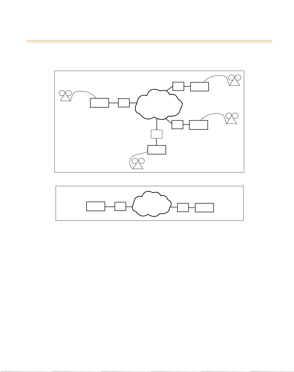
This mapping method is used when it is specified in the configuration wizard that more than two
Discovery IP gateways are in this application (refer to Figure 1).
212
Area Code
770
Area Code
602
Area Code
KSU
IP
Internet
IP
KSU
512
Area Code
IP
IP
KSU
KSU
Multiple Routing Diagram
KSU
IP
Internet
IP
KSU
NOMAP Diagram
Figure 1: Internal Multiple Routing (MAP), and Point-to-Point (NOMAP) Diagrams
Point-to-Point (NOMAP) Routing
The AutoDial option enables all calls made through this Discovery IP to bypass any prefix and
authentication dialing and be placed out of the NOMAP-specified destination Discovery IP. The
destination Discovery IP automatically calls the number, or goes off-hook to connect to the
attached phone line(s) or switch. NOMAP routes all calls originating at a Discovery IP point-topoint to the Discovery IP at the configuration-specified IP address. The specified Discovery IP is
the destination Discovery IP for all calls originating from the first Discovery IP.
This method will allow users to access a line or group of lines connected to the Discovery IP and
place a connection to another Discovery IP without dialing any digits. This mapping method is
used when it is specified in the configuration wizard that only two Discovery IP gateways are in
this application (refer to Figure 1).
Page 18

CALL DETAIL RECORDING 2-3
August 1999 Operational Modes
CALL DETAIL RECORDING
Information collected in Call Detail Recording (CDR) includes the user identification number,
number dialed, time of call, duration of call, type of call, IP address of originating Discovery IP,
IP address of destination Discovery IP, and port used on each Discovery IP.
ACCESSING CDR
For internal Gatekeeper/billing, the CDRs are located in the file found in:
directory called bills. The format of a CDR is:
<customer ID+PIN>,<<number dialed>,<<duration of call in seconds>,<<time of
call:yymmddhhnnss>,<<name of originating Discovery IP>,<<port at originating Discovery
IP used>,<<name of destination Discovery IP>,<<port at destination Discovery IP used>
tempest/billing/
Page 19

2-4 CALL DETAIL RECORDING
Operational Modes August 1999
Page 20

3 Prerequisites for Installation
PHYSICAL ENVIRONMENT
Table 1: Physical Environment
Operating Temperature 5 to 45 °C
Operating Temperature Gradient 10 °C/hr maximum
Operating Humidity 20 to 80 %, non-condensing
Input Voltage, AC Power Supply 115 VAC (90-132 Vms) or 230 VAC (180-264 Vms)
Frequency 50-60 Hz
Maximum Input Current 6.0 A (115 Vms, 60 Hz), 3.0 A (230 Vms, 50 Hz)
Protection Overvoltage, overcurrent, short-current
Typical Output Power 250 W
Console and Auxiliary Ports Asynchronous serial, VGA, PS2 keyboard
Internet Access Dedicated internet connection (not DialUp)
Dimensions 3.5 x 19 x 20.7 in.
Wei g h t 25 lb.
NETWORK INFORMATION
The network configurations must be entered into the Discovery IP configuration program in
order for proper communication to occur. The following information is required for Discovery
IP network configuration:
Full hostname of the Discovery IP, including domain name
IP address of the Discovery IP
Subnet mask of the Discovery IP
IP address of the default router/gateway for the Discovery IP
Timezone of the Discovery IP unit
Discovery IP Technical Manual August 1999
Page 21

3-2 PHYSICAL ENVIRONMENT
Prerequisites for Installation August 1999
Firewall Instructions:
The following firewall ports on the router in the network must be open for inbound as well as
outbound connections, if a firewall exists:
Table 2: Firewall Ports
TCP Ports
UDP Ports
22, 23, 77, 111
700, 708, 709, 800, 1551, 1556, 1557, 1667,
1670, 1671, 1672, 5004, 5005, 5010, 5011,
5016, 5017, 5022, 5023, 5028, 5029, 5034,
5035, 5040, 5041, 5046, 5047, 5052, 5053,
5058, 5059, 5064, 5065, 5070, 5071, 5076,
5077, 5082, 5083, 5088, 5089, 5094, 5095,
5100, 5101, 5106, 5107, 5112, 5113, 5118,
5119, 5124, 5125, 5130, 5131, 5136, 5137,
5142, 5143
PHONE LINE TYPE SUPPORTED
Loop start trunk circuits from a key/PBX system may connect to the Discovery IP unit.
OTHER HARDWARE REQUIRED
A Video Graphics Adapter (VGA) monitor and a keyboard (not included with the Discovery IP)
are necessary to configure, operate and monitor the Discovery IP processes. A laptop computer
with hyperterminal (Version 4) may be used to configure the Discovery IP unit.
Page 22
4 Hardware Installation
VAC Switch
X12 DSP Card
Power Cable Connector
LED- Hard Disk
Activity
LED-Power
115
FXS Analog
Voice Card
(ICV-8)
Network Card
Rear View
Serial Port
Power
to Monitor
to PS Keyboard
Reset
Floppy Drive
Not Operational
Front View
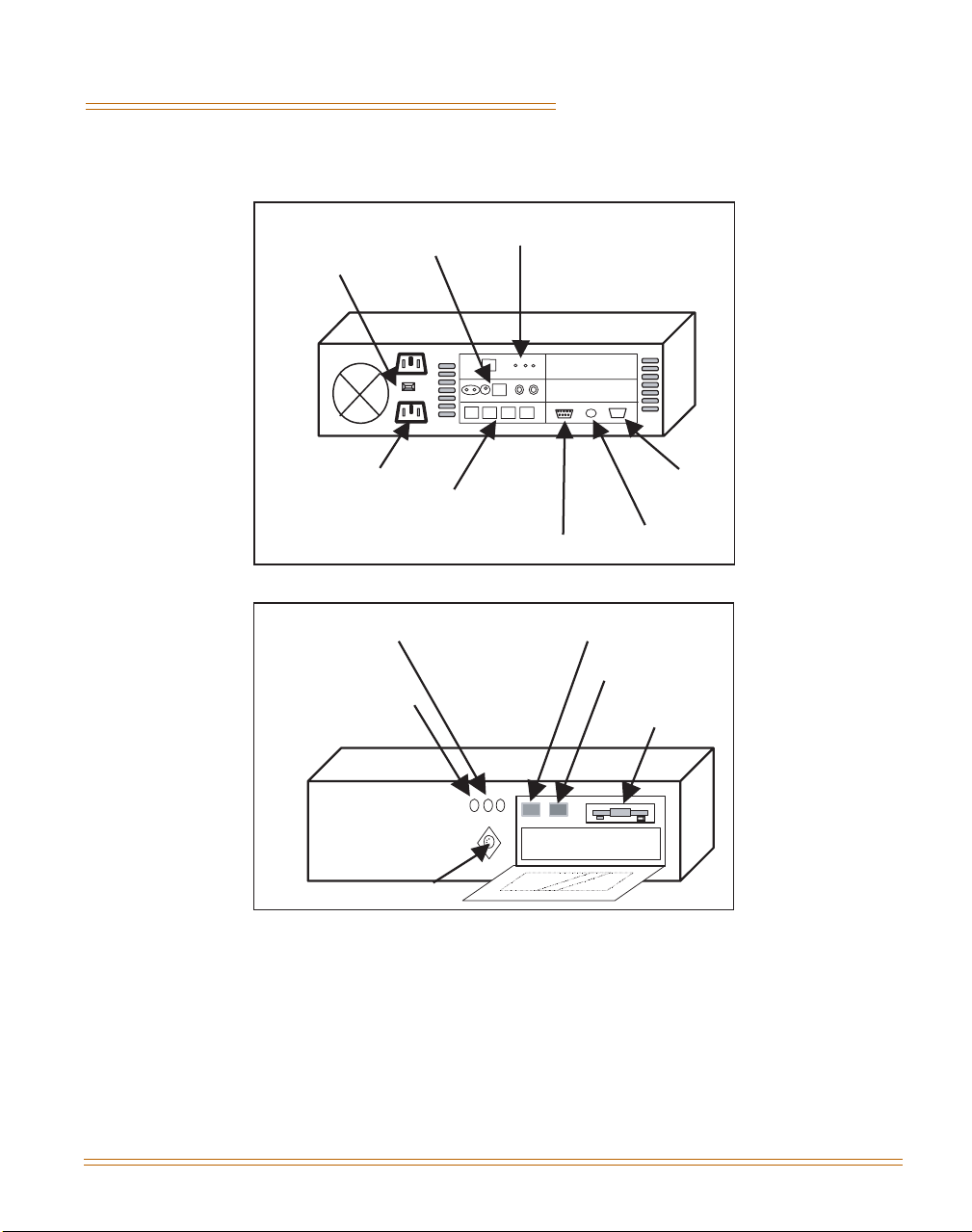
Figure 2: Exterior of the Discovery IP
Discovery IP Technical Manual August 1999
Page 23
4-2
Hardware Installation August 1999
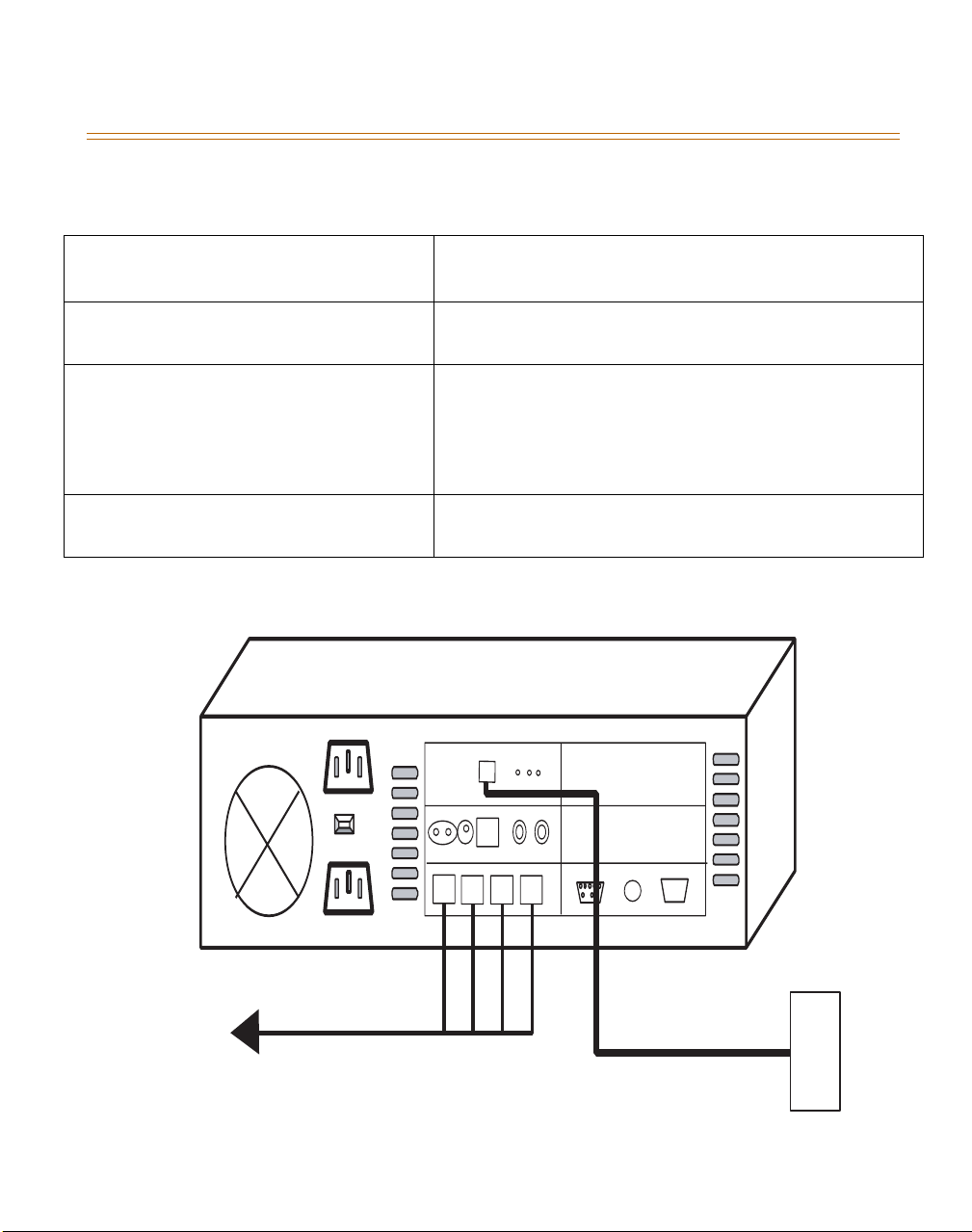
Table 3: Cable Connections
Keyboard(PS2)/Monitor or Serial
Connection (through nullmodem cable)
Power
Phones
LAN/Network
Required for initialization (not included)
115 or 230 VAC - Be sure to set switch (
into wall - surge protection is advised
Two lines per RJ-14 connector. RJ-14 connectors are
ordered from top to bottom. Ports are numbered beginning
00, 01, 02, ..., etc.
Refer to Appendix A for connections to the FXS analog
voice card (ICV-8).
10/100 baseT connection (labeled DATA on rear of
Discovery IP box)
Figure 3 illustrates how the cables should be connected:
do not plug directly
)
To KSU
115
LAN
Figure 3: Hardware Cable Connections
Page 24

4-3
August 1999 Hardware Installation
To turn unit on for the first time, power on the unit from the rear. Machine will boot and show
status messages.
DO NOT turn off the DISCOVERY IP without a proper shutdown
procedure. Doing so may result in damage to the hard disk.
Shutdown Procedure
1. Press
CTRL+ALT+DEL
then wait until all processes have closed completely before
powering down.
OR
2. Type at the command line prompt
shutdown -h now
, then press
only when you can see that all processes have completed shutting down.
ENTER
; power down
Page 25

4-4
Hardware Installation August 1999
Page 26

5 System Configuration
PRIOR TO CONFIGURING THE Discovery IP
The following information is required for the configuration of each
Discovery IP unit. This information should be obtained prior to
installation of the units.
To establish network connection for each Discovery IP machine, you must designate:
Full hostname of the Discovery IP, including domain name
IP address of the Discovery IP
Subnet mask of the Discovery IP
IP address of the default router/gateway for the Discovery IP
Timezone of the Discovery IP
To configure the Discovery IP, you must designate the:
Method of mapping
IP address of the Discovery IP which will serve as the mapping server
IP addresses of machines to be included in mapping scheme
Numeric assignment of each Discovery IP unit
Port number assignments on each Discovery IP
Instructions for Serial Port Connections
Connect your null modem cable to the serial port on the Discovery IP. Connect the other end of
the cable to the machine you will use to configure the Discovery IP.
The Hyperterminal program supplied with Windows can be used to configure the Discovery IP
unit via the serial connection (must be Version 4 to properly function with the Discovery IP).
Be sure to configure your connection for the correct COM port on the machine you're
connecting from. On the machine you are connecting from, configure your connection settings
as follows:
Bits per Second: 9600, Data Bits: 8, Parity: None, Stop Bits: 1, Flow Control: x on/ x off
In Hyperterminal, Configure Key Macros. In case you need to use the Insert and Delete
keys during configuration, perform the following:
1. Go to
Discovery IP Technical Manual August 1999
VIEW>KEY MACROS
[Insert Key] is equivalent to
[Delete Key] is equivalent to
:
<Esc>[2~;
<Esc>[3~;
(i.e. escape key, left bracket, 2, tilda)
(i.e. escape key, left bracket, 3, tilda)
Page 27

5-2 Discovery IP CONFIGURATION WIZARD
System Configuration August 1999
Once connected:
1. Type Root [ENTER]
2. Type dvg-passed [ENTER]
3. Type cd /tempest/dvg [ENTER]
4. Type dvgstatus [ENTER]
5. Type c; and select Configuration Wizard
Discovery IP CONFIGURATION WIZARD
Discovery IP units may be configured through the Configuration Wizard program, which is
accessed through the System Status program always running on each Discovery IP unit.
Upon startup of the Discovery IP, the screen for the System Status program appears.
Upon power-on/startup of the Discovery IP, the below screen displays (Figure 4), then:
1. Type C to view configuration options.
Discovery IP, Vodavi Communications Systems, Inc.
System Status 1.13 - discovery1
ARROWS-move cursor ENTER-configure ESC-quit C-configure
SHIFT+1-one column SHIFT+2-two columns SHIFT+3-three columns P-processes
Figure 4: System Status Main Screen (Startup)
2. Select Configuration Wizard using the arrow keys. Press
ENTER
(as shown in Figure 5).
Page 28

Discovery IP CONFIGURATION WIZARD 5-3
August 1999 System Configuration
Discovery IP, Vodavi Communications Systems, Inc.
System Status 1.13 - discovery1
System Configuration
Configuration Wizard
Routing Manager
Network Configuration
Save Process State
Auto-Save State: On
ARROWS-move cursor ENTER-configure ESC-quit C-Configure
SHIFT+1-one column SHIFT+2-two columns SHIFT+3-three columns P-processes
Figure 5: Configuration Main Screen
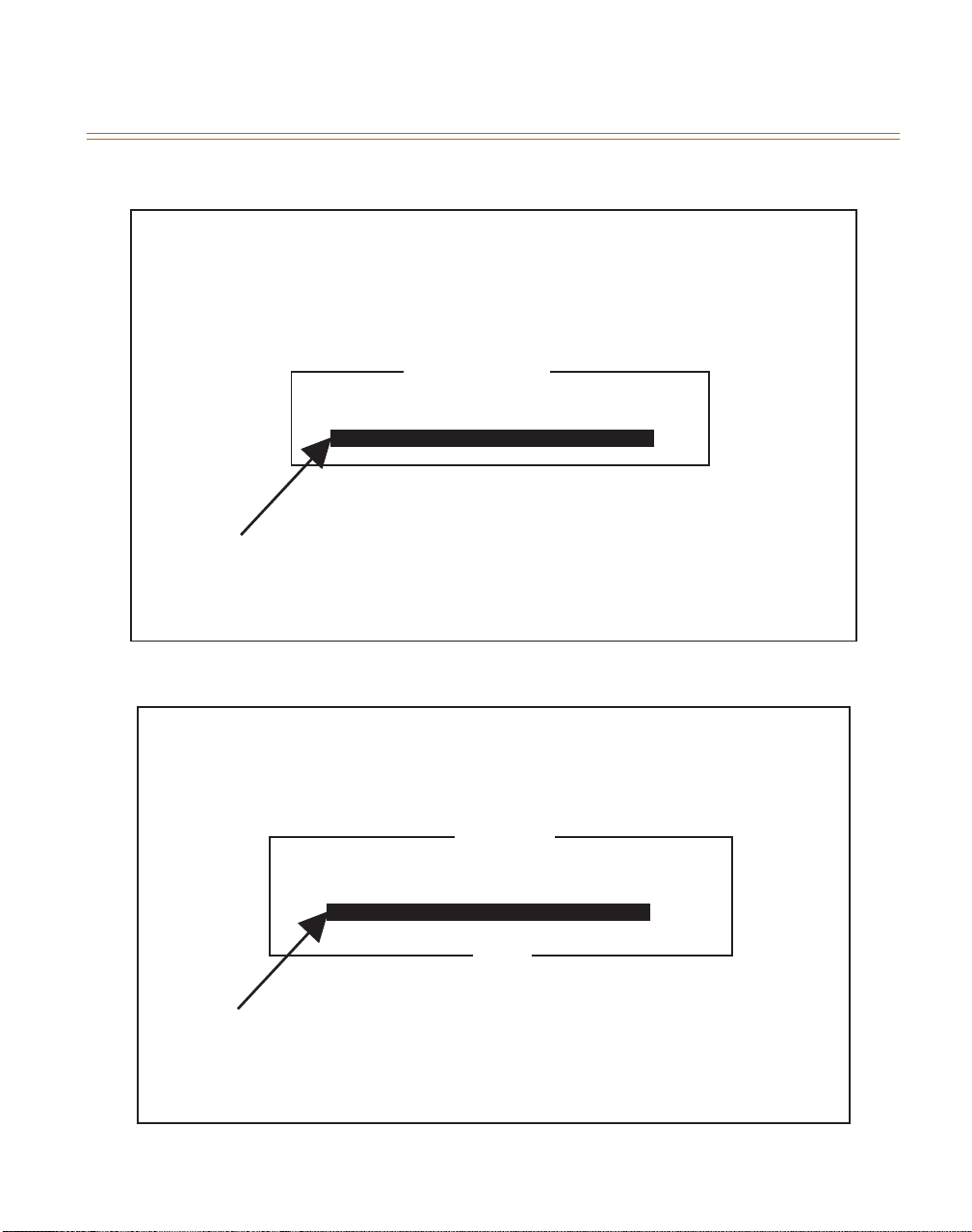
3. Enter the domain name of the Discovery IP unit as shown in Figure 6.
4. Next, enter the IP address of this Discovery IP unit (Figure 7).
Page 29
5-4 Discovery IP CONFIGURATION WIZARD
System Configuration August 1999
Discovery IP
Vodavi Communications Systems, Inc.
Configuration Wizard V1.05
Machine Name
What is the full domain name of this machine?
Enter Domain name here
TAB - Toggle Back Button ENTER - Accept ESC - Abort
Figure 6: Configuration Wizard—Machine Name
Discovery IP
Vodavi Communications Systems, Inc.
Configuration Wizard V1.05
IP Address
What is the IP address of this machine?
Back
Enter IP Address here
TAB - Toggle Back Button ENTER - Accept ESC - Abort
Figure 7: Network Setup—IP Address
Page 30
Discovery IP CONFIGURATION WIZARD 5-5
August 1999 System Configuration
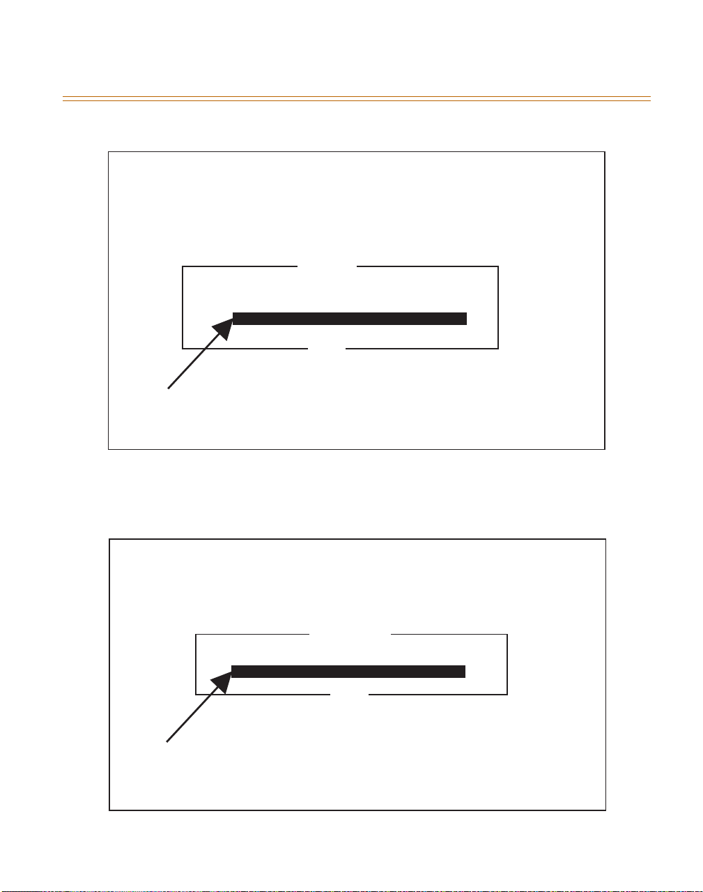
5. Enter the Subnet Mask IP Address, as prompted by the screen shown in Figure 8.
Discovery IP
Vodavi Communications Systems, Inc.
Configuration Wizard V1.05
Net Mask
W
hat is the Net Mask of this machine?
Back
Enter Net Mask here
TAB - Toggle Back Button ENTER - Accept ESC - Abort
Figure 8: Network Setup—Subnet Mask
6. Enter the address of the IP gateway for this network (Figure 9).
Discovery IP
Vodavi Communications Systems, Inc.
Configuration Wizard V1.05
Net Gateway
What is the Gateway of this network?
Back
Enter Gateway here
TAB - Toggle Back Button ENTER - Accept ESC - Abort
Figure 9: Network Setup—IP Gateway
Page 31

5-6 Discovery IP CONFIGURATION WIZARD
System Configuration August 1999
7. Select the appropriate time zone for this Discovery IP unit (Figure 10).
TAB - Toggle Back Button
Figure 10: Timezone Setup
Time Zone
-12:00 Kwajalein
-11:00 Pacific/Samoa
-10:00 US/Hawaii
-9:00 US/Alaska
-8:00 US/Pacific
-7:00 US/Mountain
-6:00 US/Central
-5:00 US/Eastern
-4:00 Canada/Atlantic
-1:00 Atlantic/Cape_Verde
GMT Europe/London
+1:00 Europe/Berlin
+2:00 Europe/Athens
+3:00 Europe/Moscow
+4:00 Asia/Muscat
+5:00 Asia/Karachi
+6:00 Asia/Dacca
+7:00 Asia/Bangkok
+8:00 Asia/Hong_Kong
+9:00 Asia/Tokyo
+10:00 Australia/Sydney
+12:00 Pacific /Fiji
Back
Page 32
Discovery IP CONFIGURATION WIZARD 5-7
August 1999 System Configuration
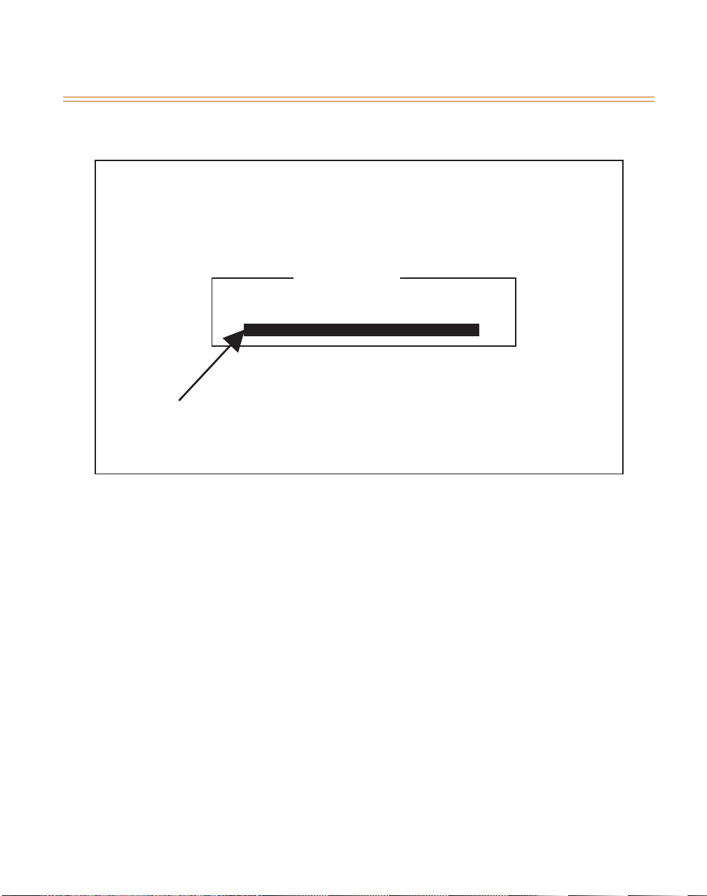
8. Enter the current Date and Time to set the Discovery IP System Clock (refer to Figure 11).
Discovery IP
Vodavi Communications Systems, Inc.
Configuration Wizard V1.05
Set System Clock
Enter the current Date and Time in the following format:
MM/DD/YYYY HH:MM:SS (HH=0-23)
Enter Date and Time here
TAB - Toggle Back Button ENTER - Accept ESC - Abort
Figure 11: System Clock Setup
The routing method of calls is determined by whether two VOIP gateways or more exist in this
Discovery IP application. When NO is selected, all calls originating at this Discovery IP
machine will be placed directly to the other Discovery IP machine (NOMAP). When YES is
selected, a VoIP Mapping Server that keeps the routing information determines from which
machine each call will be placed.
9. Select the appropriate response when prompted by the screen shown in Figure 12.
Page 33
5-8 Discovery IP CONFIGURATION WIZARD
System Configuration August 1999
Discovery IP
Vodavi Communications Systems, Inc.
Configuration Wizard V1.05
Multiple Gateways
Does this application have more than two VoIP gateways on it?
Yes - There are more than two VoIP gateways in this application
No - There are only two VoIP gateways in this application
Back
TAB - Toggle Back Button ENTER - Accept ESC - Abort
Figure 12: Number Of VOIP Gateways Routing Method)
NOMAP Setup
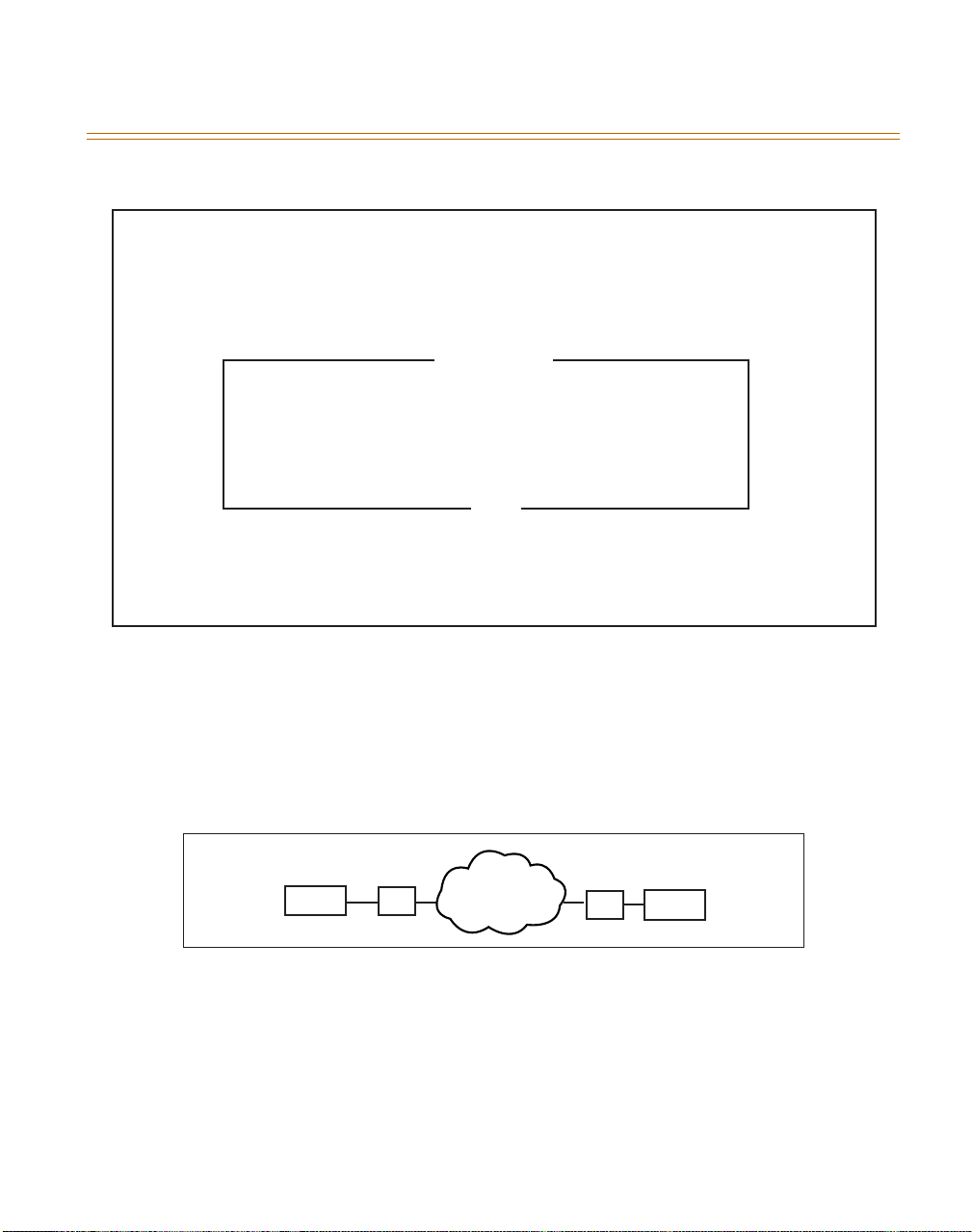
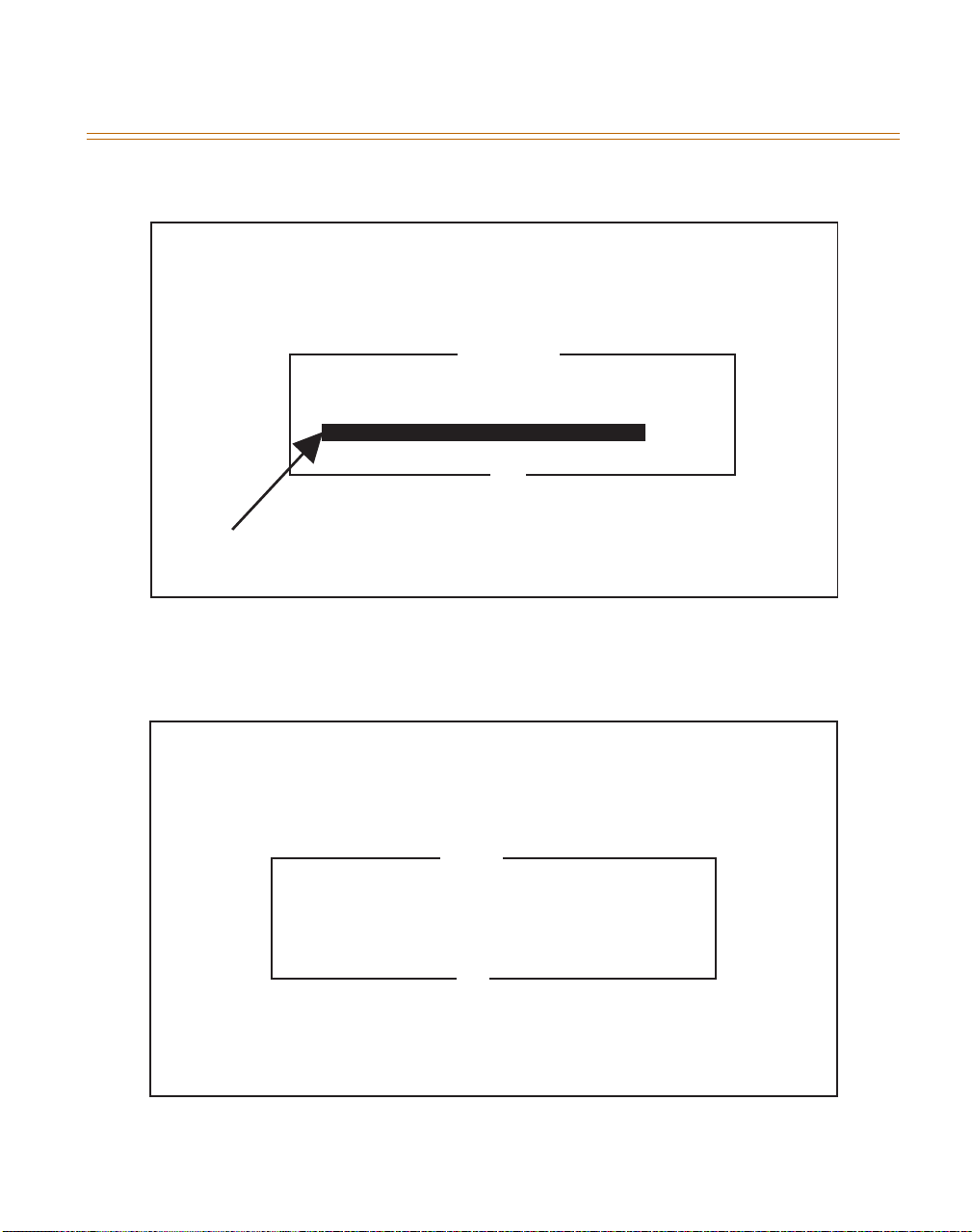
Figure 13 depicts the type of setup that is typical in a NOMAP connection. If only two VOIP
gateways are in this application (i.e., answered NO in Figure 12), the screen that follows asks for
the IP of the other VOIP gateway in this Discovery IP application (Figure 14).
KSU
IP
NOMAP Diagram
Figure 13: NOMAP Diagram
Internet
IP
KSU
Page 34
Discovery IP CONFIGURATION WIZARD 5-9
August 1999 System Configuration
Discovery IP
Vodavi Communications Systems, Inc.
Configuration Wizard V1.05
Other Gateway IP
What is the IP address of the other gateway?
Back
Enter IP Address here
TAB - Toggle Back Button ENTER - Accept ESC - Abort
Figure 14: Routing Setup. With total of two Discovery IP Gateways.
Set up then is complete, as shown in Figure 15:
Discovery IP
Vodavi Communications Systems, Inc.
Configuration Wizard V1.05
File Saved
Configuration file successfully saved
OK
Back
TAB - Toggle Back Button ENTER - Accept ESC - Abort
Figure 15: End of NOMAP Configuration
Page 35

5-10 Discovery IP CONFIGURATION WIZARD
System Configuration August 1999
In order for the new configuration options to take effect, the VOIP services must be restarted.
The wizard asks whether the VOIP services should be restarted immediately (Figure 16).
Discovery IP
Vodavi Communications Systems, Inc.
Configuration Wizard V1.05
(Re)start Services
Would you like to (re)start the VoIP services?
(Services must be (re)started for settings to take effect)
Ye s
No
Back
TAB - Toggle Back Button ENTER - Accept ESC - Abort
Figure 16: ReStart Of VOIP Services For New Settings To Take Effect
After completing the Wizard questions, the following screen prompts, “Would you like to quit
now?” (refer to Figure 17). Selecting YES will result in the appearance of the System Status
screen. Selecting NO will display a previous screen of the Wizard.
Discovery IP
Vodavi Communications Systems, Inc.
Configuration Wizard V1.05
Quit
Quit
Would you like to quit now?
Ye s
No
TAB - Toggle Back Button ENTER - Accept ESC - Abort
Figure 17: End of Configuration Wizard
Page 36
Discovery IP CONFIGURATION WIZARD 5-11
August 1999 System Configuration
Multiple Routing Setup
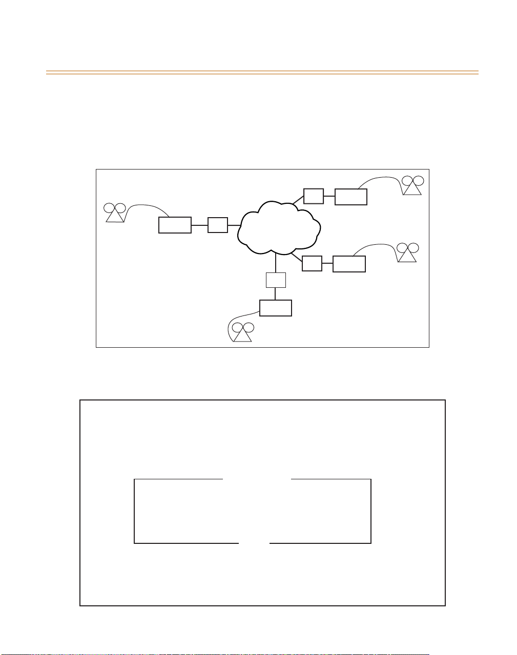
Figure 18 depicts what a typical Multiple Routing connection looks like. If YES was selected in
Figure 12, the following screen (Figure 19) asks if this machine is the VOIP mapping server
(i.e., keeper of routing information). Select
NO in regard to mapping server.
Ye s
. All other IP units in the network must be set to
602
Area Code
KSU
IP
Internet
KSU
512
Area Code
Multiple Routing Diagram
Figure 18: Multiple Routing Setup
Discovery IP
Vodavi Communications Systems, Inc.
Configuration Wizard V1.05
VoIP Mapping Server
Is this machine a VoIP mapping server?
Yes
No
Back
IP
IP
IP
KSU
KSU
212
Area Code
770
Area Code
TAB - Toggle Back Button ENTER - Accept ESC - Abort
Figure 19: Mapping Setup. If total of more than two Discovery IP Gateways.
Page 37
5-12 Discovery IP CONFIGURATION WIZARD
System Configuration August 1999
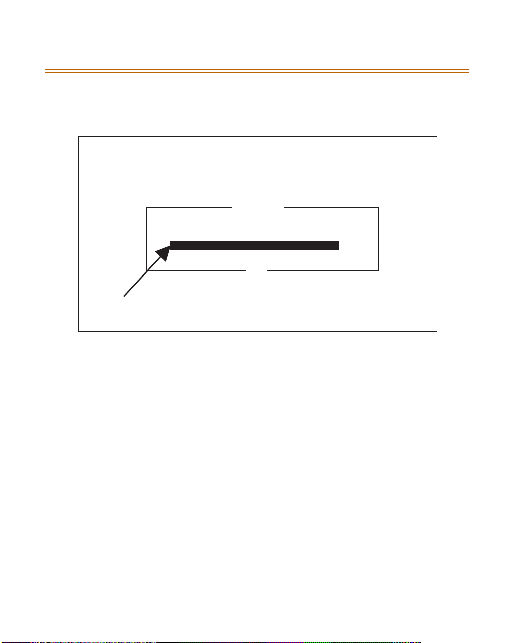
1. Enter the area code or numeric assignment of this Discovery IP unit (Figure 20). This is
the number that will be used to access Gateway #1. The numeric assignment must be 1-9
digits.
Discovery IP
Vodavi Communications Systems, Inc.
Configuration Wizard V1.05
VoIP Gateway ID
What is the Area Code or numeric assignment of VoIP Gateway #1?
(The ID of this machine)
Back
Enter Area code/Numeric Assignment here
TAB - Toggle Back Button ENTER - Accept ESC - Abort
Figure 20: Mapping Setup. If total of more than two Discovery IP Gateways.
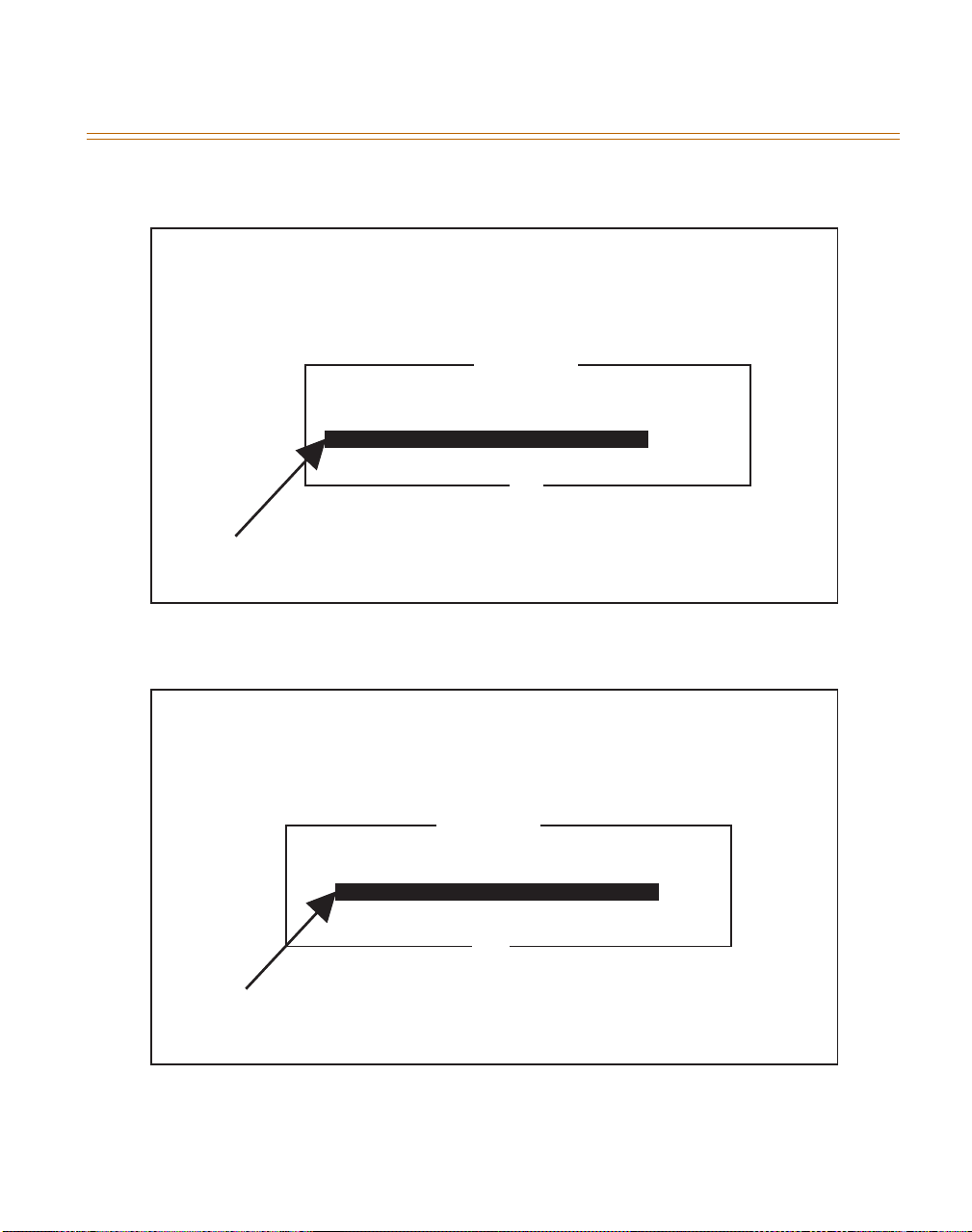
If this Discovery IP is the mapping server, routing must be configured on this unit. The screens
shown in Figure 21 and Figure 22 prompt for each routing data—numeric assignment/area code
and corresponding IP address must be specified for each Discovery IP unit in the network.
Page 38
Discovery IP CONFIGURATION WIZARD 5-13
August 1999 System Configuration
Discovery IP
Vodavi Communications Systems, Inc.
Configuration Wizard V1.05
VoIP Gateway ID
What is the Area Code or numeric assignment of VoIP Gateway #2?
(Enter a blank to stop adding gateways, 20 gateways max)
Back
Enter Area code/Numeric Assignment here
TAB - Toggle Back Button ENTER - Accept ESC - Abort
Figure 21: Mapping Server Setup. If total of more than two Discovery IP Gateways, and Mapping
Server exists on this machine.
Discovery IP
Vodavi Communications Systems, Inc.
Configuration Wizard V1.05
VoIP Gateway IP
What is the IP address of VoIP Gateway #2?
Back
Enter IP Address here
TAB - Toggle Back Button ENTER - Accept ESC - Abort
Figure 22: Mapping Server Setup. If total of more than two Discovery IP Gateways, and mapping
Server Exists on this machine.
Page 39
5-14 Discovery IP CONFIGURATION WIZARD
System Configuration August 1999
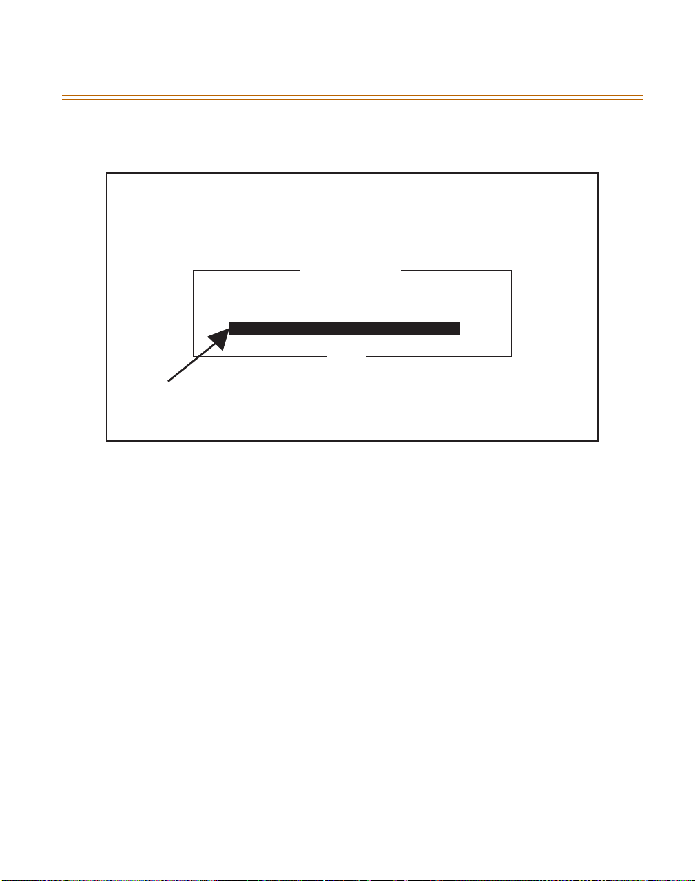
2. To stop adding routes, enter a blank line by pressing
ENTER
when prompted for the
numeric/area code for the next Discovery IP unit (refer to Figure 23).
Discovery IP
Vodavi Communications Systems, Inc.
Configuration Wizard V1.05
VoIP Gateway IP
What is the area code or numeric assignment of VoIP Gateway #7?
(Enter a blank to stop adding gateways, 20 gateways max)
Back
Enter Area Code/Numeric Assignment here
TAB - Toggle Back Button ENTER - Accept ESC - Abort
Figure 23: Mapping Server Setup. When total of more than two Discovery IP Gateways, and Mapping
Server exists on this machine.
If there are more than two VOIP gateways in this Discovery IP application, and this machine is
not the mapping server, then the following screen asks for the IP address of the mapping server
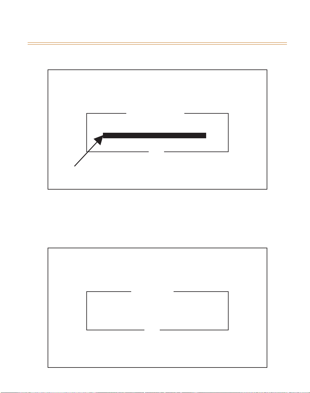
that this Discovery IP unit should use (refer to Figure 24).
Page 40
Discovery IP CONFIGURATION WIZARD 5-15
August 1999 System Configuration
Discovery IP
Vodavi Communications Systems, Inc.
Configuration Wizard V1.05
VoIP Mapping Server
What is IP address of the VoIP mapping server machine?
Back
Enter IP Address here
TAB - Toggle Back Button ENTER - Accept ESC - Abort
Figure 24: Routing Setup. When total of more than two Discovery IP Gateways, and Gateway Server
exists on other machine.
Port number assignment is configured in the following screens. The screen shown in Figure 25
prompts for whether to use a single common number or unique numbers for each of the phone
ports of the Discovery IP unit.
Discovery IP
Vodavi Communications Systems, Inc.
Configuration Wizard V1.05
Hunting Method
Would you like to use a single number for all ports?
Yes - Use a single number for all ports
No - Use a unique number for each port
TAB - Toggle Back Button ENTER - Accept ESC - Abort
Figure 25: Port Number Assignment
Back
Page 41
5-16 Discovery IP CONFIGURATION WIZARD
System Configuration August 1999
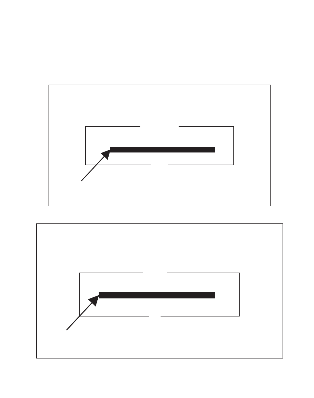
If YES was selected in Figure 25 (i.e., same number for all ports), the wizard asks for the
number to correspond to all ports (Figure 26). If NO was answered in Figure 25, then a port
number must be specified for each port. The screen in Figure 27 appears for each of the ports.
Discovery IP
Vodavi Communications Systems, Inc.
Configuration Wizard V1.05
Port Number
What is the single number for all ports?
Back
Enter Number here
TAB - Toggle Back Button ENTER - Accept ESC - Abort
Figure 26: Port Number Assignment. When all ports have same number.
Discovery IP
Vodavi Communications Systems, Inc.
Configuration Wizard V1.05
Port Number
What is the unique number for the first port?
Back
Enter Number here
TAB - Toggle Back Button ENTER - Accept ESC - Abort
Figure 27: Port Number Assignment. Unique number on each (same prompt on second, third, fourth).
Page 42

Discovery IP CONFIGURATION WIZARD 5-17
August 1999 System Configuration
At the end of the configuration process, the wizard saves the selected options to respective
configuration files, then displays the screen shown in Figure 28.
Discovery IP
Vodavi Communications Systems, Inc.
Configuration Wizard V1.05
File Saved
Configuration file successfully saved
OK
Back
TAB - Toggle Back Button ENTER - Accept ESC - Abort
Figure 28: End of Configuration Process
In order for the new configuration options to take effect, the VOIP services must be restarted.
The wizard asks whether the VOIP services should be restarted immediately (Figure 29).
Discovery IP
Vodavi Communications Systems, Inc.
Configuration Wizard V1.05
(Re)start Services
Would you like to (re)start the VoIP services?
(Services must be (re)started for settings to take effect)
Ye s
No
Back
TAB - Toggle Back Button ENTER - Accept ESC - Abort
Figure 29: ReStart Of VOIP Services For New Settings To Take Effect
Page 43

5-18 MANAGING Discovery IP CONFIGURATION SETTINGS
System Configuration August 1999
After completing the Wizard questions, the following screen prompts, “Would you like to quit
now?” (refer to Figure 30). Selecting YES will result in the appearance of the System Status
screen. Selecting NO will display a previous screen of the Wizard.
Discovery IP
Vodavi Communications Systems, Inc.
Configuration Wizard V1.05
Quit
Quit
Would you like to quit now?
Ye s
No
TAB - Toggle Back Button ENTER - Accept ESC - Abort
Figure 30: End of Configuration Wizard
MANAGING Discovery IP CONFIGURATION SETTINGS
The configuration interface consists of three steps. The first step includes general Discovery IP
settings. The second step includes specifications of mapping address (and autodial number if
applicable), as well as interface-specific port configuration. The third step involves the user
confirming changes to the configuration, and restarting the Discovery IP machine in order for
the new configuration to take effect. At the end of each step, the user may Restore Defaults
(cancel changes to configuration), or Proceed to the next step (submit the changes), by selecting
the appropriate option.
To view the configuration of each Discovery IP machine:
1. From the System Status screen, type C, then select System Configuration (refer to Figure
31
).
Page 44

MANAGING Discovery IP CONFIGURATION SETTINGS 5-19
August 1999 System Configuration
Discovery IP, Vodavi Communications Systems, Inc.
System Status 1.13 - discovery1
System Configuration
Configuration Wizard
Routing Manager
Network Configuration
Save Process State
Auto-Save State: On
ARROWS - Move cursor ENTER - configure ESC - Quit C - Configure
SHIFT + 1 - One column Shift+2 - Two columns Shift +3 - Three columns P - Processes
Figure 31: System Status Configuration Options Screen
The configuration interface is for displaying and making changes to the current configuration.
To select an item on the main screen, move the cursor using the arrow keys, highlight the
item and press
To enter any changes, select the item in the main screen, then type or select the appropriate
setting; press
To go back to a previous screen, press
ENTER
ENTER
.
.
TAB
, then press
ENTER
.
Page 45

5-20 MANAGING Discovery IP CONFIGURATION SETTINGS
System Configuration August 1999
Configuration Step 1 — General Discovery IP Setup
The settings you can edit in Configuration include the following (refer to Figure 32 and 33):
Discovery IP Configuration Step #1 (p1 of 3)
Vodavi Communications Systems, Inc.
Discovery IP Configuration Step #1
Auto Start on Boot: [Yes]
My name: sample1_
Telephone Interface: [Discovery IP Line Cards]
Number of Lines: [4]
Encoding: [Mu Law]
Frames Per Packet: [3]
Gatekeeper: [NOMAP]
Volume: [0]
Local Prefix: [770]
Auto Dial: [Yes]
Account Status Message: [No]
Arrow keys: Up and Down to move. Right to follow a link; Left to go back.
H)elp O)ptions P)rint G)o M)ain screen Q)uit /=search [delete]=history list
Figure 32: Discovery IP Configuration—Step 1
Auto Start on Boot:
Yes or No options. Yes indicates that software should run
automatically upon startup/reboot of the Discovery IP machine.
My Name:
Enter full machine name (or domain name). Maximum length is 30
characters, no spaces.
Telephone Interface type:
Discovery IP Line Cards. Or select appropriate interface from
the list available when this field is clicked-on.
Encoding:
Number of Lines:
Mu-law or A-law. Select appropriate encoding for your configuration.
Enter the number of telephone lines connected to the Discovery IP
machine.
Frames per packet:
Controls quality of speech transmission for varying qualities of
network connections. As the quality of the line deteriorates, the number of frames per
packet should be increased. Enter values ranging from 1 through 8, or enter 0 to select the
default value of 3.
Gatekeeper:
Volu me:
Select the desired method of routing calls originating at this Discovery IP.
Refers to default initial volume upon connection of call. Unless your
Page 46

MANAGING Discovery IP CONFIGURATION SETTINGS 5-21
August 1999 System Configuration
Discovery IP unit is situated on the trunk side of a telco switch, this setting should be set
to Default (by entering nothing). If there is a need to adjust the default voice volume
through the Discovery IP (if situated on trunk side), try setting it to 0 first.
Discovery IP is set to 0 from the factory. If the Discovery IP unit is initialized, or the
software is reloaded, this setting should be changed back to 0.
Local prefix:
Enter local area code.
Autodial:
Valid only if NOMAP was selected as
Gateway type. The autodial number is the number that should automatically be dialed out
of the destination Discovery IP.
Account Status Message:
When enabled (only if AMAS is used) callers into this
Discovery IP will hear a recording (phone bank) detailing the amount of time remaining
before their balance runs out, a restricted period approaching, or when a maximum length
of call is reached.
Discovery IP Configuration Step #1 (p2 of 3)
Vodavi Communications Systems, Inc.
Fax Mode: [Disabled]
Fax Prelode: [32]
Require Authorization: [No]
Authorizion Digits: [14]
Unknown entries and comments:
(Checkbox Field) Use right-arrow or <return> to toggle.
Arrow keys: Up and Down to move. Right to follow a link; Left to go back.
H)elp O)ptions P)rint G)o M)ain screen Q)uit /=search [delete]=history list
Figure 33: Discovery IP Configuration—Step 1 (continued)
Fax Mode:
Select Disabled or G711 (T38 is not yet available with
Discovery IP
software
release 2.28). When a Discovery IP is in Disabled mode, faxes attempted to be sent
through it (as either origination or destination) will fail. In G711 mode, codec for that port
will switch to G711 for the duration of a call detected to be a fax.
Fax preload:
Enter the number of buffers that should smooth the transition of the
outbound queue between voice-transmission mode and fax mode. Enter values ranging
from 1 through 32, or enter 0 to select the default value of 20.
Page 47

5-22 MANAGING Discovery IP CONFIGURATION SETTINGS
System Configuration August 1999
Require Authorization:
gateway types. With AMAS as gateway, this setting must be
Available for use with NOMAP and Gatekeeper/Billing
Ye s.
When used with
NOMAP server type, setting Use Authentication to No will cause the 000.voc voice file
(prompt for entering ID code) to be skipped so that only prompt is 043.voc message (Enter
the number you’d like to dial). No authentication occurs whether the caller is prompted for
the ID code or not.
Authorization digits:
Select the expected length of subscriber ID/PIN code (final four
digits are always taken as the PIN).
Unknown entries and comments:
This section lists the items found in the existing
configuration file, unrecognized by the configuration program. These may include extra
settings provided by Vodavi technical support personnel. The text appearing in this section
may be edited through this configuration program.
Concluding Step 1 of Configuration
Following input of all configuration changes, you can either (refer to Figure 34):
Discovery IP Configuration Step #1 (p3 of 3)
Vodavi Communications Systems, Inc.
Restore Defaults Proceed
(Form submit button) Use right-arrow or <return> to submit.
Arrow keys: Up and Down to move. Right to follow a link; Left to go back.
H)elp O)ptions P)rint G)o M)ain screen Q)uit /=search [delete]=history list
Figure 34: Discovery IP Configuration—Step 1 (continued)
1. Cancel out of the configuration program (cancel any changes made to the configuration),
by selecting
Restore Defaults
at the bottom of the Step 1 Configuration screen.
OR
Page 48

MANAGING Discovery IP CONFIGURATION SETTINGS 5-23
August 1999 System Configuration
2. Continue with changes to the configuration by selecting Proceed at the bottom of the
Step 1 Configuration screen. In this case the setup will continue onto the second step Mapping Address specifications and interface-specific port configuration.
Configuration Step 2 — Mapping Address Specifications
The settings you can edit in this part of the Discovery IP Configuration include the following
(refer to Figure 35):
Discovery IP Configuration Step #2 (p1 of 2)
Vodavi Communications Systems, Inc.
Auto Dial number:
IP Address to sent calls to: XXX.XXX.XXX.X
CAPTION: Line Configuration
Port 0 [FXO] No outbound: [ ] Dial Prefix:
Port 1 [FXO] No outbound: [ ] Dial Prefix:
Port 2 [FXO] No outbound: [ ] Dial Prefix:
Port 3 [FXO] No outbound: [ ] Dial Prefix:
Port 4 [FXO] No outbound: [ ] Dial Prefix:
(Text entry field) Enter text. Use UP or DOWN arrows or tab to move off.
Enter text into the field by typing on the keyboard
Ctrl-U to delete all text in field, [Backspace] to delete a character
Figure 35: Discovery IP Configuration—Step 2
Autodial
: Enter the number which will automatically be dialed for calls mapped to this IP
location. Not specifying an autodial number causes the destination Discovery IP phone
line to go offhook (FXS line at destination Discovery IP will ring).
IP Address to send calls to:
When NOMAP is selected as the gateway type, this setting
specifies which Discovery IP should be the destination box for calls originating at this
Discovery IP.
Gatekeeper IP Address:
This address specifies the location of the Gatekeeper and billing
services when the gatekeeper is the selected gateway type.
Line Configuration:
Depending on the interface type specified in Step 1, the following
needs to be specified for each port on the Discovery IP system.
Each port may be configured to not place outbound calls (accept only incoming calls)
Page 49

5-24 MANAGING Discovery IP CONFIGURATION SETTINGS
System Configuration August 1999
through the No Outbound setting. Each port also may have a dialing prefix associated
with it to precede digits dialed for an outbound call; if port is FXS type, telephone
number associated with that port should be entered into the Dial Prefix field.
All ports existing on the Discovery IP must be configured even if the port is inactive.
Correct configuration of ports is required for proper functioning of
Discovery IP.
Completing Step 2 of Configuration
Once all settings have been entered (refer to Figure 36), the new configuration can be saved by
selecting
Save New Configuration
Discovery IP Configuration Step #2 (p2 of 2)
Port 22 [FXO] No outbound: [ ] Dial Prefix:
Restore Defaults Save New Configuration
from the bottom of the screen, and pressing
Vodavi Communications Systems, Inc.
ENTER
.
(Form submit button) Use right-arrow or <return> to submit ('x' for no cache).
Enter text into the field by typing on the keyboard
Ctrl-U to delete all text in field, [Backspace] to delete a character
Figure 36: Discovery IP Configuration—Step 2 (continued)
Page 50

MANAGING CONFIGURATION THROUGH THE WEB INTERFACE 5-25
August 1999 System Configuration
Configuration Step 3 — Configuration Confirmation
Step 3 of Discovery IP configuration confirms the new configuration has been saved and
instructs the user to restart the Discovery IP machine. At this point, you can quit out of the
configuration program (type Q) or return to a previous step (refer to Figure 37).
Discovery IP Configuration Step #3
Vodavi Communications Systems, Inc.
Discovery IP Updated
Restart to enable new configuration
Type Q to exit.
Are you sure you want to quit? [Y]
Arrow keys: Up and Down to move. Right to follow a link; Left to go back.
H)elp O)ptions P)rint G)o M)ain screen Q)uit /=search [delete]=history list
Figure 37: Discovery IP New Configuration Confirmation
MANAGING CONFIGURATION THROUGH THE WEB INTERFACE
As an alternative, Discovery IP may be configured, monitored, software started/stopped, and the
machine rebooted through a web interface.
To access the web interface:
1. Direct your browser to the name or IP address of the appropriate Discovery IP.
2. Log in as user= dvg, password = dvg-passed.
Page 51
5-26 MANAGING CONFIGURATION THROUGH THE WEB INTERFACE
System Configuration August 1999
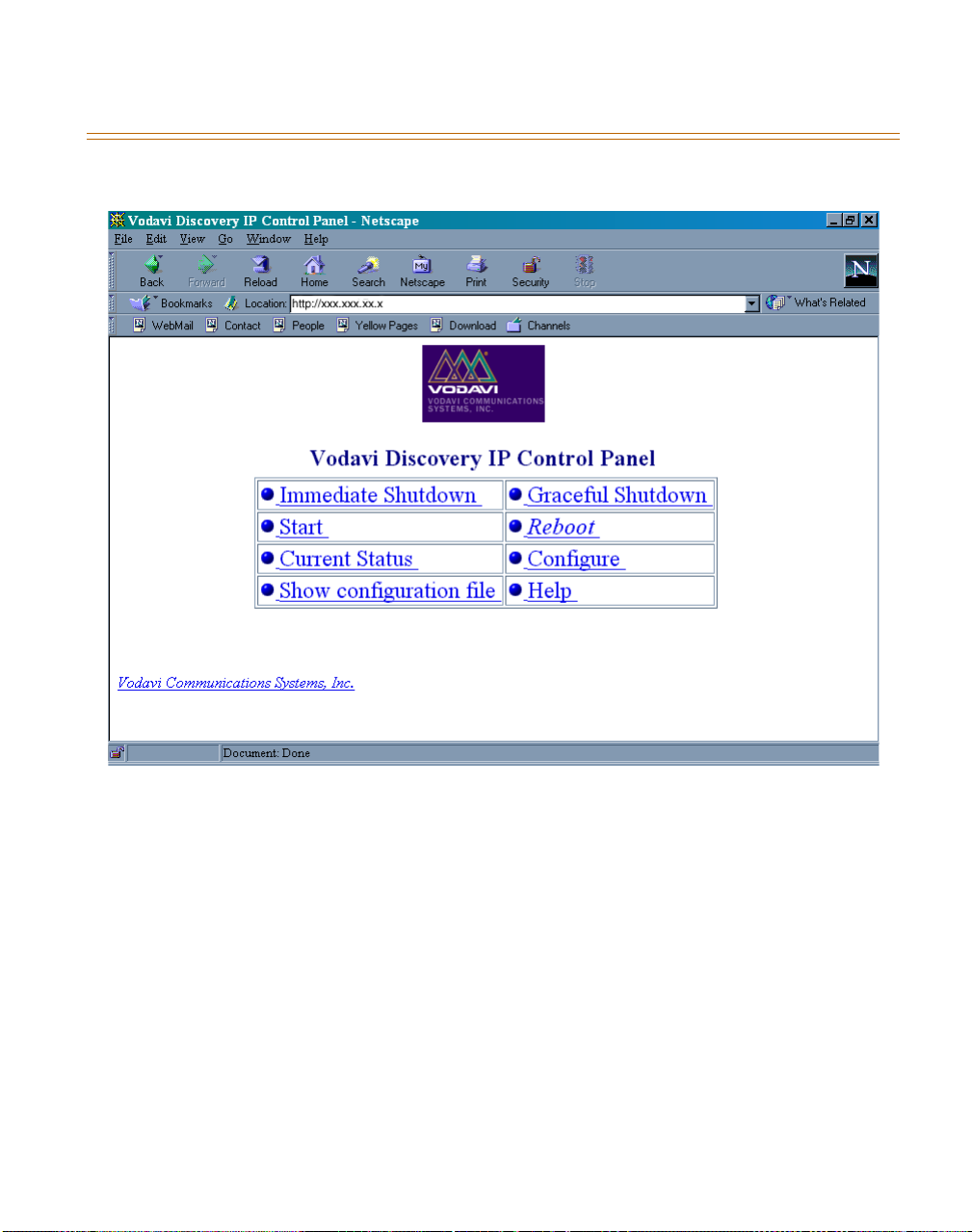
3. The main screen is the first screen seen as in Figure 38, the Control Panel:
Figure 38: Control Panel of Web Interface
Page 52
MANAGING CONFIGURATION THROUGH THE WEB INTERFACE 5-27
August 1999 System Configuration
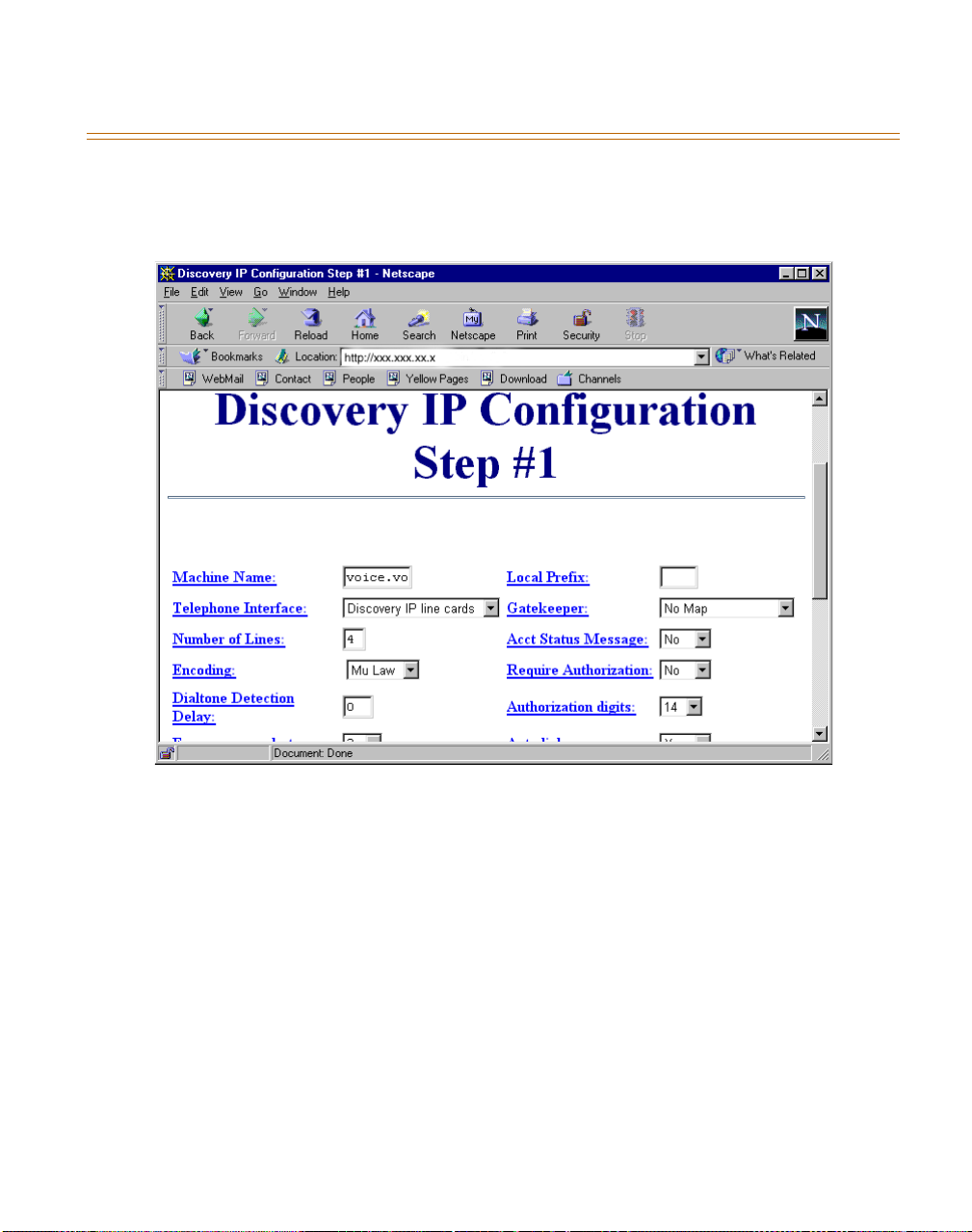
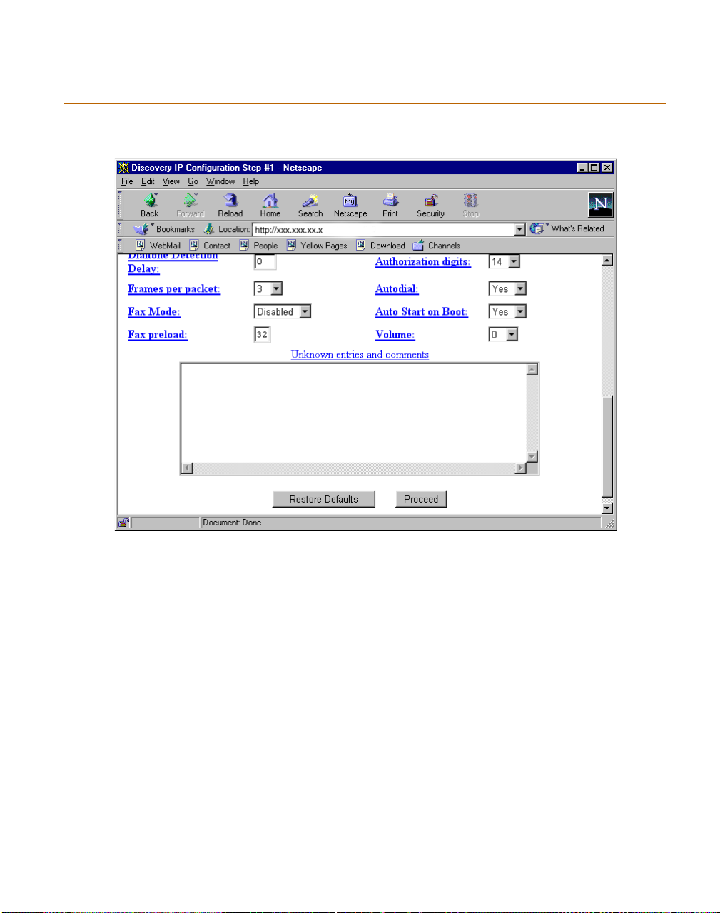
To configure Discovery IP settings, select Configure from the control panel. The screens
containing many of the same settings as described in Figure 32, Discovery IP Configuration—
Step 1, are displayed in Figure 39 and 40:
Figure 39: Discovery IP Configuration Through Web Interface
Page 53
5-28 MANAGING CONFIGURATION THROUGH THE WEB INTERFACE
System Configuration August 1999
Figure 40: Discovery IP Configuration Through Web Interface (continued)
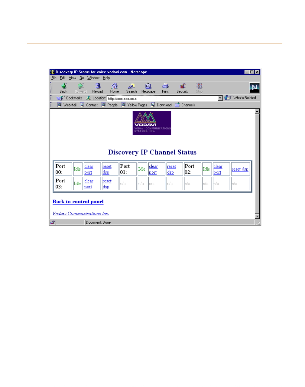
Current port status may be monitored by selecting Current Status from the Control Panel. the
screen that displays enables the resetting of each port (clear port) as well as resetting each port’s
DSP (reset DSP). Figure 41 displays this screen:
Page 54
MANAGING CONFIGURATION THROUGH THE WEB INTERFACE 5-29
August 1999 System Configuration
Figure 41: Port Status Monitoring Through Web Interface
Page 55

5-30 MANAGING CONFIGURATION THROUGH THE WEB INTERFACE
System Configuration August 1999
Page 56

6 System Operation
THE RUNNING PROGRAMS
Programs Which Must be Run for Each Configuration
View the started/stopped status of the required running programs by pressing P (for “processes”)
in the System Status screen. The screen shown in Figure 42 displays these programs.
When choosing to stop
when all lines are onhook (Graceful Shutdown –YES) or to stop
immediately (Graceful Shutdown – NO). In the case that a Graceful
Shutdown is requested, all onhook phone lines are made
unavailable, and the remaining offhook lines become unavailable
as they go onhook.
Discovery IP, Vodavi Communications Systems, Inc.
Process Status Description
dvg Running dvg
vgate Stopped
billing Stopped
, specify whether to stop running only
dvg
System Status 1.13 - discovery1
ARROWS - move cursor ENTER - start/stop ESC - quit C - Configure
SHIFT+1 - one column SHIFT+2 - two columns SHIFT+3 - three columns P - processes
Figure 42: List of Running Programs as Seen in System Status Screen
Discovery IP Technical Manual August 1999
Page 57
6-2 MONITORING Discovery IP ACTIVITY
System Operation August 1999
Locations of Running Programs
Table 9: Locations of Running Programs
Program Location
dvg
vgate
Whenever changing the configuration of any running
/tempest/dvg/
/tempest/gatekeeper/
component, the respective program must be stopped and
restarted in order for the changes to take effect.
Do not run additional copies of a program that is already
running. Doing so will cause problems with the original
running program.
MONITORING Discovery IP ACTIVITY
View the real-time status of each port of a Discovery IP (each port configured using
using the system status screen, as illustrated in Figure 43.
A virtual session cannot be run on a serial connection (laptop
computer).
You may choose to display the information in single column (press
(press
SHIFT+2
), or three column format (press
SHIFT+3
), depending on the size of your
SHIFT+1
), two column
screen and number of ports you wish to view. Figure 43 shows the two-column view of port
statuses. The following (Table 10) lists status messages that are displayed for each port:
dvgconfig
)
Page 58

MONITORING Discovery IP ACTIVITY 6-3
August 1999 System Operation
Discovery IP, Vodavi Communications Systems, Inc.
System Status 1.13 - discovery1
FI DG
00: 000000 ONHK 01: 000000 ONHK
02: 000000 ONHK 03: 000000 ONHK
ARROWS - move cursor ENTER - start/stop ESC - quit C - Configure
SHIFT+1 - one column SHIFT+2 - two columns SHIFT+3 - three columns P - processes
Figure 43: Port Monitoring via
Table 10: Status Messages For Each Port
One-column Two Column Three-column
ONHOOK ONHOOK ONHK
VOICE MAIL VOICEMAIL VMS
RING ON RING ON RGON
OFFHOOK OFFHOOK OFFHH
CONNECTED CONNECTED CONN
RING OFF RING OFF RGOFF
DIALTONE WAIT
(at destination Discovery IP)
GATEKEEPER REMOTE
(communicating with remote gatekeeper)
dvgstatus
DIALTONE DTONE
GATEKEEPER GATE
Page 59
6-4 COLLECTING CALL DETAIL RECORDS
System Operation August 1999
Table 10: Status Messages For Each Port
One-column Two Column Three-column
DVG REMOTE (communicating with
remote Discovery IP)
RECORD FILE (i.e., voice file) RCRD FILE RCRDF
VO I C E P LAY PL AY P L AY
KEY INPUT INPUT INPUT
DVG DVG
The number of calls placed through each port is displayed preceding the status of the port. Use
arrow keys to move between ports, press
ENTER
while a selected port is highlighted to view
the long-version status information for that port.
dvgstatus
The
display does not reflect the actual connection/billing
time; it reflects the connection time since dvgstatus has been
viewing the ports (it also resets when the screen is refreshed).
The top right of the screen lists the programs which are running:
D
for
G
for
(executable)
dvg
vgate
COLLECTING CALL DETAIL RECORDS
Call Detail Records (CDR) can only be collected when using Internal Gatekeeper/Billing Server
or System State Server for authentication and mapping.
For the Internal Gatekeeper/Billing, the CDRs are in the file located in the
directory called
bills
. The format of these CDRs is as follows:
<customer ID+PIN>, <number dialed>, <duration of call in seconds>, <time of call:
yyyymmddhhnnss>, <name of originating Discovery IP>, <port at originating Discovery IP
used>, <name of destination Discovery IP>, <port at destination Discovery IP used>
To access this file, type
To view the file, type
To copy or move the file to a floppy disk, type
then type
cp bills /mnt/floppy/ENTER
(respectively). Finish by typing
cd /tempest/billing
less bills
, then press
umount /mnt/floppy
, then press
ENTER
or type
mount /mnt/floppy
mv bills /mnt/floppy
ENTER
.
, then press
When using the System State Server, CDRs are located on the AMAS in the “PrimaryBill” SQL
database, in the table called “Subrecord”. The Tempest Billing Application retrieves the
information in this table and produces bills for the subscriber accounts on the AMAS.
/tempest/billing/
.
, then press
, then press
ENTER
.
ENTER
ENTER
,
Page 60

RECORD A VOICE FILE MESSAGE 6-5
August 1999 System Operation
RECORD A VOICE FILE MESSAGE
The user must repeat the entire below procedure to record each voice file.
1. Call the Discovery IP.
2. When prompted to enter a subscriber ID and PIN, press
3. To record message mmm (refer to Table 11), enter
begin speaking.
Table 11: Voice Files and Messages
Voice File Message
000.voc Welcome to the TEmpest Gateway. Please enter your 14-digit
ID code.
000.gen Welcome. Please enter your 14-digit ID code.
007.voc Please enter your 14-digit ID code.
043.voc Enter the number you’d like to dial, followed by the pound key.
044.voc Please wait while we connect your call.
#.
* * 1mmm#, wait about 3 seconds, then
050.voc You have one minute remaining on this call.
900.voc Your call cannot be connected. Please try again later.
901.voc No funds are available for this card.
902.voc We’re sorry. Your call cannot be completed as dialed. Please
check the number and dial again.
903.voc All circuits are busy. Please try your call again later.
904.voc The phone number you dialed is not enabled for this card.
905.voc This card is currently in use by another caller. Your call cannot
be connected.
4. Hang up (quietly) when finished recording the voice file.
5. Restart the
in to the Discovery IP, press
press
* * 2mmm#.
process in order to hear the recorded files: To listen to message mmm, call
dvg
when prompted to enter a subscriber ID and PIN. Then
#
Voice files are located in the directory called /tempest/dvg/. Each is named mmm.voc (G.723
format).
Page 61

6-6 DOWNLOADING SOFTWARE UPDATES
System Operation August 1999
DOWNLOADING SOFTWARE UPDATES
To download updated versions of Discovery IP software, enter a virtual session
1. Log in as
typing:
cd /root
2. Then type:
Or in a virtual session already in progress, switch to the
root.
(you are automatically in the
updater.
The following screen is displayed (refer to Figure 45):
Vodavi Communications Systems, Inc.
Discovery IP Update Facility V2.31
Discovery IP Updater
Choose an Update Method:
FTP server
Floppy
Local Directory
Discovery IP
<Back>
/root
directory upon logging in).
/root
ALT F3
:
directory by
Figure 45: Updater Main Menu
3. In making selections, use the arrow keys:
or
to move between choices,
↓↓↓↓
↑↑↑↑
←←←←
or
→→→→
implement an action (select, exit or help). [As of software release 2.31V, FTP Server is the
only enabled method of updating.]
to
Page 62
DOWNLOADING SOFTWARE UPDATES 6-7
August 1999 System Operation
Update Using FTP
To update through Vodavi’s ftp site, press ENTER, or to address the updater to a different ftp
site, enter in the appropriate address for that site (refer to Figure 46)
Discovery IP, Vodavi Communications Systems, Inc.
Discovery IP Update Facility V2.31
Discovery IP 2.31 V Updater
What is the full ftp name of your ftp update site:
Enter ftp Site Address here
Figure 46: FPT Server Address
To update via FTP, DNS must be configured in Discovery IP’s
network configuration. Figure 47 shows the screen that is displayed,
listing the available versions to update to. Make your selection.
Page 63

6-8 DOWNLOADING SOFTWARE UPDATES
System Operation August 1999
Discovery IP, Vodavi Communications Systems, Inc.
Discovery IP Update Facility V2.31
Discovery IP 2.31 V Updater
Choose from the following update options for your current version:
2.xx Update current release to 2.xx
Exit Abort Upgrade
<OK> <Cancel>
Figure 47: FTP Update Menu
When the update is complete, the Discovery IP must be power-cycled for the changes to take
effect.
1. Power off by pressing
CTRL+ALT+DEL
then hitting the power switch.
2. Turn-on the machine again.
3. Review and save a new Discovery IP configuration file to include any additional
parameters used with the new version of Discovery IP software.
4. Start all necessary processes as usual.
RESTART/SHUTDOWN OF Discovery IP
To restart a Discovery IP:
1. Press
2. Type at the command line prompt: shutdown –r now, and press
3. The operating system will close open files and reboot.
To shutdown a Discovery IP:
1. Type at the command line prompt: shutdown -h now, then press
CTRL+ALT+DEL
,
OR
ENTER
ENTER
down only when you can see that all processes have completed shutting down.
.
; power
Page 64

DOWNLOADING SOFTWARE UPDATES 6-9
August 1999 System Operation
Failure to properly restart/shutdown the Discovery IP may result in
hard-disk damage, if the buffer is unable to repair itself. If the
system is improperly restarted/shutdown, on startup, the machine
will display the following message:
dev/hda2 was not cleanly unmounted, check forced.
This will verify that the hard drive was not damaged in the improper
restart/shutdown.
Page 65

6-10 DOWNLOADING SOFTWARE UPDATES
System Operation August 1999
Page 66

7 Calling Instructions
ESTABLISHING/MAINTAINING A VoIP CONNECTION
The connection is established as the user accesses a CO line connected to the Discovery IP unit.
CO lines can be accessed using a CO line group access code, off hook preference, or direct
access:
1. A voice message (message 043) prompts for the phone number to be called or caller is
connected directly to another IP unit (NOMAP), followed by a #
enter a
2. What follows depends on whether the caller receives successful authentication.
If mapping route is found and ports are available, a connection is established. The caller
may signal the Discovery IP by entering the following:
✳1
✳2
✳3
✳4
✳7
✳8
#, after 3 seconds, the entry of number to call is assumed to be completed.
:
increase volume
:
decrease volume
increase latency
:
decrease latency
:
disconnect from the Discovery IP
:
anchor connection to Discovery IP so that another call can be made
:
Pressing either #, or ✳ will be heard by the call recipient at the
destination Discovery IP.
. If the caller does not
Discovery IP Technical Manual August 1999
Page 67

7-2 ESTABLISHING/MAINTAINING A VoIP CONNECTION
Calling Instructions August 1999
Page 68
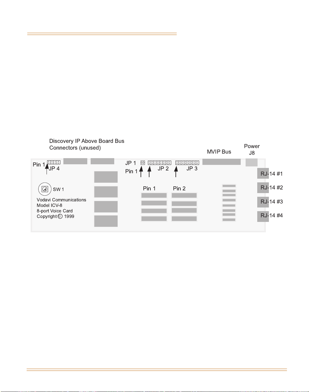
A Interface Card
ICV-8 CARD
ICV-8 Layout
The ICV Board (refer to Figure A1) provides four analog FXS phone connections to the external
world. Two FXS phones can be plugged into each of the four external connectors. The
equipment is identified by a model and serial number printed on the printed circuit board. The
ICV Board mounts in one slot of a PC/AT chassis ISA Bus.
Discovery IP Above Board Bus
Connectors (unused)
Pin 1
JP 4
SW 1
Vodavi Communications
Model ICV-8
8-port Voice Card
Copyright
C
1999
JP 1
Pin 1
Pin 1 Pin 2
MVIP Bus
JP 2 JP 3
Power
J8
RJ-14 #1
RJ-14 #2
RJ-14 #3
RJ-14 #4
Figure A-1: ICV -8 Jumper and Connector Layout
The analog phone lines are connected to the ICV Board by the RJ-14s shown at the right of the
drawing. RJ-14 is the same size and shape as a RJ-11 but four wires are used whereas a RJ-11
supports only two wires. The first line of each ICV Board is the center pair of RJ-14 #1. The
second line is the outer pair of the same RJ-14. Each of the eight lines is numbered
consecutively (refer to Figure A2).
Discovery IP Technical Manual August 1999
Page 69
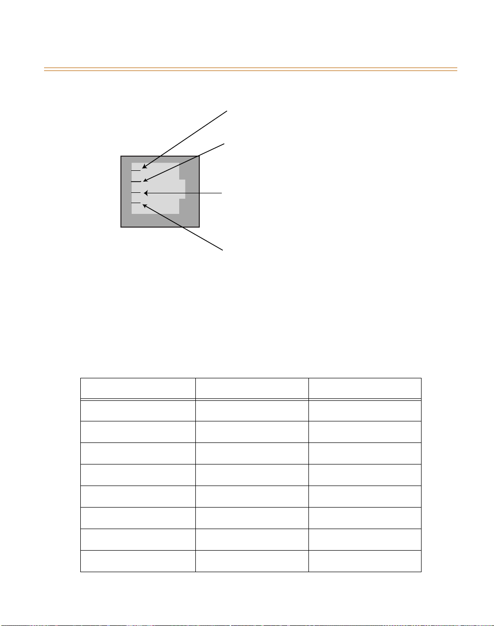
A-2 ICV-8 CARD
Interface Card August 1999
Pin 5 - L2 Ring
Pin 4 - L1 Tip
Pin 3 - L1 Ring
Pin 2 - L2 Tip
Figure A-2: RJ-14 Pinout
Jumper Settings
JP2 and JP3 select one of eight streams of the MVIP bus. JP2 makes the transmit stream
connection, while JP3 makes the corresponding receive connection. These two jumpers are
typically set to the same stream number. One jumper is placed on each block according Table
A1:
Table A-1: JP2 and JP3 MVIP Bus Stream Selection
Position Stream in MVIP Bus Stream in Vodavi ABB
100
211
322
433
5 Not used None
6 Not used None
7 Not used None
8 Not used None
Page 70

B Parts Specifications
NETWORK CONNECTION
10/100BaseT
Data Rate 10 Mbps or 100Mbps
Network Interface Standard IEEE 802.3
Connector RJ45
POWER SUPPLY
Data AC Input 115 ~/230 , 6/3 A 60/50 HzV
Network Interface Standard IEEE 802.3
Approvals UL, CSA, TUV, CE
SBC
Speed supported up to 133 MHz
HARD DISK
Capacity 4.3 Gb
Discovery IP Technical Manual August 1999
Page 71

B-2 NETWORK CONNECTION
Parts Specifications August 1999
Page 72

CGlossary
ABB:
ADPCM:
AIS:
which signals that an upstream failure has occurred.
Above Board Bus
Adaptive Differential Pulse Code Modulation
Alarm Indication Signal, usually all ones—F11111111. Also known as a Blue Alarm
Alarms: Red: refer to Loss of Sync. Yellow: Same as Red, but reported from the other side of
the connection. Blue: refer to AIS. Slip: refer to Slip.
AMI:
the signal alternate between binary positive and binary negative polarity.
ATM:
packet-switching transmission protocol standard. ATM uses short, uniform, 53-byte cells to
divide data into efficient, manageable packets for ultrafast switching through a
high-performance communications network. The 53-byte cells contain 5-byte destination
address headers and 48 data bytes. ATM is the first packet-switched technology designed from
the ground up to support integrated voice, video, and data communication applications. It is
well suited to high-speed WAN transmission bursts. ATM currently accommodates transmission
speeds from 64 Kbps to 622 Mbps. ATM may support gigabit speeds in the future.
B8ZS:
channel line coding option on DS-1 service allows the DS-1 user to obtain greater throughput
and functionality from their DS-1 facilities. The use of B8ZS allows users to transmit data at a
rate of 64 Kbps per DS-0, achieving what is referred to as a clear channel. Applied against all
24 DS-0s on a DS-1, the effective data throughput of the DS-1 facility is increased with B8ZS
from 1.344 Mbps to 1.536 Mbps, a 14% increase in throughput. CSUs with B8ZS support are
required on both ends of the user's circuit.
Alternate Mark Inversion. A line coding format for T-1 lines where the condition of
Asynchronous transfer mode. An international ISDN high-speed, high-volume,
Bipolar with eight zero substitution. A protocol used over T-1 interfaces. Clear
Baud:
be transmitted per second on a circuit. In an average data stream, one baud is roughly equivalent
to one bit per second on a digital transmission circuit.
bps:
Bps:
CCITT:
Consultative Committee on Telephones and Telegraphs). The primary international standards
body for telecommunications. CCITT is an advisory committee established under the United
Nations, within the International Telecommunications Union (ITU), to develop and recommend
communications standards.
Discovery IP Technical Manual August 1999
Baud (older term being replaced by bps). The number of signaling elements that can
Bits per second.
Bytes per second. Each byte contains eight bits.
Comité Consultatif Internationale de Télégraphique et Téléphonique (International
Page 73

C-2
Glossary August 1999
Channel Bank:
associated signaling) into a single T-1 (DS-1) digital circuit.
Cross Point Switch:
electronic patch panel).
CSU:
Responds to Central Office commands. It performs many of the functions that modems do, but
it does not have to convert digital signals to/from analog, since the end device and the
underlying transmission facility are both digital.
D4:
single 193
known as SF, has been superseded by the Extended Super Frame (ESF) format. However,
because ESF is not backward compatible and there continues to be a large installed base of
channel banks and DS-1 multiplexers that are based upon D4, it is still the default private line
formatting technique.
DCE:
An example of DCE is the common modem that connects to voice grade lines of a telephone
network.
DS-0:
channels operating at 64 Mbps.
DS-1:
channels operating at 1.544 Mbps (refer to T-1).
Channel Service Unit; manages digital transmission, monitors signals for problems.
A data transmission (or superframe) format comprised of 12 frames of 192 bits each. A
rd
bit is used for link control and error checking. As an industry standard, D4, also
Data Communications equipment; device designed to connect directly to a network.
Digital Signal Level 0; the designation given to a digital hierarchy of circuits or
Digital Signal Level 1; the designation given to a digital hierarchy of circuits or
A PCM voice frequency terminal that converts analog channels (and
A device that assigns different channels to different ports (an
DSU:
DTE. Usually associated with a CSU, the DSU has a V.35, RS232, RS449, or other interface to
the customer equipment. The DSU is also a multiplexer for FT-1 circuits.
DSX:
DTE:
originate or receive data over a communication channel.
ESF:
standard. ESF is composed of 24 frames of 192 bits each. ESF provides 16 signaling states in
the 193
FDL:
FSYNC:
group of 32 channels
FT-1:
64 Kbps increments from 2-channel 128 Kbps through all 24 channels at 1.544 Mbps.
FXS:
Data Service Unit; a network interface device between the CSU and the customer's
Digital Signal Cross-connect.
Data Terminal Equipment; any form of computer, peripheral or terminal that can
Extended SuperFrame; an enhanced version of D4 formatting, it is the current industry
rd
bit to ensure synchronization, supervisory control, and maintenance capabilities.
Facility Data Link
Frame Sync; is bit-signaling that occurs at the beginning of each frame, or each
Fractional T-1; a service that uses a portion of a 24-channel T-1 circuit. FT-1 allows
Foreign Exchange Station
Page 74

C-3
August 1999 Glossary
ICV:
ISA:
clone computers to connect adapter cards to the motherboard.
LAN:
transmission and a low error rate in connecting computer system and terminal devices within a
department or establishment.
LOS:
Loss of Sync:
also be a good indication that the wiring is not properly completed.
MPP:
MVIP:
computer chassis.
NIU:
Null Modem:
PC:
PCM:
analog signals to a digital format. In telephony, the PCM technique converts analog voice to an
8-bit digital format at an 8 kHz rate, producing an aggregate serial bit stream of 64 kbps.
POTS:
line.
ISA Communications Voice card.
Integrated System Architecture; the standard connector used internally for IBM-PC
Local Area Network; a communications network that provides a high rate of data
Loss of Signal; on a T-1 SmartJack or NIU this LED indicates loss of carrier.
Indicates an improper or no signal coming from the other side. This could
Multi-Protocol Packet Assembler/Disassembler (PAD)
Multi-Vendor Integration Protocol; allows multiplexed digital telephony within a
Network Interface Unit; where a T-1 signal is provided to the customer from the telco.
A device that allows DTE to DTE or DCE to DCE communications.
Personal Computer or Printed Circuit (depending on context).
Pulse Code Modulation; the technique most frequently used to sample and convert
Plain Old Telephone Service; refers to a one-party, no frills business or residential
SF:
Superframe (D4); a data transmission format comprised of 12 frames of 192 bits each. A
single 193
known as SF, has been superseded by the Extended Super Frame (ESF) format.
Slip:
automatically. This can cause a noisy connection. High-speed modems will tend to reduce
throughput or even fail on continued slip conditions. Frequent or repetitive slips can be caused
by improper software settings.
SNA:
protocol.
SNMP:
Task Force, a committee of vendors and academics. SNMP is designed to manage
inter-networked LANs and packet switched networks. It is most commonly employed in TCP/
IP networks.
SMTP:
rd
bit is used for link control and error checking. As an industry standard, D4, also
Synchronization of Clocks on digital channel service failed and recovered
IBM System Network Architecture; mainframe-centric hierarchical communication
Simple Network Management Protocol; recommended by the Internet Engineering
Simple Mail Transfer Protocol; a TCP/IP application utility.
Page 75

C-4
Glossary August 1999
T-1:
USA or at the E1 rate of 2.048 Mbps in Europe.
TCP/IP:
Defense Advanced Research Projects Agency (DARPA) for use in the U.S. Military ARPANET,
now in commercial use. TCP/IP ensures that packets of data are delivered to their destination in
the sequence in which they were transmitted. TCP is the Transport Layer protocol and IP is the
Network Layer protocol in this suite. TCP/IP is also the delivery mechanism for associated
services, including SNMP, SMTP, FTP and Telnet.
Telnet:
X.25:
packet-switched network and the service features available when connected to the network. The
definition describes the characteristics of the Physical, Data Link and Network Layer
Any transmission line or connection operating at the DS-1 rate of 1.544 Mbps in the
Transmission Control Protocol / Internet Protocol; a protocol suite developed by the
A TCP/IP application utility that provides terminal emulation.
A CCITT recommendation that defines the interface between DTE and a
Page 76

D Country Specific Information
UNITED STATES OF AMERICA
FCC Part 15
The components of this equipment have been tested and comply with the limits for a Class A
digital device according to U.S. Code of Federal Regulations, Title 47, FCC Rules and
Regulations Part 15. Operation is subject to the following two conditions:
1. This device may cause harmful interference, and
2. This device must accept any interference received, including interference that may cause
undesired operation.
Discovery IP Technical Manual August 1999
Page 77

D-2 UNITED STATES OF AMERICA
Country Specific Information August 1999
Page 78

E Troubleshooting
Table E-1: Troubleshooting Checklist
Observed Problem Probable Cause Suggested Solution
Calls into the Discovery IP on that
port(s) are unanswered, OR calls are
unable to be placed out of that port(s).
Calls into the Discovery IP on that
port(s) are unanswered, OR calls are
unable to be placed out of that port(s).
Calls into Discovery IP on that port(s)
are unanswered, OR calls are unable to
be placed out of that port(s).
dvg process does not start properly
(stops immediately after you attempt to
start it).
dvg does not run properly or smoothly. Discovery IP
Unable to reach updater ftp site. Network configuration
Log shows segmentation fault while
trying to start up the dvg process.
Phone line not
connected to the port
Bad connector/
connection
Dvgconfig ports not set
up with correct DID/
DOD characteristics.
dvgconfig ports not set
up with correct settings
or in correct quantity
configuration requires
adjustment
is not set up to specify a
DNS server with
reverse-DNS
Did not go through
dvgconfig (saving the
configuration) before
restarting Discovery IP
unit after running
updater
Check connectors and connections.
Replace connectors/cables if
necessary.
Check connectors and connections.
Replace connectors/cables if
necessary.
Check the dvgconfig setup, and if
necessary contact the telephone
company providing the line to check
on type provisioned.
Check port configuration. Any
change while dvg is running require
that dvg is stopped/restarted.
Check all configuration items in
dvgconfig. any changes while dvg is
running require that dvg is stopped/
restarted.
Go through network configuration
process and check that a valid DNS
IP address is specified. Check also
that reverse-DNS exists on that
network connection.
Whenever running updater, run
dvgconfig, set additional
configuration options, save the new
configuration, reboot the Discovery
IP, start the Discvoery IP process
again.
Bad voice quality Network issues: packet
loss
Bad voice quality Network issues: latency,
loss of connection
Discovery IP Technical Manual August 1999
Adjust frames per packet setting in
dvgconfig.
Caller may adjust latency by
entering ✳✳✳✳3 or ✳✳✳✳4
Page 79

E-2
Troubleshooting August 1999
Page 80

INDEX
B
Billing
Call Detail Recording
C
Call Detail Recording 2-3
Collecting
Calling
Instructions
CDR
refer to Call Detail Recording
Circuits
Loop Start Trunk
Configuration
Managing Settings
Port
Port Number
Settings
Setup
System
Web Interface
Wizard
Machine Name 5-4
D
Discovery IP
Billing
Call Detail Recording 2-3, 6-4
Calling 2-1, 2-2, 5-9–5-15, 7-1
Routing 2-1
Configuration 5-2, 5-15–5-18, 5-20, 5-23,
5-24, 6-1
Options 5-19
Web Interface
Wizard
Connections 5-1
Description
Gatekeeper Module
Hardware
6-4
7-1
5-1, 6-1
5-23, 5-24
5-15, 5-16, 5-20
5-18
5-1
5-19
5-3, 5-10, 5-18
5-3, 5-10, 5-18
1-1
4-1, B-1
5-25
3-2
5-18–5-25
5-25
1-2
2-3
Requirements 3-2
Installation 3-1
Requirements 3-1, 3-2
Internet Protocol 5-5, 5-8–5-15
Module
Gatekeeper 1-2
Monitoring 6-2
2-1, 3-1, 3-2
Network
Operation 6-1
Reboot
Setup
Setup/Configuration
Software
System
Troubleshooting E-1
G
Gatekeeper Module 1-2
Glossary
I
Installation
Hardware
Prerequisites 3-1
Requirements
Interface Card
Internet Protocol
Gateway
Telephony Standards
IP Address
IP Telephony
Applications 1-3
Components
6-8
5-4–5-15
Updates 6-6, 6-7
Configuration 5-1
C-1
Requirements 3-2
5-4
1-2
4-1
3-1
A-1
1-1
5-5, 5-8–5-15
1-1
5-1
1-2
Discovery IP Technical Manual
August 1999
Page 81

x Index
Discovery IP Technical Manual August 1999
L
LAN
refer to Local Area Network
Local Area Network (LAN)
M
Microsoft Corporation
1-2
5-5
6-2
3-2
1-3
2-2
2-1
Windows NT
Monitoring
N
Network 3-1
Applications
Firewall
Multiple Unit Routing
Setup
IP Address 5-4
Network Components 1-2
NOMAP
refer to Point-to-Point Routing
O
Operation 6-1
P
Parts Specifications B-1
Point-to-Point Routing
Port
Serial Port Connections
1-1
5-1
Product Description
Product Overview
Public Switched Telephone Network
R
Reports
Call Detail Recording
S
Software
5-6
1-2
1-2
6-6, 6-7
Updates
T
Telephone Network
Public Switched (PSTN)
Telephony
Standards
Timezone
Setup
Troubleshooting
V
Voice Message 6-5
Voice Packetizing
G.711
G.723
W
WAN
refer to Wide Area Network
Wide Area Network
1-2
E-1
1-1
1-2
1-1
2-3, 6-4
1-1
1-1
Page 82

www.vodavi.com
©1999 Vodavi Technology ,Inc.
VODAVI is a registered trademark ofVodavi Technology, Inc.
9860-00 8/99
we’re talking
technology
 Loading...