

Page 1

XMA1200 - QUICK INSTALL GUIDE
FULL ARTICULATING MOUNT
UNIVERSAL FOR 40” - 60” TVS UP TO 120 LBS
Page 2
IMPORTANT SAFETY INFORMATION
Read the Important Safety Information on this page before installing or using this mounting system.
Always follow the instructions in this Quick Install Guide. VIZIO is not liable for damage or injury caused by incorrect
mounting, assembly, or use.
This mount fits most screens from 40” to 60”.
This mounting system supports a maximum weight of 120 lbs and a maximum screen size of 60”. Attaching a screen
that is larger or heavier than specified above may result in personal injury or damage to your TV.
If you have any doubts about the ability of the wall to support the mounting system or your TV, do not install the
mounting system. Contact a qualified contractor.
Only attach this mount system to vertical walls as instructed in this Quick Install Guide.
Keep all contents of this box away from small children. This product contains small items that could be a choking
hazard if swallowed.
This mounting system is for indoor use only.
Page 3
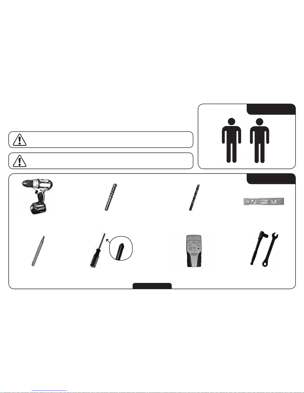
STEP 1 - BEFORE YOU BEGIN
YOU WILL NEED
Power Drill 1/2” (12.5mm) Concrete Drill Bit 7/32” (5.5mm) Drill Bit
Pencil Electronic Stud FinderPhillips-head Screwdriver Assorted Wrenches
Level
Before you begin the installation, ensure you have all of the items listed on this page. Do
not begin the installation unless you have all of the following items.
Mounting a TV requires lifting. To make the installation easier and
safer, have someone help you. Always lift properly.
Mounting a TV requires power tools. If you are unfamiliar with
safe power tool use, consult a professional installer.
TWO-PERSON JOB
Not Included
1
Page 4
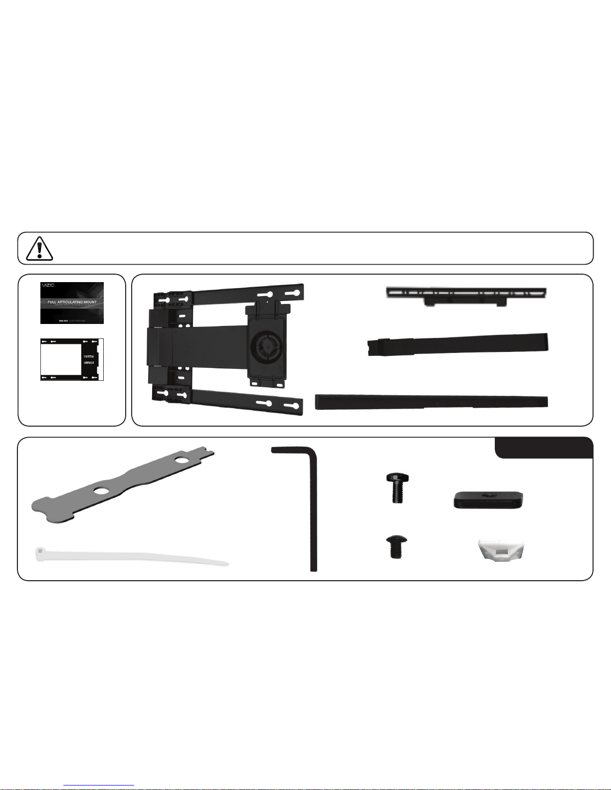
STEP 2 - REVIEW THE PACKAGE CONTENTS
Before you begin, ensure all parts are included and undamaged. To prevent loss, do not unpack the small parts until
they are required. If any parts are missing or damaged, contact VIZIO Customer Service (877) 698-4946.
x 1
x 2
x 2
x 2
x 4
x 4
Sec X1
x 2
x 4
x 1x 4
x 1
(Attached to Mount)
Quick Install Guide &
Wall-Mount Template
2
Page 5
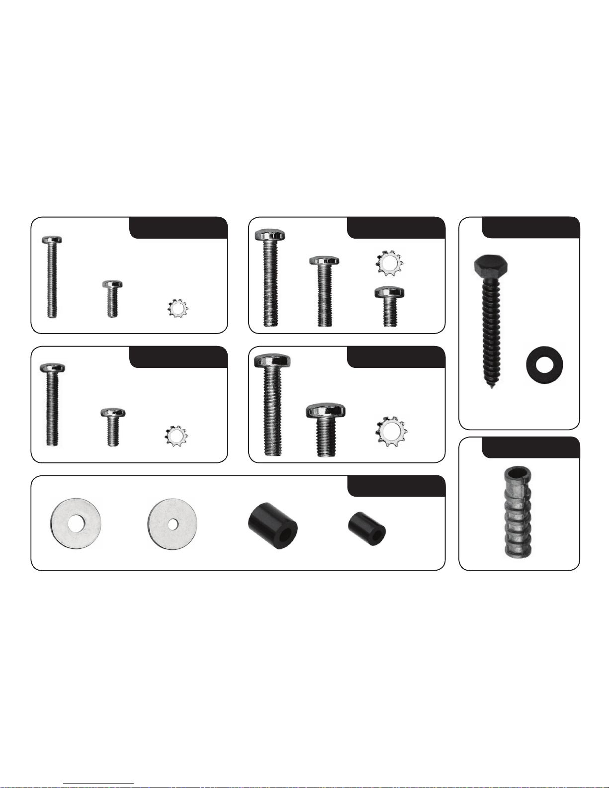
x 4
M4
x 4 x 4
x 4
M5
x 4 x 4 x 4
M8
x 4 x 4
x 4
M6
x 4
x 4
x 4
x 4
MISC
x 4 x 4 x 4
LAG
x 6 x 6
ANCHOR
x 6
3
Page 6
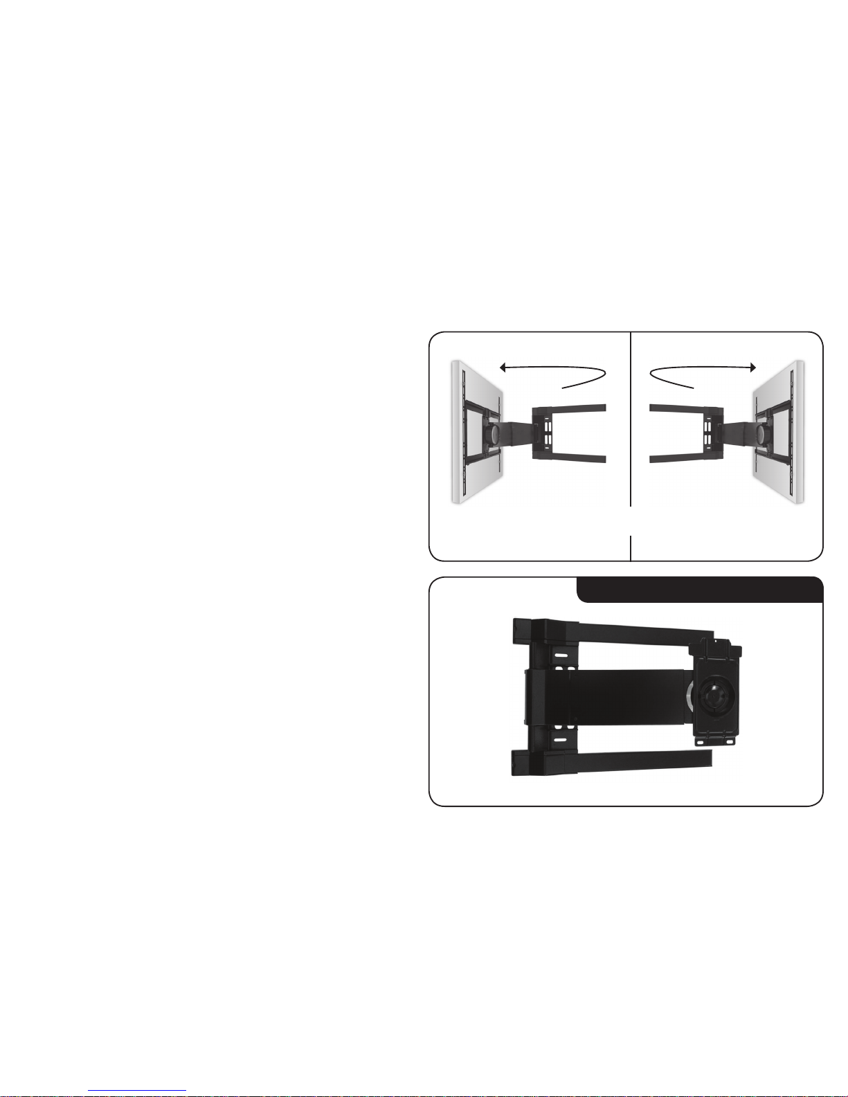
STEP 3 - CHOOSE THE DIRECTION OF SWING ARM
The mount features an arm designed to swing away from the wall
like a door. Like a door, the mount can swing open to the left or to
the right.
Before you begin the installation, you must decide which direction
you want the arm to swing–to the left or to the right.
If you want the arm to swing to the left, do nothing. The mount is
ready to swing to the left as it is assembled in the box.
Go to Step 4 on page 7.
Mount in Box - Ready to Swing Left
Arm Swings Left Arm Swings RightOR
4
Page 7
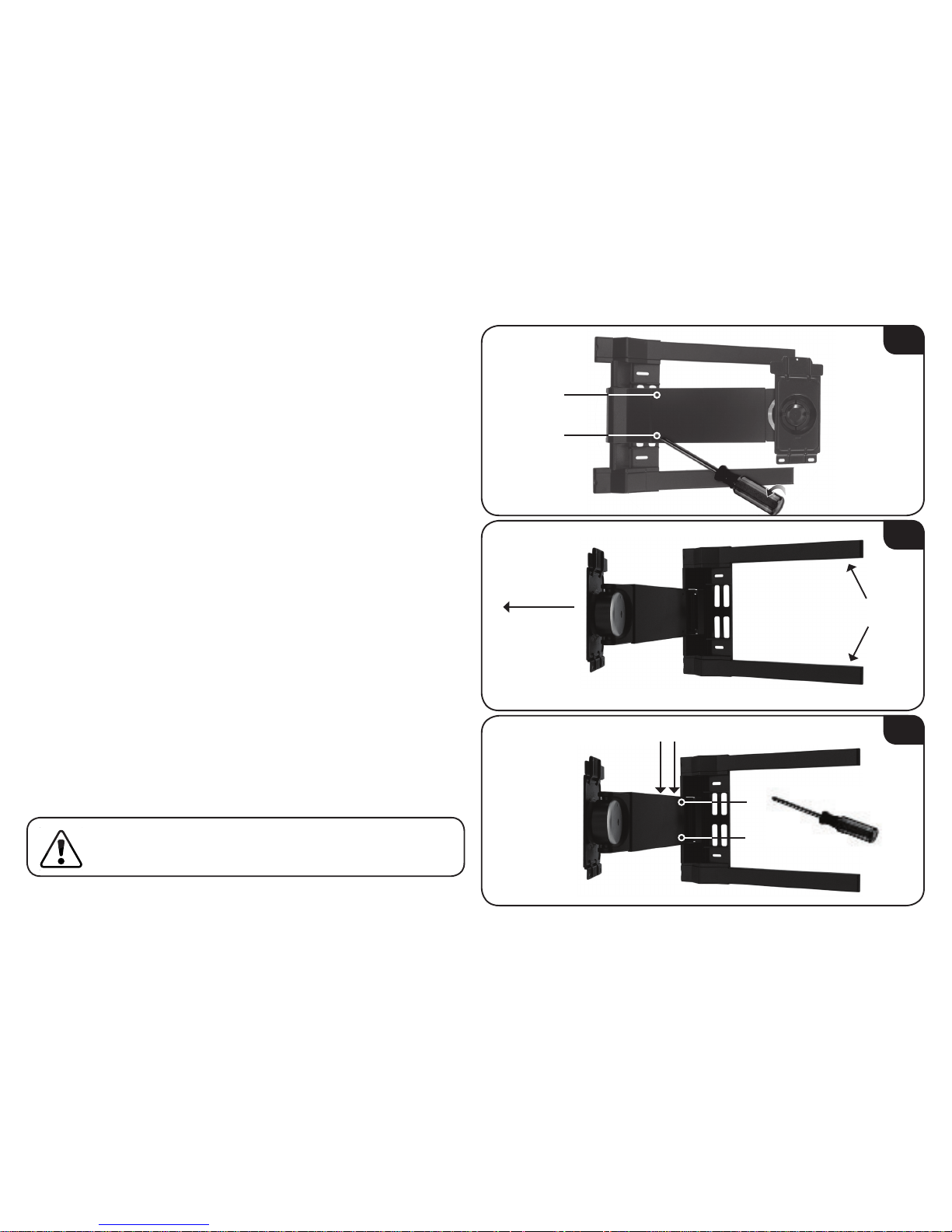
If you want the mount to swing to the right:
1. Lay the mount on the floor. Using the screwdriver, remove the 2
philips-head screws as shown.
2. Hold down the mount as shown and swing the arm away from
the mount.
3. Using the screwdriver, remove the remaining 4 phillips-head
screws from the arm. There are 2 screws inside the arm and 2
screws on the top of the arm.
Hold Down
Swing Arm
Away
2
3
2
1
34
1
2
1
On the top of the arm, do not loosen the screws inside the
row of 9 holes. The correct screws are close to the hinge.
5
Page 8
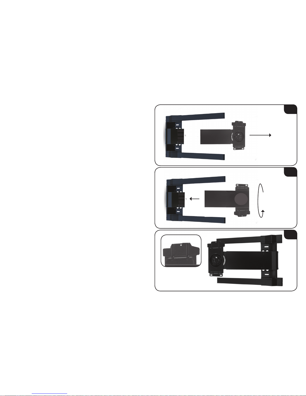
4. Gently separate the arm from the mount.
5. Flip the arm over, then gently reattach the arm to the mount.
6. Using the phillips-head screwdriver, replace the 6 phillips-head
screws. Note that the tab should be on the top of the arm.
The arm is ready to swing to the right.
Go to Step 4 on page 7.
Separate Arm
from Mount
4
5
6
Flip Over
Then Reattach
6
Top of Arm
Has Tab
Page 9
STEP 4 - SET THE LENGTH OF SWING ARM
If you are mounting a 40 - 52” TV, you can adjust the swing arm so
that more of the mount is hidden behind the TV screen.
To adjust the length of the swing arm:
1. Find the size of your TV (reference your TV’s User Guide). Locate
the 9 holes on the top of the swing arm. Determine your TV’s
correct holes using the image at right.
2. Using the screwdriver, remove the 4 screws from the swing arm
as shown. There are 2 screws on the top and 2 inside the wire
management canal on the bottom.
1
2
2
1
3 4
Swing Arm
40 - 48” 50 - 52” 55 - 60”
If your TV is wider than usual due to side speakers or a
large frame/bezel, use holes set for a larger TV.
7
Page 10

3. Push on the end of the swing arm to shorten it. Ensure the holes
for the screws are aligned with the correct holes for your TV’s
size:
• For TVs 40 - 48” use the innermost holes.
• For TVs 50 - 52” use the middle holes.
• For TVs 55 - 60” use the outermost holes.
4. Using the phillips-head screwdriver, replace the 4 screws.
The swing arm is adjusted.
• If you are installing the mount on a wall with wood studs,
go to Step 5A on page 9.
• If you are installing the mount on a concrete wall,
go to Step 5B on page 13.
3
40 - 48” 50 - 52” 55 - 60”
Push End of
Swing Arm
4
2
1
3 4
8
Page 11

STEP 5A - MOUNTING TO A WALL WITH WOOD STUDS
The mount can be attached to walls with wood studs. The wall
covering (drywall, lath, plaster, etc.) may not be thicker than 1/2”.
To attach the mount:
1. Use the electronic stud finder to locate two studs in the wall.
The studs should be approximately 16” apart. Use the pencil to
mark the areas of the wall where the studs are located.
2. Hold the template against the wall, using the pencil marks as a
guide. Ensure 4 holes in the template line up with the studs.
Use the level to level the template.
When the template is level, tape it in place.
1
2
16”
Ensure 4 holes in
template line up
with studs
2
1
3
4
Level
9
Page 12

3
4
3. Using the power drill and the 7/32” drill bit, drill into the top two
template holes. Drill about 2” into the studs.
Remove the template from the wall.
4. Remove 2 lag bolts and 2 washers from the pouch labeled LAG.
Use a wrench to insert the lag bolts and washers into the holes
you just drilled. Do not insert the lag bolts completely. Leave 1/2”
of the bolt showing.
2
1
2
1
10
Page 13

5
6
5. Remove the plastic covers from the mount. Use the thumb holes
to lift the covers away from the mount.
Save the plastic covers. They will be reattached in Step 7.
6. Hang the mount on the wall using the 2 lag bolts, then slide the
mount so the lag bolts are resting in the narrow part of the slot.
Narrow part of slot
Mount, then slide
11
Use the
Thumb Hole
Page 14

7. Ensure the mount is level. Make any necessary adjustments, then
use a wrench to tighten the top 2 lag bolts.
Ensure the bottom mount holes are over a stud. Using the power
drill and the 7/32” drill bit, drill 2 holes in the bottom two mount
holes.
Drill about 2” into the studs.
8. Remove 2 lag bolts and 2 washers from the pouch labeled LAG.
Use a wrench to tighten the lag bolts and washers into the 2
holes you just drilled. Insert the lag bolts completely.
The mount is attached to the wall.
Go to Step 6 on page 16.
7
8
1
2
12
Page 15

STEP 5B - MOUNTING TO A CONCRETE WALL
1
1. Hold the template against the wall, using the level to level the
template.
When the template is level, tape it in place.
2. Using the power drill and the 1/2” drill bit, drill into 6 of the
template holes as shown. Drill about 2 1/2” deep.
Remove the template from the wall.
Level
2
12
3
(choose one)
13
4
(choose one)
65
Page 16

3
4
3. Remove 6 anchors from the pouch labeled ANCHOR.
Push the anchors into the holes you just drilled. Ensure the
anchors are completely inserted and flush with the wall.
4. Remove 6 lag bolts and 6 washers from the pouch labeled LAG.
Use a wrench to tighten the lag bolts and washers into the
anchors. Do not insert the lag bolts completely. Leave 1/2”
of the bolt showing.
14
Page 17

5
6
5. Remove the plastic covers from the mount.
Save the plastic covers. They will be reattached in Step 7.
6. Hang the mount on the wall using the 6 lag bolts, then slide the
mount so the lag bolts are resting in the narrow part of the slot.
Verify that the mount is level. Make small adjustments before
tightening all 6 lag bolts.
The mount is attached to the wall.
Go to Step 6 on page 16.
Narrow part of slot
Mount, then slide
15
Page 18

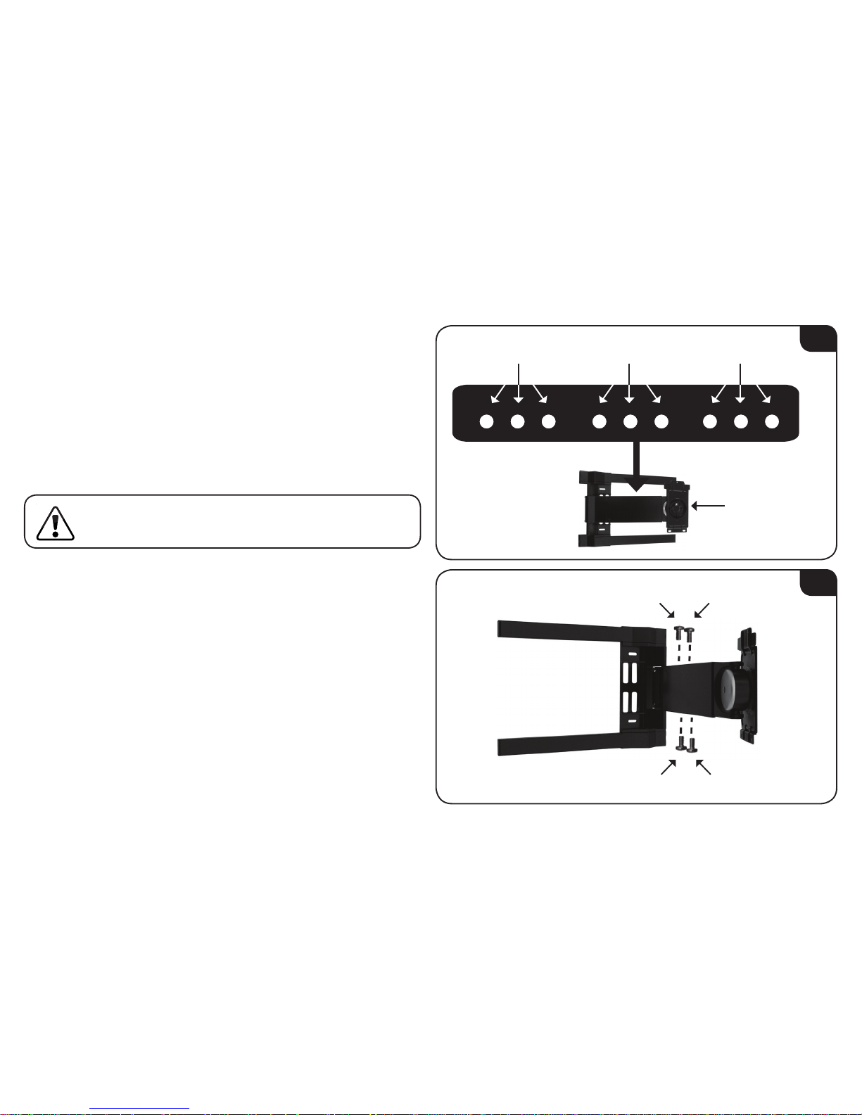
STEP 6 - ATTACHING THE TV BRACKETS
1
1. Gently place the TV on the floor screen-down. You may want to
place a rug or blanket beneath the screen to prevent scratches.
In your TV’s User Guide, find the size of your TV’s mounting holes.
These will be listed as M4, M5, M6, or M8.
Open the pouch labeled with the size that matches your TV’s
mounting holes. If you do not have the User Guide, or the size is
not listed, you may have to try several sizes until you find one
that fits.
2. Place the vertical TV brackets against the mounting holes as
shown. Center them over the mounting holes on the back of the
TV.
If you have a large screen (mounting holes are 400-600mm
apart), place the brackets inward.
If you have a small screen (mounting holes are 200mm apart),
place the brackets outward.
2
Brackets Inward Brackets OutwardOR
Mounting Holes
Mounting Holes
16
Back of TV
Page 19

3. Using the screwdriver, insert the screws, star washers, and
washers as shown.
Because each TV is different, your VIZIO TV mount includes
screws of different lengths. Use screws that can be inserted
completely.
Do not use a short screw if a longer screw can be
inserted completely.
If your TV has a curved back, or if your TV has
protruding components, place spacers between the
brackets and the mounting holes. The spacers are in
the pouch labeled MISC.
If using the M4 or M5 screws, use the small spacers.
If using the M6 or M8 screws, use the large spacers.
3
Without Spacer With Spacer
17
Page 20

4. Center the horizontal brackets over the vertical brackets as
shown.
Open the pouch labeled Sec X1 and remove 4 nuts and
their 4 matching screws.
5. Insert the screws through both the horizontal and vertical TV
brackets. Ensure you attach both the top and bottom horizontal
brackets.
The TV brackets are attached. Go to Step 7 on page 19.
5
x 4
x 4
4
18
Page 21

STEP 7 - HANGING THE TV ON THE MOUNT
1. Swing the arm away from the mount.
2. With the help of another person, lift the TV and hang it on the
mount arm as shown.
First, hang the top bracket on the arm. The tab on the mount arm
fits into the slot on the horizontal bracket.
Then, gently lower the bottom bracket so it rests against the arm.
This step requires lifting the TV. To prevent injury to
yourself or damage to your TV, perform this step with the
help of another person.
2
1
Swing Arm
Away
1
2
19
Tab on Arm Fits
into Slot
on Bracket
Page 22

3. Remove the locking tool and 2 security screws from the pouch
labeled Sec X1.
Using the locking tool, insert and tighten the 2 security screws
as shown.
4. Place the locking tool inside one of the mount brackets, then
snap the plastic covers back into place. By saving the locking tool
in this place, you can remove the security screws later.
The mount setup is complete.
For information on positioning the TV and managing cables,
see Step 8 on page 21.
4
3
Locking Tool
20
Page 23

STEP 6 - FINAL ADJUSTMENTS
Using the included zip-ties, you can bundle and hide your TV’s
cables.
1. To bundle and hide your TV’s cables, take the 4 zip-ties and
4 sticky mounts from the pouch labeled Sec X1.
Bundle the cables together and wrap them with zip-ties. Before
closing the zip-ties, lace each one through a sticky mount as
shown.
2. Remove the backing from each sticky mount and push the cables
into the cavity running along the bottom of the mount arm.
2
1
1 4
3
2
21
Page 24

If necessary
, you can adjust both the swivel and tilt of the TV.
Remove the allen wrench from the pouch labeled Sec X1.
1. Using the allen wrench, adjust the swivel tension by adjusting
the top and bottom screws as shown.
2. Using the allen wrench, adjust the tilt tension by adjusting the
center screw as shown.
1
22
2
Page 25

WARRANTY
ON PARTS AND LABOR
Covers units purchased as new in United States and Puerto Rico Only.
VIZIO provides a warranty to the original purchaser of a new Product against defects in
materials and workmanship for a period of one year of non-commercial usage and ninety
(90) days of commercial use. If a Product covered by this warranty is determined to be
defective within the warranty period, VIZIO will either repair or replace the Product at its
sole option and discretion.
To obtain warranty service, contact VIZIO Technical Support via e-mail: TechSupport@
VIZIO.com or via phone at 877 MY VIZIO (877.698.4946) from 6:00AM to 9:00PM Monday
through Friday and 8:00AM to 4:00PM Saturday and Sunday, Pacific Time, or visit www.
VIZIO.com. PRE-AUTHORIZATION MUST BE OBTAINED BEFORE SENDING ANY PRODUCT
TO A VIZIO SERVICE CENTER. Proof of purchase in the form of a purchase receipt or copy
thereof is required to show that a Product is within the warranty period.
Parts and Labor
There will be no charge for parts or labor during the warranty period. Replacement parts
and Products may be new or recertified at VIZIO’s option and sole discretion. Replacement
parts and Products are warranted for the remaining portion of the original warranty or for
ninety (90) days from warranty service or replacement, whichever is greater.
Type of Service
Defective Products must be sent to a VIZIO service center to obtain warranty service.
VIZIO is not responsible for transportation costs to the service center, but VIZIO will cover
return shipping to the customer. PRE-AUTHORIZATION IS REQUIRED BEFORE SENDING ANY
PRODUCT TO A VIZIO SERVICE CENTER FOR WARRANTY SERVICE.
Product returns to VIZIO’s service centers must utilize either the original carton box and
shipping material or packaging that affords an equal degree of protection. VIZIO Technical
Support will provide instructions for packing and shipping the covered Product to the VIZIO
service center.
Limitations and Exclusions
VIZIO’s one-year limited warranty only covers defects in materials and workmanship.
This warranty does not cover, for example: cosmetic damage, normal wear and tear,
improper operation, improper voltage supply or power surges, signal issues, damages
from shipping, acts of God, any type of customer misuse, modifications or adjustments, as
well as installation and set-up issues or any repairs attempted by anyone other than by a
VIZIO authorized service center. Products with unreadable or removed serial numbers, or
requiring routine maintenance are not covered. This one year limited warranty does not
cover Products sold “AS IS”, “FACTORY RECERTIFIED”, or by a non-authorized reseller.
THERE ARE NO EXPRESS WARRANTIES OTHER THAN THOSE LISTED OR DESCRIBED
ABOVE. ANY IMPLIED WARRANTIES, INCLUDING ANY IMPLIED WARRANTY OF MERCHANTABILITY AND FITNESS FOR A PARTICULAR PURPOSE, SHALL BE LIMITED IN DURATION
TO THE PERIOD OF TIME SET FORTH ABOVE. VIZIO’S TOTAL LIABILITY FOR ANY AND ALL
LOSSES AND DAMAGES RESULTING FROM ANY CAUSE WHATSOEVER INCLUDING VIZIO’S
NEGLIGENCE, ALLEGED DAMAGE, OR DEFECTIVE GOODS, WHETHER SUCH DEFECTS ARE
DISCOVERABLE OR LATENT, SHALL IN NO EVENT EXCEED THE PURCHASE PRICE OF THE
PRODUCT. VIZIO SHALL NOT BE RESPONSIBLE FOR LOSS OF USE, LOSS OF INFORMATION
OR DATA, COMMERCIAL LOSS, LOST REVENUE OR LOST PROFITS, OR OTHER INCIDENTAL
OR CONSEQUENTIAL DAMAGES. SOME STATES DO NOT ALLOW LIMITATIONS ON
HOW LONG AN IMPLIED WARRANTY LASTS OR THE EXCLUSION OF INCIDENTAL OR
CONSEQUENTIAL DAMAGES, SO THE ABOVE LIMITATIONS OR EXCLUSIONS MAY NOT APPLY
TO YOU. THIS WARRANTY GIVES YOU SPECIFIC LEGAL RIGHTS, AND YOU MAY ALSO HAVE
OTHER RIGHTS, WHICH VARY FROM STATE TO STATE. THIS WARRANTY IS SUBJECT TO
CHANGE WITHOUT NOTICE.
CHECK WWW.VIZIO.COM FOR THE MOST CURRENT VERSION.
23
Page 26

24
TECHNICAL SUPPORT
Products are often returned due to a technical problem rather than a
defective product that may result in unnecessary shipping charges
billed to you. Our trained support personnel can often resolve the
problem over the phone. For more information on warranty service
or repair, after the warranty period, please contact our Support
Department at the number below.
Customer support and quality service are integral parts of VIZIO’s
commitment to service excellence. For technical assistance contact
our VIZIO Technical Support Department via email or phone. Please
have your VIZIO model number, serial number, and date of purchase
available before your call.
Address:
Phone:
Fax:
Email:
Web:
39 Tesla
Irvine, CA 92618, USA
(877) 698-4946
(949) 585-9563
techsupport@vizio.com
www.vizio.com
Hours of operation:
Monday - Friday: 6 am to 9 pm (PST)
Saturday - Sunday: 8 am to 4pm (PST)
NOTES
Page 27

Page 28

TRADEMARKS SHOWN ARE THE PROPERTY OF THEIR RESPECTIVE OWNERS. IMAGES USED ARE FOR ILLUSTRATION PURPOSES ONLY. VIZIO, THE V LOGO, WHERE VISION MEETS VALUE,
AND OTHER VIZIO TRADEMARKS ARE THE INTELLECTUAL PROPERTY OF VIZIO INC. PRODUCT FEATURES AND SPECIFICATIONS ARE SUBJECT TO CHANGE WITHOUT NOTICE.
© 2010 VIZIO INC. ALL RIGHTS RESERVED.
100907ST-NC
 Loading...