

Vivotek IP8335HIP8335H, IP8335H User Manual
IP8335HIP8335H
720p HD • IR Illuminators • WDR Pro
Rev. 1.0

VIVOTEK
2 - User's Manual
Table of Contents
Overview...................................................................................................................................................................... 4
Read Before Use .................................................................................................................................................... 5
Package Contents .................................................................................................................................................. 5
Symbols and Statements in this Document ............................................................................................................ 5
Physical Description ............................................................................................................................................... 6
Hardware Installation .............................................................................................................................................. 7
Network Deployment ............................................................................................................................................ 11
Network Deployment ................................................................................................................................................. 12
Setting up the Network Camera over the Internet ................................................................................................ 12
Software Installation ............................................................................................................................................. 14
Ready to Use ........................................................................................................................................................ 15
Accessing the Network Camera ................................................................................................................................ 17
Using Web Browsers ............................................................................................................................................ 17
Using RTSP Players ............................................................................................................................................. 19
Using 3GPP-compatible Mobile Devices .............................................................................................................. 20
Using VIVOTEK Recording Software ................................................................................................................... 21
Main Page .................................................................................................................................................................22
Client Settings ...........................................................................................................................................................27
H.264 / MPEG-4 Media Options ....................................................................................................................... 27
H.264 / MPEG-4 Protocol Options ................................................................................................................... 27
MP4 Saving Options ......................................................................................................................................... 28
Local Streaming Buffer Time ............................................................................................................................ 28
Conguration ............................................................................................................................................................. 29
System > General settings ................................................................................................................................... 30
System > Homepage layout ................................................................................................................................ 32
System > Logs ..................................................................................................................................................... 35
System > Parameters .......................................................................................................................................... 36
System > Maintenance ......................................................................................................................................... 37
Security > User Account ....................................................................................................................................... 41
Security > HTTPS (Hypertext Transfer Protocol over SSL) .......................................................................42
Security > Access List ........................................................................................................................................ 47
Security > IEEE 802.1x .................................................................................................................................... 50
Network > General settings .................................................................................................................................. 52
Network > Streaming protocols .......................................................................................................................... 60
Network > QoS (Quality of Service) .................................................................................................................. 64
Network > DDNS ................................................................................................................................................ 66
Network > SNMP (Simple Network Management Protocol)
........................................................................ 69
Media > Image ................................................................................................................................................... 70
General settings .............................................................................................................................................. 70

VIVOTEK
User's Manual - 3
Day/Night Settings ............................................................................................................................................71
Preference ....................................................................................................................................................... 72
Exposure
........................................................................................................................................................
74
Privacy mask ................................................................................................................................................. 77
Media > Video ......................................................................................................................................................78
Stream settings
.............................................................................................................................................
78
Media > Audio ...................................................................................................................................................... 82
Audio Settings ..................................................................................................................................................82
PTZ > PTZ settings .............................................................................................................................................83
Digital PTZ Operation (E-PTZ Operation) ........................................................................................................83
Mechanical PTZ Operation (When camera is mounted on an external pan/tilt head) ...................................... 86
Event > Event settings .........................................................................................................................................91
Event ...............................................................................................................................................................91
Add server ........................................................................................................................................................ 94
Add media ........................................................................................................................................................98
Applications > Motion detection..........................................................................................................................104
Applications > DI and DO ................................................................................................................................. 107
Applications > Tampering detection ...................................................................................................................107
Recording > Recording settings ........................................................................................................................ 108
Local storage > SD card management ............................................................................................................... 113
SD card staus ................................................................................................................................................. 113
SD card control ............................................................................................................................................... 113
Local storage > Content management ............................................................................................................... 114
Searching and Viewing the Records .............................................................................................................. 114
Search Results ............................................................................................................................................... 114
Appendix
...........................................................................................................................................................
116
URL Commands for the Network Camera .......................................................................................................... 11 6
1. Overview .................................................................................................................................................... 116
2. Style Convention ........................................................................................................................................ 116
Technical Specications .....................................................................................................................................186
Technology License Notice ................................................................................................................................. 187
MPEG-4 AAC Technology ..............................................................................................................................187
MPEG-4 Visual Technology ............................................................................................................................ 187
AMR-NB Standard ..........................................................................................................................................187
Electromagnetic Compatibility (EMC) .................................................................................................................188
Revision History
Rev. 1.0: Initial release.

VIVOTEK
4 - User's Manual
Overview
VIVOTEK’s IP8335H network bullet camera features an HD WDR CMOS sensor for use in
challenging lighting conditions. The resulting WDR Pro feature enables the camera to capture
both the dark and bright parts of an image with double shutters, enabling two frames to be
combined to generate a highly realistic image representative of the original scene, providing
video quality close to the capabilities of the human eye. The P-iris lens controls the iris with
extreme precision with its built-in stepper motor, maintaining the opening at an optimal level at
all times, resulting in superior image clarity and depth of eld as well as image quality. As such,
the IP8335H is suitable for high contrast environments such as lobby entrances, parking lots,
ATMs, loading areas, and much more.
The day and night functionality and the IP67-rated weatherproof housing of the IP8335H allows
users to easily build a cost-effective IP surveillance system without additional accessories.
Incorporating an IR-cut filter that can be removed automatically at night and built-in IR
illuminators with coverage for up to 20 meters, the IP8335H is an outstanding choice for a 24hour surveillance solution.
VIVOTEK
User's Manual - 5
■ IP8335H - the Network Camera
■ Alignment Sticker
■ Sun Shield, Wrench, RJ45 Female/Female
Coupler, Double-sided Tape, Screws
■ Power Adapter
■ Wall Mount Bracket & Mounting Plate
■ Waterproof Connector (for backup use)
■ Moisture Absorber
■ Quick Installation Guide / Warranty Card
■ Software CD
Read Before Use
The use of surveillance devices may be prohibited by law in your country. The Network Camera is not
only a high-performance web-ready camera but can also be part of a exible surveillance system. It is
the user’s responsibility to ensure that the operation of such devices is legal before installing this unit for
its intended use.
It is important to rst verify that all contents received are complete according to the Package Contents
listed below. Take note of the warnings in the Quick Installation Guide before the Network Camera is
installed; then carefully read and follow the instructions in the Installation chapter to avoid damage due to
faulty assembly and installation. This also ensures the product is used properly as intended.
The Network Camera is a network device and its use should be straightforward for those who have basic
networking knowledge. It is designed for various applications including video sharing, general security/
surveillance, etc. The Configuration chapter suggests ways to best utilize the Network Camera and
ensure proper operations. For creative and professional developers, the URL Commands of the Network
Camera section serves as a helpful reference to customizing existing homepages or integrating with the
current web server.
Package Contents
Symbols and Statements in this Document
i
INFORMATION: provides important messages or advices that might help prevent inconvenient
or problem situations.
NOTE: Notices provide guidance or advices that are related to the functional integrity of the
machine.
Tips: Tips are useful information that helps enhance or facilitae an installation, function, or
process.
WARNING! or IMPORTANT!: These statements indicate situations that can be dangerous or
hazardous to the machine or you.
Electrical Hazard: This statement appears when high voltage electrical hazards might occur
to an operator.
VIVOTEK
6 - User's Manual
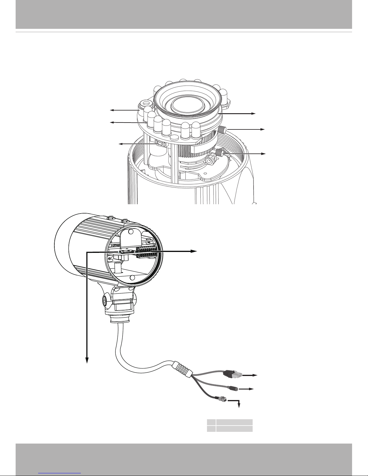
Physical Description
IR LEDs
Lens
Light Sensor
Zoom Controller
Focus Controller
Reset Button
General I/O
Terminal Block
Micro SD/SDHC
Card Slot
Alternate AC Power Source
Gb Ethernet
RJ45 Plug
Power Cord Socket
+ AC 24V +
- AC 24V -
VIVOTEK
User's Manual - 7
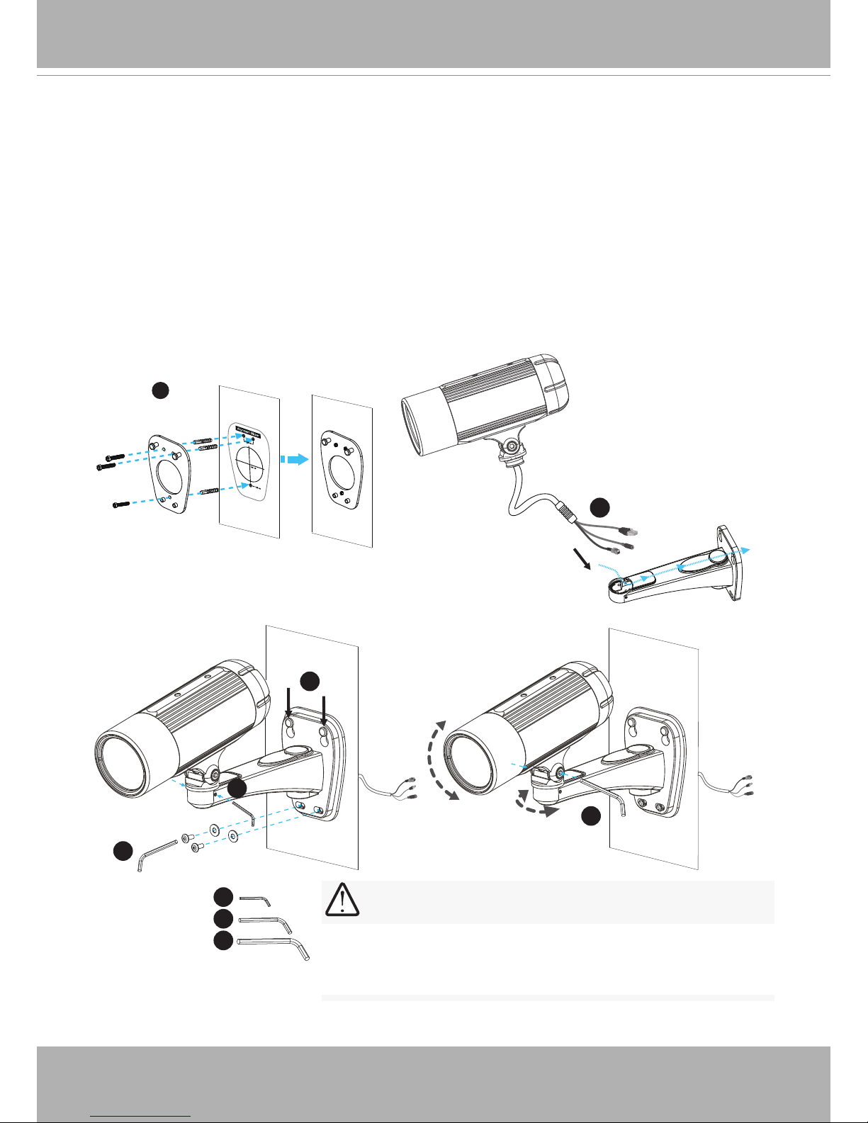
Hardware Installation
1. Attach the alignment sticker to the wall. Drill three holes into the wall. Then hammer the
supplied plastic anchors into the holes and secure the plate with supplied screws.
2. Feed the cables through the front opening of the wall mount bracket. (If you want to use
external devices such as sensors and alarms, please refer to the assembling steps on the
next page.)
3. Hang the wall mount bracket on the plate.
4. Fix the Network Camera on the wall mount bracket with two screws on both sides.
5. Secure the wall mount bracket with the supplied screws.
6. Adjust the angle of the wall mount bracket to aim at the shooting area.
1
2
5
4
3
6
5
4
6
The supplied L-type hex key wrenches are exclusively designed
to match each screw. In case you will need to adjust the lens
later, do not discard the wrenches.
IMPORTANT!
VIVOTEK
8 - User's Manual
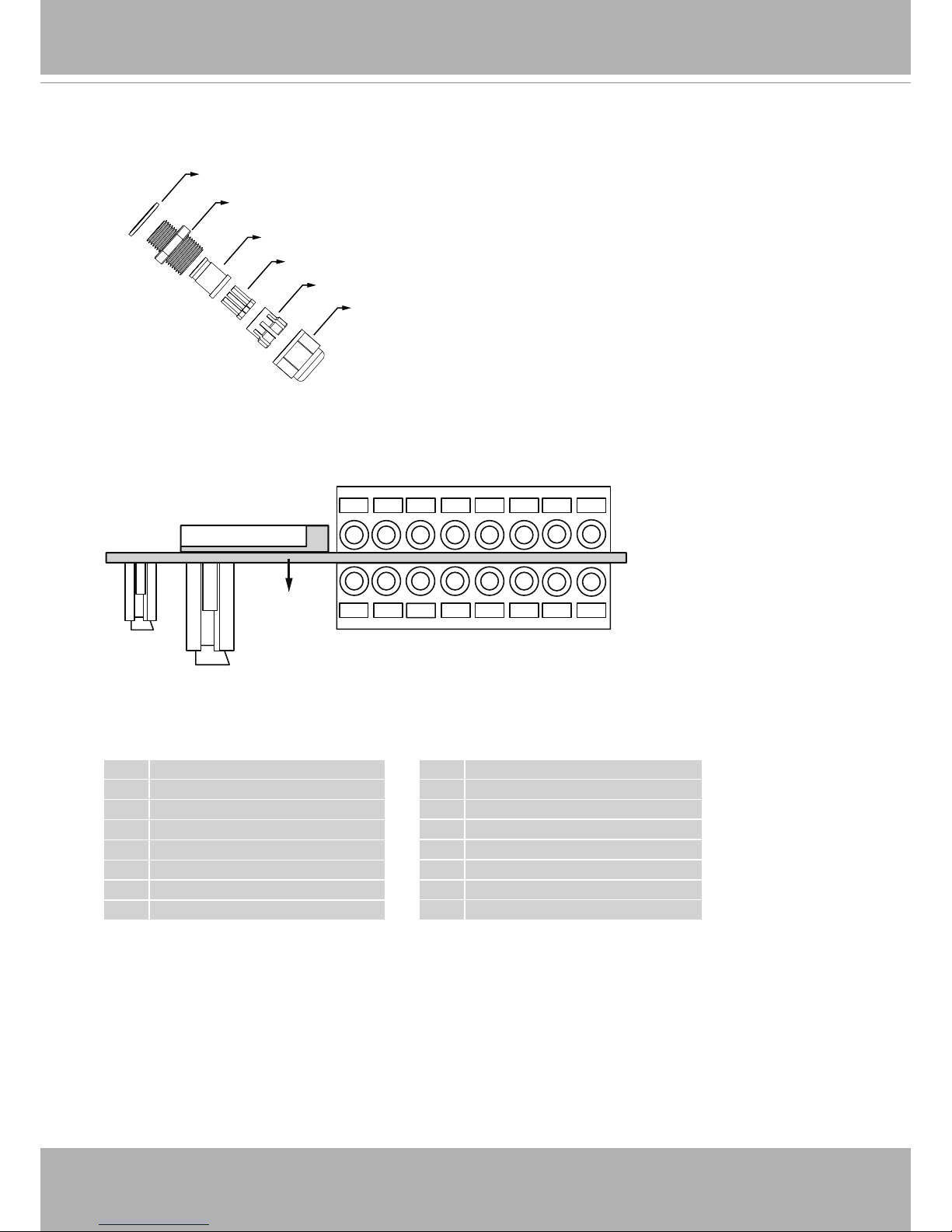
Waterproof Connector
Rubber (A)
Screw Nut (B)
Seal (C)
Seals (D)
Housing (E)
Sealing Nut (F)
Components of the Waterproof Connector
IO Block Pin Denitions
1 N/C
2 N/C
3 DO- *
4 DO+ **
5 Digital Input: - (Ground)
6 Digital Input 3: DI3
7 Digital Input: - (Ground)
8 Digital Input 2: DI2
87654321
J3
J7
87654321
J7
1 Digital Input 1: DI1
2 Digital Input: - (Ground)
3 RS485 +
4 RS485 5 AUDIO_GND
6 AUDIO_IN: Ext_MIC_IN
7 AUDIO_GND
8 AUDIO_OUT
J3
* Vmax.: 40V DC, Imax.: 400mA.
** Power output, 12V DC: max. load is 50mA.
The terminal block is accessible when the rear cover is opened.
Power
PCB
Micro SD Socket
Ethernet
VIVOTEK
User's Manual - 9
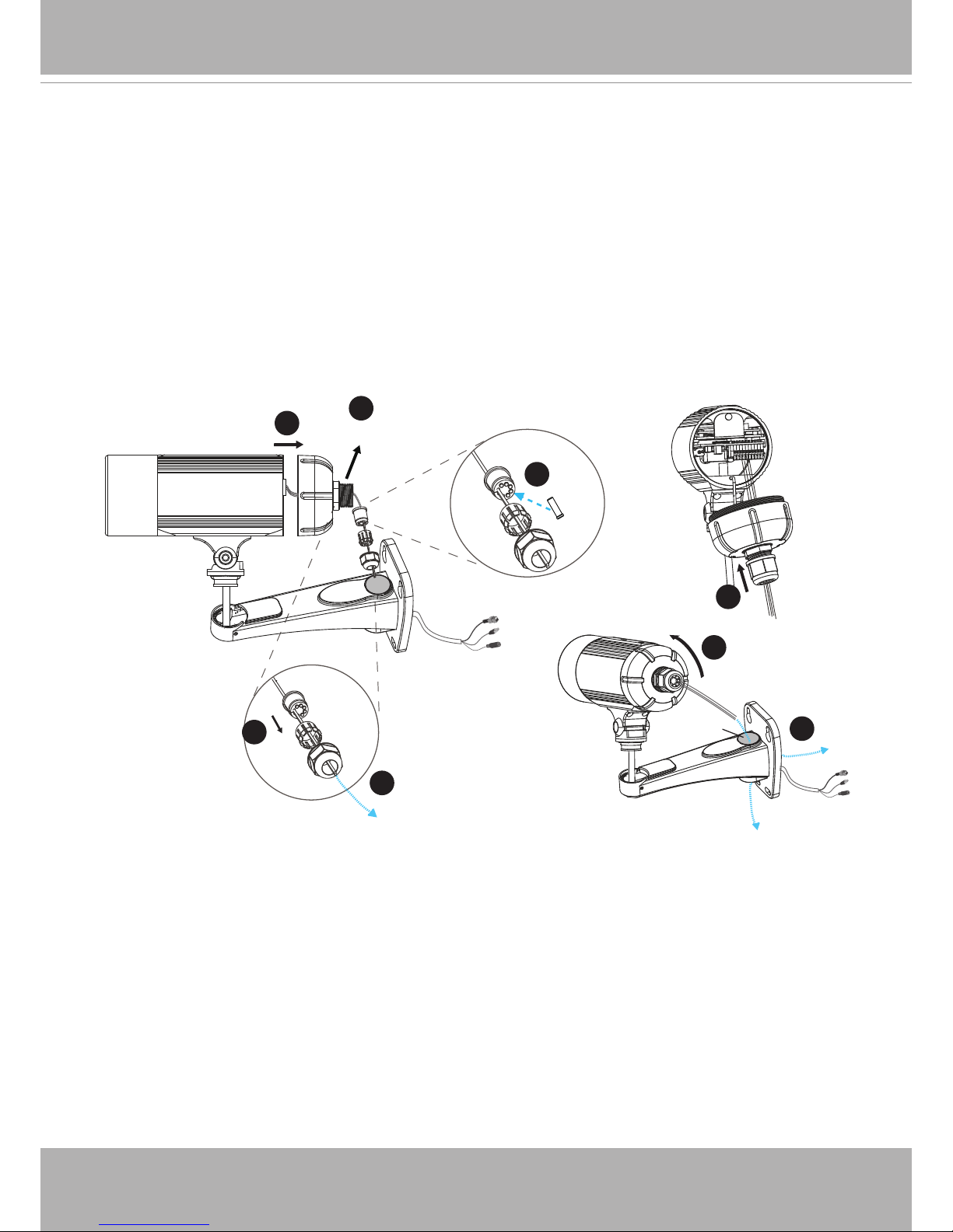
Assembling Steps
(A)+(B)
2
6
(E)
(C)
(F)
(D)
(C)
4
7
(E)
(F)
3
(C)
5
8
9
(F)
(G)
1. Disassemble the components of the waterproof connector into part (A) ~ (F) as shown above.
2. Remove the rubber stopper from the bottom of the Network Camera and secure the rubber (A)
and screw nut (B) tightly.
3. Open the back cover of the Network Camera.
4. If you have external devices such as sensors and alarms, feed the cables through the
waterproof connector (F --> E --> C --> A+B) as the illustration shown below. Then refer to
the pin denition to connect them to the general I/O terminal block. Note: The recommended
cable gauge is 2.0 ~ 2.8 mm.
5. Push the seal (C) into the housing (E).
6. Insert the seals (D) into the empty holes on the seal (C) to avoid moisture.
7. Secure the sealing nut (F) tightly.
8. Tighten the back cover.
9. Remove rubber (G) and feed the cables through the wall mount bracket.
VIVOTEK
10 - User's Manual
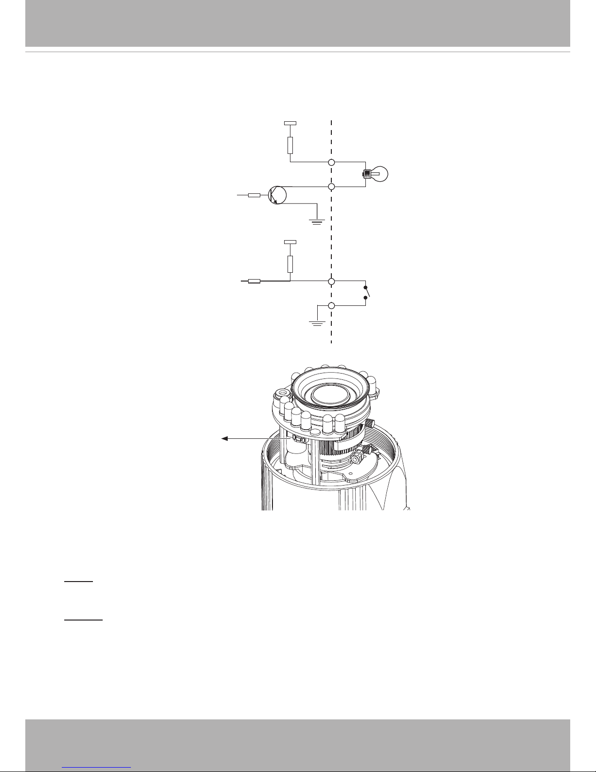
DI/DO Diagram
Please refer to the following illustration for the connection method.
Hardware Reset
The reset button is used to reset the system or restore the factory default settings. Sometimes
resetting the system can return the camera to normal operation. If the system problems remain
after reset, press the reset button longer to restore the factory settings and install again.
Reset: Press and release the recessed reset button with a straightened paper clip. Wait for the
Network Camera to reboot.
Restore: Press and hold the recessed reset button for at least several seconds to restore. Note
that all settings will be restored to factory defaults.
SD/SDHC Card Capacity
This network camera is compliant with Micro SD/SDHC 32GB and other preceding standard SD
cards.
12V
+12V
Digital output
PIN 1
Power+12V
PIN 2
Digital input
PIN 3
Ground
PIN 4
Reset Button
VIVOTEK
User's Manual - 11
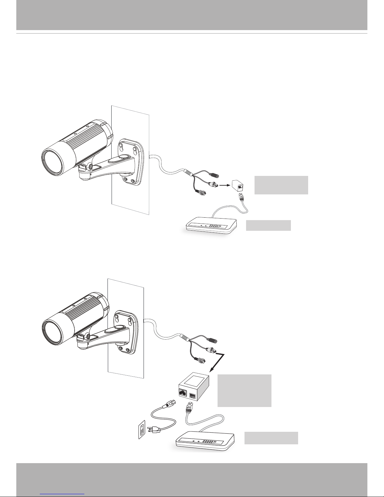
The Network Camera is PoE-compliant, allowing transmission of power and data via a single
Ethernet cable. Follow the below illustration to connect the Network Camera to a PoE-enabled
switch via Ethernet cable.
Use a PoE power injector (optional) to connect between the Network Camera and a non-PoE
switch.
Network Deployment
When using a PoE-enabled switch
RJ45 Female/
Female Coupler
When using a non-PoE switch
POWER
COLLISION
LINK
RECEIVE
PARTITION
1
2
3
4
5
PoE Switch
POWER
COLLISION
LINK
RECEIVE
PARTITION
1
2
3
4
5
PoE Power
Injector
(Optional)
Non-PoE Switch
VIVOTEK
12 - User's Manual
Network Deployment
Setting up the Network Camera over the Internet
There are several ways to set up the Network Camera over the Internet. The rst way is to set
up the Network Camera behind a router. The second way is to utilize a static IP. The third way is
to use PPPoE.
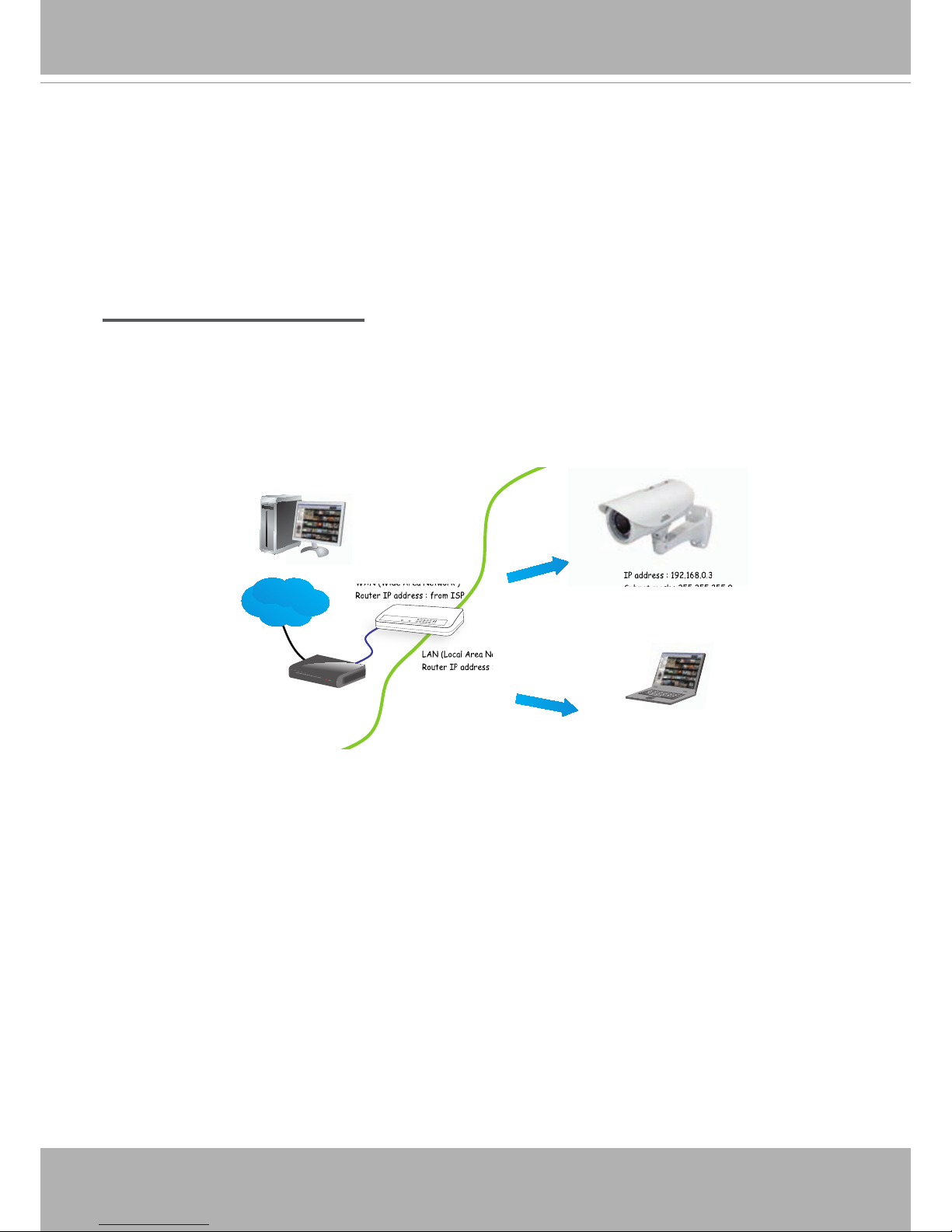
Internet connection via a router
Before enabling the access to the Network Camera over the Internet, make sure you have a
router and follow the steps below.
1. Connect your Network Camera behind a router, the Internet environment is illustrated below.
Regarding how to obtain your IP address, please refer to Software Installation on page 13 for
details.
2. In this case, if the Local Area Network (LAN) IP address of your Network Camera is
192.168.0.3, please forward the following ports for the Network Camera on the router.
■ Secondary HTTP port
■ RTSP port
■ RTP port for audio
■ RTCP port for audio
■ RTP port for video
■ RTCP port for video
If you have changed the port numbers on the Network page, please open the ports
accordingly on your router. For information on how to forward ports on the router, please refer
to your router’s user’s manual.
3. Find out the public IP address of your router provided by your ISP (Internet Service Provider).
Use the public IP and the secondary HTTP port to access the Network Camera from the
Internet. Please refer to Network Type on page 51 for details.
IP address : 192.168.0.3
Subnet mask : 255.255.255.0
Default router : 192.168.0.1
IP address : 192.168.0.2
Subnet mask : 255.255.255.0
Default router : 192.168.0.1
LAN (Local Area Network)
Router IP address : 192.168.0.1
WAN (Wide Area Network )
Router IP address : from ISP
Cable or DSL Modem
L
A
N (
Local Area Network)
R
o
u
t
e
r
I
P
a
d
dre
s
s
W
A
N (Wide Area Network )
R
o
u
t
e
r
I
P
a
d
dre
s
s
f
r
o
m
I
S
P
POWER
COLLISION
LINK
RECEIVE
PARTITION
1
2
3
4
5
Internet
I
P
a
d
dre
s
s
1
9
2
.
1
6
8
.0.
3

VIVOTEK
User's Manual - 13
Internet connection with static IP
Choose this connection type if you are required to use a static IP for the Network Camera.
Please refer to LAN conguration on page 51 for details.
Internet connection via PPPoE (Point-to-Point over Ethernet)
Choose this connection type if you are connected to the Internet via a DSL Line. Please refer to
PPPoE on page 49 for details.
VIVOTEK
14 - User's Manual
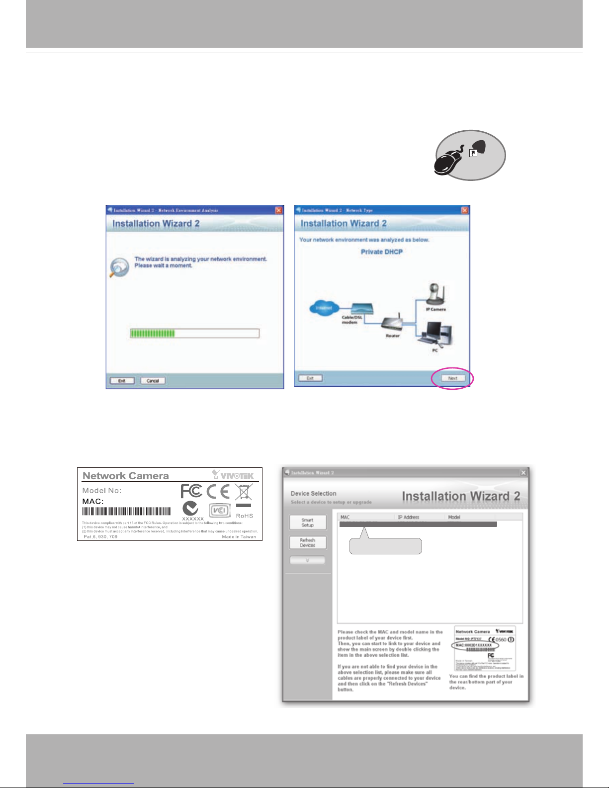
Software Installation
Installation Wizard 2 (IW2), free-bundled software included on the product CD, helps you set up
your Network Camera on the LAN.
1. Install IW2 under the Software Utility directory from the software CD.
Double click the IW2 shortcut on your desktop to launch the program.
2. The program will conduct an analysis of your network environment.
After your network environment is analyzed, please click Next to continue the program.
3. The program will search for all VIVOTEK network devices on the same LAN.
4. After a brief search, the main installer window will pop up. Double-click on the MAC address
that matches the one printed on the camera label or the S/N number on the package box label
to open a browser management session with the Network Camera.
Installation
Wizard 2
IW
2
0002D107258A
00-02-D1-07-25-8A 192.168.5.151 IP8335H
0002D1083236
IP8335H
VIVOTEK
User's Manual - 15
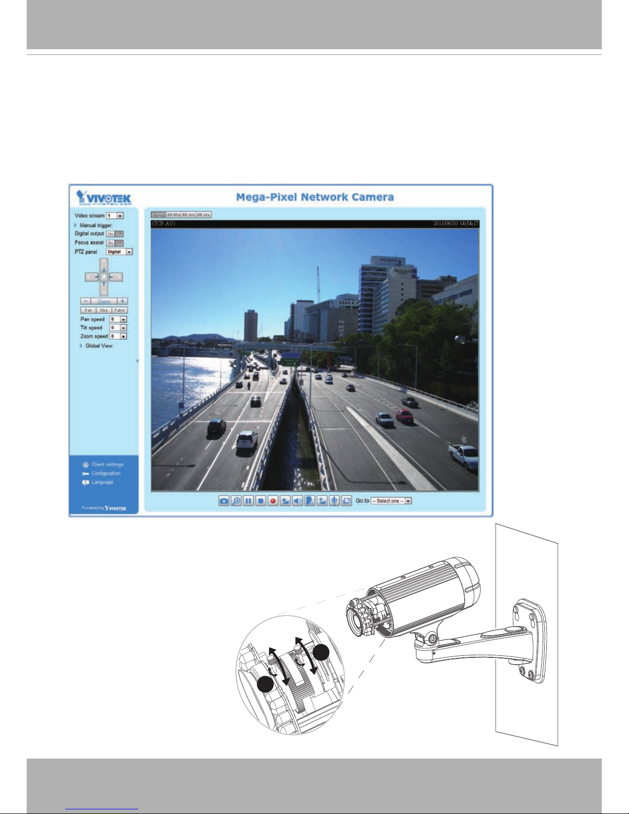
Ready to Use
1. A browser session with the Network Camera should prompt as shown below.
2. You should be able to see live video from your camera. You may also install the 32-channel
recording software from the software CD in a deployment consisting of multiple cameras. For
its installation details, please refer to its related documents.
3. Unscrew the zoom controller to adjust the zoom
factor. Upon completion, tighten the zoom
controller.
4. Unscrew the focus controller to adjust the focus
range. Upon completion, tighten the focus
controller.
T
W
∞
N
3
4
VIVOTEK
16 - User's Manual
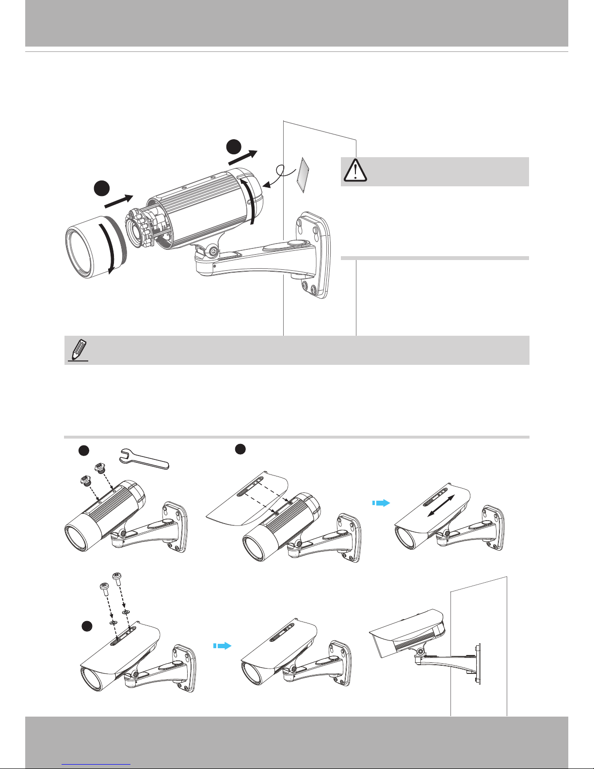
5. Tighten the lens cover.
6. Replace the moisture absorber with a new one if you open the back cover during the
installation procedure.
5
6
IMPORTANT!
1
2
3
Please tear down the aluminum
foil vacuum bag and take out the
moisture absorber, and then replace
it with the absorber in kit using a
double-sided tape.
NOTE:
If you want to use the supplied sun shield for outdoor environments, please follow the steps
below to install:
1. Tighten the supplied two screws.
2. Attach the supplied sun shield to the Network Camera and slide it to the desired position.
3. Fix the sun shield with the supplied two screws.
VIVOTEK
User's Manual - 17
Accessing the Network Camera
This chapter explains how to access the Network Camera through web browsers, RTSP players,
3GPP-compatible mobile devices, and VIVOTEK recording software.
Using Web Browsers
Use Installation Wizard 2 (IW2) to access the Network Cameras on the LAN.
If your network environment is not a LAN, follow these steps to access the Network Camera:
1. Launch your web browser (ex. Microsoft
®
Internet Explorer or Mozilla Firefox).
2. Enter the IP address of the Network Camera in the address eld. Press Enter.
3. The live video will be displayed in your web browser.
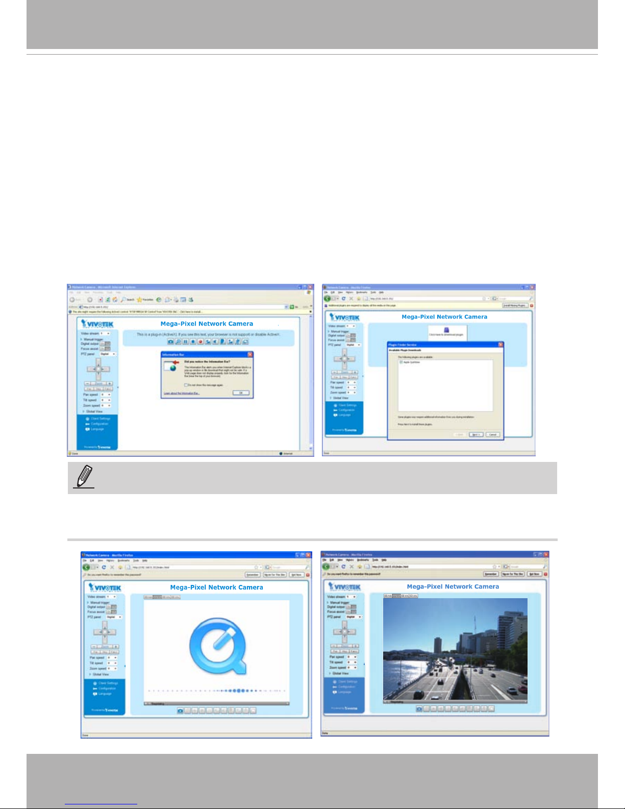
4. If it is the rst time installing the VIVOTEK network camera, an information bar will prompt as
shown below. Follow the instructions to install the required plug-in on your computer.
NOTE:
For Mozilla Firefox or Netscape users, your browser will use Quick Time to stream live video.
If you do not have Quick Time on your computer, please download Quick Time from Apple
Inc's website, and then launch your web browser.

VIVOTEK
18 - User's Manual
To enable the ActiveX® Controls for your browser:
3. Refresh your web browser, then install the ActiveX
®
control. Follow the instructions to
complete installation.
1. Choose Tools > Internet Options > Security
> Custom Level.
2. Look for Download signed ActiveX® controls;
select Enable or Prompt. Click OK.
NOTE:
1. By default, your Network Camera is not password-protected. To prevent unauthorized
access, it is highly recommended to congure a password for your camera later.
For more
information about how to enable password protection, please refer to Security on page 40
.
2. If you see a dialogue box indicating that your security settings prohibit running ActiveX
Controls®, please enable ActiveX Controls for your browser.

VIVOTEK
User's Manual - 19
IMPORTANT!
•
Currently the Network Camera utilizes 32-bit ActiveX plugin. You CAN NOT open a
management/view session with the camera using a 64-bit IE browser.
•
If you encounter this problem, try execute the Iexplore.exe program from C:\
Windows\SysWOW64. A 32-bit version of IE browser will be installed.
•
On Windows 7, the 32-bit explorer browser can be accessed from here:
C:\Program Files (x86)\Internet Explorer\iexplore.exe
VIVOTEK
20 - User's Manual
Using RTSP Players
To view the H.264/MPEG-4 streaming media using RTSP players, you can use one of the
following players that support RTSP streaming.
Quick Time Player
Real Player
As most ISPs and players only allow RTSP streaming through port number 554, please set the
RTSP port to 554. For more information, please refer to RTSP Streaming on page 60.
For example:
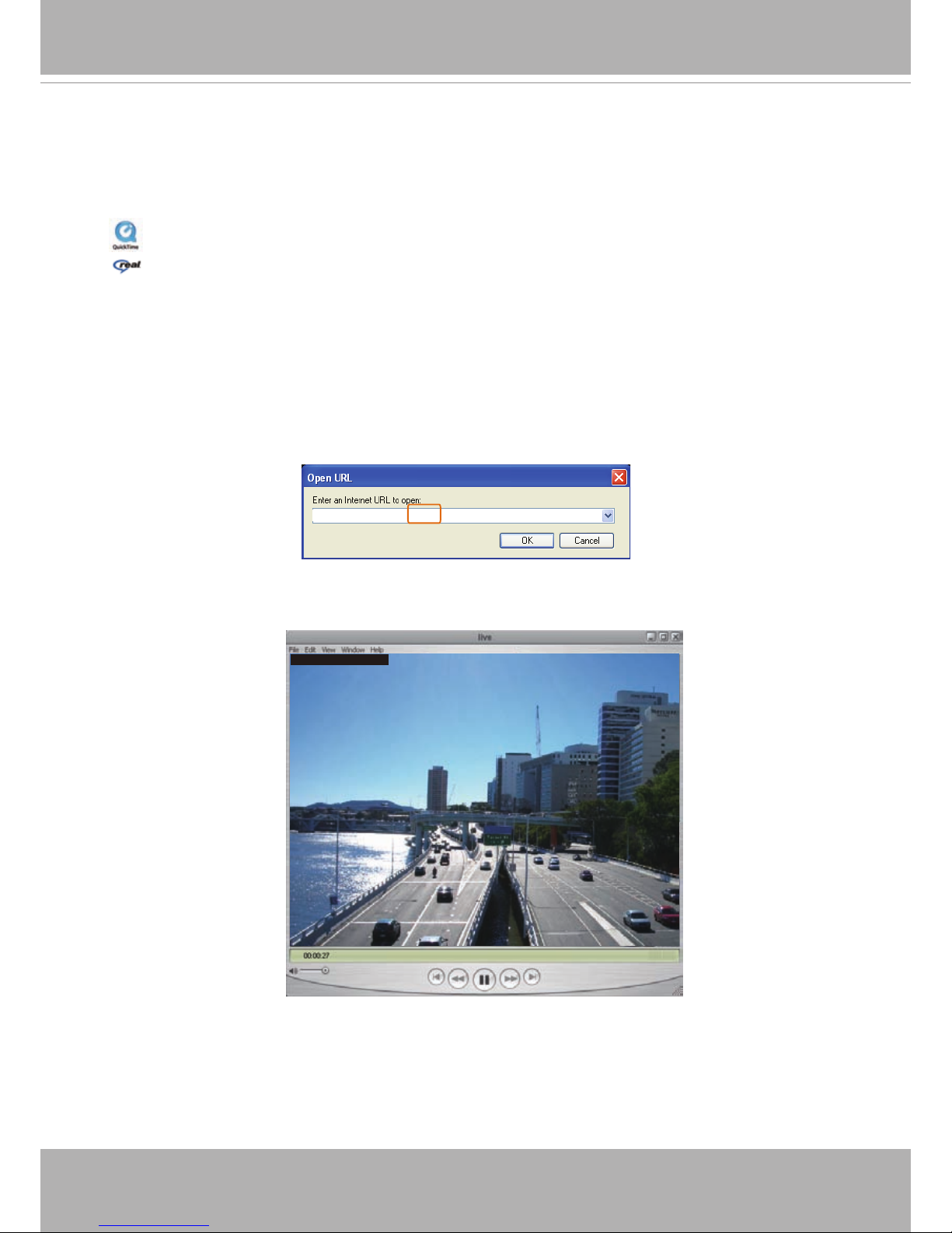
4. The live video will be displayed in your player. For more information on how to congure the
RTSP access name, please refer to RTSP Streaming on page 60 for details.
1. Launch the RTSP player.
2. Choose File > Open URL. A URL dialog box will prompt.
3. The address format is rtsp://<ip address>:<rtsp port>/<RTSP streaming access name for
stream1 or stream2>
rtsp://192.168.5.151:554/live.sdp
Video 16:38:01 2011/03/25
VIVOTEK
User's Manual - 21
Using 3GPP-compatible Mobile Devices
To view the streaming media through 3GPP-compatible mobile devices, make sure the Network
Camera can be accessed over the Internet. For more information on how to set up the Network
Camera over the Internet, please refer to Setup the Network Camera over the Internet on page
11.
To utilize this feature, please check the following settings on your Network Camera:
1. Because most players on 3GPP mobile phones do not support RTSP authentication, make
sure the authentication mode of RTSP streaming is set to disable.
For more information, please refer to RTSP Streaming on page 60.
2. As the bandwidth on 3G networks is limited, you will not be able to use a large video size.
Please set the video and audio streaming parameters as listed below.
For more information, please refer to Stream settings on page 77.
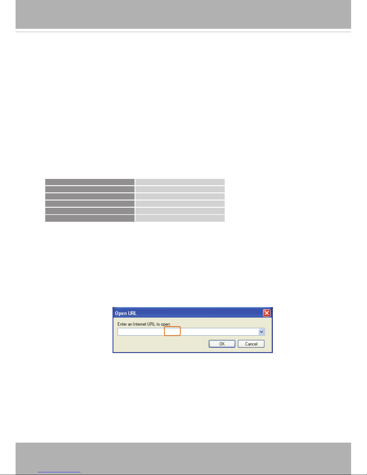
Video Mode MPEG-4
Frame size 176 x 144
Maximum frame rate 5 fps
Intra frame period 1S
Video quality (Constant bit rate) 40kbps
Audio type (GSM-AMR) 12.2kbps
3. As most ISPs and players only allow RTSP streaming through port number 554, please set
the RTSP port to 554. For more information, please refer to RTSP Streaming on page 60.
4. Launch the player on the 3GPP-compatible mobile devices (e.g., Real Player).
5. Type the following URL commands in the URL eld.
The address format is rtsp://<public ip address of your camera>:<rtsp port>/<RTSP streaming
access name for stream 3>.
For example:
rtsp://192.168.5.151:554/live.sdp
VIVOTEK
22 - User's Manual
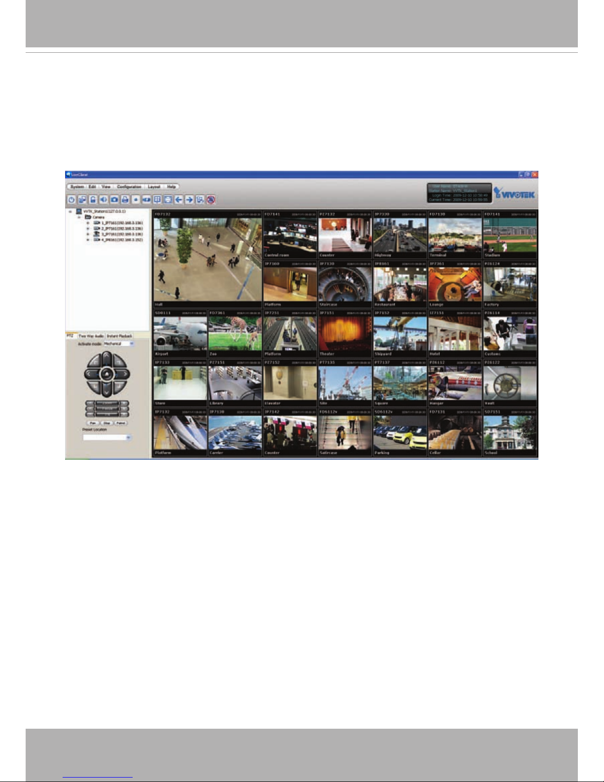
Using VIVOTEK Recording Software
The product software CD also contains recording software, allowing simultaneous monitoring
and video recording for multiple Network Cameras. Please install the recording software; then
launch the program to add the Network Camera to the Channel list. For detailed information
about how to use the recording software, please refer to the user’s manual of the software or
download it from http://www.vivotek.com.
VIVOTEK
User's Manual - 23
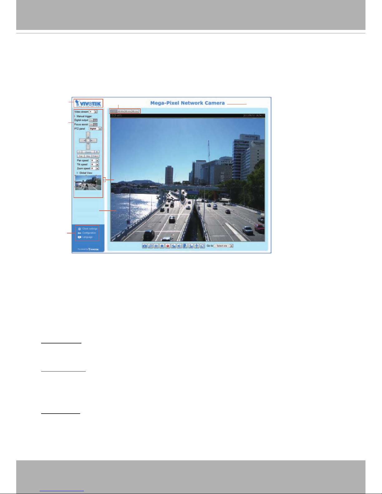
Main Page
This chapter explains the screen elements on the main page. It is composed of the following
sections: VIVOTEK INC. Logo, Host Name, Camera Control Area, Conguration Area, and Live
Video Window.
VIVOTEK INC. Logo
Click this logo to visit the VIVOTEK website.
Host Name
The host name can be customized to t your needs. For more information, please refer to System on page 29.
Camera Control Area
Video Stream: This Network Camera supports multiple streams (stream 1 and 2) simultaneously. You
can select either one for live viewing. For more information about multiple streams, please refer to page
77 for detailed information.
Manual Trigger: Click to enable/disable an event trigger manually. Please configure an event setting
before enabling this function. A total of 3 or 4 event settings can be congured. For more information
about event setting, please refer to page 85. If you want to hide this item on the homepage, please go to
the System > Homepage Layout > General settings > Customized button to deselect “show manual
trigger button”.
Digital Output: Click to turn the digital output device on or off.
VIVOTEK INC.
Logo
Camera Control
Area
Configuration
Area
Resize Buttons
Hide Button
Live View Window
Host Name
VIVOTEK
24 - User's Manual
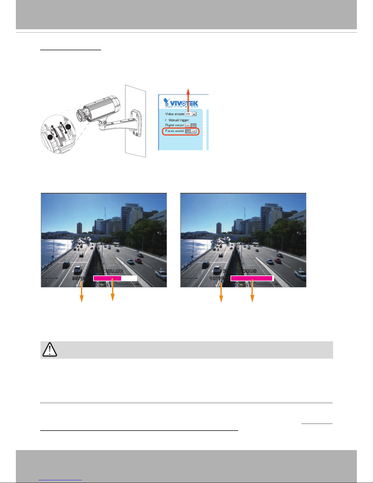
Focus Assist Button:
Follow the steps below to manually ne-tune the camera’s focus.
1. Manually adjust the zoom controller of the camera lens to x the camera’s view angle.
2. Click on the “On” button of the Focus Assist function on the homepage session with the camera to
start the focus assist function. The Live View window will automatically enter the full screen mode.
3. The oating indicator will appear at the bottom of the screen showing the calculated focus information.
While you manually adjust the camera’s focus, the numeric readings and the on-screen color bar
should fluctuate and you should find the best results when the focus value is stated as the “BEST
FOCUS.”
4. When done, tighten the zoom and focus controller bars, and then press the ESC key to leave the full-
screen mode.
5. Turn off the focus assist function by clicking the “Off” button.
You may also refer to VIVOTEK’s website for an application note on the use of this function: http://www.
vivotek.com/support/appnote.php?appcon=29&appcatagory=rmware.
Zoom
Focus
T
W
∞
N
3
4
Stream is being adjusted
FOCUS VALUE
98/107
BEST FOCUS
107/107
The color bar fluctuates according to current focus value. The color bar reaches the optimal value.
IMPORTANT!
Before using the Focus Assist function, the camera should have been stably installed and the
camera's shooting direction and view angle must be secured for a stable view. If the view is
altered, you should ne-tune the camera's zoom and focus again by turning off and restarting
the function.
VIVOTEK
User's Manual - 25
Conguration Area
Client Settings: Click this button to access the client setting page. For more information, please refer to
Client Settings on page 26.
Conguration: Click this button to access more of the conguration options provided with the Network
Camera. It is suggested that a password is applied to the Network Camera so that only the administrator
can configure the Network Camera. For more information, please refer to the description for the
Conguration menus on page 28.
Language: Click this button to choose a language for the user interface. Language options are available
in: English, Deutsch, Español, Français, Italiano,
日本語
, Português,
簡体中文
, and
繁體中文
. You can
also change a language on the Conguration page; please refer to page 28.
Hide Button
You can click the hide button to hide the control panel or display the control panel.
Resize Buttons
:
Click the Auto button, the video cell will resize automatically to t the monitor.
Click 100% is to display the original home page size.
Click 50% is to resize the home page to 50% of its original size.
Click 25% is to resize the home page to 25% of its original size.
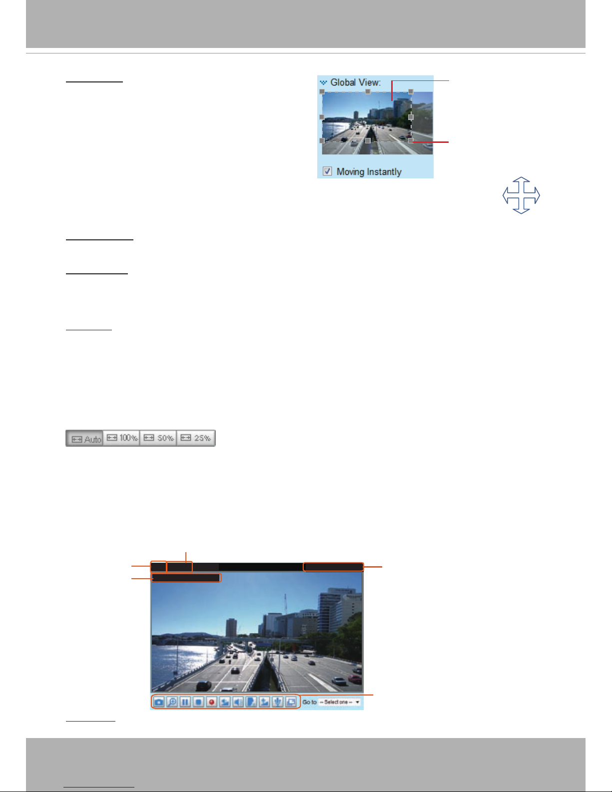
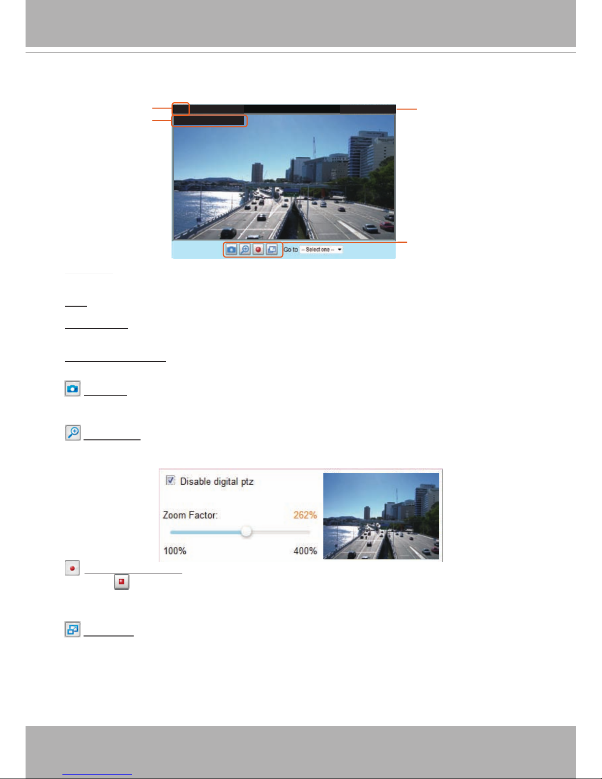
Live Video Window
■ The following window is displayed when the video mode is set to H.264 / MPEG-4:
Video Title: The video title can be congured. For more information, please refer to Video settings on
page 69.
Global View: Click on this item to display the Global
View window. The Global View window contains a full
view image (the largest frame size of the captured
video) and a oating frame (the viewing region of the
current video stream). The oating frame allows users
to control the e-PTZ function (Electronic Pan/Tilt/
Zoom). For more information about e-PTZ operation,
please refer to E-PTZ Operation on page 82. For more
information about how to set up the viewing region of
the current video stream, please refer to page 77.
Video 17:08:56 2011/03/10
Title and Time
2011/03/10 17:08:56
Time
Video and Audio Control Buttons
Video (TPC-AV)
H.264/MPEG-4 Protocol and Media Options
Video Title
The viewing region
of the current video
stream
The largest frame size
To move the current view window, place
your cursor on it and let the cursor
change to the all-direction arrow.
all-direction arrow
VIVOTEK
26 - User's Manual
H.264 / MPEG-4 Protocol and Media Options: The transmission protocol and media options for H.264 /
MPEG-4 video streaming. For further conguration, please refer to Client Settings on page 26.
Time: Display the current time. For further configuration, please refer to Media > Image > General
settings on page 69.
Title and Time: The video title and time can be stamped on the streaming video. For further conguration,
please refer to Media > Image > General settings on page 69.
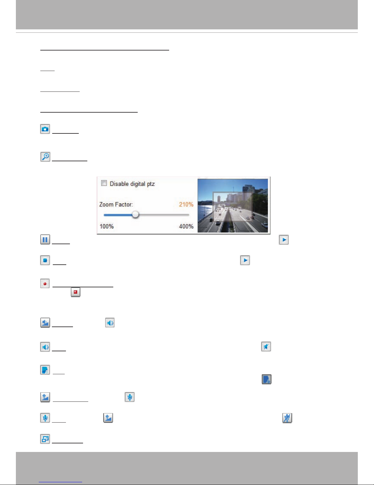
Video and Audio Control Buttons: Depending on the Network Camera model and Network Camera
conguration, some buttons may not be available.
Snapshot: Click this button to capture and save still images. The captured images will be displayed
in a pop-up window. Right-click the image and choose Save Picture As to save it in JPEG (*.jpg) or BMP
(*.bmp) format.
Digital Zoom: Click and deselect “Disable digital zoom” to enable the zoom operation. The navigation
screen indicates the part of the image being magnied. To control the zoom level, drag the slide bar. To
move to a different area you want to magnify, drag the navigation screen.
Pause: Pause the transmission of the streaming media. The button becomes the Resume button
after clicking the Pause button.
Stop: Stop the transmission of the streaming media. Click the Resume button to continue
transmission.
Start MP4 Recording: Click this button to record video clips in MP4 file format to your computer.
Press the
Stop MP4 Recording button to end recording. When you exit the web browser, video
recording stops accordingly. To specify the storage destination and le name, please refer to MP4 Saving
Options on page 27 for details.
Volume: When the Mute function is not activated, move the slider bar to adjust the volume on the
local computer.
Mute: Turn off the volume on the local computer. The button becomes the Audio On button after
clicking the Mute button.
Talk: Click this button to talk to people around the Network Camera. Audio will project from
the external speaker connected to the Network Camera. Click this button
again to end talking
transmission.
Mic Volume: When the Mute function is not activated, move the slider bar to adjust the
microphone volume on the local computer.
Mute: Turn off the Mic volume on the local computer. The button becomes the Mic On button
after clicking the Mute button.
Full Screen: Click this button to switch to full screen mode. Press the “Esc” key to switch back to normal
mode.
VIVOTEK
User's Manual - 27
■ The following window is displayed when the video mode is set to MJPEG:
Video Title: The video title can be congured. For more information, please refer to Media > Image on
page 69.
Time: Display the current time. For more information, please refer to Media > Image on page 69.
Title and Time: Video title and time can be stamped on the streaming video. For more information, please
refer to Media > Image on page 69
.
Video Control Buttons: Depending on the camera model and your current conguration, some buttons
may not be available.
Snapshot: Click this button to capture and save still images. The captured images will be displayed
in a pop-up window. Right-click the image and choose Save Picture As to save it in JPEG (*.jpg) or BMP
(*.bmp) format.
Digital Zoom: Click and uncheck “Disable digital zoom” to enable the zoom operation. The navigation
screen indicates the part of the image being magnied. To control the zoom level, drag the slider bar. To
move to a different area you want to magnify, drag the navigation screen.
Start MP4 Recording: Click this button to record video clips in MP4 file format to your computer.
Press the
Stop MP4 Recording button to end recording. When you exit the web browser, video
recording stops accordingly. To specify the storage destination and le name, please refer to MP4 Saving
Options on page 27 for details.
Full Screen: Click this button to switch to full screen mode. Press the “Esc” key to switch back to normal
mode.
Video 17:08:56 2011/03/10
Title and Time
2011/03/10 17:08:56
Time
Video (HTTP-V)
Video Title
Video Control Buttons
VIVOTEK
28 - User's Manual
Client Settings
This chapter explains how to select the stream transmission mode and saving options on the
local computer. When completed with the settings on this page, click Save on the page bottom
to enable the settings.
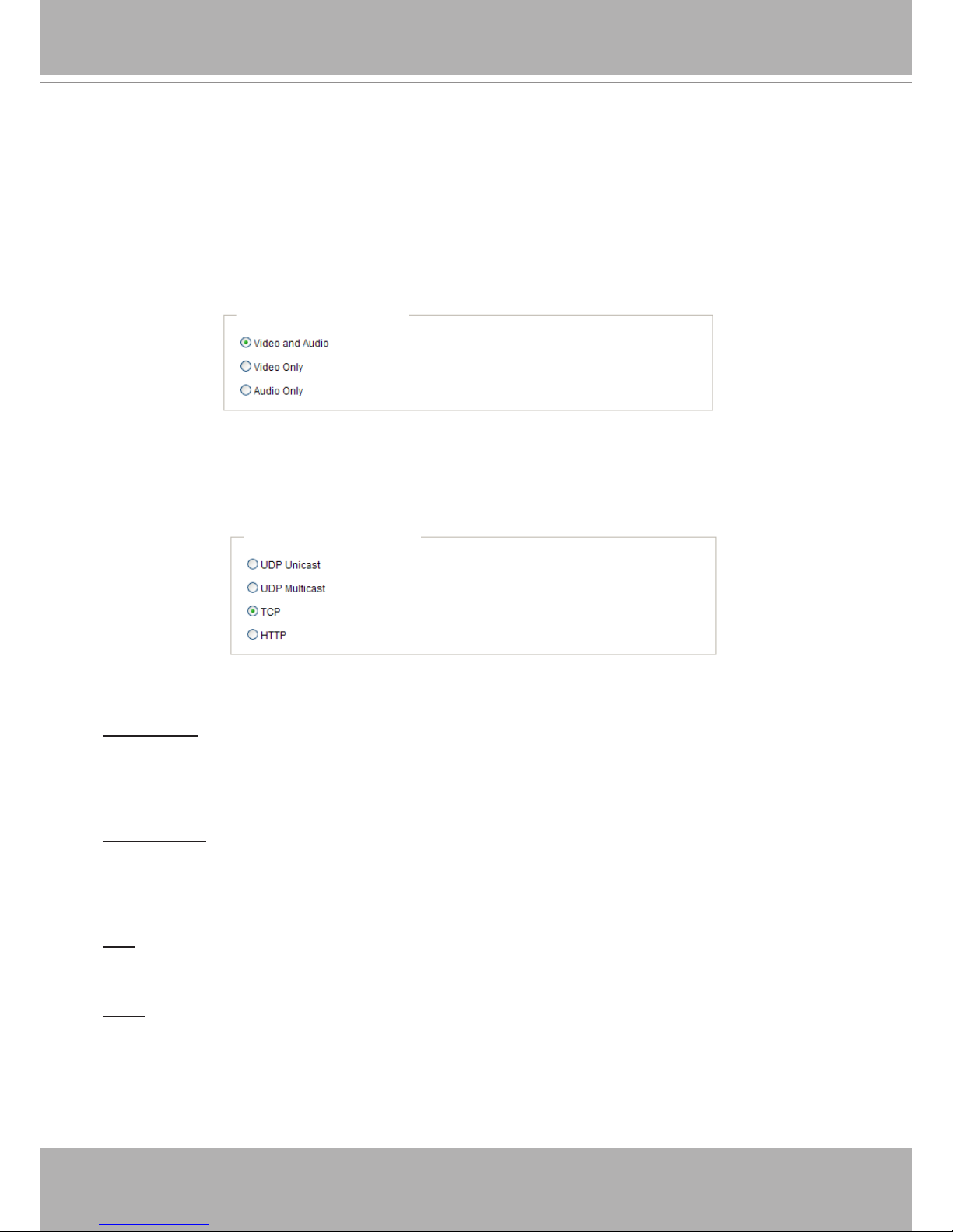
H.264 / MPEG-4 Media Options
Select to stream video or audio data or both. This is enabled only when the video mode is set to H.264 or
MPEG-4.
H.264 / MPEG-4 Protocol Options
Depending on your network environment, there are four options with the transmission protocols with
H.264 or MPEG-4 streaming:
UDP unicast: This protocol allows for more real-time audio and video streams. However, network
packets may be lost due to network burst trafc and images may be broken. Activate UDP connection
when occasions require time-sensitive responses and the video quality is less important. Note that each
unicast client connecting to the server takes up additional bandwidth and the Network Camera allows up
to ten simultaneous accesses.
UDP multicast: This protocol allows multicast-enabled routers to forward network packets to all clients
requesting streaming media. This helps to reduce the network transmission load of the Network Camera
while serving multiple clients at the same time. Note that to utilize this feature, the Network Camera must
be configured to enable multicast streaming at the same time. For more information, please refer to
RTSP Streaming on page 60.
TCP: This protocol guarantees the complete delivery of streaming data and thus provides better video
quality. The downside of this protocol is that its real-time effect is not as good as that of using the UDP
protocol.
HTTP: This protocol allows the same quality as TCP protocol without needing to open specic ports for
streaming under some network environments. Users behind a rewall can utilize this protocol to allow
camera’s streaming data to pass through.
H.264/MPEG-4 Media Options
H.264/MPEG-4 Protocol Options
VIVOTEK
User's Manual - 29
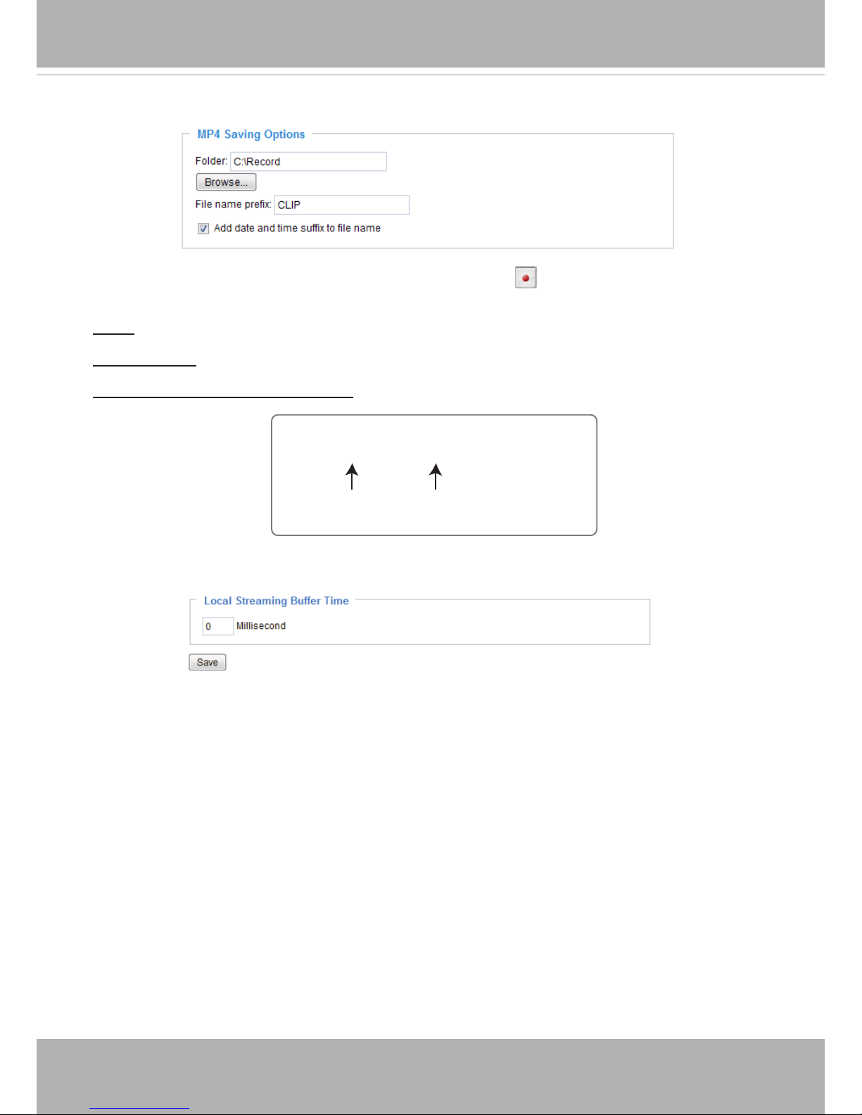
MP4 Saving Options
Users can record live video as they are watching it by clicking Start MP4 Recording on the main
page. Here, you can specify the storage destination and le name.
Folder: Specify a storage destination for the recorded video les.
File name prex: Enter the text that will be appended to the front of the video le name.
Add date and time sufx to the le name: Select this option to append the date and time to the end of the
le name.
Local Streaming Buffer Time
Due to unsteady bandwidth flow, live streaming may lag and not be very smoothly. If you enable this
option, the live streaming will be stored on the camera’s buffer area for a few seconds before being
played on the live viewing window. This helps produce a smooth live streaming. If you enter a value of
3000 milliseconds, the streaming will delay for 3 seconds.
CLIP_20110328-180853
Date and time suffix
The format is: YYYYMMDD_HHMMSS
File name prefix
VIVOTEK
30 - User's Manual
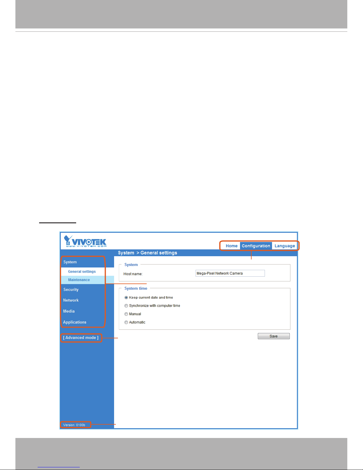
Conguration
Click Configuration on the main page to enter the camera setting pages. Note that only
Administrators can access the conguration page.
VIVOTEK offers an easy-to-use user interface that helps you set up your network camera with
minimal effort. To simplify the setting procedure, two types of user interfaces are available:
Advanced Mode for professional users and Basic Mode for entry-level users. Some advanced
functions (PTZ/ Event/ Recording/ Local storage) are not displayed in Basic Mode.
If you want to set up advanced functions, please click on [Advanced Mode] at the bottom of the
conguration list to switch to Advanced Mode.
In order to simplify the user interface, detailed information will be hidden unless you click on the
function item. When you click on the rst sub-item, the detailed information for the rst sub-item
will be displayed; when you click on the second sub-item, the detailed information for the second
sub-item will be displayed and that of the rst sub-item will be hidden.
The following is the interface of the Basic Mode and the Advanced Mode:
Basic Mode
Configuration List
Click to switch to Advanced Mode
Navigation Area
Firmware Version
 Loading...