

Vivotek IP8335H Installation
720p HD WDR Pro IP67
Quick Installation Guide
English
繁中
簡中
日本語
Français
Español Português
Deutsch
Italiano
Türkçe
Polski
Русский
Česky Svenska
IP8335H
This guide describes the basic functions of IP8335H. More
details can be found in the User Manual.
IP Surveillance
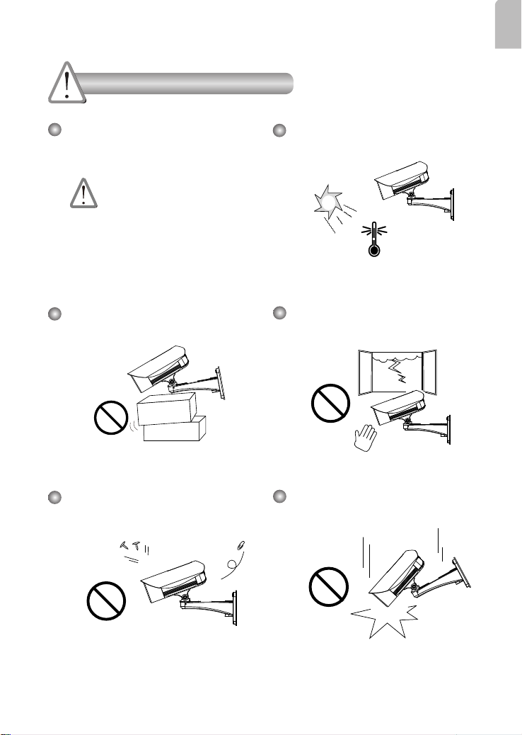
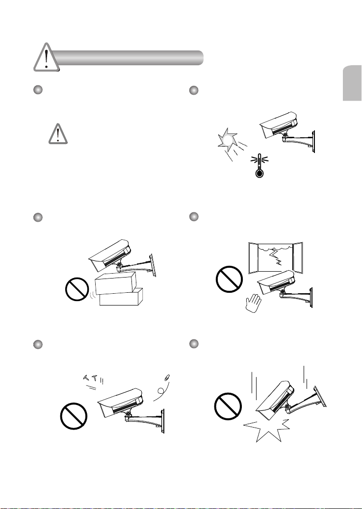
Warning Before Installation
English
Power off the Network Camera as
soon as smoke or unusual odors are
detected.
Contact your distributor in the
event of occurrence.
Do not place the Network Camera on
unsteady surfaces.
Do not insert sharp or tiny objects
into the Network Camera.
Refer to your user's manual for the
operating temperature.
Do not touch the Network Camera
during a lightning storm.
Do not drop the Network Camera.
EN-1
1
5
1
0
0
0
0
2
0
2
G
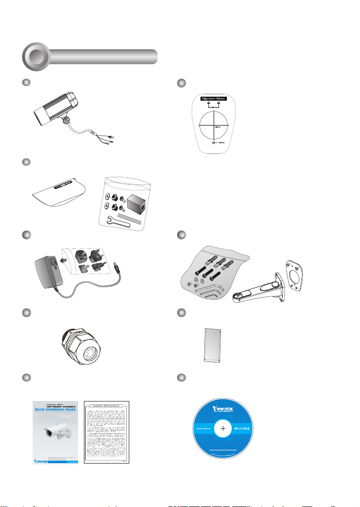
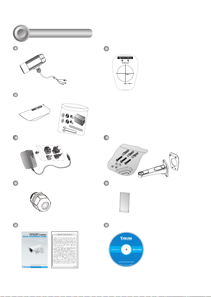
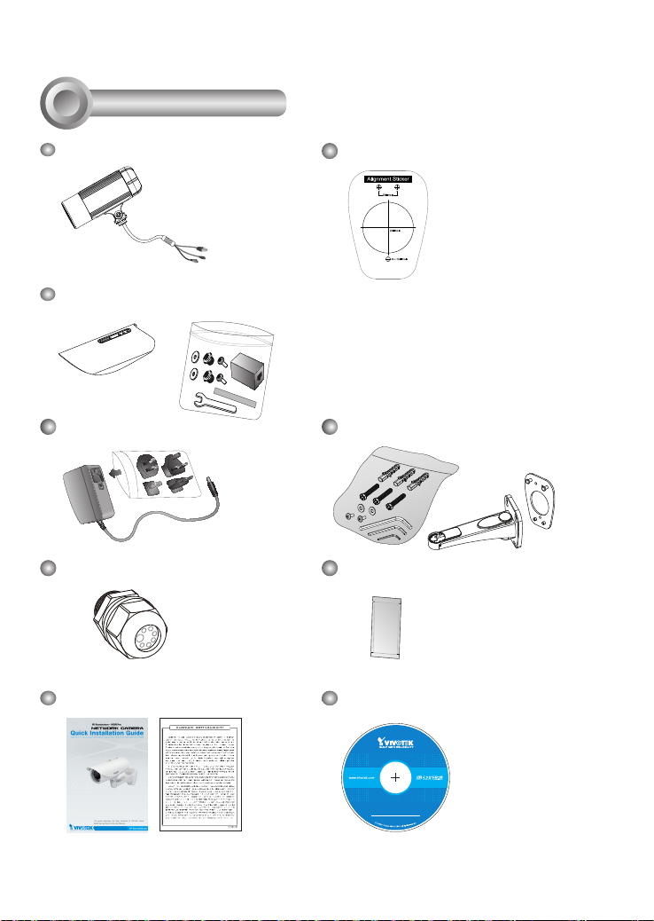
Package Contents
IP8335H
Alignment Sticker
Sun Shield
Wrench / RJ45 Female/Female Coupler / Double-sided Tape / Screws
Power Adapter
Waterproof Connector (for backup
Wall Mount Bracket
Moisture Absorber
use)
Quick Installation Guide /
Warranty Card
Software CD
EN-2
2
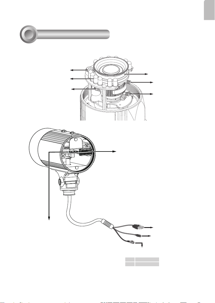
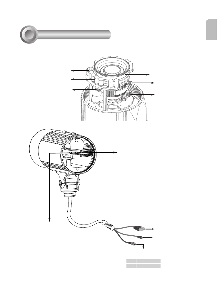
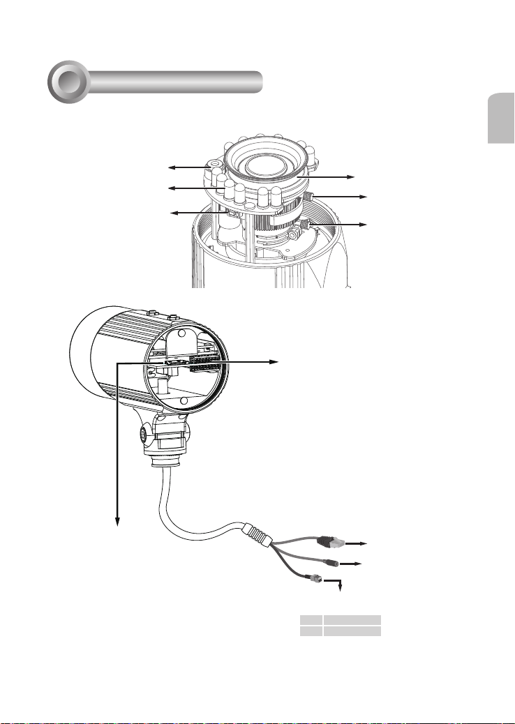
Physical Description
English
Light Sensor
IR LED
Reset Button
Micrso SD/SDHC
Card Slot
Lens
Focus Controller
Zoom Controller
General I/O
Terminal Block
Ethernet 10/100
RJ45 Plug
Power Cord Socket
Alternate AC Power Source
+ AC 24V +
- AC 24V -
EN-3

3
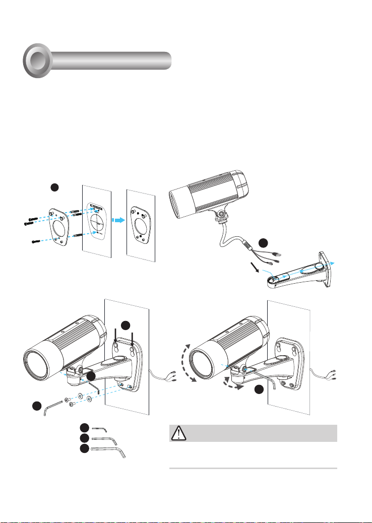
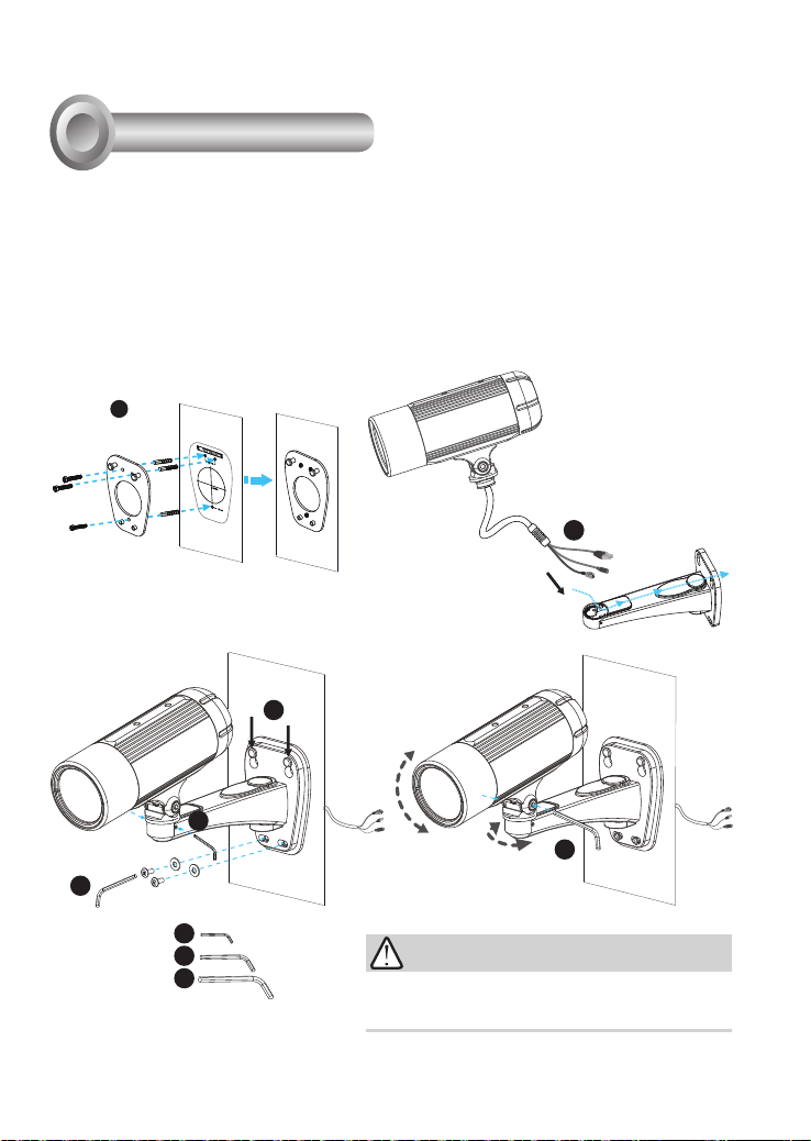
Hardware Installation
1. Attach the alignment sticker to the wall. Drill three holes into the wall. Then hammer the supplied
plastic anchors into the holes and secure the plate with supplied screws.
2. Feed the cables through the front opening of the wall mount bracket. (If you want to use external
devices such as sensors and alarms, please refer to the assembling steps on the next page.)
3. Hang the wall mount bracket on the plate.
4. Fix the Network Camera on the wall mount bracket with two screws on both sides.
5. Secure the wall mount bracket with the supplied screws.
6. Adjust the angle of the wall mount bracket to aim at the shooting area.
1
2
3
4
6
5
4
5
6
IMPORTANT!
The supplied L-type hex key wrenches are exclusively
designed to match each screw. In case you will need to adjust
the lens later, do not discard the wrenches.
EN-4
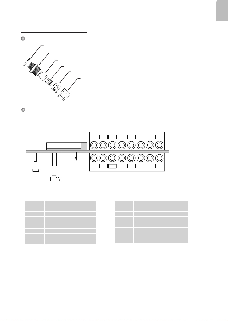
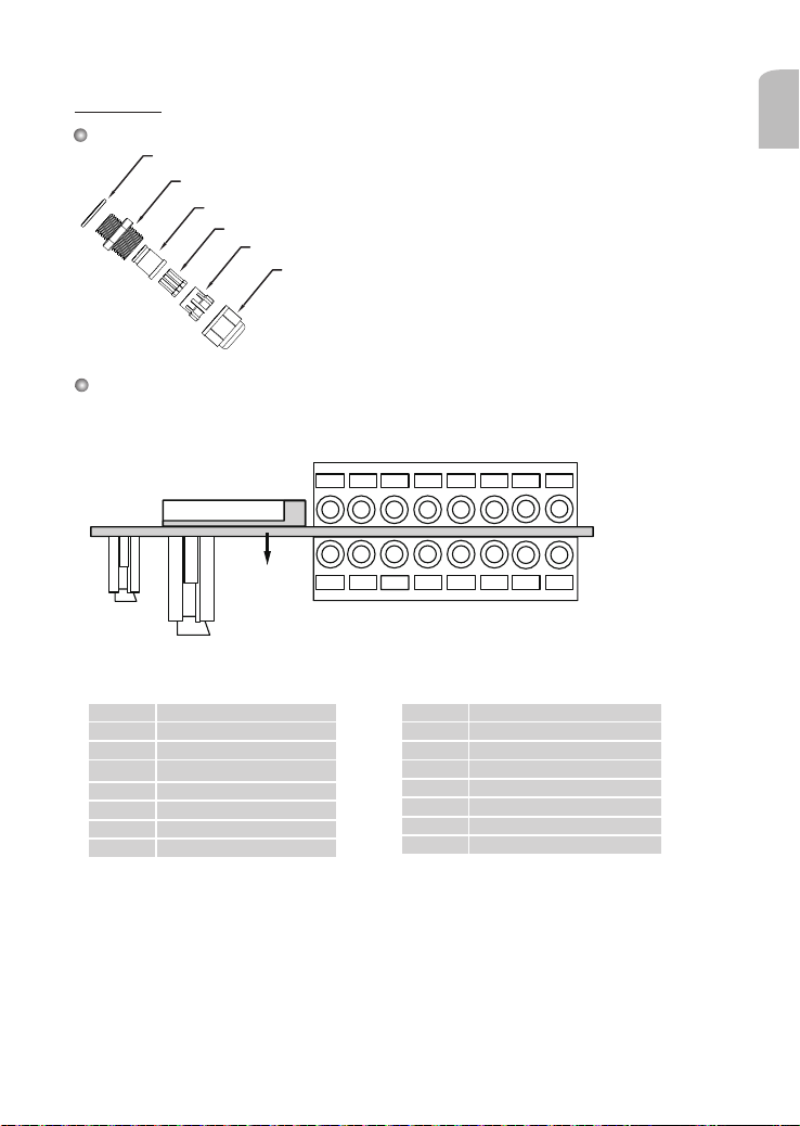
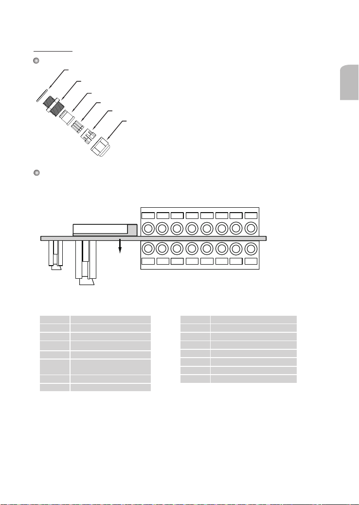
Waterproof Connector
Components of the Waterproof Connector
Rubber (A)
Screw Nut (B)
Seal (C)
Seals (D)
Housing (E)
Sealing Nut (F)
Pin Denitions
The terminal block is accessible when the rear cover is opened.
English
87654321
Micro SD Socket
PCB
Ethernet
Power
J3
1 Digital Input 1: DI1
2 Digital Input: - (Ground)
3 RS485 +
4 RS485 5 AUDIO_GND
6 AUDIO_IN: Ext_MIC_IN
7 AUDIO_GND
8 AUDIO_OUT
J7
* Vmax.: 40V DC, Imax.: 400mA.
** Power output, 12V DC: max. load is 50mA.
EN-5
J3
J7
87654321
1 N/C
2 N/C
3 DO- *
4 DO+ **
5 Digital Input: - (Ground)
6 Digital Input 3: DI3
7 Digital Input: - (Ground)
8 Digital Input 2: DI2
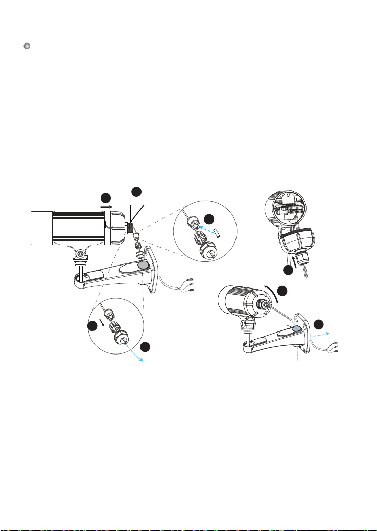
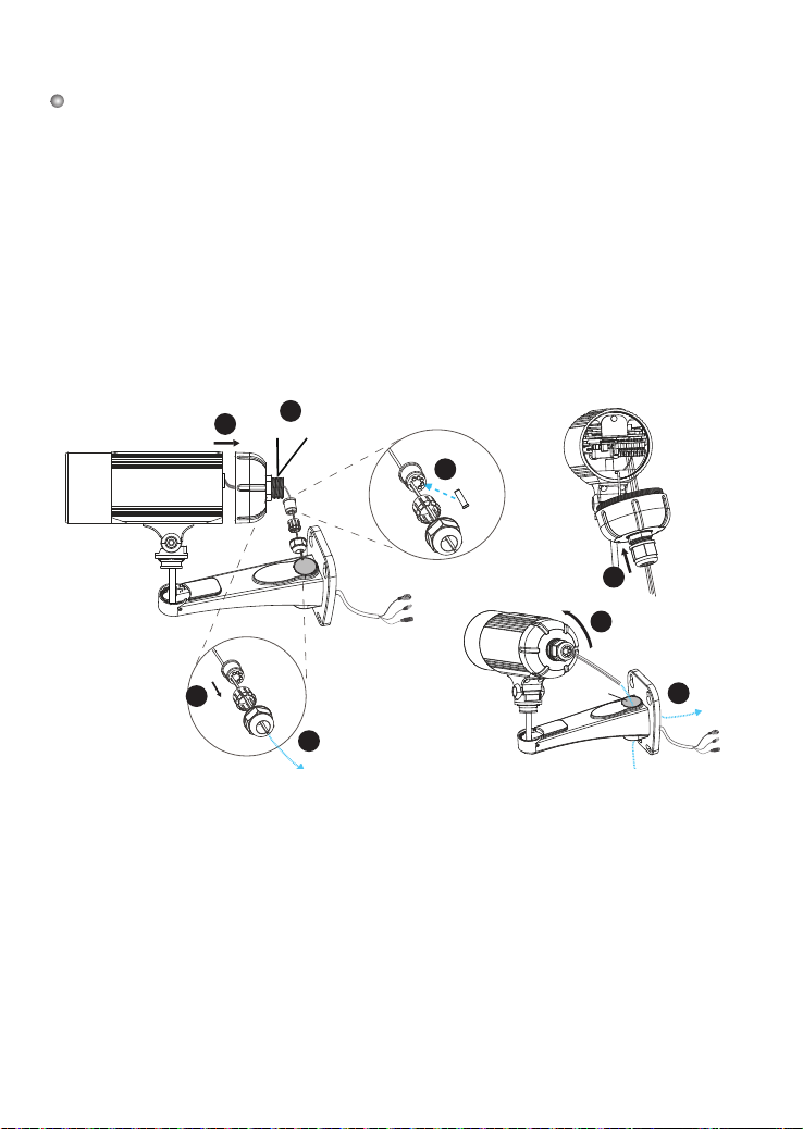
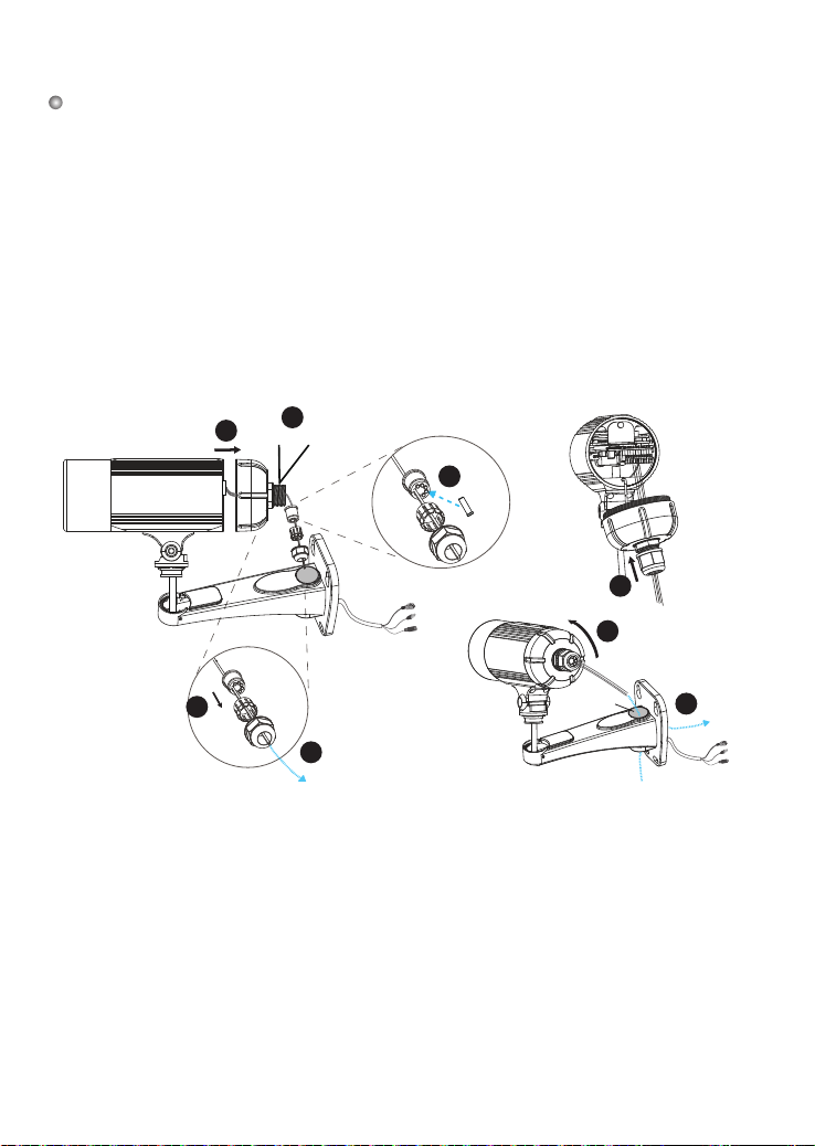
Assembling Steps
1. Disassemble the components of the waterproof connector into part (A) ~ (F) as shown above.
2. Remove the rubber stopper from the bottom of the Network Camera and secure the rubber (A)
and screw nut (B) tightly.
3. Open the back cover of the Network Camera.
4. If you have external devices such as sensors and alarms, feed the cables through the waterproof
connector (F --> E --> C --> A+B) as the illustration shown below. Then refer to the pin denition
to connect them to the general I/O terminal block. Note: The recommended cable gauge is 2.0 ~ 2.8
mm.
5. Push the seal (C) into the housing (E).
6. Insert the seals (D) into the empty holes on the seal (C) to avoid moisture.
7. Secure the sealing nut (F) tightly.
8. Tighten the back cover.
9. Remove rubber (G) and feed the cables through the wall mount bracket.
3
2
(A)+(B)
(E)
(F)
(C)
(C)
6
(D)
(F)
7
8
(C)
5
(E)
(F)
4
(G)
9
EN-6
4
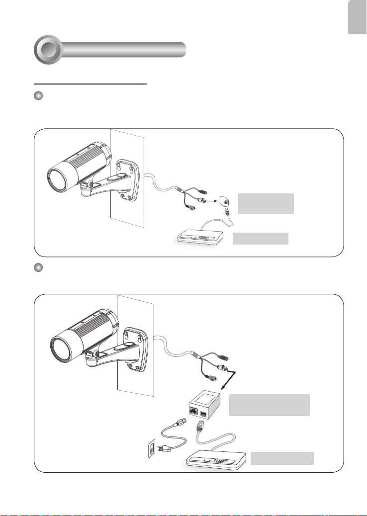
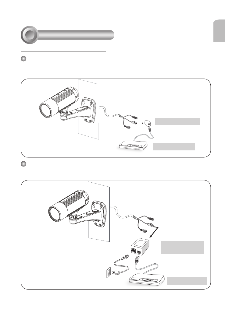
Network Deployment
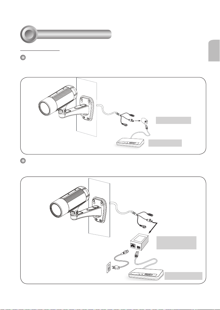
Power over Ethernet (PoE)
When using a PoE-enabled switch
The Network Camera is PoE-compliant, allowing transmission of power and data via a single
Ethernet cable. Follow the below illustration to connect the Network Camera to a PoE-enabled
switch via Ethernet cable.
RJ45 Female/
Female Coupler
LINK
POWER
COLLISION
RECEIVE
1
2
PARTITION
3
4
5
PoE Switch
When using a non-PoE switch
Use a PoE power injector (optional) to connect between the Network Camera and a non-PoE
switch.
English
EN-7
PoE Power Injector
(optional)
Non-PoE Switch
LINK
POWER
COLLISION
RECEIVE
1
2
PARTITION
3
4
5

Network Camera
Model No: IP8335H
Made in Taiwan
This device complies with part 15 of the FCC rules. Operation is subject to the following two conditions:
(1)This device may not cause harmful interference, and
(2) this device must accept any interference received, including interference that may cause undesired operation.
Pat. 6,930,709
MAC:0002D1730202
Ro HS
5
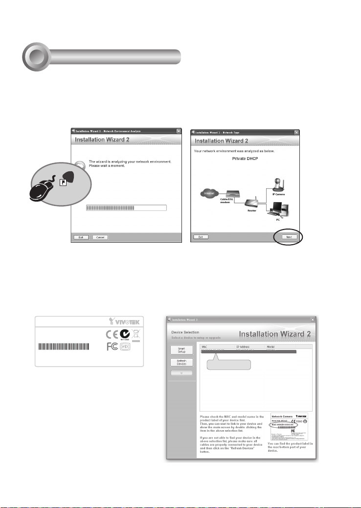
Assigning an IP Address
1. Install "Installation Wizard 2" from the Software Utility directory on the software CD.
2. The program will conduct an analysis of your network environment. After your network
is analyzed, please click on the "Next" button to continue the program.
IW
2
Installation
Wizard 2
3. The program will search for VIVOTEK Video Receivers, Video Servers, and Network
Cameras on the same LAN.
4. After searching, the main installer window will pop up. Click on the MAC that matches
the one on the product label to connect to the Network Camera via Internet Explorer.
00-02-D1-73-02-02 192.168.5.151 IP8335H
0002D1730202
EN-8
6
T
W
∞
N
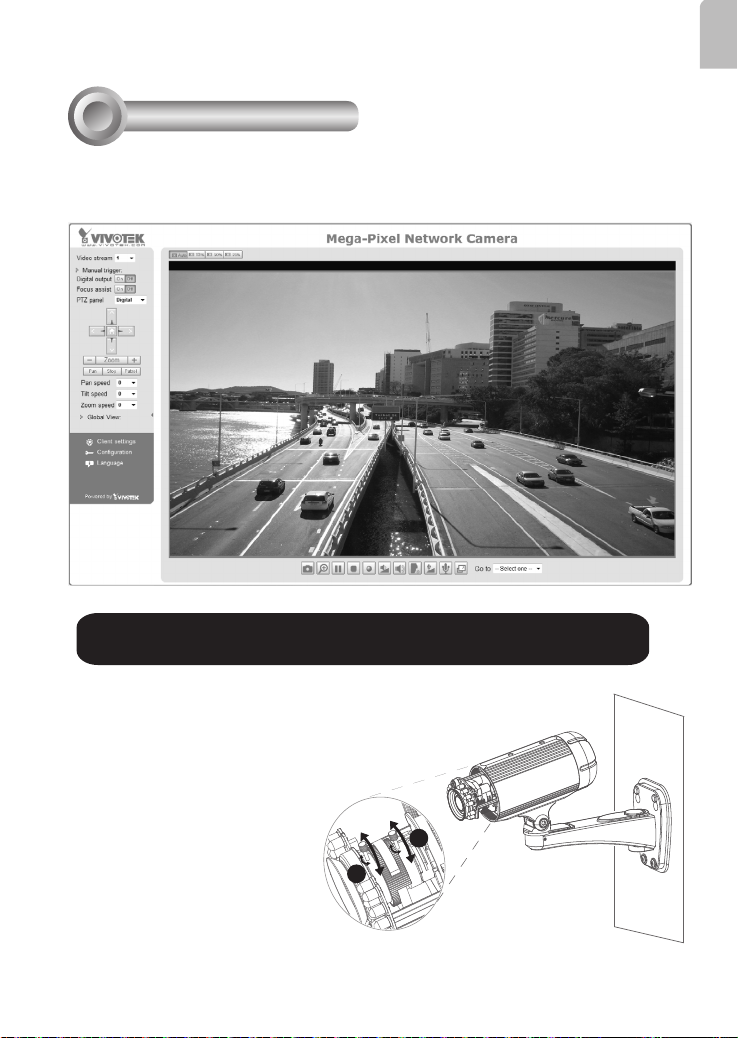
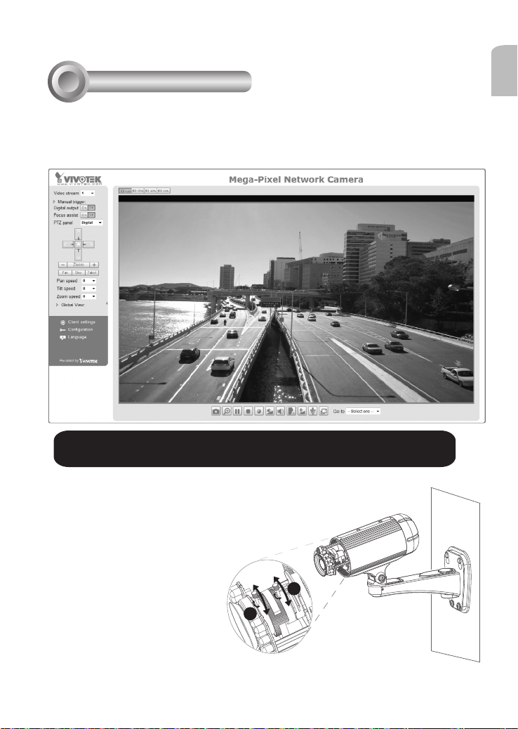
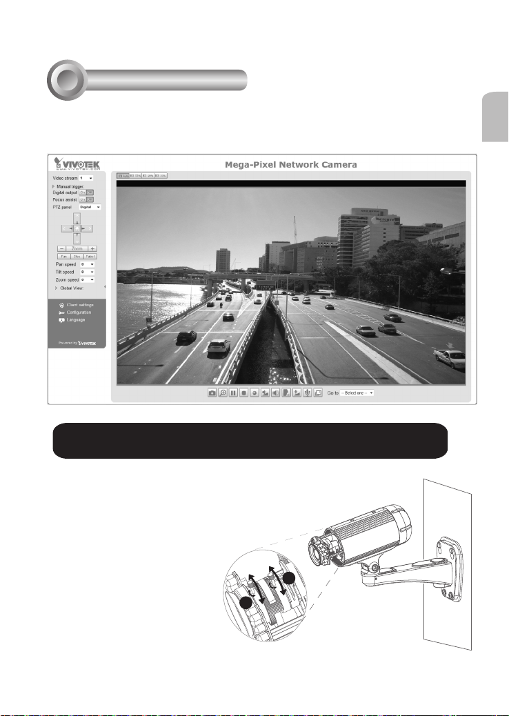
Ready to Use
1. Access the Network Camera from the LAN.
2. Retrieve live video through a web browser or recording software.
English
For further setup, please refer to the user's manual on the software CD.
3. Unscrew the zoom controller to adjust the
zoom factor. Upon completion, tighten the
zoom controller.
4. Unscrew the focus controller to adjust the
focus range. Upon completion, tighten the
focus controller.
3
4
EN-9
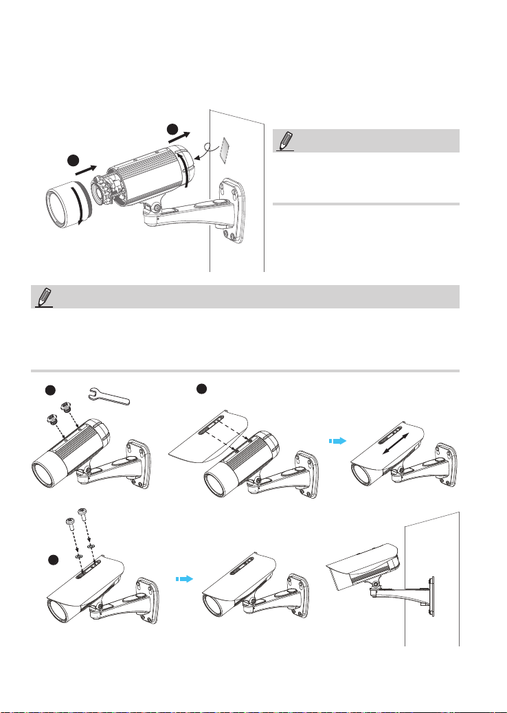
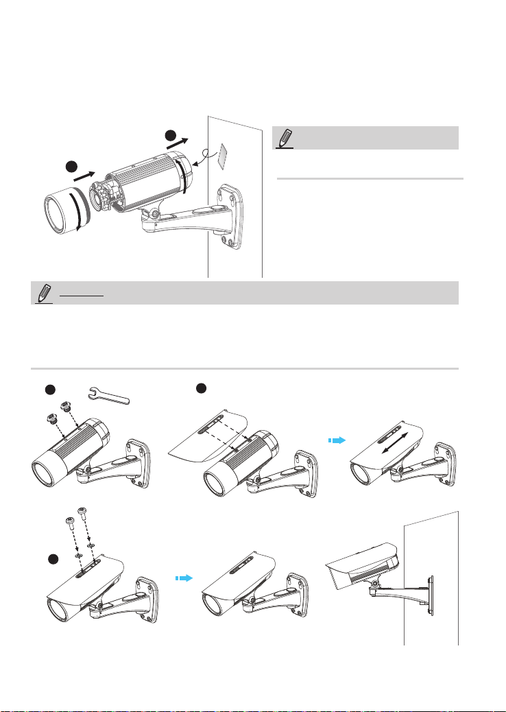
5. Tighten the lens cover.
6. Replace the moisture absorber with a new one if you open the back cover during the
installation procedure.
6
5
NOTE:
If you want to use the supplied sun shield for outdoor environments, please follow the steps below to
install:
NOTE:
Please tear down the aluminum foil vacuum bag
and take out the moisture absorber, then attach the
moisture absorber with the supplied double-sided
tape.
1. Tighten the two supplied hex standoffs.
2. Attach the supplied sun shield to the Network Camera and slide it to the desired position.
3. Fix the sun shield with the supplied two screws.
1
2
3
EN-10

安裝前應注意事項
中文(繁體)
如果發現網路攝影機出現煙霧或聞到
異味時,請立即關閉電源。
當這種情況發生的時候,請聯絡
您的經銷商。
請勿將網路攝影機擺放在不穩定的物
體上。
請勿將任何物件插入網路攝影機,例
如細針。
有關操作時的溫度,請參閱使用者說明
書。
閃電時,請勿碰觸網路攝影機。
請勿讓網路攝影機掉落地面。
TC-11
檢查包裝內容物
5
1
0
0
0
0
2
0
2
G
1
IP8335H
校準貼紙
遮陽罩
扳手 / RJ45 母對母連接器 (female/female coupler) / 雙面膠 / 螺絲
電源供應器
防水接頭(備用)
壁掛腳架
防潮包
快速安裝手冊 / 產品保固卡
軟體光碟
TC-12
實體外觀說明
2
中文(繁體)
光線感應器
紅外線 LED 燈
重設按鈕
SD/SDHC卡插槽
鏡頭
對焦控制桿
變焦控制桿
一般 I/O 端子接線排
乙太網路10/100
RJ45插孔
電源線插孔
TC-13
交流電源
+ AC 24V +
- AC 24V -
3
硬體架設
1. 校準貼紙貼至牆面上。在牆面上鑽三個孔洞。然後將塑膠錨釘敲入導孔中,並以隨附的螺絲鎖附
掛版。
2. 將纜線穿過壁掛腳架前端開口。(如欲外接諸如感應器或警報等裝置,請參考下頁的組裝步驟。)
3. 將腳架掛於掛版上。
4. 以兩顆螺絲將網路攝影機固定在牆壁架設支架的兩側上。
5. 以隨附的螺絲固定牆壁架設支架。
6. 調整腳架的方向,瞄準欲拍攝的區域。
1
2
3
4
6
5
4
5
6
隨附的L型六角扳手是專為旋緊兩顆螺絲所設計的。若您稍後需
要調整鏡頭,請勿丟棄扳手。
注意!
TC-14
防水接頭
防水接頭組件
橡膠 (A)
螺母 (B))
密封塞 (C)
針腳定義
開啟後蓋即可使用端子台。
中文(繁體)
密封塞條 (D)
外罩 (E)
密封螺母 (F)
87654321
Micro SD插槽
印刷電路板
乙太網路
電源
J3
數位輸入1:DI1
1
數位輸入:- (接地)
2
3 RS485 +
4 RS485 5 AUDIO_GND
6 AUDIO_IN: Ext_MIC_IN
7 AUDIO_GND
8 AUDIO_OUT
* Vmax.:40V DC、Imax:400mA
** 電源輸出、12V DC:最大負載為50mA
TC-15
J7
1
2
3 DO- *
4 DO+ **
5
6
7
8
J3
J7
87654321
無
無
數位輸入:- (接地)
數位輸入3:DI3
數位輸入:- (接地)
數位輸入2:DI2
組裝步驟
1. 如上所示,將防水接頭組件拆卸成(A) ~ (F)。
2. 取下網路攝影機底部的橡膠固定塞,並牢牢固定橡膠(A)及螺帽(B)。
3. 打開網路攝影機的背蓋。
4. 如欲外接諸如感應器或警報等裝置,如下圖所示,請將纜線穿過壁掛腳架及防水接頭 (E --> D --> B
--> A)。接著參照針腳定義,從一般 I/O 端子接線排進行接線。注意:建議使用2.0~2.8mm的纜線。
5. 將密封塞(C)推入外罩(E)。
6. 將密封塞條(D)塞入密封塞(C)上空的孔中以確實杜絕水氣。
7. 鎖緊密封螺母(F)。
8. 旋緊後方護蓋。
9. 取下橡膠 (G),並將纜線穿過牆壁架設支架。
(F)
2
(A)+(B)
(E)
(F)
(C)
6
(C)
4
(D)
(G)
(F)
7
8
9
3
(C)
5
(E)
TC-16
網路連線
4
使用乙太網路供電(PoE)的連接方式
當使用支援PoE的交換器時
此網路攝影機符合乙太網路供電(PoE)標準,可利用乙太網路纜線來傳輸電源及資料。請參閱下
圖,利用乙太網路纜線將攝影機連接到支援乙太網路供電功能的交換器。
RJ45 母對母連接器
LINK
POWER
COLLISION
RECEIVE
1
2
PARTITION
3
4
5
支援PoE之交換器
當使用不支援PoE的交換器時
請另外購買PoE injector來連接攝影機與不支援PoE的交換器。
中文(繁體)
TC-17
PoE injector
(選購)
LINK
POWER
COLLISION
RECEIVE
1
2
PARTITION
3
4
5
不支援PoE之交換器
Network Camera
Model No: IP8335H
Made in Taiwan
This device complies with part 15 of the FCC rules. Operation is subject to the following two conditions:
(1)This device may not cause harmful interference, and
(2) this device must accept any interference received, including interference that may cause undesired operation.
Pat. 6,930,709
MAC:0002D1730202
Ro HS
分配 IP 位址
5
1. 自隨附軟體光碟上的「Software Utility」目錄下,執行「安裝精靈 2」(Installation
Wizard 2)。
2. 安裝程式會先對您的網路環境進行分析,在分析過您的網路之後,請按「下一步」按
鈕,繼續執行安裝程式。
IW
2
Installation
Wizard 2
3. 安裝程式會搜尋在相同區域網路上的VIVOTEK影音解碼器、影音伺服器或者網路攝影
機。
4. 主安裝程式視窗會在短暫搜尋後彈出。在與攝影機標籤上所列者一致、或與包裝盒標
籤上序號一致的MAC位址上按兩下,以開啟網路攝影機的瀏覽器會話視窗。
00-02-D1-73-02-02 192.168.5.151 IP8335H
0002D1730202
TC-18
準備使用
T
W
∞
N
6
1. 會出現如下圖所示的網路攝影機瀏覽器會話視窗。
2. 您應該可以從您的攝影機看到現場影像。您也可以從軟體光碟中,將32個頻道的錄影
軟體,安裝在由多部攝影機組成的部署環境中。若想瞭解其安裝細節,請參考其相關
文件。
有關進一步的設定,請參閱軟體CD上的使用手冊。
中文(繁體)
3. 將變焦控制桿調鬆來調整變焦倍數。調整
完成後,再將變焦控制桿轉緊。
4. 將對焦控制桿調鬆來調整對焦範圍。調整
完成後,再將對焦控制桿轉緊。
3
4
TC-19
5. 旋緊鏡頭蓋。
6. 若您在安裝過程中開啟背蓋,請更換新的防潮包。
6
5
注意!
請撕開鋁箔真空袋並取出防潮包,然後用隨附的雙
面膠黏貼防潮包。
注意事項
如果要在室外環境使用隨附的遮陽罩,請遵照下列步驟進行安裝:
1. 鎖緊所附的兩顆螺絲。
2. 將隨附的遮陽罩裝至「網路攝影機」上,然後推移至所要的位置。
3. 以隨附的兩顆螺絲固定遮陽罩。
1
2
3
TC-20
安装警告
如果网络摄像头冒烟或有异常气味,
请立即关闭。
如果发生上述情况请联系您的经
销商。
切勿将网络摄像头放置在不稳定的表
面上。
切勿在网络摄像头中插入任何物体,
如针状物等。
工作温度请参考用户手册。
中文(简体)
闪电时不要接触网络摄像头。
切勿使网络摄像头坠落。
SC-21
1
5
1
0
0
0
0
2
0
2
G
检查包装内容
IP8335H
遮光板
扳手 / RJ45母/母接头 / 双面胶带 / 螺丝
电源适配器
防水接头(备用)
校正贴纸
壁挂脚架
防潮包
快速安装向导 / 保修卡
软件 CD
SC-22
2
物理描述
中文(简体)
光线传感器
红外线 LED
重置按鈕
SD/SDHC卡插槽
镜头
焦点控制器
缩放控制器
标准 I/O 接线端子
以太网络10/100
RJ45插孔
电源线插槽
SC-23
备用交流电源
+ AC 24V +
- AC 24V -
3
硬件安装
1. 将校正贴纸固定在墙壁上。在墙面上钻三个孔洞。然后将塑胶锚钉敲入导孔中,并以随附的螺丝锁
附挂版。
2. 将缆线穿过壁挂脚架前端开口。(如欲外接诸如感应器或警报等装置,请参考下页的组装步骤)
3. 将脚架挂于挂版上。
4. 以两颗螺丝将网络摄影机固定在墙壁架设支架的两侧上。
5. 以随附的螺丝固定墙壁架设支架。
6. 调整脚架的方向,瞄准欲拍摄的区域。
1
2
3
4
6
5
4
5
6
注意!
随附的L型六角扳手是专为旋紧两颗螺丝所设计的。若您稍后需
要调整镜头,请勿丢弃扳手。
SC-24
防水接头
防水接头组件
橡胶 (A)
螺母 (B)
密封塞 (C)
密封塞条 (D)
外罩 (E)
针脚定义
当后盖打开时,可接触到接线板。
中文(简体)
密封螺母 (F)
87654321
Micro sd 卡插槽
PCB
以太网
电源
J3
1
数字输入1:DI1
2
数字输入:- (接地)
3 RS485 +
4 RS485 5
音频_接地
音频_输入:外部_麦克风_
6
输入
7
音频_接地
8
音频_输出
*电压:40V 直流,上限:400毫安
**电源输出,12V 直流:最大负载为50毫安
SC-25
J7
1 N/C
2 N/C
3 DO- *
4 DO+ **
5
6
7
8
J3
J7
87654321
数字输入:- (接地)
数字输入3:DI3
数字输入:- (接地)
数字输入2:DI2
组装步骤
1. 如上所示,将防水接头组件拆卸成(A) ~ (F)。
2. 取下网络摄影机底部的橡胶固定塞,并牢牢固定橡胶(A)及螺帽(B)。
3. 打开网路摄影机的背盖。
4. 如欲外接诸如感应器或警报等装置,如下图所示,请将缆线穿过壁挂脚架及防水接头(E --> D --> B
--> A)。接着参照针脚定义,从一般I/O端子接线排进行接线。注意:建议使用2.0~2.8mm的缆线。
5. 将密封塞(C)推入外罩(E)。
6. 将密封塞条(D)塞入密封塞(C)上空的孔中以确实杜绝水气。
7. 锁紧密封螺母(F)。
8. 旋紧后方护盖。
9. 取下橡胶 (G),并将缆线穿过墙壁架设支架。
(F)
2
(A)+(B)
(E)
(F)
(C)
6
(C)
4
(D)
(G)
(F)
7
8
9
3
(C)
5
(E)
SC-26
4
网络连线
以太网供电(PoE)
使用支持PoE的交换机时
该摄像头支持PoE,允许电力和数据通过以太网线缆进行传输。参阅下图,通过以太网线缆将摄像
头与PoE交换机相连接。
RJ45母/母接头
LINK
POWER
COLLISION
RECEIVE
1
2
PARTITION
3
4
5
PoE交换机
使用非PoE交换机时
使用PoE馈电器(可选)连接摄像头和非PoE交换机。
中文(简体)
SC-27
PoE馈电器
(可选)
LINK
POWER
COLLISION
RECEIVE
1
2
PARTITION
3
4
5
非PoE交换机

Network Camera
Model No: IP8335H
Made in Taiwan
This device complies with part 15 of the FCC rules. Operation is subject to the following two conditions:
(1)This device may not cause harmful interference, and
(2) this device must accept any interference received, including interference that may cause undesired operation.
Pat. 6,930,709
MAC:0002D1730202
Ro HS
5
分配 IP 地址
1. 运行软件 CD 中 Software Utility(软件实用工具)目录下的“安装向导”。
2. 程序将会对您的网络环境进行分析。分析完网络后,请单击“下一步”按钮以继续运
行程序。
IW
2
Installation
Wizard 2
3. 程序将搜索同一局域网中的VIVOTEK视频接收器、视频服务器或网络摄像头。
4. 在简易检索后,将弹出主要的安装窗口。双击与摄影机标签上标记的地址相符的MAC
地址或包装箱标签上的序列号,以打开带网络摄像机的浏览器會話視窗。
00-02-D1-73-02-02 192.168.5.151 IP8335H
0002D1730202
SC-28
6
T
W
∞
N
准备使用
1. 带网络摄像机的浏览器会话将提示如下内容。
2. 您应能从您的摄影机中观看到现场视频。对于一个部署了多个摄影机的系统,您还应
安装软件CD中的32通道录影软件。如需了解其详细的安装信息,敬请参见相关文件。
有关摄像头配置的更多信息,请参阅软件CD上的用户指南。
中文(简体)
3. 拧 松缩放 控 制器以 调 整缩放 倍 数。完 成
后,拧紧缩放控制器。
4. 拧 松焦点 控 制器以 调 整焦距 范 围。完 成
后,拧紧焦点控制器。
3
4
SC-29
 Loading...