

IP816A-LPC-v2
License Plate Capturing Solution
Highway & Street
Installation Guide
Rev. 1.0
Document part no.: 625041100G
Ordering part no.:
IP816A-LPC-v2 (Highway): 199002900G
IP816A-LPC-v2 (Street): 199002800G
IP Surveillance
CAUTION:
TO REDUCE RISK OF FIRE OR ELECTRIC SHOCK, DO NOT REMOVE COVER.
NO USER SERVICEABLE PARTS INSIDE.
REFER SERVICING TO QUALIFIED SERVICE PERSONNEL.
UNPACKING:
Unpack carefully. Electronic components can be damaged if improperly handled or
dropped. If an item appears damaged in shipment, place it properly in its carton and
notify the shipper.
IMPORTANT!:
1. Read and follow Instructions: All operating and user instructions should be read and
followed before the unit is to be operated.
2. Electrical Connections: Only a qualied electrician is allowed to make electrical
connections.
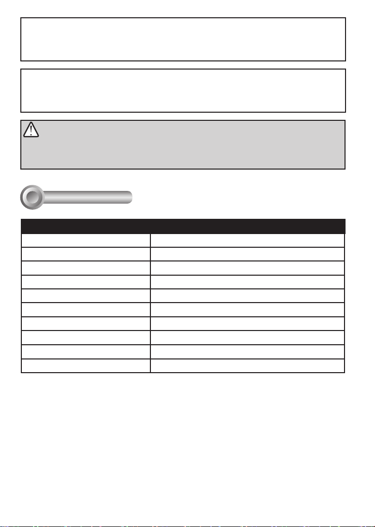
Specications
I
Model Number LPC enclosure
Power Input 24V AC
Max. Output power budget 48W (Street); 80W (Highway)
Power Consumption Window heater: 10W; Blower: 2W; Camera: 6 ~ 8W
Environmental Operation Temp. -20°C ~ +50°C (-4°F ~ +149°F)
Protection Level IP68, IK10
Mounting Bracket Fully-cable Management
Construction Die-cast Aluminum Alloy
Coating White epoxy powder coating
Dimensions 502.8 (L) x 170 (W) x 400 (H) mm
Net Weight 6,482g (9.24 lb)
2
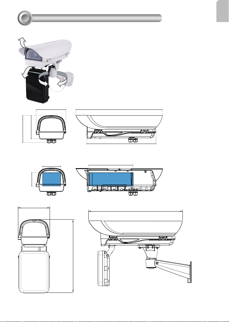
Mounting Conguration & Dimensions
II
Swivel Positions and Directions
English
135.5 mm
158.5 mm
77.4 mm
170
170 mm
105 mm
USABLE
AREA
502.8 mm
400 mm
255 mm
USABLE AREA
502.8
400
3
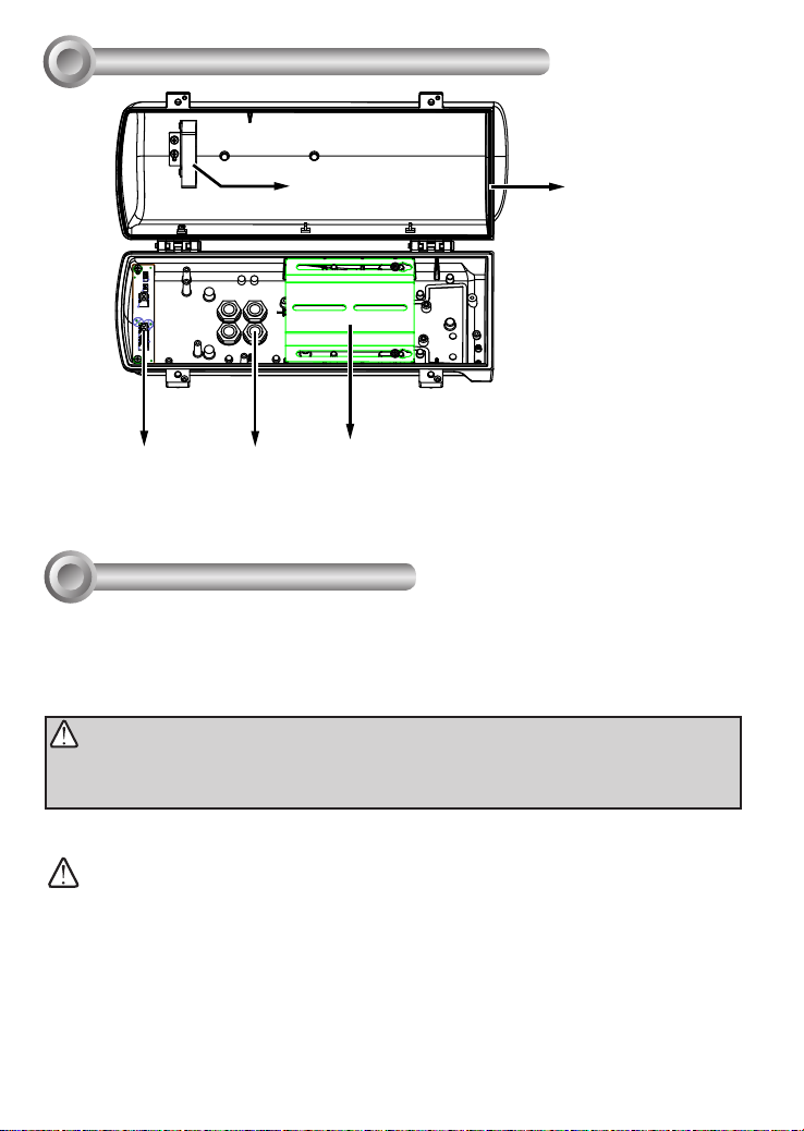
Component Description
III
Window frame heater
coil
Power distribution
board
Installation Suggestions
IV
M16 1/2" Waterproof cable gland
Ventilation fan
Camera Mounting Platform
If you plan to install this camera enclosure into a tropical, sea coastal, or an environment
where salt water or corrosive industrial waste water/moist are present, please seal each
stainless steel screws and ttings with a silicon grease compounds. This will help prevent
electrolysis to occur and extend the life span of the camera and housing.
IMPORTANT:
1. Disconnect devices: A readily accessible disconnect device in the building installation wiring
should be incorporated.
2. Electrical Connection: Only a qualied electrician is allowed to make electrical connections.
WARNING:
• Please avoid eye exposure or apply appropriate protection, such as wearing a pair of Infrared
protection glasses, when working with the product. Always use camera live view to oberve IR
lighting effects.
4
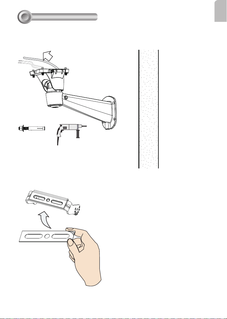
Installation
V
Install the wall-mount bracket to a preferred location at your installation site. Drill
1.
mounting holes and a cable routing hole (if preferred) on a wall. Install the bracket.
Prepare and route the wiring, Ethernet and 24V power source.
Install the IR illuminator to the bottom of the housing. Attach the included grip stricker
2.
to the U bracket.
English
5
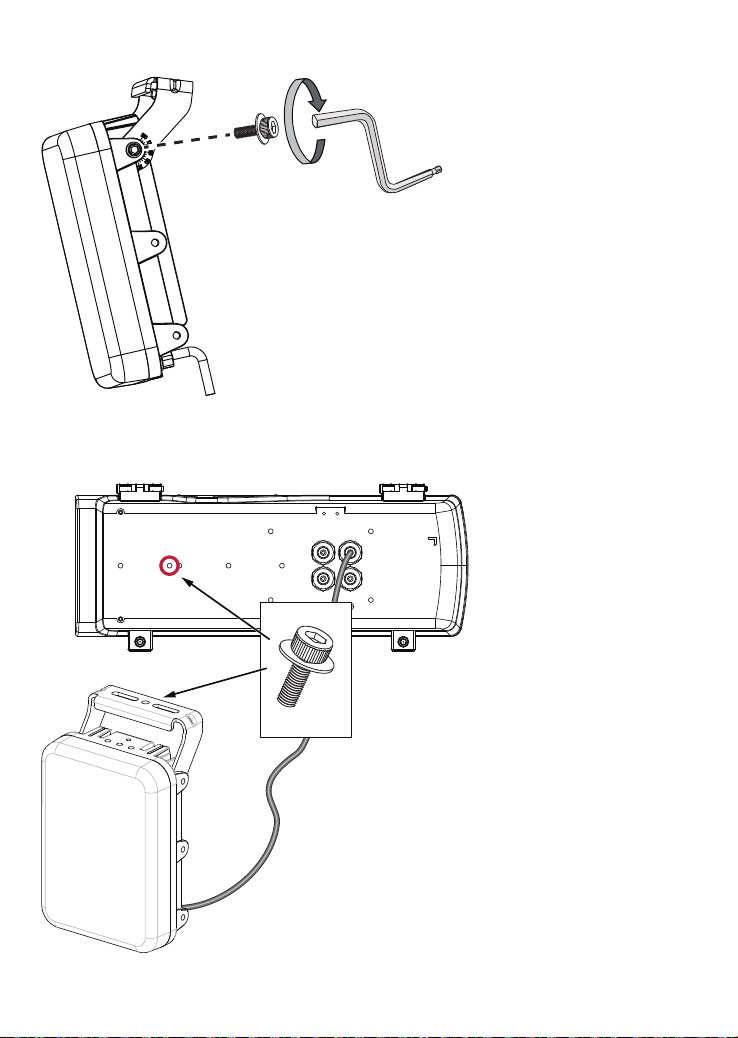
Secure the U bracket to the IR illuminator using the included wrench and hex screws.
3.
Flip the housing over and place it on a clean, stable surface. Secure the IR illuminator
4.
to the bottom of the housing using the included wrench and a hex socket screw.
6

You can turn the IR illuminator so that its at side is parallel with the housing, and that
5.
you can turn the assembly over and work on the inside of the housing.
Prepare power wires, a ground wire, and a CAT5e Ethernet cable. Pass them through
6.
the M16 waterproof connectors under the housing.
Ethernet cable Ø4 ~ 6.5mm
English
Power wires & DI/DO wires,
a combo cable from IR illuminator
7

You may need to remove the RJ45 connector, and use a crimping tool to connect the
Ethernet wires to an RJ45 connector inside the enclosure. Use an Ethernet cable of the
width of 4 ~ 6.5mm.
o: white/orange stripe
O: orange solid
g: white/green stripe
B: blue solid
b: white/blue stripe
G: green solid
br: white/brown stripe
BR: brown solid
When done, tighten up and install the waterproof connectors.
7.
Assemble the camera components, e.g., the CS ring and lens module. Secure the
8.
o
O
g
B
b
G
br
BR
1
2
3
4
5
6
7
8
mounting plate to the bottom of the camera (the label side) using the included screw.
There is a plastic mount pad in the package. You do not need the mounting pad
using the VIVOTEK camera.
8

Adjust the camera's position so that the lens module can ush align with the tempered
9.
glass. Secure the camera using the screws and washers to the bottom of the housing.
Lens flush
w/ edge of
enclosure
Connect 24V power source to the power input terminal. Connect power wires from
10.
the DC 12V output to the camera. Connect the 24V power output to drive the external IRs.
English
Ground
Not used for this model
DC 12V OUT - to camera
AC 24V OUT - to external IR
AC 24V IN - external power
source
9

You should prepare a power adaptor of the sufcient capacity for supplying 24V input.
Below are the requirements:
Total consumption Power adaptor
LPC Highway 80W 7A
LPC Street 48W 5A
Connect the Ethernet cable to the camera's RJ45 socket.
11.
Also pass the combo cable of the IR illuminator through a waterproof connector.
12.
Connect the day/night signal lines from the IR unit to the DI/DO connectors on the
13.
camera's terminal block.
AC/DC pwr
DO+
DO-
DI1+
DI2+
AC/DC pwr
DI3+
DI-
RS485-
RS485+
The day/night mode DI connection enables the synchronization of IR light and the
automated day/night switching mechanism on the camera.
Cable Pinouts (IR Illuminator)
Name Color Gauge Description
V+ Red (20AWG) Power input
V- Black (20AWG)
DI+ Green (26AWG) LED ON/OFF control
DI- Yellow (26AWG) Ground
DO+ Purple (26AWG) Light sensor status output
DO- Blue (26AWG) Ground
RS485+ Orange (26AWG) RS485 interface control
RS485- Brown (26AWG)
12~24V DC±10%
24V AC±10% (50~60Hz), (14.5VDC current controlled)
* Dry contact
Logic level 1(Open) = LED off
Logic level 0(Close to GND) = LED on
* Wet contact
Logic level 1: 4V~40 V = LED off
Logic level 0: 0.8V MAX = LED on
1. Open = Day
2. Short = Night (20 lux for IR ON)
10

A sample connection diagram consisting of CaMate's IR illuminators and the IP816A
camera is shown below. Please refer to your camera's documentation if your camera
comes with different pinouts.
AC/DC pwr
AC/DC pwr
DO+
DO-
DI1+
DI2+
DI3+
DI-
RS485-
RS485+
English
DC 12V
AWG20
AWG26
DI+:
DI-:
DO+:
DO-:
RS485+:
RS485-:
Green
Yellow
Purple
Blue
Orange
Brown
AC24V
AC24V
input
You can connect the ground wires together and connect them to the DI- ground pin
14.
on the terminal. Use a small at blade screwdriver to press the lever on the terminal block.
DI-
DO-
11

Secure the intersection bracket to the bottom of the housing by driving two screws.
15.
Install the housing to the wall-mount bracket by aiming and pressing the spring
16.
mortise, and hook the bracket onto the groove in the spring mortise.
12

When mounting the housing, please carefully place the cable within the cutout on the
bracket. There is a cutout for routing the cable.
Secure the housing to the bracket by fasteninng 4 T30 screws.
17.
English
T30 x 4
13

Adjust zoom and focus and open a web console with the camera to tune for the best
18.
image. When zoom and focus is done, Close the top cover and fasten the hex screws
from below.
Firmware congurable options:
19.
Make sure that the external IR is turned on in the night mode, and that the IR cut lter
option is synchronized with the digital input you connected (default is DI3).
When the "Turn on external IR illuminator in night mode" is selected, a digital output signal
will be triggered to turn on the IR illuminators.
Use the Media > Focus function to tune for a best image focus on your target area.
14

In the Conguration > Media > Image settings page, select an application scenario, LPC
Highway, street, or parking lot mode. The related parameters, such as shutter time, will be
automatically changed for the scenario.
LPC-highway
LPC-street
LPC-parking lot
If preferred, e.g., shooting fast moving vehicles, select the 60fps frame rate.
English
15

In the night mode, check if the input signals are correctly detected. You may simulate
the night mode by blocking the IR unit's light sensor. Change the triggering parameters if
necessary.
If your target area is a stretched out eld of view, such as shooting a part of a highway,
nding the best focus can be a problem. You can use the Snapshot Focus utility to make
sure you acquire clear images of the license plates of passing vehicles.
16

Operation Procedure:
1. Press the Snapshot Recording button, e.g.,
when a car is passing the eld of view. A short,
2.5 seconds of video recording will be available
(including 1 second of pre-recording and
another second of post-recording).
2. The recording takes place on Stream 1 with a
focusing result calculated from the full of the
current eld of view.
3. The Snapshot Focus comes with an embedded
Quick time player. Users can review the
current focusing results on a viewing window.
Users can also use
their keyboard to go through the recording in
a frame-by-frame manner (after the video is
played once).
In this way, an installer can immediately
examine whether the focus is optimal when
a fast going car is captured by video. If not,
he can tune the focus again and review the
imaging result until satised.
4. Users can also download the short recording
clip to a PC. Note that if the Snapshot Focus
page is refreshed or the web session is closed,
the recording will be erased.
Note that you can use the arrow buttons on the
sides of the Focus tuning bar to find the best
focus.
the left arrow key
on
English
17

The parameters of IR illuminator can be controlled via the RS485 connection. You can
FF01
enable the connection in
for the IR illuminator: Pelco D, baud rate - 38400, Data bits - 8, Stop bit - 1, Parity - none.
You can create custom buttons on a web console, such as IR brightness (Lux), threshold,
dimming, etc.
The IR control commands come in an 8 byte format. A sample command is shown below:
Conguration
>
PTZ
Mechanical
>
Customizable IR control
window. Select the defaults
Defaults for IR:
Pelco D
38400
8
1
none
FF012101bf0005E7
FF01
Sync Addr Cmd1 Data1 Data2 Data3 Data4 Chks
1111 1111 0000 0001
The format uses Hexadecimal 0-9, A-F. Each 8-bit byte contains two 4-bit hexadecimal
characters. Two hexadecimal characters contained in each 8-bit eld of message.
2101
001000010000 0001 10111111 0000 0000 00000101 1110 0111
bf00
18
05E7
bitbit
031

Below is the table of congurable data bit (Data1 ~ Data4) values:
bit 31 ~ 24 Device ID: 01 (default) ~ 127
bit 23 ~ 21 Baud rate (0)1200, (1)2400, (2)4800, (3)9600, (4)19200, (5)38400 (default), (6)57600,
(7)115200 bps
bit 20 ~ 16 Brightness: (0) ~ (31), brightness from 0 ~ 100% (default), increment unit is 2.5%
bit 15 ~ 13 LED control mode: (0) DI, (1) Direct, (2) Timer, (3) Light sensor, (4) DI pulse, (5) LPR, (6)
LED dimming by light sensor (default).
bit 12 LED status: (0) Off ready only (default), (1) On
bit 11 ~ 10 Fade in/out: (0) Off, (1) Fast, (2) Slow.
bit 9 DI activation polarity: (0) Low (default), (1) High,
bit 8 DO activation polarity: (0) Low (default), (1) High.
bit 7 ~ 6 Reserved
bit 5 ~ 4 DO mode: (0) Light sensor state (default), (1) LED state, (2) Diagnostic
bit 3 ~ 1 Light sensor day/night threshold: (0) 1 Lux, (1) 5 Lux, (2) 10 Lux, (3) 20 Lux, (4) 50
Lux, (5) 100 Lux, (6) Innite.
bit 0 LED indicator control: (0) Off, (1) On (default)
You can create custom command buttons by entering the Button name and the command
itself:
English
Below are some of the command samples:
Threshold 10% Brightness 100% FF012101bf0005E7
Threshold 20% Brightness 100% FF012101bf0007E9
Threshold 50% Brightness 100% FF012101bf0009EB
Brightness 90% FF012101bc0005E4
Brightness 80% FF012101b80005E0
Brightness 70% FF012101b40005DC
Brightness 60% FF012101b00005D8
Brightness 90% FF012101bc0007E6
Brightness 80% FF012101b80007E2
Brightness 70% FF012101b40007DE
Brightness 60% FF012101b00007DA
Brightness 90% FF012101bc0009E8
Brightness 80% FF012101b80009E4
19

Brightness 70% FF012101b40009E0
Brightness 60% FF012101b00009DC
The customized buttons will appear on the main page for easy access to IR control.
20
 Loading...