

Vivotek IP8133W, IP8133 User manual

H.264 Privacy Button Compact Design
Wired PoE
IP8132
Wired
IP8132/8133/8133W
IP8133W
Wireless
IP8133
Wired PoE
Rev. 1.2
IP Surveillance

VIVOTEK
Table of Contents
Overview.......................................................................................................................................................3
Read Before Use �������������������������������������������������������������������������������������������������������������������������������������3
Package Contents ����������������������������������������������������������������������������������������������������������������������������������� 3
Physical Description �������������������������������������������������������������������������������������������������������������������������������� 4
Install Ferrite Core �����������������������������������������������������������������������������������������������������������������������������������6
Network Deployment ������������������������������������������������������������������������������������������������������������������������������� 8
Software Installation ������������������������������������������������������������������������������������������������������������������������������ 10
Ready to Use ����������������������������������������������������������������������������������������������������������������������������������������� 11
Accessing the Network Camera .................................................................................................................12
Using Web Browsers �����������������������������������������������������������������������������������������������������������������������������12
Using RTSP Players ������������������������������������������������������������������������������������������������������������������������������15
Using 3GPP-compatible Mobile Devices �����������������������������������������������������������������������������������������������16
Using VIVOTEK Recording Software ���������������������������������������������������������������������������������������������������� 17
Main Page ..................................................................................................................................................18
Client Settings ............................................................................................................................................22
Conguration ..............................................................................................................................................24
System ��������������������������������������������������������������������������������������������������������������������������������������������������25
Security �������������������������������������������������������������������������������������������������������������������������������������������������28
HTTPS (Hypertext Transfer Protocol over SSL) �����������������������������������������������������������������������������������29
SNMP (Simple Network Management Protocol) ����������������������������������������������������������������������������������34
Network �������������������������������������������������������������������������������������������������������������������������������������������������35
Wireless (IP8133W) ������������������������������������������������������������������������������������������������������������������������������49
Express Link ������������������������������������������������������������������������������������������������������������������������������������������58
DDNS ����������������������������������������������������������������������������������������������������������������������������������������������������59
Access List �������������������������������������������������������������������������������������������������������������������������������������������61
Audio and Video ������������������������������������������������������������������������������������������������������������������������������������ 64
Motion Detection �����������������������������������������������������������������������������������������������������������������������������������74
Camera Tampering Detection ���������������������������������������������������������������������������������������������������������������77
Homepage Layout �������������������������������������������������������������������������������������������������������������������������������� 78
Application ��������������������������������������������������������������������������������������������������������������������������������������������81
Recording ��������������������������������������������������������������������������������������������������������������������������������������������� 97
System Log ����������������������������������������������������������������������������������������������������������������������������������������101
View Parameters �������������������������������������������������������������������������������������������������������������������������������� 102
Maintenance ����������������������������������������������������������������������������������������������������������������������������������������103
Appendix ..................................................................................................................................................107
URL Commands for the Network Camera ������������������������������������������������������������������������������������������� 107
Technical Specications ����������������������������������������������������������������������������������������������������������������������159
Technology License Notice ������������������������������������������������������������������������������������������������������������������160
Electromagnetic Compatibility (EMC) �������������������������������������������������������������������������������������������������� 161
2 - User's Manual

VIVOTEK
Overview
Read Before Use
The use of surveillance devices may be prohibited by law in your country� The Network Camera is not
only a high-performance web-ready camera but can also be part of a exible surveillance system. It is
the user’s responsibility to ensure that the operation of such devices is legal before installing this unit for
its intended use�
It is important to rst verify that all contents received are complete according to the Package Contents
listed below� Take note of the warnings in the Quick Installation Guide before the Network Camera is
installed; then carefully read and follow the instructions in the Installation chapter to avoid damage due to
faulty assembly and installation� This also ensures the product is used properly as intended�
The Network Camera is a network device and its use should be straightforward for those who have basic
networking knowledge� It is designed for various applications including video sharing, general security/
surveillance, etc� The Configuration chapter suggests ways to best utilize the Network Camera and
ensure proper operations� For creative and professional developers, the URL Commands of the Network
Camera section serves as a helpful reference to customizing existing homepages or integrating with the
current web server�
Package Contents
■ IP8132, IP8133, or IP8133W
■ Power Adapter and Ferrite Core (IP8133/33W)
■ Camera Stand
■ Software CD
■ Warranty Card
■ Quick Installation Guide
■ Screws
■ Antenna (IP8133W)
Revision History
■ Rev. 1.0: Initial release
■ Rev. 1.1: UPdated RTSP audio port screen captures, and updated available network bit rates.
■ Rev. 1.2: Corrected specications and removed mentioning of micro SD card slot.
User's Manual - 3

VIVOTEK
Physical Description
Front Panel
IP8132
Status LED
Microphone
Lens
IP8133W
Status LED
Microphone
NOTE:
The front view of IP8133 is identical
to that of IP8133W except the
wireless antenna�
White-light LED
Item LED status Description
LED Denitions
1 Steady Red Power on and system boot
Red LED off Power off
2 Blink Green every 1 sec� Network connected
Steady Red Network failed
3 Blink Green every 2 sec� Audio muted
4 Blink Orange every 2 sec� Privacy button pressed
5 Blink Green, RED, and Orange
Upgrading rmware
intermittently
6 Blink Orange every 0�15 sec� Restoring default
Speaker
PIR Sensor
4 - User's Manual

Back Panel
VIVOTEK
IP8132
General I/O Terminal
Block
Recessed Reset Button
General I/O
Terminal Block
IP8132
MAC:0002D132C353
This device complies with part 15 of the FCC rules. Operation is subject to the following two conditions:
(1)This device may not cause harmful interference, and
(2) this device must accept any interference received, including interference that may cause undesired operation.
Pat. 6,930,709
IP8133 & 8133W
Ethernet 10/100 RJ45 Socket
Power Cord Socket
Privacy Button
Ethernet 10/100
RJ45 Socket
Reset Button
Antenna
Connector
(IP8133W)
IP8133W
MAC:0002D132C353
This device complies with part 15 of the FCC rules. Operation is subject to the following two conditions:
(1)This device may not cause harmful interference, and
(2) this device must accept any interference received, including interference that may cause undesired operation.
Pat. 6,930,709
WPS Button
(IP8133W)
NOTE:
Two antennas come with the IP8133W� They are
installed by users by turning clockwise to attach to
connectors�
Power Cord
2
Socket
Antenna
Connector
(IP8133W)
Privacy Button
User's Manual - 5

VIVOTEK
General I/O Terminal Block
This Network Camera provides a general I/O terminal block which is used to connect external
input / output devices. The pin denitions are described below.
Pin Name
4 Power
3 Digital Output +
2 Digital Input 1 Ground
Hardware Reset
The reset button is used to reset the system or restore the factory default settings� Sometimes
resetting the system can return the camera to normal operation� If the system problems remain
after reset, restore the factory settings and install again�
Reset: Press and release the recessed reset button with a paper clip or thin object. Wait for the
Network Camera to reboot�
Restore: Press and hold the recessed reset button until the status LED rapidly blinks orange.
Note that all settings will be restored to factory default� Upon successful restore, the status LED
will blink green once per second during normal operation�
Install Ferrite Core
1� Unsnap the two halves of the ferrite core�
2� Attach the ferrite core to the power cord as close to the DC connector as possible� Fold the
ferrite core over the power cord, wrap the power cord once, and snap the small latches
together�
Ferrite Core
6 - User's Manual

Wireless Connection: Using the WPS Button
1� Make sure your AP (Access Point) and Operating System support WPS (Wi-Fi
Protected Setup) functions� WPS enables easy setup with compatible APs�
2� Disconnect your LAN cable, and wait for the LED to turn red�
3� Press the WPS button for 1 second� You can then hear vocal instructions (in English)
from the camera speaker�
4� Press and hold down the WPS button on your AP
(some router/AP will have a virtual button on their
management software instead)� Refer to your AP's
documentation for details using its WPS functions�
Wireless AP
VIVOTEK
2
WPS
WPS Button
WPS Button
When WPS conguration is done, wireless connectivity will be established and the
security encryption, such as WEP or WPA-PSK, will be synchronized with the AP�
Use the IW2 utility to nd the camera. As for IP setting, the camera's use of DHCP
or static IP is determined by your conguration on the network camera via the webbased conguration of rmware. The camera's default is DHCP.
NOTE:
1. WPS may not work if your AP is congured with a "hidden" SSID.
2� If no WPS-enabled AP is detected, the camera will repeat vocal instructions by
every 20 seconds, and if the camera still can not detect an AP after 2 minutes,
the wireless setup will be cancelled�
3. If a camera is assigned with a xed IP outside the AP's network segment, wireless
setup will fail�
4� A wired connection always has a higher priority, and hence wireless setup will not
take effect when the RJ45 LAN port is connected�
User's Manual - 7

VIVOTEK
Network Deployment
Setting up the Network Camera over the Internet
This section explains how to congure the Network Camera to an Internet connection�
1� If you have external devices such as sensors and alarms, make connections from general I/O
terminal block�
2� Connect the camera to a switch via Ethernet cable� Use a Category 5 Cross Cable when
Network Camera is directly connected to PC�
3� Connect the power cable from the Network Camera to a power outlet�
4: Power
3: Digital output
1
2: Digital input
2
1: Ground
POWER
COLLISION
1
Ethernet Switch
LINK
RECEIVE
2
PARTITION
3
4
5
IP8132
MAC:0002D132C353
This device complies with part 15 of the FCC rules. Operation is subject to the following two conditions:
(1)This device may not cause harmful interference, and
(2) this device must accept any interference received, including interference that may cause undesired operation.
Pat. 6,930,709
3
NOTE:
The IP8133 can acquire power through a cable connection with a PoE switch� However,
when so connected, the camera is only to be connected to PoE networks without routing
to outside plants�
There are several ways to set up the Network Camera over the Internet� The rst way is to set
up the Network Camera behind a router� The second way is to utilize a static IP� The third way is
to use PPPoE�
Internet connection via a router
Before setting up the Network Camera over the Internet, make sure you have a router and follow
the steps below�
1� Connect your Network Camera behind a router, the Internet environment is illustrated below�
Regarding how to obtain your IP address, please refer to Software Installation on page 10 for
details�
8 - User's Manual

VIVOTEK
L
A
N (
Local Area Network)
R
o
u
t
e
r
I
P
a
d
dre
s
s
W
A
N (Wide Area Network )
R
o
u
t
e
r
I
P
a
d
dre
s
s
f
r
o
m
I
S
P
IP address : 192.168.0.3
Subnet mask : 255.255.255.0
Default router : 192.168.0.1
IP address : 192.168.0.2
Subnet mask : 255.255.255.0
Default router : 192.168.0.1
Internet
Cable or DSL Modem
WAN (Wide Area Network )
Router IP address : from ISP
LINK
POWER
COLLISION
RECEIVE
1
2
PARTITION
3
4
5
LAN (Local Area Network)
Router IP address : 192.168.0.1
2� In this case, if the Local Area Network (LAN) IP address of your Network Camera is
192�168�0�3, please forward the following ports for the Network Camera on the router�
■ HTTP port
■ RTSP port
■ RTP port for video
■ RTCP port for video
■ RTP port for audio
■ RTCP port for audio
If you have changed the port numbers on the Network page, please open the ports accordingly
on your router� For information on how to forward ports on the router, please refer to your
router’s user’s manual�
3� Find out the public IP address of your router provided by your ISP (Internet Service Provider)�
Use the public IP and the secondary HTTP port to access the Network Camera from the
Internet� Please refer to Network Type on page 35 for details�
Internet connection with static IP
Choose this connection type if you are required to use a static IP for the Network Camera�
Please refer to LAN on page 35 for details�
Internet connection via PPPoE (Point-to-Point over Ethernet)
Choose this connection type if you are connected to the Internet via a DSL Line� Please refer to
PPPoE on page 36 for details�
User's Manual - 9

VIVOTEK
Software Installation
Installation Wizard 2 (IW2), free-bundled software included on the product CD, helps you set up
your Network Camera on the LAN�
1� Install IW2 under the Software Utility directory from the software CD�
Double click the IW2 shortcut on your desktop to launch the program�
2� The program will conduct an analysis of your network environment�
After your network environment is analyzed, please click Next to continue the program�
3� The program will search for all VIVOTEK network devices on the same LAN�
4� After searching, the main installer window will pop up� Click on the MAC and model name
which matches the product label on your device to connect to the Network Camera via
Internet Explorer�
IP8132
MAC:0002D132C353
This device complies with part 15 of the FCC rules. Operation is subject to the following two conditions:
(1)This device may not cause harmful interference, and
(2) this device must accept any interference received, including interference that may cause undesired operation.
Pat. 6,930,709
00-02-D1-32-C3-53 192.168.5.119 IP8132
0002D132C353
10 - User's Manual

VIVOTEK
Ready to Use
1� A browser session with the Network Camera should prompt as shown below�
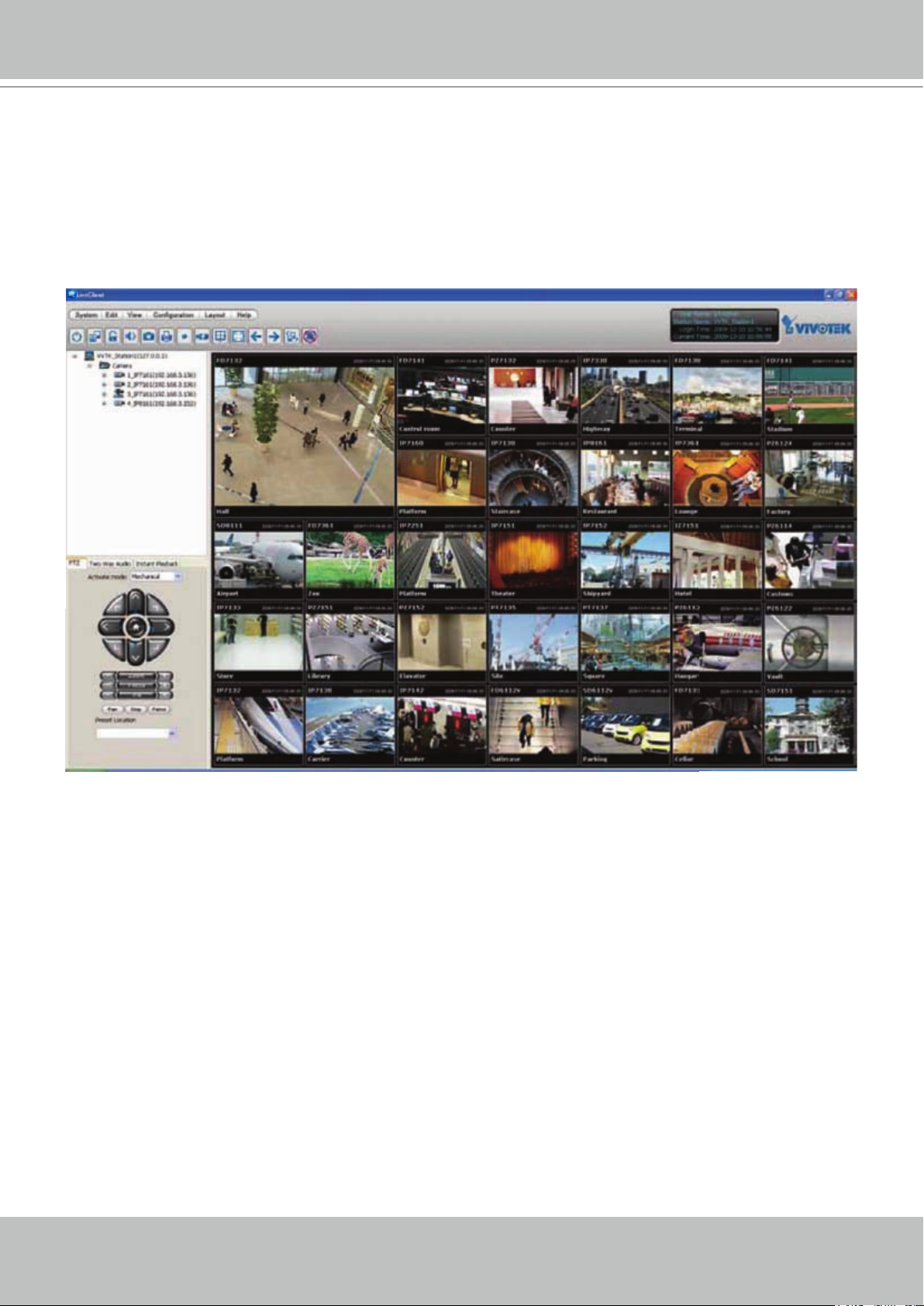
2� You should be able to see live video from your camera� You may also install the 32-channel
recording software from the software CD in a deployment consisting of multiple cameras� For
its installation details, please refer to its related documents�
User's Manual - 11

VIVOTEK
Accessing the Network Camera
This chapter explains how to access the Network Camera through web browsers, RTSP players,
3GPP-compatible mobile devices, and VIVOTEK recording software�
Using Web Browsers
Use Installation Wizard 2 (IW2) to access to the Network Cameras on the LAN�
If your network environment is not a LAN, follow these steps to access the Network Camera:
1� Launch your web browser (ex� Microsoft
2. Enter the IP address of the Network Camera in the address eld. Press Enter�
3� The live video will be displayed in your web browser�
4. If it is the rst time installing the VIVOTEK network camera, an information bar will pop up as
shown below� Follow the instructions to install the required plug-in on your computer�
®
Internet Explorer, Mozilla Firefox, or Netscape)�
NOTE:
► For Mozilla Firefox or Netscape users, your browser will use Quick Time to stream the live
video. If you do not have Quick Time on your computer, please download it rst, then launch
the web browser�
12 - User's Manual

VIVOTEK
► By default, the Network Camera is not password-protected. To prevent unauthorized access,
it is highly recommended to set a password for the Network Camera�
For more information about how to enable password protection, please refer to Security on
page 28�
► If you see a dialog box indicating that your security settings prohibit running ActiveX
®
Controls, please enable the ActiveX
Controls for your browser�
®
1� Choose Tools > Internet Options > Security > Custom Level�
2. Look for Download signed ActiveX
®
controls; select Enable or Prompt� Click OK�
3. Refresh your web browser, then install the Active X
complete installation�
®
control� Follow the instructions to
User's Manual - 13

VIVOTEK
IMPORTANT!
•
•
•
Currently the Network Camera utilizes 32-bit ActiveX plugin. You CAN NOT open a
management/view session with the camera using a 64-bit IE browser�
If you encounter this problem, try execute the Iexplore.exe program from C:\
Windows\SysWOW64. A 32-bit version of IE browser will be installed.
On Windows 7, the 32-bit explorer browser can be accessed from here: C:\Program
Files (x86)\Internet Explorer\iexplore.exe.
14 - User's Manual

VIVOTEK
Using RTSP Players
To view the MPEG-4 streaming media using RTSP players, you can use one of the following
players that support RTSP streaming�
Quick Time Player
Real Player
VLC media player
1� Launch the RTSP player�
mpegable Player
2� Choose File > Open URL� A URL dialog box will pop up�
3. The address format is rtsp://<ip address>:<rtsp port>/<RTSP streaming access name for
pvPlayer
stream1 or stream2>
As most ISPs and players only allow RTSP streaming through port number 554, please set the
RTSP port to 554� For more information, please refer to RTSP Streaming on page 47�
For example:
rtsp://192.168.5.151:554/live3.sdp
4� The live video will be displayed in your player�
For more information on how to configure the RTSP access name, please refer to RTSP
Streaming on page 47 for details�
Video 16:38:01 2011/01/17
User's Manual - 15

VIVOTEK
Using 3GPP-compatible Mobile Devices
To view the streaming media through 3GPP-compatible mobile devices, make sure the Network
Camera can be accessed over the Internet� For more information on how to set up the Network
Camera over the Internet, please refer to Setup the Network Camera over the Internet on page 8�
To utilize this feature, please check the following settings on your Network Camera:
1� Because most players on 3GPP mobile phones do not support RTSP authentication, make
sure the authentication mode of RTSP streaming is set to disable�
For more information, please refer to RTSP Streaming on page 47�
2� As the bandwidth on 3G networks is limited, you will not be able to use a large video size�
Please set the video streaming parameters as listed below�
For more information, please refer to Viewing Window on page 69�
Video Mode MPEG-4
Frame size 176 x 144
Maximum frame rate 5 fps
Intra frame period 1S
Video quality (Constant bit rate) 40kbps
3� As most ISPs and players only allow RTSP streaming through port number 554, please set
the RTSP port to 554� For more information, please refer to RTSP Streaming on page 47�
4� Launch the player on the 3GPP-compatible mobile devices (ex� Real Player)�
5� Type the following URL commands into the player�
The address format is rtsp://<public ip address of your camera>:<rtsp port>/<RTSP streaming
access name for stream 3>�
For example:
rtsp://192.168.5.151:554/live3.sdp
16 - User's Manual
VIVOTEK
Using VIVOTEK Recording Software
The product software CD also contains recording software, allowing simultaneous monitoring
and video recording for multiple Network Cameras� Please install the recording software; then
launch the program to add the Network Camera to the Channel list� For detailed information
about how to use the recording software, please refer to the user’s manual of the software or
download it from http://www.vivotek.com�
User's Manual - 17

VIVOTEK
Resize Buttons
Main Page
This chapter explains the layout of the main page. It is composed of the following sections:
VIVOTEK INC� Logo, Host Name, Camera Control Area, Configuration Area, Menu, and Live
Video Window�
VIVOTEK INC. Logo
Camera Control Area
Hide Button
Configuration Area
Host Name
Live View Window
VIVOTEK INC. Logo
Click this logo to visit the VIVOTEK website�
Host Name
The host name can be customized to t your needs. For more information, please refer to System on page 25.
Camera Control Area
Video Stream: This Network Camera supports multiple streams (streams 1 to 3) simultaneously. You can
select any one for live viewing� For more information about multiple streams, please refer to page 69 for
detailed information�
Digital Output: Click to turn the digital output device on or off.
White-light Illuminator: Click to turn on the white LED (available on IP8133 and IP8133W). The LED also
turns on when triggered by the occurrence of an event� Please refer to page 85 for more information�
Light adjustment setting is found on page 27.
Manual Trigger: Click to enable/disable an event trigger manually. Please congure an event setting
on Application page before enable this function. A total of 3 event settings can be congured. For more
information about event settings, please refer to page 82�
If you want to hide this item on the homepage, please go to the Homepage Layout page to uncheck “show
manual trigger button”� Please refer to page 78 for detailed illustration�
Conguration Area
Client Settings: Click this button to access the client setting page. For more information, please refer to
Client Settings on page 22�
Conguration: Click this button to access the conguration page of the Network Camera. It is suggested
that a password be applied to the Network Camera so that only the administrator can configure the
Network Camera� For more information, please refer to Conguration on page 24�
Language: Click this button to choose a language for the user interface. Language options are available
18 - User's Manual

VIVOTEK
in: English, Deutsch, Español, Français, Italiano,
日本語
, Português,
簡体中文
, and
繁體中文
Hide Button
You can click the hide button to hide the control panel or display the control panel�
Resize Buttons
:
Click the Auto button, the video cell will resize automatically to t the monitor.
Click 100% is to display the original homepage size�
Click 50% is to resize the homepage to 50% of its original size�
Click 25% is to resize the homepage to 25% of its original size�
Live Video Window
■ The following window is displayed when the video mode is set to H.264 / MPEG-4:
Video Title
Title and Time
MPEG-4 Protocol and Media Options
Time
Video 13:44:17 2011/01/17
�
Video and Audio Control Buttons
Video Title: The video title can be congured. For more information, please refer to Video Settings on
page 64�
H�264 / MPEG-4 Protocol and Media Options: The transmission protocol and media options for H.264 /
MPEG-4 video streaming. For further conguration, please refer to Client Settings on page 22.
Time: Display the current time. For further conguration, please refer to Video Settings on page 64.
Title and Time: The video title and time can be stamped on the streaming video. For further conguration,
please refer to Video Settings on page 64�
Video and Audio Control Buttons: Depending on the Network Camera model and Network Camera
conguration, some buttons may not be available.
Snapshot: Click this button to capture and save still images. The captured images will be displayed
in a pop-up window� Right-click the image and choose Save Picture As to save it in JPEG (*.jpg) or BMP
(*�bmp) format�
Digital Zoom: Click and uncheck “Disable digital zoom” to enable the zoom operation. The navigation
screen indicates the part of the image being magnied. To control the zoom level, drag the slider bar. To
move to a different area you want to magnify, drag the navigation screen�
User's Manual - 19

VIVOTEK
Pause: Pause the transmission of the streaming media. The button becomes the Resume button
after clicking the Pause button�
Stop: Stop the transmission of the streaming media. Click the Resume button to continue
transmission�
Start MP4 Recording: Click this button to record video clips in MP4 file format to your computer.
Press the
Stop MP4 Recording button to end recording� When you exit the web browser, video
recording stops accordingly. To specify the storage destination and le name, please refer to MP4 Saving
Options on page 23 for details�
Volume: When the Mute function is not activated, move the slider bar to adjust the volume on the
local computer�
Mute: Turn off the volume on the local computer� The button becomes the Audio On button after
clicking the Mute button�
Talk: Click this button to talk to people around the Network Camera. Audio will project from the
embedded/external speaker connected to the Network Camera� Click this button
again to end
conversation�
Mic Volume: When the Mute function is not activated, move the slider bar to adjust the
microphone volume�
Mute: Turn off the Mic volume on the local computer� The button becomes the Mic On button
after clicking the Mute button�
Full Screen: Click this button to switch to full screen mode. Press the “Esc” key to switch back to normal
mode�
■ The following window is displayed when the video mode is set to MJPEG:
Video Title
Title and Time
2011/01/17 13:44:17
Video 13:44:17 2011/01/17
Time
Video Control Buttons
Video Title: The video title is user-congurable. For more information, please refer to Video Settings on
page 64�
Time: Display the current time. For more information, please refer to
Video Settings on page 64�
Title and Time: Video title and time can be stamped on the streaming video. For more information, please
refer to Video Settings on page 64�
Video Control Buttons: Depending on the Network Camera model and Network Camera conguration,
20 - User's Manual

VIVOTEK
some buttons may not be available�
Snapshot: Click this button to capture and save still images. The captured images will be displayed
in a pop-up window� Right-click the image and choose Save Picture As to save it in JPEG (*.jpg) or BMP
(*�bmp) format�
Digital Zoom: Click and uncheck “Disable digital zoom” to enable the zoom operation. The navigation
screen indicates the part of the image being magnied. To control the zoom level, drag the slide bar. To
move to a different area you want to magnify, drag the navigation screen�
Start MP4 Recording: Click this button to record video clips in MP4 file format to your computer.
Press the
Stop MP4 Recording button to end recording� When you exit the web browser, video
recording stops accordingly. To specify the storage destination and le name, please refer to MP4 Saving
Options on page 23 for details�
Full Screen: Click this button to switch to full screen mode. Press the “Esc” key to switch back to
normal mode�
User's Manual - 21

VIVOTEK
Client Settings
This chapter explains how to select the stream transmission mode and saving options on the
local computer� When completed with the settings on this page, click Save on the page bottom
to enable the settings�
H.264 / MPEG-4 Media Options
Select to stream video or audio data or both� This is enabled only when the video mode is set to H�264 or
MPEG-4�
H.264 / MPEG-4 Protocol Options
H.264/MPEG-4 Protocol Options
Depending on your network environment, there are four transmission modes of H�264 or MPEG-4
streaming:
UDP unicast: This protocol allows for more real-time video streams. However, network packets may be
lost due to network burst trafc and images may be broken. Activate UDP connection when occasions
require time-sensitive responses and the video quality is less important� Note that each unicast client
connecting to the server takes up additional bandwidth and the Network Camera allows up to ten
simultaneous accesses�
UDP multicast: This protocol allows multicast-enabled routers to forward network packets to all clients
requesting streaming media� This helps to reduce the network transmission load of the Network Camera
while serving multiple clients at the same time� Note that to utilize this feature, the Network Camera must
be configured to enable multicast streaming at the same time� For more information, please refer to
RTSP Streaming on page 47�
TCP: This protocol guarantees the complete delivery of streaming data and thus provides better video
quality� The downside of this protocol is that its real-time effect is not as good as that of the UDP protocol�
HTTP: This protocol allows the same quality as TCP protocol without needing to open specic ports for
streaming under some network environments� Users inside a firewall can utilize this protocol to allow
streaming data through�
22 - User's Manual

VIVOTEK
MP4 Saving Options
Users can record live video as they are watching it by clicking Start MP4 Recording on the main
page. Here, you can specify the storage destination and le name.
Folder: Specify a storage destination for the recorded video les.
File name prex: Enter the text that will be appended to the front of the video le name.
Add date and time sufx to the le name: Select this option to append the date and time to the end of the
le name.
CLIP_20110117-180853
File name prefix
Date and time suffix
The format is: YYYYMMDD_HHMMSS
Local Streaming Buffer Time
Due to the unsteady bandwidth ow, the live streaming may lag and not be very smoothly. If you enable
this option, the live streaming will be stored on the camera’s buffer area for a few seconds before playing
on the live viewing window� This will help you see the streaming more smoothly�
If you enter 3000 Millisecond, the streaming will delay 3 seconds�
User's Manual - 23

VIVOTEK
Conguration
Click Configuration on the main page to enter the camera setting pages� Note that only
Administrators can access the conguration page.
VIVOTEK offers an easy-to-use user interface that helps you set up your network camera with
minimal effort. To simplify the setting procedure, two types of user interfaces are available:
Advanced Mode for professional users and Basic Mode for entry-level users� Some advanced
functions (HTTPS/ SNMP/ Access list/ Homepage layout/ Application/ Recording/ System log/
View parameters) are not displayed in Basic Mode�
If you want to set up advanced functions, please click [Advanced Mode] on the bottom of the
conguration list to quickly switch to Advanced Mode.
In order to simplify the user interface, the detailed information will be hidden unless you click on
the function item. When you click on the rst sub-item, the detailed information for the rst sub-
item will be displayed; when you click on the second sub-item, the detailed information for the
second sub-item will be displayed and that of the rst sub-item will be hidden.
The following is the interface of the Basic Mode and the Advanced Mode:
Basic Mode
Configuration List
24 - User's Manual
Click to switch to Advanced Mode
Firmware Version

Advanced Mode
VIVOTEK
Configuration List
Click to switch to Basic Mode
Firmware Version
Each function on the conguration list will be explained in the following sections. Those functions that are
displayed only in Advanced Mode are marked with
Advanced Mode
� If you want to set up advanced
functions, please click [Advanced Mode] on the bottom of the conguration list to quickly switch over.
System
This section explains how to congure the basic settings for the Network Camera, such as the
host name and system time. It is composed of the following three columns: System, System
Time, and DI and DO. When nished with the settings on this page, click Save at the bottom of
the page to enable the settings�
System
Host name: Enter a desired name for the Network Camera. The text will be displayed at the top of the
main page�
Turn off the LED indicators: If you do not want to let others know that the network camera is in operation,
you can select this option to turn off the LED indicators�
User's Manual - 25
VIVOTEK
Disable Privacy Button: The privacy button is on the rear panel of the camera. You are able to manually
stop the operation of video monitoring for privacy concern by pushing the button� Later on, you can push
the button again to resend the video� If you want to disable the function of privacy button, please select
this item�
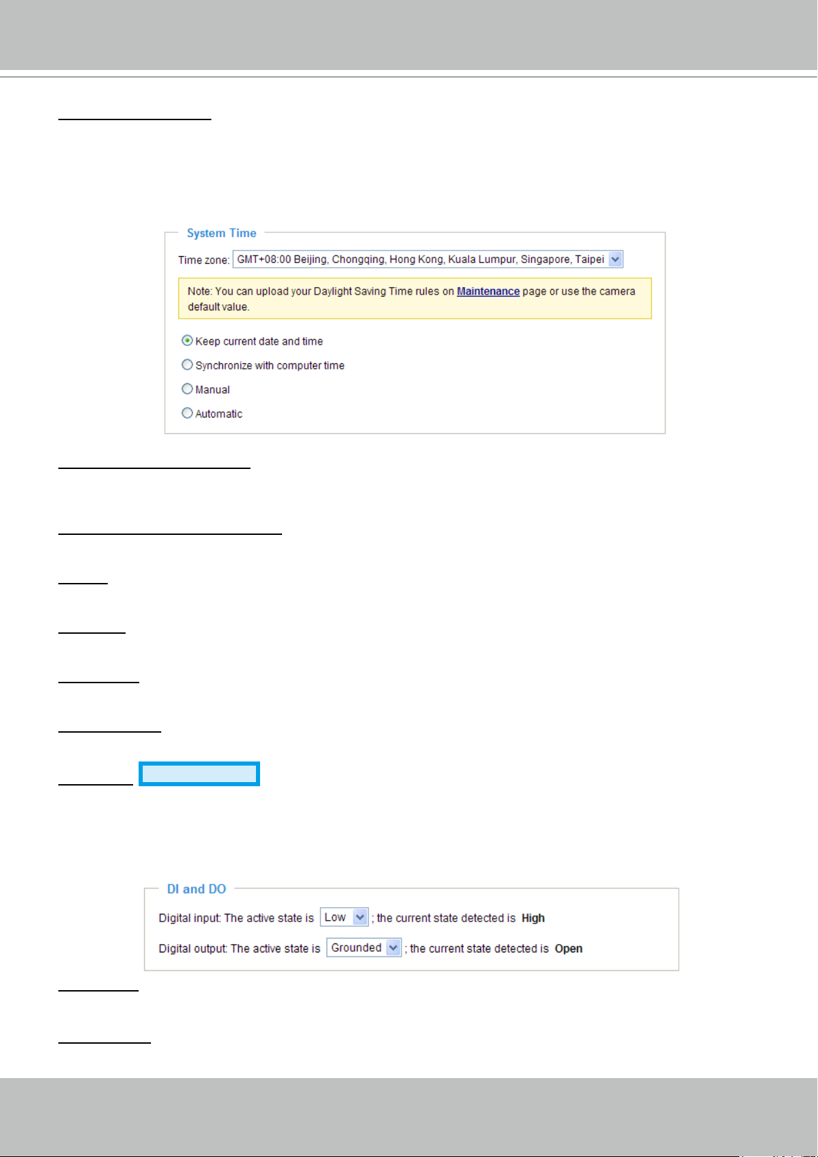
System Time
Keep current date and time: Select this option to preserve the current date and time of the Network
Camera� The Network Camera’s internal real-time clock maintains the date and time even when the
power of the system is turned off�
Synchronize with computer time: Select this option to synchronize the date and time of the Network
Camera with the local computer� The read-only date and time of the PC is displayed as updated�
Manual: The administrator can enter the date and time manually. Note that the date and time format are
[yyyy/mm/dd] and [hh:mm:ss].
Automatic: The Network Time Protocol is a protocol which synchronizes computer clocks by periodically
querying an NTP Server�
NTP server: Assign the IP address or domain name of the time-server. Leaving the text box blank
connects the Network Camera to the default time servers�
Update interval: Select to update the time using the NTP server on an hourly, daily, weekly, or monthly
basis�
Time zone
Advanced Mode
: Select the appropriate time zone from the list. If you want to upload
Daylight Savings Time rules on the Maintenance page, please refer to Upload / Export Daylight Saving
Time Conguration File on page 104 for details.
DI and DO
Digital input: Select High or Low to dene normal status for the digital input. The Network Camera will
report the current status�
Digital output: Select Grounded or Open to define normal status for the digital output. The Network
Camera will show whether the trigger is activated or not�
26 - User's Manual

VIVOTEK
White-light Illuminators
ON: The white-light LED allows you to illuminate the monitored area when an event occurs. You can
select to turn on the LED directly to a congurable brightness level or gradually light up to that level. You
can manually enter a percentage number in the text elds. The white-light LED can be manually lit using
a button on the home page or passively triggered by a camera event�
OFF: Select to turn off the LED directly or let the light gradually fade out.
User's Manual - 27
VIVOTEK
Security
This section explains how to enable password protection and create multiple accounts�
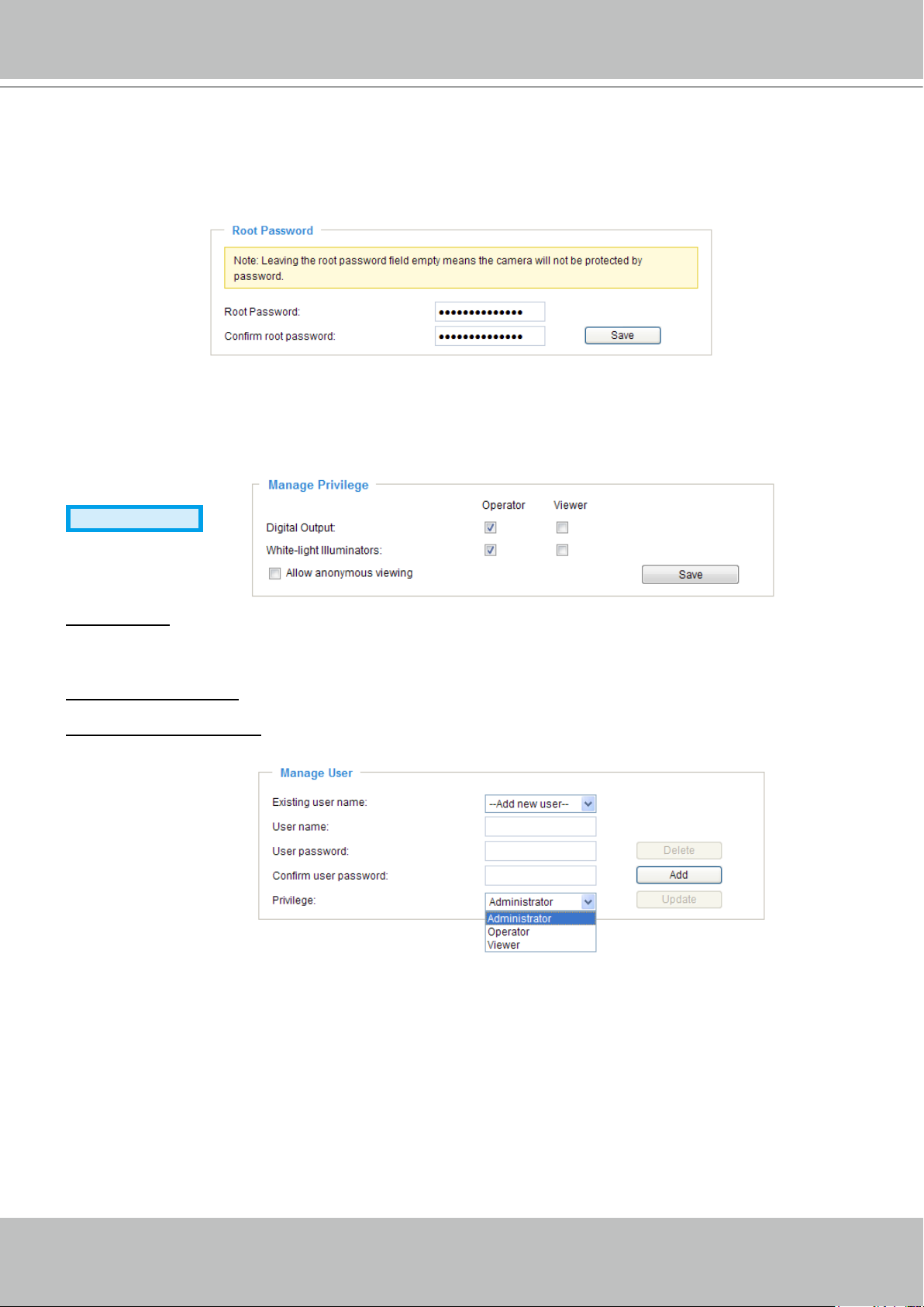
Root Password
The administrator account name is “root”, which is permanent and can not be deleted� If you want to add
more accounts in the Manage User column, please apply the password for the “root” account rst.
1� Type the password identically in both text boxes, then click Save to enable password protection�
2� A window will prompt for authentication; type the correct user’s name and password in their respective
elds to access the Network Camera.
Manage Privilege
Advanced Mode
Digital Output: You can modify the manage privilege of operators or viewers. Check or uncheck the item,
then click Save to enable the settings� If you give Viewers the privilege, Operators will also have the
ability to control the Network Camera through the main page� (Please refer to Main Page on page 24�)
White-light Illuminators: Determines if an operator or viewer can control the white LED.
Allow anonymous viewing: If you check this item, any client can access the live stream without entering a
User ID and Password�
Manage User
Administrators can add up to 20 user accounts�
1� Input the new user’s name and password�
2� Select the privilege level for the new user account� Click Add to enable the setting�
Access rights are sorted by user privilege (Administrator, Operator, and Viewer)� Only administrators can
access the Conguration page. Though operators cannot access the Conguration page, they can use
the URL Commands to get and set the value of parameters� For more information, please refer to URL
Commands of the Network Camera on page 107� Viewers access only the main page for live viewing�
Here you also can change a user’s access rights or delete user accounts�
1� Select an existing account to modify�
2� Make necessary changes and click Update or Delete to enable the setting�
28 - User's Manual

VIVOTEK
HTTPS (Hypertext Transfer Protocol over SSL)
Advanced Mode
This section explains how to enable authentication and encrypted communication over SSL
(Secure Socket Layer)� It helps protect streaming data transmission over the Internet on higher
security level�
Enable HTTPS
Check this item to enable HTTPS communication, then select a connection option: "HTTP & HTTPS"
or "HTTPS only". Note that you have to create and install a certicate rst in the second column before
clicking the Save button�
Create and Install Certicate Method
Before using HTTPS for communication with the Network Camera, a Certicate must be created rst.
There are three ways to create and install a certicate:
Create self-signed certificate automatically
1� Select this option�
2. In the rst column, check Enable HTTPS secure connection, then select a connection option: “HTTP
& HTTPS” or “HTTPS only”.
3� Click Save to generate a certicate.
User's Manual - 29

VIVOTEK
https://
4. The Certicate Information will automatically be displayed in the third column as shown below. You can
click Property to view detailed information about the certicate.
5� Click Home to return to the main page� Change the address from “http://” to “https://“ in the address
bar and press Enter on your keyboard� Some Security Alert dialogs will pop up� Click OK or Yes to
enable HTTPS�
https://192.168.5.151/index.html
30 - User's Manual
 Loading...