

Vivotek IP8130 User Manual
Cube
IP8130W/8131W
Network Camera
User’s Manual
IP8130W/8131W: 1MP • 802.11n WLAN • WPS
Rev. 1.0

VIVOTEK
Table of Contents
Overview ����������������������������������������������������������������������������������������������������������������������������������������4
Revision History �������������������������������������������������������������������������������������������������������������������������������������� 4
Read Before Use ������������������������������������������������������������������������������������������������������������������������������������� 5
Package Contents ����������������������������������������������������������������������������������������������������������������������������������� 5
Symbols and Statements in this Document ��������������������������������������������������������������������������������������������� 5
Physical Description �������������������������������������������������������������������������������������������������������������������������������� 6
Install Camera to Stand ��������������������������������������������������������������������������������������������������������������������������� 8
Network Deployment ����������������������������������������������������������������������������������������������������������������������������� 11
Software Installation ������������������������������������������������������������������������������������������������������������������������������ 14
Ready to Use ����������������������������������������������������������������������������������������������������������������������������������������� 15
Accessing the Network Camera
Using Web Browsers ����������������������������������������������������������������������������������������������������������������������������� 16
Wireless Connection: Using the WPS Button ���������������������������������������������������������������������������������������� 19
Wireless Connection: Manual Conguration ����������������������������������������������������������������������������������������� 20
Using RTSP Players ������������������������������������������������������������������������������������������������������������������������������ 21
Using 3GPP-compatible Mobile Devices ����������������������������������������������������������������������������������������������� 22
Using VIVOTEK Recording Software ���������������������������������������������������������������������������������������������������� 23
Main Page
Go to ������������������������������������������������������������������������������������������������������������������������������������������������������ 28
Client Settings
Conguration
System > General settings �������������������������������������������������������������������������������������������������������������������� 34
System > Homepage layout ����������������������������������������������������������������������������������������������������������������� 36
System > Logs �������������������������������������������������������������������������������������������������������������������������������������� 39
System > Parameters ��������������������������������������������������������������������������������������������������������������������������� 41
System > Maintenance �������������������������������������������������������������������������������������������������������������������������� 42
Media > Image ������������������������������������������������������������������������������������������������������������������������������������ 46
Media > Video ��������������������������������������������������������������������������������������������������������������������������������������� 53
Media > Video ��������������������������������������������������������������������������������������������������������������������������������������� 54
Media > Audio���������������������������������������������������������������������������������������������������������������������������������������� 58
Network > General settings ������������������������������������������������������������������������������������������������������������������� 59
Network > Streaming protocols ����������������������������������������������������������������������������������������������������������� 67
Network > SNMP (Simple Network Management Protocol) ������������������������������������������������������������������ 74
Wireless > WLAN (IP8130W and IP8131W) ����������������������������������������������������������������������������������������� 75
Security > User Account ������������������������������������������������������������������������������������������������������������������������ 77
Security > HTTPS (Hypertext Transfer Protocol over SSL) ��������������������������������������������������������78
Security > Access List ������������������������������������������������������������������������������������������������������������������������� 85
PTZ > PTZ settings ������������������������������������������������������������������������������������������������������������������������������� 88
Event > Event settings��������������������������������������������������������������������������������������������������������������������������� 92
Applications > Motion detection����������������������������������������������������������������������������������������������������������� 105
Applications > Digital Input ������������������������������������������������������������������������������������������������������������������ 108
Applications > Tampering detection ���������������������������������������������������������������������������������������������������� 108
Recording > Recording settings ��������������������������������������������������������������������������������������������������������� 109
Local storage > SD card management ������������������������������������������������������������������������������������������������ 114
�������������������������������������������������������������������������������������������������������������������������������������������������
������������������������������������������������������������������������������������������������������������������������������������������
��������������������������������������������������������������������������������������������������������������������������������������������
������������������������������������������������������������������������������������������������������������
16
24
29
33
2 - User's Manual

Local storage > Content management ����������������������������������������������������������������������������������������������������� 115
Appendix
URL Commands for the Network Camera ������������������������������������������������������������������������������������������������ 118
Technical Specications ���������������������������������������������������������������������������������������������������������������������������193
Technology License Notice �����������������������������������������������������������������������������������������������������������������������194
Electromagnetic Compatibility (EMC) �������������������������������������������������������������������������������������������������������195
�����������������������������������������������������������������������������������������������������������������������������������������������������
VIVOTEK
118
User's Manual - 3

VIVOTEK
Overview
VIVOTEK IP8130/31/30W/31W are compact cube cameras designed for indoor surveillance� The elegant
design makes it an ideal solution for ofces, shops and homes. A built-in microphone further increases
the level of surveillance by recording sound within a 6 meter radius. Moreover, the IP8131/31W are
equipped with IR LEDs and IR-cut lter, providing clear video in completely dark environments.
The IP8130/31/30W/31W support the industry-standard H.264 compression technology, drastically
reducing file sizes and conserving valuable network bandwidth. Moreover, the IP8130W/31W boast
802.11b/g/n compatible wireless connection, making installation easier and more cost-efficient. The
WPS function of IP8130W/31W makes wireless conguration easy and straightforward. Together with
the multi-lingual 32-channel recording software ST7501, users can set up an easy-to-use IP surveillance
system with ease. VIVOTEK also provides the smart phone application iViewer, both on iPhone and
Android phones, enable users to monitor live video off-site.
Revision History
■ Rev. 1.0: Initial release
4 - User's Manual
VIVOTEK
i
Read Before Use
The use of surveillance devices may be prohibited by law in your country� The Network Camera
is not only a high-performance web-ready camera but can also be part of a exible surveillance
system� It is the user’s responsibility to ensure that the operation of such devices is legal before
installing this unit for its intended use�
It is important to first verify that all contents received are complete according to the Package
Contents listed below� Take note of the warnings in the Quick Installation Guide before the Network
Camera is installed; then carefully read and follow the instructions in the Installation chapter to
avoid damage due to faulty assembly and installation� This also ensures the product is used
properly as intended�
The Network Camera is a network device and its use should be straightforward for those who
have basic networking knowledge. It is designed for various applications including video sharing,
general security/surveillance, etc. The Configuration chapter suggests ways to best utilize the
Network Camera and ensure proper operations. For creative and professional developers, the URL
Commands of the Network Camera section serves as a helpful reference to customizing existing
homepages or integrating with the current web server�
Package Contents
■ IP8130W or IP8131W
■ Screws & Plastic Anchors
■ Power Adaptor (+12V, 1A)
■ Camera Stand
■ Antenna
■ Software CD
■ Warranty Card
■ Quick Installation Guide
■ Ethernet cable x1
Symbols and Statements in this Document
INFORMATION: provides important messages or advices that might help prevent
inconvenient or problem situations�
NOTE: Notices provide guidance or advices that are related to the functional integrity of
the machine�
Tips: Tips are useful information that helps enhance or facilitae an installation, function,
or process�
WARNING: or IMPORTANT: These statements indicate situations that can be dangerous
or hazardous to the machine or you�
Electrical Hazard: This statement appears when high voltage electrical hazards might
occur to an operator�
User's Manual - 5
VIVOTEK
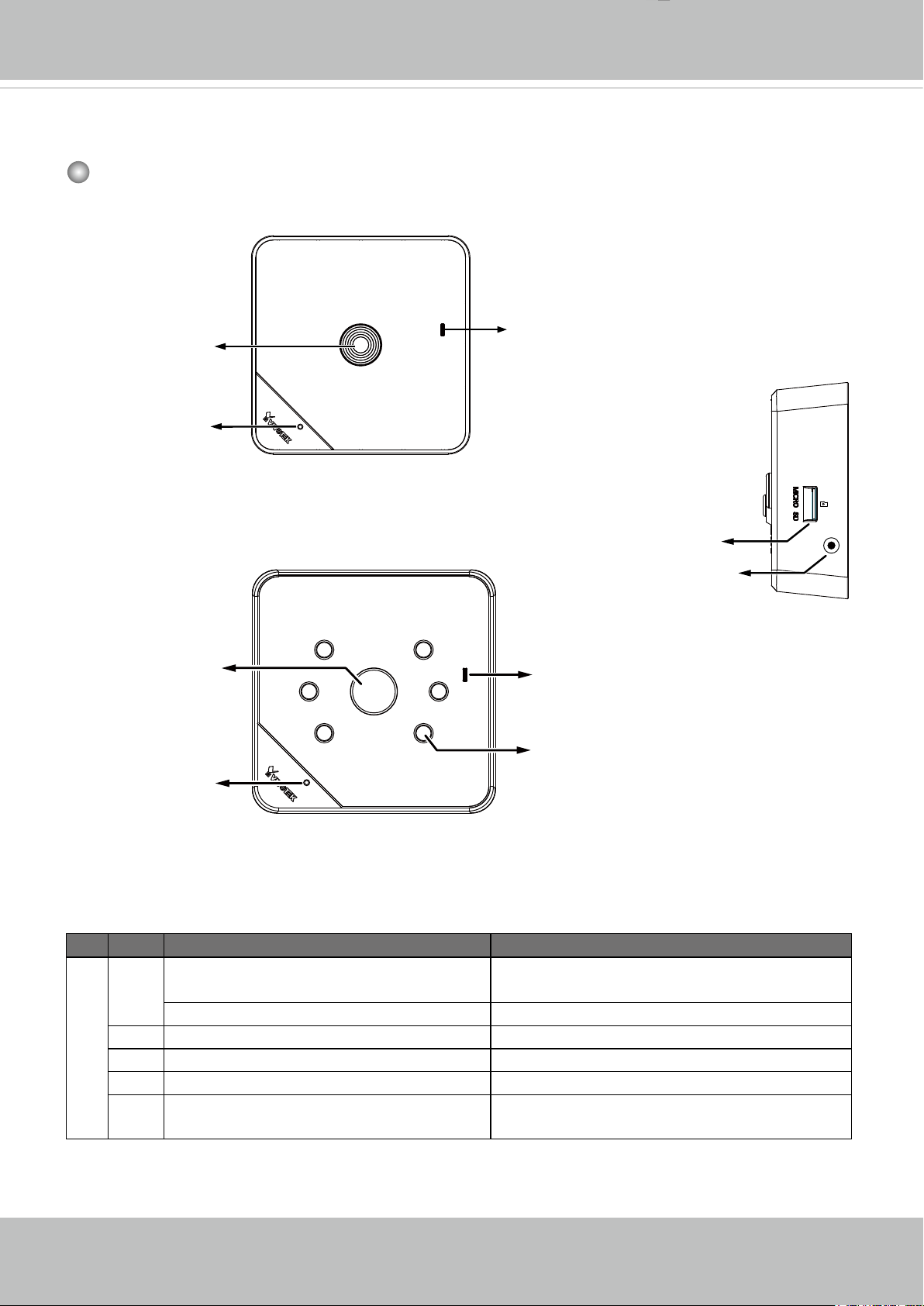
Physical Description
Front Panel
Lens
Microphone
IP8130W
IP8131W
Status LED
MicroSD/SDHC/SDXC
Card Slot
WPS button
(wireless models)
WPS
Lens
Status LED
IR LEDs
Microphone
Item LED status
LED Denitions
Description
1 Steady Red Powered on, during system boot, or
indicating no network connection
All LED off Powered off
2 Blinking Blue every 0�15 sec� Searching for WPS
3 Blinking Green every 1 sec� Network connected (wired or wireless)
4 Blinking Green and RED intermittently
Upgrading rmware
5 Blinking Orange every 0�15 sec� Restoring default
6 - User's Manual
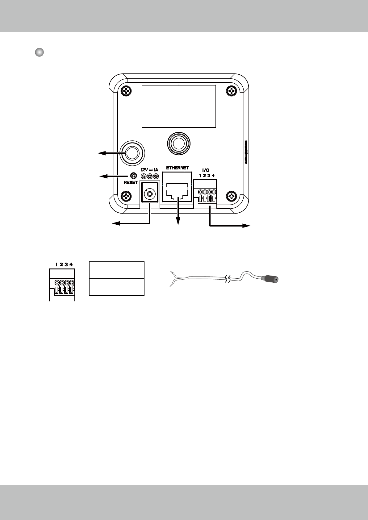
Rear Panel
Antenna
Connector (for
wireless models)
Reset Button
VIVOTEK
The back panels are identical for all models.
Power Cord
Socket
1 DI2 DI+
3 Audio GND
4 Audio Out
Ethernet 10/100
RJ45 Socket
Audio out cable is user-supplied�
General I/O
Terminal Block
User's Manual - 7
VIVOTEK
0002D10766AD
IP8130W
Install Camera to Stand
Attach the camera to stand and orient the shooting angle. If preferred, use the included
screws to secure the the camera stand to a mounting surface�
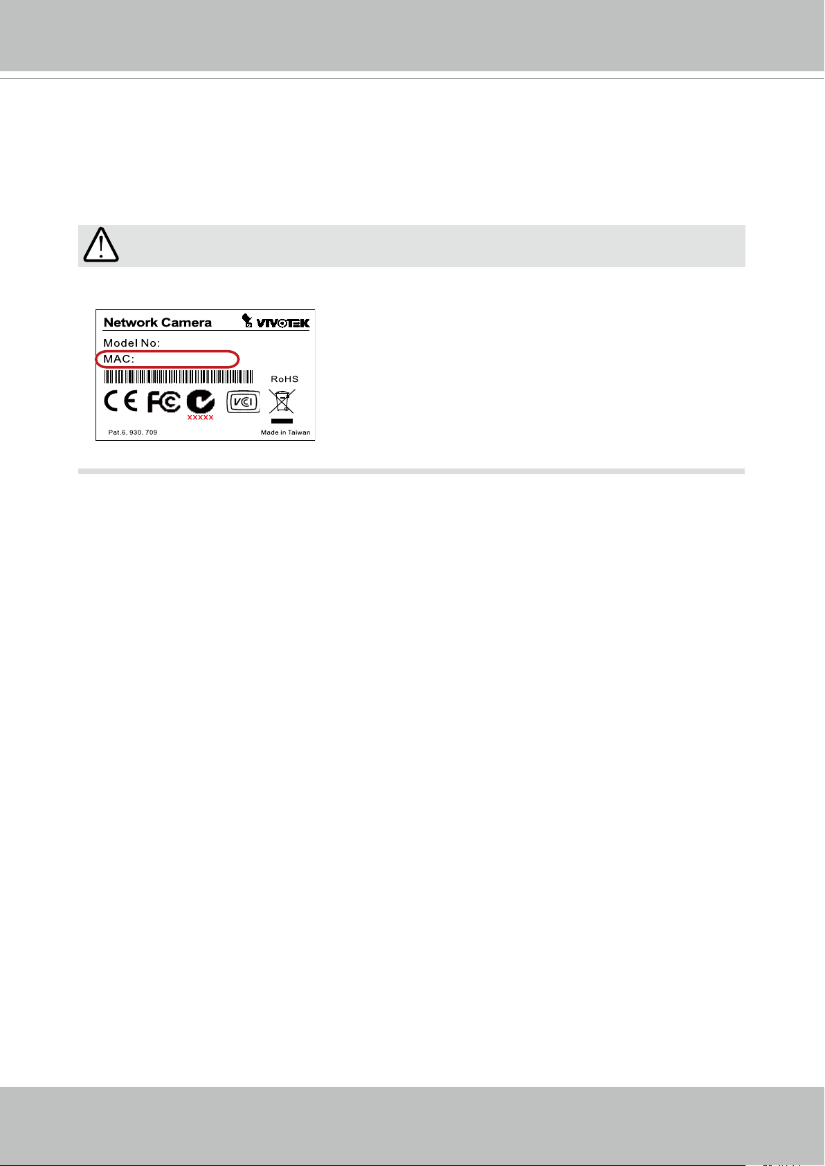
IMPORTANT:
Record the MAC address before installing the camera�
8 - User's Manual
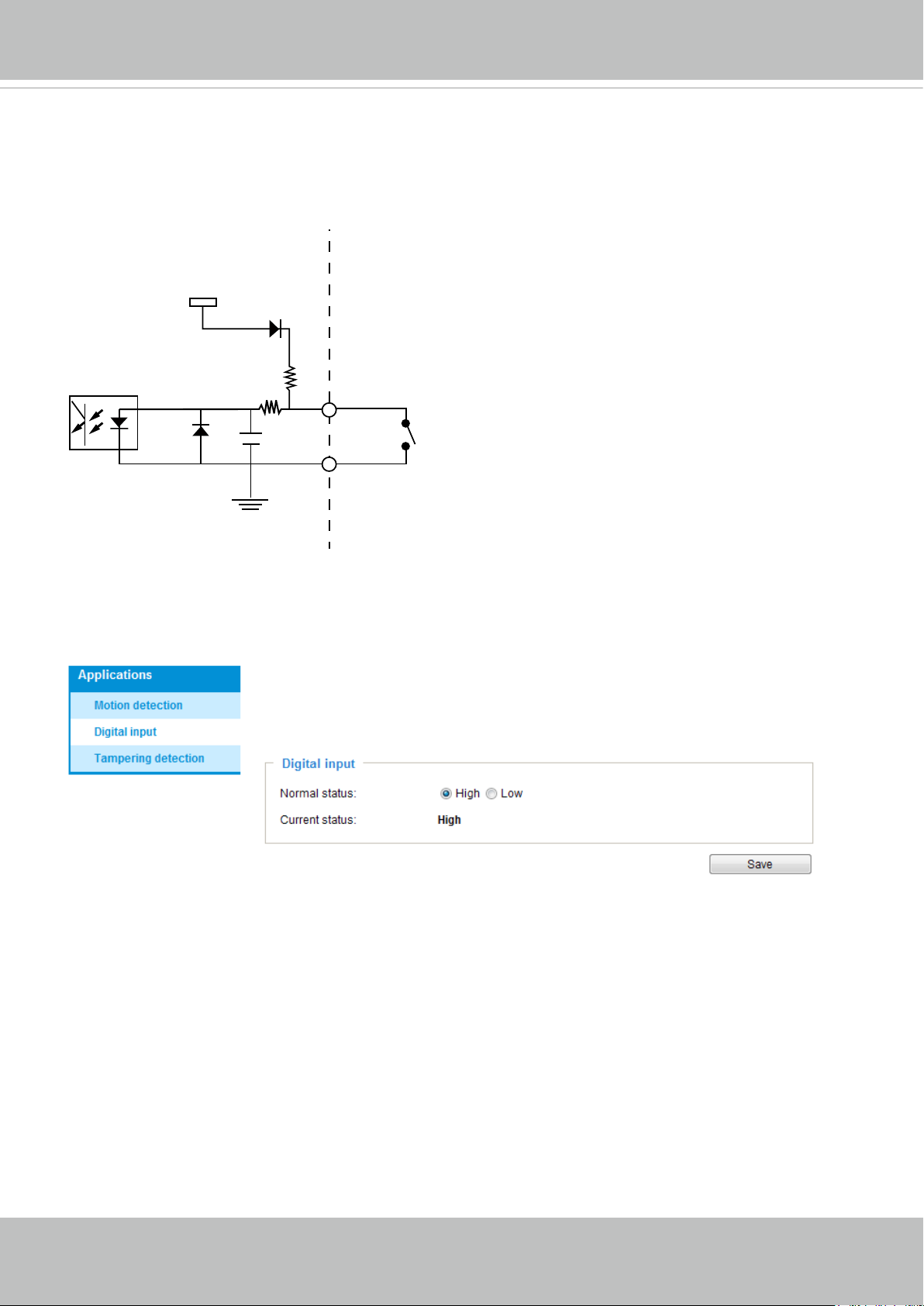
Digital Input Diagram
Please refer to the following illustration for the connection method�
Max. voltage: 40V
3.3V
DI+
Digital input
DI-
DI-: Ground
VIVOTEK
Connect a digital input device to the input pins of the camera� From the Applications > Digital
Input page, you can let camera report the current signal status as High or Low to determine the
signal’s Normal status during operation�
User's Manual - 9
VIVOTEK
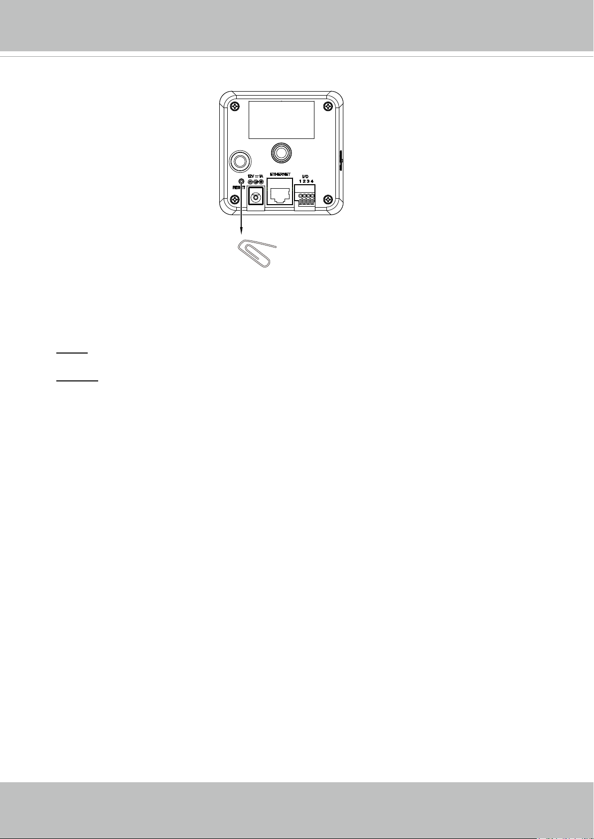
Hardware Reset
Reset Button
The reset button is used to reset the system or restore the factory default settings�
Sometimes resetting the system can return the camera to normal operation� If the system
problems remain after reset, restore the factory settings and install again.
Reset: Press and release the reset button� Wait for the Network Camera to reboot�
Restore: Press and hold the recessed reset button until the status LED rapidly blinks� Note
that all settings will be restored to factory default. Upon successful restore, the status LED
will blink green and red during normal operation�
Micro SD/SDHC/SDXC Card Capacity
This network camera is compliant with Micro SD/SDHC/SDXC of 8, 16, 32GB, or 64GB
capacity SD cards�
10 - User's Manual
VIVOTEK
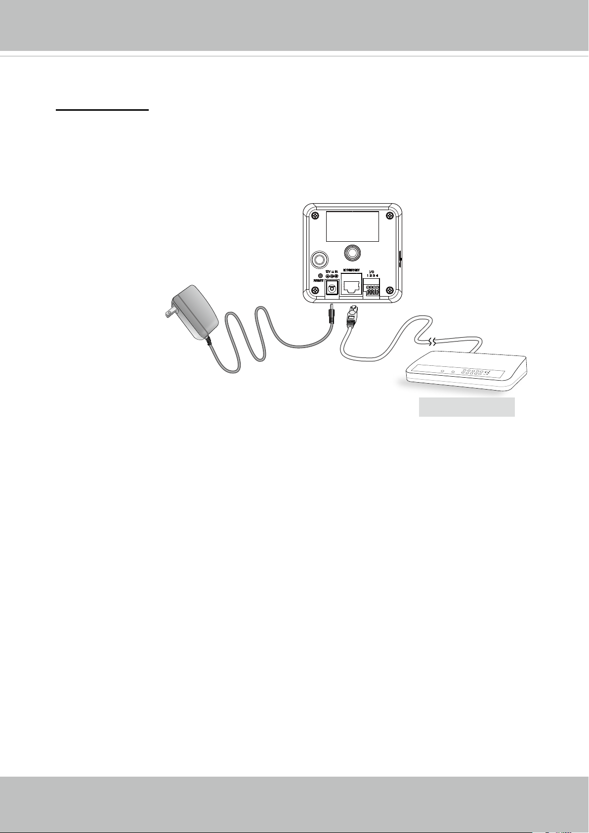
Network Deployment
LAN Connection
1. If you have external devices such as sensors and alarms, make connections from
general I/O terminal block�
2� Connect the camera to a switch via Ethernet cable or directly to a computer� Ethernet
must be connected before power on�
3� Connect the supplied power cable from
the camera to a power outlet�
Wireless conguration will be discussed later on page 19.
POWER
COLLISION
1
LINK
RECEIVE
2
PARTITION
3
4
5
Non-PoE Switch
User's Manual - 11
VIVOTEK
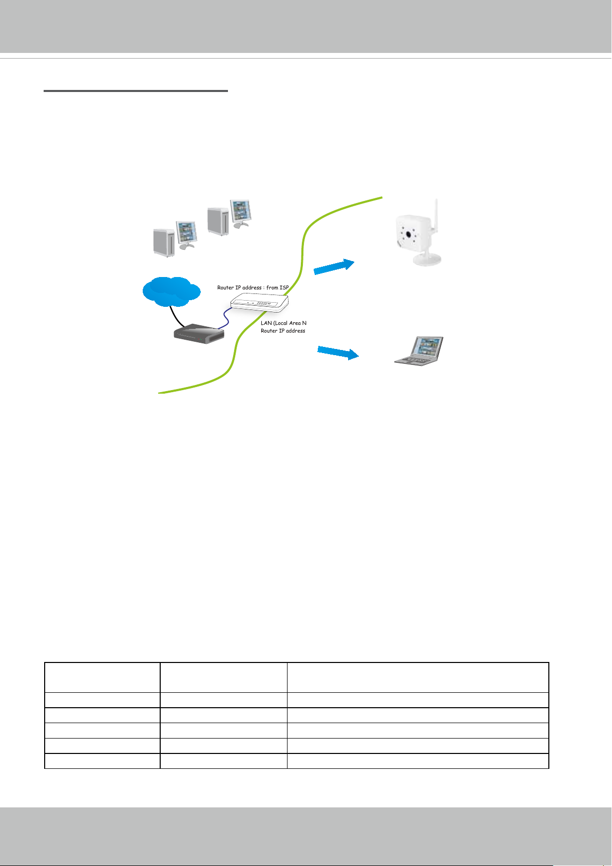
Internet connection via a router
Before setting up the Network Camera over the Internet, make sure you have a router and follow
the steps below�
1. Connect your Network Camera behind a router, the Internet environment is illustrated below.
Regarding how to obtain your IP address, please refer to Software Installation on page 14 for
details�
IP address : 192.168.0.3
Subnet mask : 255.255.255.0
Default router : 192.168.0.1
IP address : 192.168.0.2
Subnet mask : 255.255.255.0
Default router : 192.168.0.1
Internet
Cable or DSL Modem
WAN (Wide Area Network )
Router IP address : from ISP
LINK
POWER
COLLISION
RECEIVE
1
2
PARTITION
3
4
5
LAN (Local Area Network)
Router IP address : 192.168.0.1
2. In this case, if the Local Area Network (LAN) IP address of your Network Camera is
192.168.0.3, please forward the following ports for the Network Camera on the router.
■ HTTP port: default is 80; secondary HTTP port is 8080
■ RTSP port: default is 554
■ RTP port for audio: default is 5558
■ RTCP port for audio: default is 5559
■ RTP port for video: default is 5556
■ RTCP port for video: default is 5557
If you have changed the port numbers on the Network page, please open the ports
accordingly on your router. For information on how to forward ports on the router, please refer
to your router’s user’s manual�
3� Find out the public IP address of your router provided by your ISP (Internet Service Provider)�
Use the public IP and the secondary HTTP port to access the Network Camera from the
Internet� Please refer to Network Type on page 59 for details�
For example, your router and IP settings may look like this:
Device IP Address: internal
port
IP Address: External Port (Mapped port on the
router)
Public IP of router 122�146�57�120
LAN IP of router 192�168�2�1
Camera 1 192�168�2�10:80 122�146�57�120:8000
Camera 2 192�168�2�11:80 122�146�57�120:8001
��� ��� ���
12 - User's Manual
VIVOTEK
Congure the router, virtual server or rewall, so that the router can forward any data coming into a precongured port number to a network camera on the private network, and
allow data from the camera to be transmitted to the outside of the network over the same
path�
From Forward to
122�146�57�120:8000 192�168�2�10:80
122�146�57�120:8001 192�168�2�11:80
��� ���
When properly congured, you can access a camera behind the router using the HTTP
request as follows: http://122�146�57�120:8000
If you change the port numbers on the Network conguration page, please open the ports
accordingly on your router. For example, you can open a management session with your
router to congure access through the router to the camera within your local network.
Please consult your network administrator for router conguration if you have troubles with
the conguration.
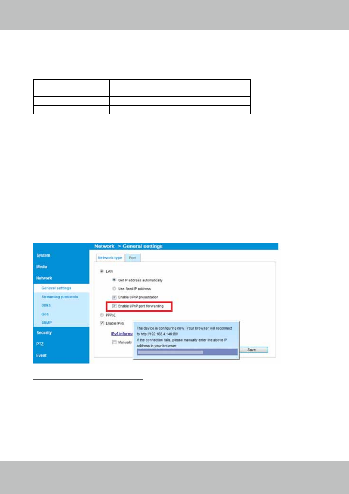
For more information with network conguration options (such as that of streaming ports),
please refer to Conguration > Network Settings� VIVOTEK also provides the automatic
port forwarding feature as an NAT traversal function with the precondition that your router
must support the UPnP port forwarding feature�
Internet connection with static IP
Choose this connection type if you are required to use a static IP for the Network Camera�
Please refer to LAN setting on page 59 for details�
User's Manual - 13
VIVOTEK
Software Installation
Installation Wizard 2 (IW2), free-bundled software included on the product CD, helps you set up
your Network Camera on the LAN�
IW
1� Install IW2 under the Software Utility directory from the software CD�
Double-click the IW2 shortcut on your desktop to launch the program�
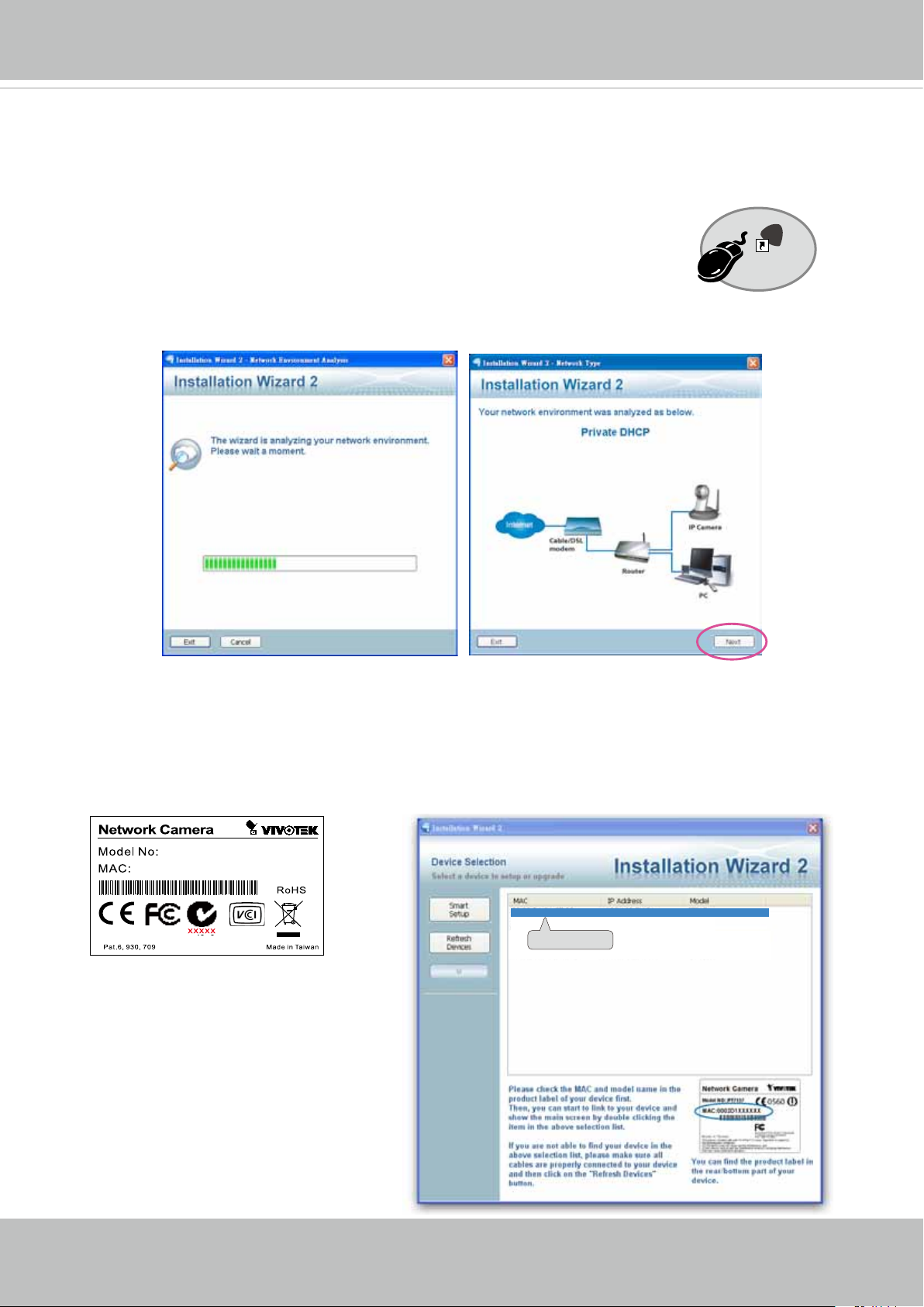
2� The program will conduct an analysis of your network environment�
After your network environment is analyzed, please click Next to continue the program�
2
Installation
Wizard 2
3� The program will search for all VIVOTEK network devices on the same LAN�
4. After a brief search, the installer window will prompt. Click on the MAC and model name
that matches the one printed on the product label� You can then double-click on the address to
open a management session with the Network Camera�
IP8131W
0002D10766AD
00-02-D1-73-02-02 192.168.5.151 IP8131W
0002D1730202
14 - User's Manual
VIVOTEK
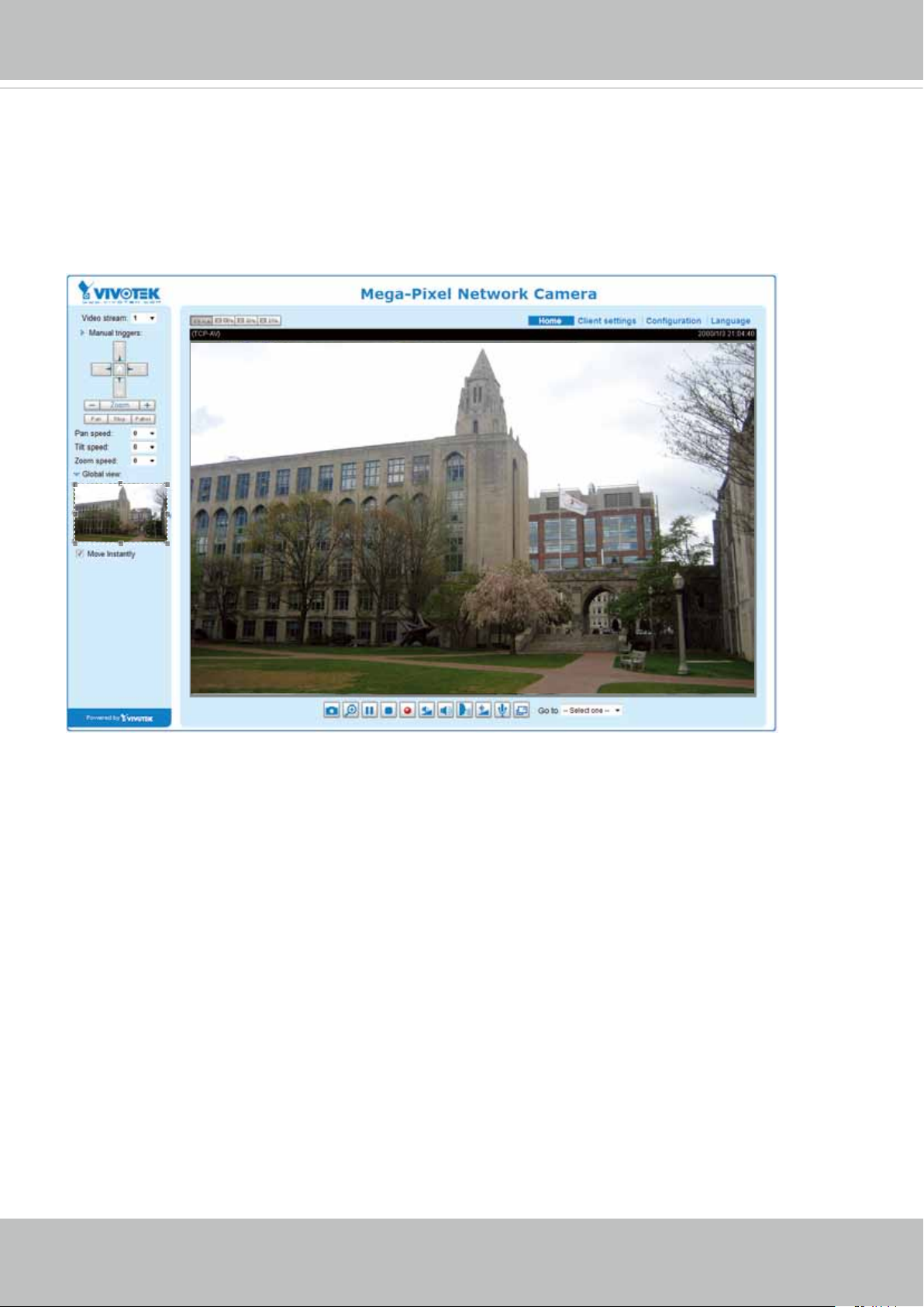
Ready to Use
1� A browser session with the Network Camera should prompt as shown below�
2� You should be able to see live video from your camera� You may also install the 32-channel
recording software from the software CD in a deployment consisting of multiple cameras� For
its installation details, please refer to its related documents.
User's Manual - 15
VIVOTEK
Accessing the Network Camera
This chapter explains how to access the Network Camera through web browsers, RTSP players,
3GPP-compatible mobile devices, and VIVOTEK recording software.
Using Web Browsers
Use Installation Wizard 2 (IW2) to access the Network Cameras on LAN�
If your network environment is not a LAN, follow these steps to access the Netwotk Camera:
1. Launch your web browser (e.g., Microsoft
2. Enter the IP address of the Network Camera in the address eld. Press Enter�
3� The live video will be displayed in your web browser�
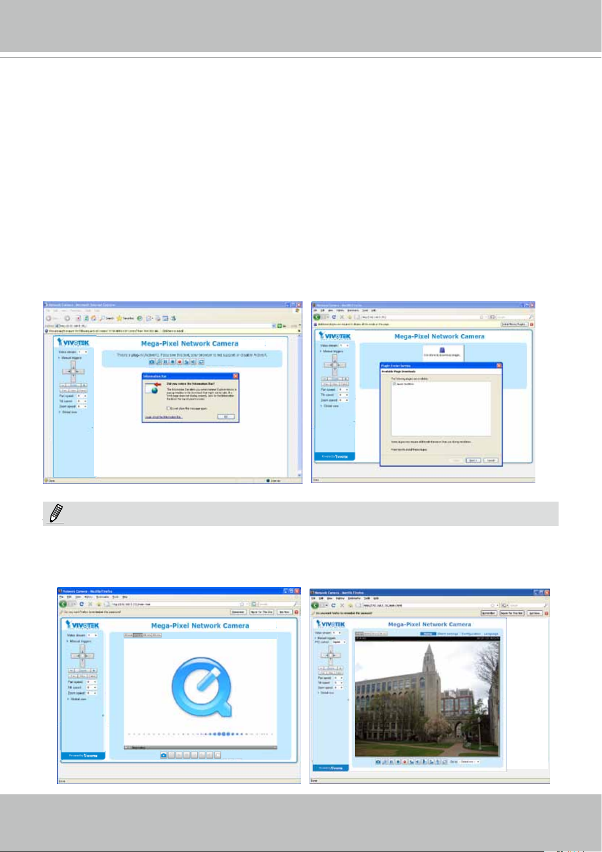
4. If it is the rst time installing the VIVOTEK network camera, an information bar will pop up as
shown below� Follow the instructions to install the required plug-in on your computer�
®
Internet Explorer or Mozilla Firefox)�
NOTE
NOTE:
► For Mozilla Firefox users, your browser will use Apple’s Quick Time to stream the live video.
If you don’t have Quick Time on your computer, please download it rst, then launch the web
browser�
16 - User's Manual
VIVOTEK
► By default, the Network Camera is not password-protected. To prevent unauthorized access,
it is highly recommended to set a password for the Network Camera�
For more information about how to enable password protection, please refer to Security on
page 77�
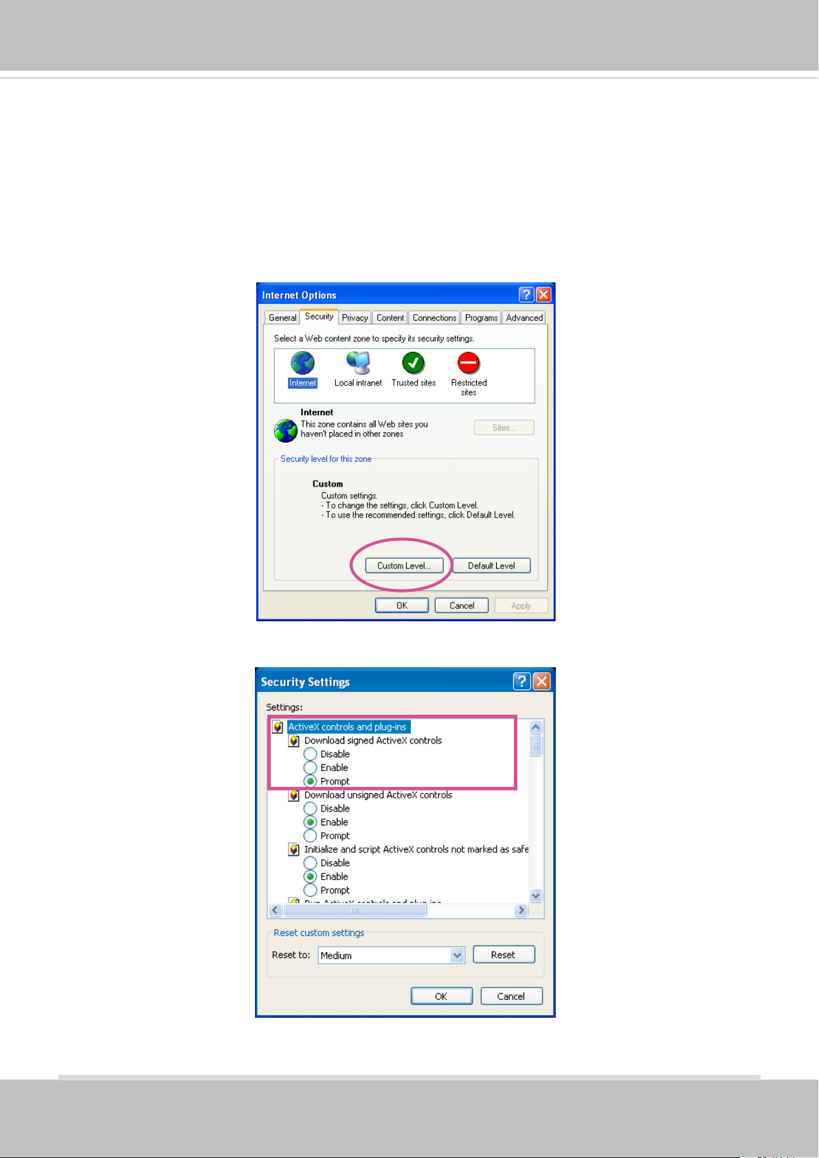
► If you see a dialog box indicating that your security settings prohibit running ActiveX
®
Controls, please enable the ActiveX
Controls for your browser�
®
1� Choose Tools > Internet Options > Security > Custom Level�
2� Look for Download signed ActiveX
®
controls; select Enable or Prompt� Click OK�
3. Refresh your web browser, then install the ActiveX
complete installation�
®
control� Follow the instructions to
User's Manual - 17
VIVOTEK
IMPORTANT:
Currently the Network Camera utilizes 32-bit ActiveX plugin� You CAN NOT open a
•
management/view session with the camera using a 64-bit IE browser�
If you encounter this problem, try execute the Iexplore.exe program from C:\Windows\
•
SysWOW64� A 32-bit version of IE browser will be installed�
On Windows 7, the 32-bit explorer browser can be accessed from here:
•
C:\Program Files (x86)\Internet Explorer\iexplore.exe
Tips
• The onscreen Java control can malfunction under the following situations:
A PC connects to different cameras that are using the same IP address (or the same
camera running different rmware versions). Removing your browser cookies will solve
this problem�
18 - User's Manual
VIVOTEK
Wireless Connection: Using the WPS Button
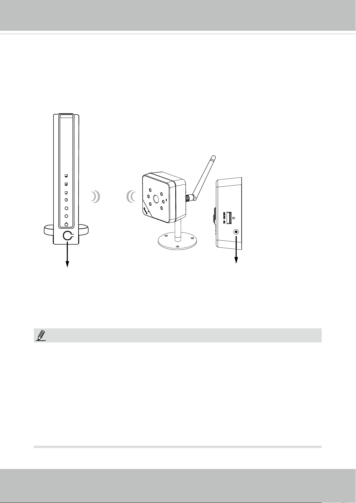
1� Make sure your AP (Access Point) and Operating System support WPS (Wi-Fi Protected
Setup) functions� WPS enables easy setup with compatible APs�
2. Disconnect your LAN cable, and connect the power cord.
3� Wait for 1 minute for the camera to boot up� Press the WPS button for 1 second� The
front panel LED should blink blue�
4� Press and hold down the WPS button on your AP (some router/AP
will have a virtual button on their management software instead)�
Refer to your AP's documentation for details using its WPS
functions�
Wireless AP
WPS
WPS
WPS Button
WPS Button
When WPS conguration is done, wireless connectivity will be established and the
security encryption, such as WEP or WPA-PSK, will be synchronized with the AP.
Use the IW2 utility to nd the camera. As for IP setting, the camera's use of DHCP or
static IP is determined by your conguration on the network camera via the web-based
conguration of rmware. The camera's default is DHCP.
NOTE:
1� It is strongly recommended to apply WPA2/AES encryption for access security�
2. WPS may not work if your AP is congured with a "hidden" SSID.
3. If no WPS-enabled AP is detected, and if the camera still can not detect an AP after 2
minutes, the wireless setup will be cancelled. If WPS conguration should fail, wireless
conguration will be cleared. You can then re-try the process above or use a wired
connection to establish a web console and manually congure the wireless settings.
4. If a camera is assigned with a xed IP outside the AP's network segment, wireless setup
will fail�
5. A wired connection always has a higher priority, and hence wireless setup will not take
effect when the RJ45 LAN port is connected� If you want to switch from wired connection
to wireless connection, disconnect the Ethernet cable and reboot the camera.
User's Manual - 19
VIVOTEK
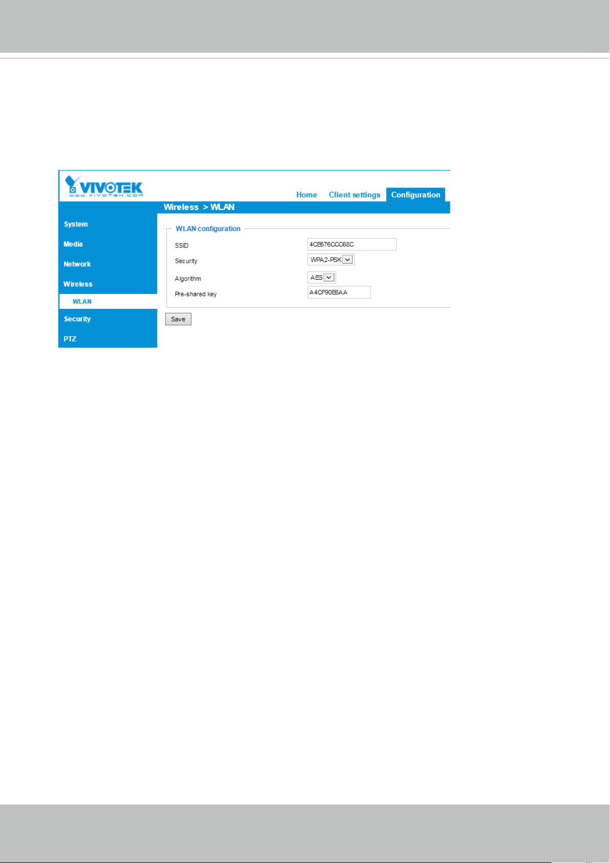
Wireless Connection: Manual Conguration
1. In addition to the use of WPS function, you can also use a wired connection to manually
set up your wireless conguration.
2� Enter the Conguration > Wireless > WLAN page� Key in the same wireless settings
as those on your router/AP (SSID, Encryption type, and Pre-shared key).
3. When done, click the Save button, disconnect the Ethernet cable and then reboot the
camera (by disconnect and then connect the power cord)� The camera should then be
connected over the wireless network. If successfully congured, the camera LED should
turn Green after 1 minute. If the camera LED does not turn Green within 2 minutes,
check your wireless conguration for errors.
20 - User's Manual
VIVOTEK
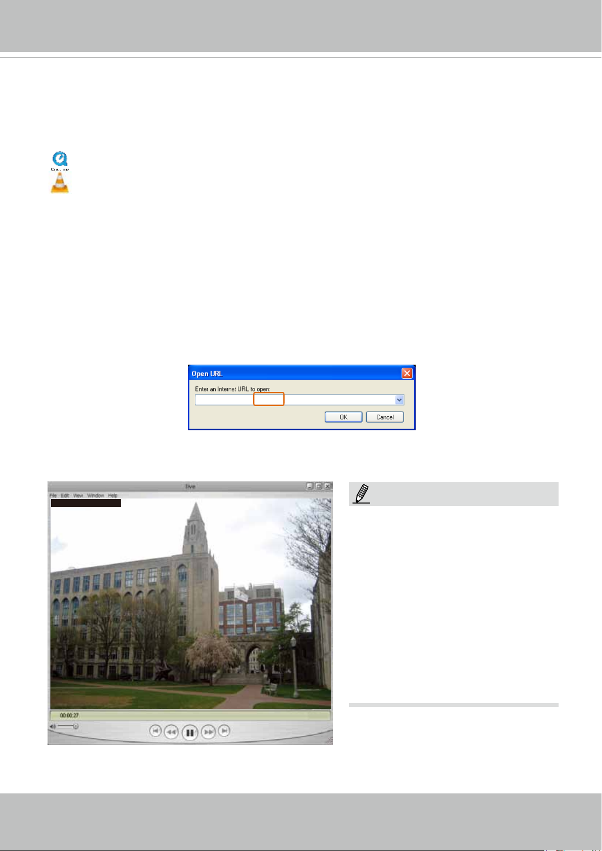
Using RTSP Players
To view the MPEG-4 streaming media using RTSP players, you can use one of the following
players that support RTSP streaming�
Quick Time Player
VLC
VLC media player
1� Launch the RTSP player you prefer�
mpegable Player
2� Choose File > Open URL� A URL dialog box will prompt�
3� The address format is: rtsp://<ip_address>:<rtsp_port>/<RTSP streaming access name for a
pvPlayer
specic video stream>
VIVOTEK’s network cameras support simultaneous playback of 2 video streams� The
streaming access names for these streams are:
Stream 1 – live.sdp,
Stream 2 – live2.sdp,
As most ISPs and players only allow RTSP streaming through port number 554, please set the
RTSP port to 554. For more information, please refer to RTSP Streaming on page 68.
For example:
rtsp://192.168.5.151:554/live.sdp
4� The live video will be displayed in your player�
For more information on how to configure the RTSP access name, please refer to RTSP
Streaming on page 68 for details�
Video 16:38:01 2012/01/25
NOTE:
Quick Time player only supports play-
back of H.264 stream, and not the
MJPEG stream� In terms of audio co-
dec, Quick Time only supports AAC.
Since this camera only supports G�711
codec, audio is not available on Quick
Time�
VLC player supports H�264/MPEG-4/
MJPEG, and all audio codecs supported by all VIVOTEK’s cameras�
User's Manual - 21
VIVOTEK
Using 3GPP-compatible Mobile Devices
To view the streaming media through 3GPP-compatible mobile devices, make sure the Network
Camera can be accessed over the Internet� For more information on how to set up the Network
Camera over the Internet, please refer to Setup the Network Camera over the Internet on page
12�
To utilize this feature, please check the following settings on your Network Camera:
1. Because most players on 3GPP mobile phones do not support RTSP authentication, make
sure the authentication mode of RTSP streaming is set to disable�
For more information, please refer to RTSP Streaming on page 68.
2. As the the bandwidth on 3G networks is limited, you will not be able to use a large video size.
Please set the video and audio streaming parameters as listed below�
For more information, please refer to Stream settings on page 53�
Video Mode MPEG-4
Frame size 176 x 144
Maximum frame rate 5 fps
Intra frame period 1S
Video quality (Constant bit rate) 40kbps
Audio type (GSM-AMR) 12.2kbps
3. As most ISPs and players only allow RTSP streaming through port number 554, please set
the RTSP port to 554. For more information, please refer to RTSP Streaming on page 68.
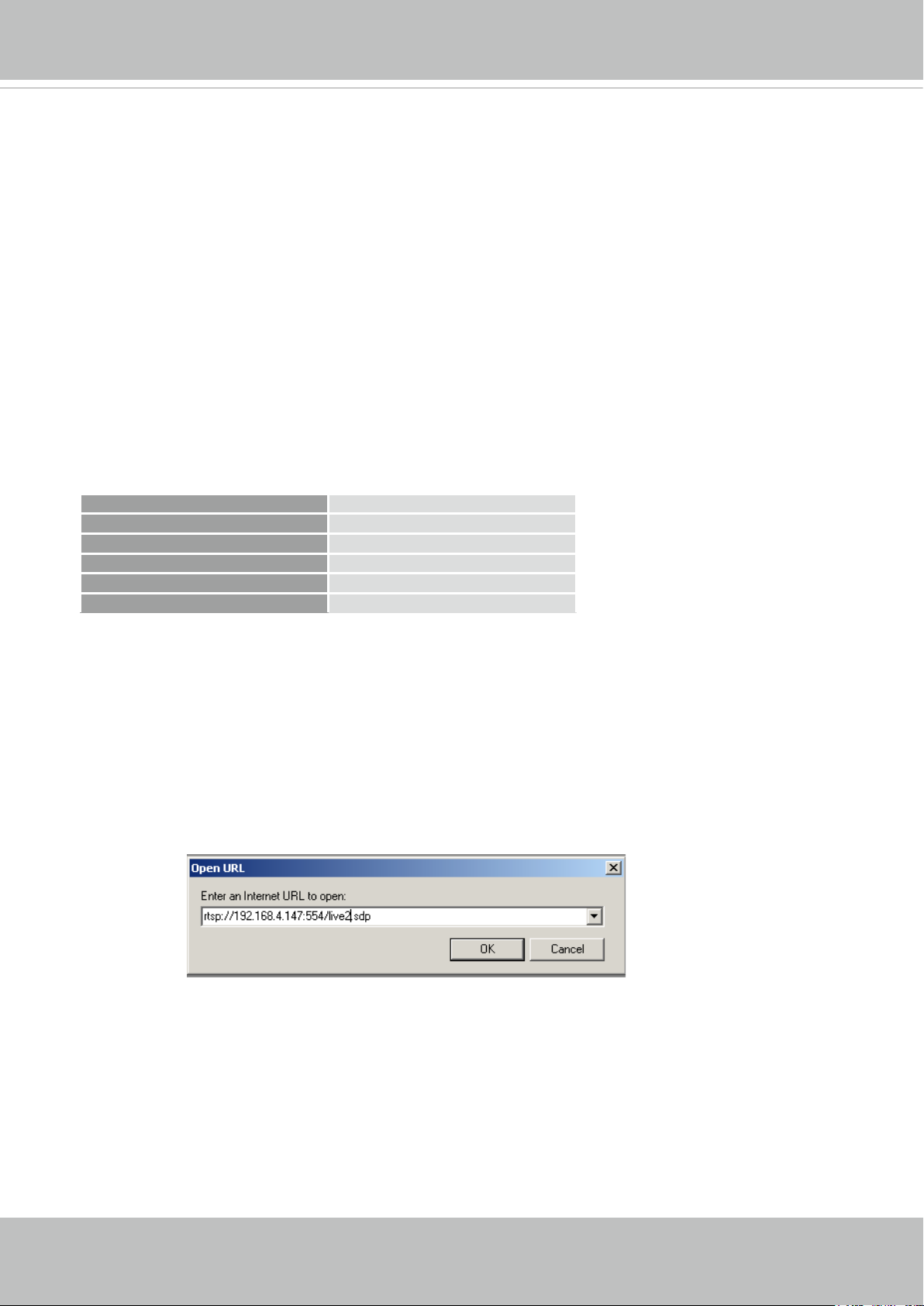
4. Launch the player on the 3GPP-compatible mobile devices (e.g., VLC Player).
5� Type the following URL commands into the player�
The address format is rtsp://<public ip address of your camera>:<rtsp port>/<RTSP streaming
access name for stream # with small frame size and frame rate>�
For example:
You can configure Stream #2 into the suggested stream settings as listed above for live
viewing on a mobile device�
22 - User's Manual
VIVOTEK
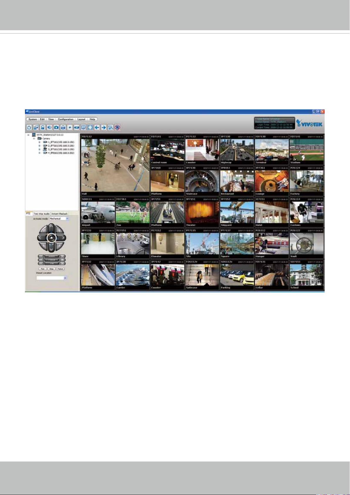
Using VIVOTEK Recording Software
The product software CD also contains an ST7501 recording software, allowing simultaneous
monitoring and video recording for multiple Network Cameras� Please install the recording
software; then launch the program to add the Network Camera to the Channel list� For detailed
information about how to use the recording software, please refer to the user’s manual of the
software or download it from http://www�vivotek�com�
User's Manual - 23
VIVOTEK
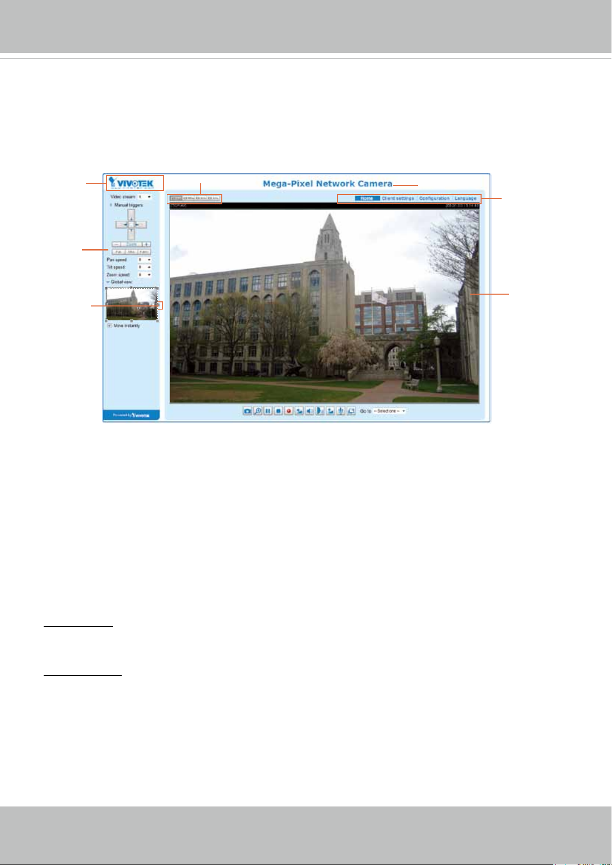
Main Page
This chapter explains the layout of the main page� It is composed of the following sections:
VIVOTEK INC. Logo, Host Name, Camera Control Area, Configuration Area, Menu, and Live
Video Window�
VIVOTEK INC.
Logo
Camera Control
Area
Hide Button
Resize Buttons
Host Name
Configuration
Area
Live View Window
VIVOTEK INC. Logo
Click this logo to visit the VIVOTEK website�
Host Name
The host name can be customized to t your needs. For more information, please refer to System on page 34.
Camera Control Area
Video Stream: This Network Camera supports multiple streams (stream 1 ~ 2) simultaneously� You can
select either one for live viewing. For more information about multiple streams, please refer to page 81
for detailed information�
Manual Trigger: Click to enable/disable an event trigger manually� Please configure an event setting
on Application page before enable this function. A total of 3 event settings can be congured. For more
information about event setting, please refer to page 91. If you want to hide this item on the homepage,
please go to Conguration> System > Homepage Layout > General settings > Customized button
to deselect “show manual trigger button”�
24 - User's Manual
VIVOTEK
Conguration Area
Client Settings: Click this button to access the client setting page. For more information, please refer to
Client Settings on page 29�
Conguration: Click this button to access the conguration page of the Network Camera. It is suggested
that a password be applied to the Network Camera so that only the administrator can configure the
Network Camera. For more information, please refer to Conguration on page 33.
Language: Click this button to choose a language for the user interface� Language options are available
in: English, Deutsch, Español, Français, Italiano,
日本語
, Português,
簡体中文
, and
繁體中文
� Please
note that you can also change a language on the Conguration page; please refer to page 33.
Hide Button
You can click the hide button to hide the control panel or display the control panel�
Resize Buttons
:
Click the Auto button, the video cell will resize automatically to t the monitor.
Click 100% is to display the original homepage size�
Click 50% is to resize the homepage to 50% of its original size�
Click 25% is to resize the homepage to 25% of its original size�
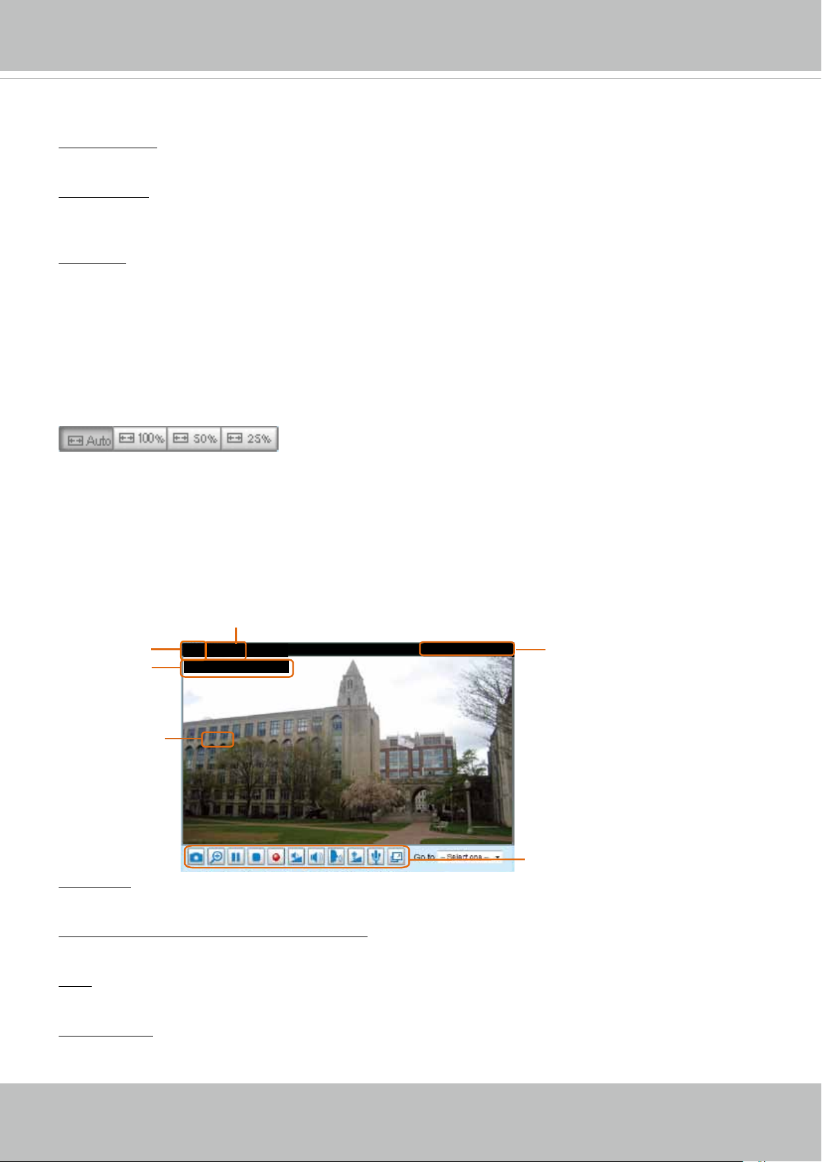
Live Video Window
■ The following window is displayed when the video mode is set to H�264 / MPEG-4:
H.264 / MPEG-4 Protocol and Media Options
Video Title
Title and Time
Zoom Indicator
Video (TPC-AV)
Video 17:08:56 2012/11/25
x4.0
Video Title: The video title can be congured. For more information, please refer to Video Settings on
page 53�
H�264 / MPEG-4 Protocol and Media Options: The transmission protocol and media options for H�264 /
MPEG-4 video streaming. For further conguration, please refer to Client Settings on page 29.
2012/11/25 17:08:56
Time
Video and Audio Control Buttons
Time: Display the current time. For further conguration, please refer to Media > Image > Genral settings
on page 46�
Title and Time: The video title and time can be stamped on the streaming video. For further conguration,
please refer to Media > Image > General settings on page 46�
User's Manual - 25
VIVOTEK
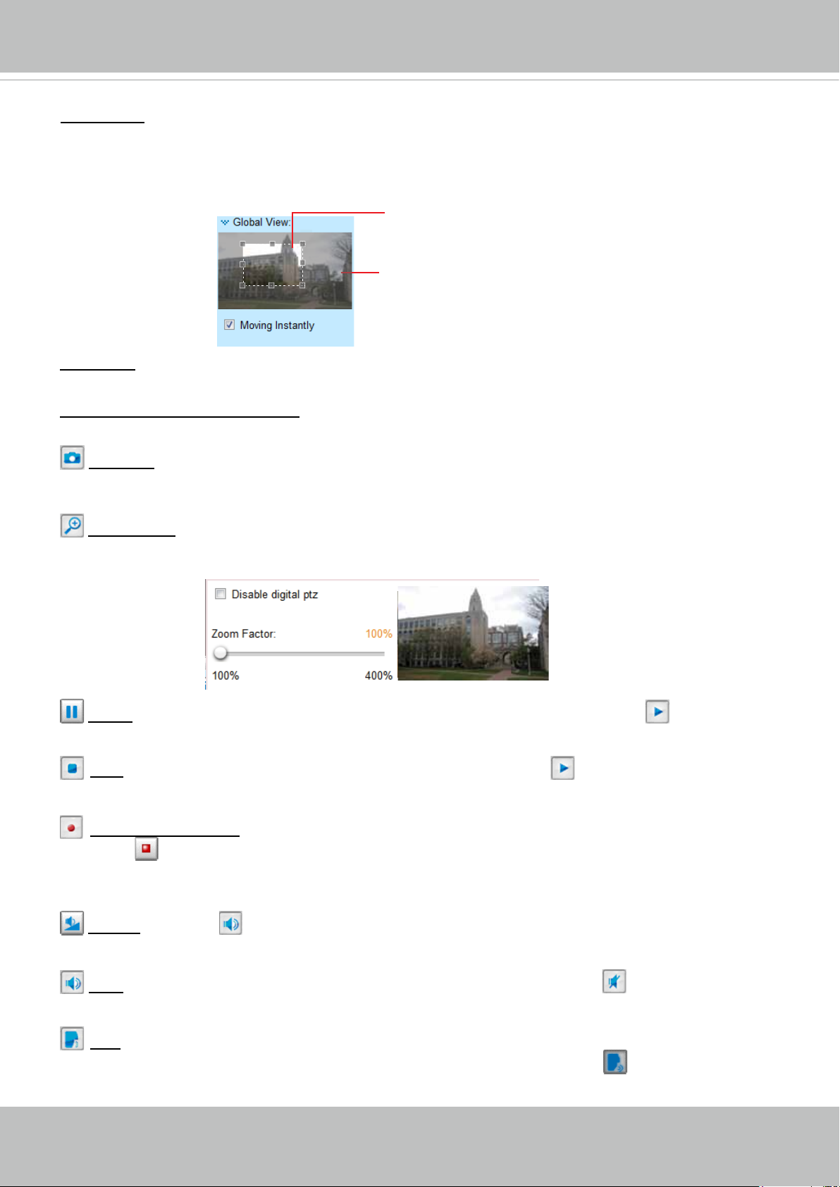
Global View: Click on this item to display the Global View window� The Global View window contains a
full view image (the largest frame size of the captured video) and a oating frame (the viewing region of
the current video stream). The oating frame allows users to control the e-PTZ function (Electronic Pan/
Tilt/Zoom). For more information about e-PTZ operation, please refer to E-PTZ Operation on page 88.
For more information about how to set up the viewing region of the current video stream, please refer to
page 88�
The viewing region of
the current video
stream
The largest frame size
PTZ Panel: This Network Camera supports both “digital“ (e-PTZ) pan/tilt/zoom control� Please refer to
PTZ settiings on page 88 for detailed information�
Video and Audio Control Buttons: Depending on the Network Camera model and Network Camera
conguration, some buttons may not be available.
Snapshot: Click this button to capture and save still images� The captured images will be displayed
in a pop-up window� Right-click the image and choose Save Picture As to save it in JPEG (*�jpg) or BMP
(*�bmp) format�
Digital Zoom: Click and uncheck “Disable digital zoom” to enable the zoom operation� The navigation
screen indicates the part of the image being magnied. To control the zoom level, drag the slider bar. To
move to a different area you want to magnify, drag the navigation screen.
Pause: Pause the transmission of the streaming media� The button becomes the Resume button
after clicking the Pause button�
Stop: Stop the transmission of the streaming media� Click the Resume button to continue
transmission�
Start MP4 Recording: Click this button to record video clips in MP4 file format to your computer�
Press the
Stop MP4 Recording button to end recording. When you exit the web browser, video
recording stops accordingly. To specify the storage destination and le name, please refer to MP4 Saving
Options on page 30 for details�
Volume: When the Mute function is not activated, move the slider bar to adjust the volume on the
local computer�
Mute: Turn off the volume on the local computer� The button becomes the Audio On button after
clicking the Mute button�
Talk: Click this button to talk to people around the Network Camera� Audio will project from
the external speaker connected to the Network Camera� Click this button
again to end talking
transmission�
26 - User's Manual
VIVOTEK
Mic Volume: When the Mute function is not activated, move the slider bar to adjust the
microphone volume on the local computer�
Mute: Turn off the Mic volume on the local computer� The button becomes the Mic On button
after clicking the Mute button�
Full Screen: Click this button to switch to full screen mode� Press the “Esc” key to switch back to normal
mode�
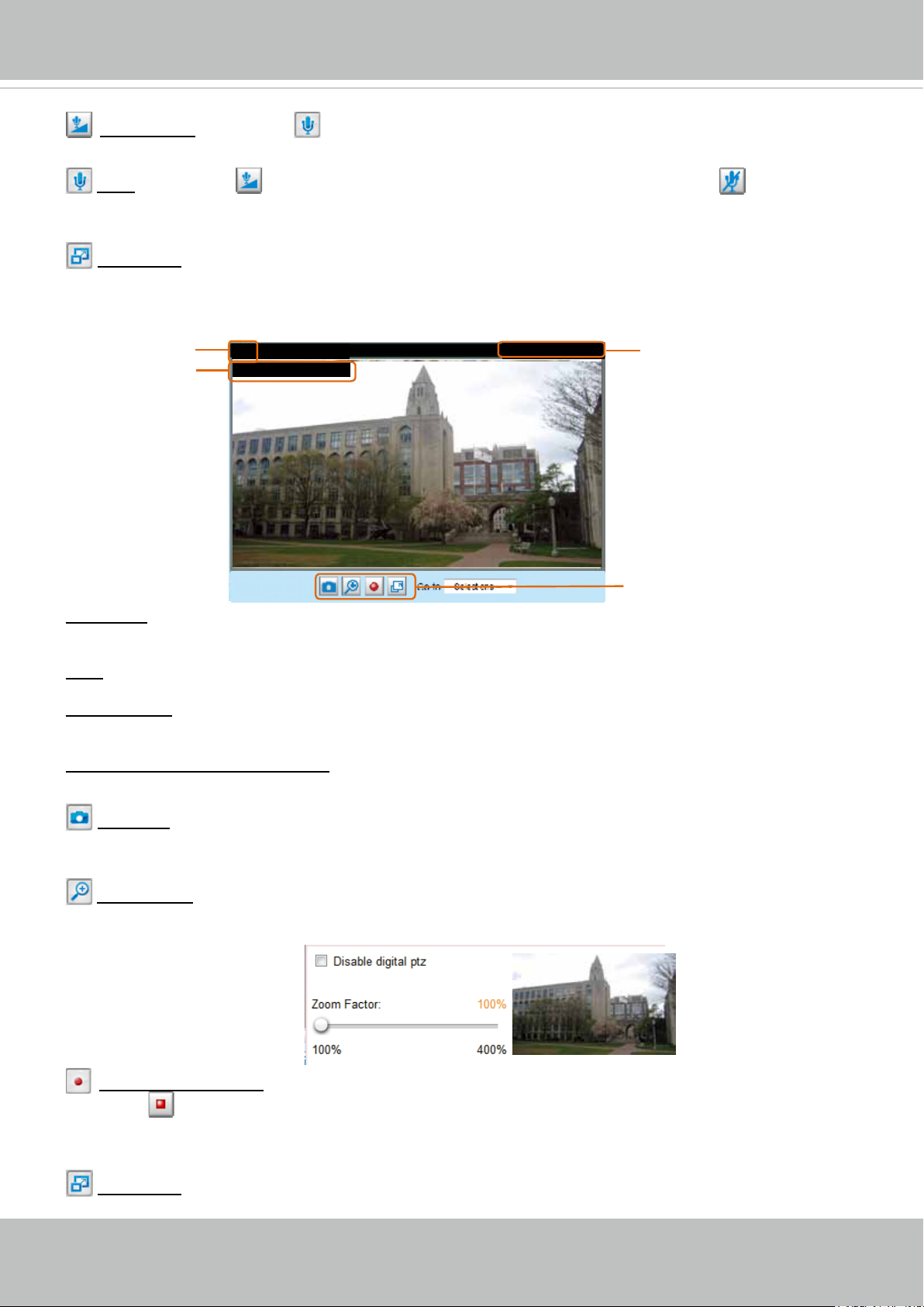
■ The following window is displayed when the video mode is set to MJPEG:
Video Title
Title and Time
Video (HTTP-V)
Video 17:08:56 2012/06/25
2012/06/25 17:08:56
Time
Video Control Buttons
Video Title: The video title can be congured. For more information, please refer to Media > Image on
page 46�
Time: Display the current time. For more information, please refer to Media > Image on page 46.
Title and Time: Video title and time can be stamped on the streaming video. For more information, please
refer to Media > Image on page 46
�
Video and Audio Control Buttons: Depending on the Network Camera model and Network Camera
conguration, some buttons may not be available.
Snapshot: Click this button to capture and save still images� The captured images will be displayed
in a pop-up window� Right-click the image and choose Save Picture As to save it in JPEG (*�jpg) or BMP
(*�bmp) format�
Digital Zoom: Click and uncheck “Disable digital zoom” to enable the zoom operation� The navigation
screen indicates the part of the image being magnied. To control the zoom level, drag the slider bar. To
move to a different area you want to magnify, drag the navigation screen.
Start MP4 Recording: Click this button to record video clips in MP4 file format to your computer�
Press the
Stop MP4 Recording button to end recording. When you exit the web browser, video
recording stops accordingly. To specify the storage destination and le name, please refer to MP4 Saving
Options on page 30 for details�
Full Screen: Click this button to switch to full screen mode� Press the “Esc” key to switch back to normal
mode�
User's Manual - 27
VIVOTEK
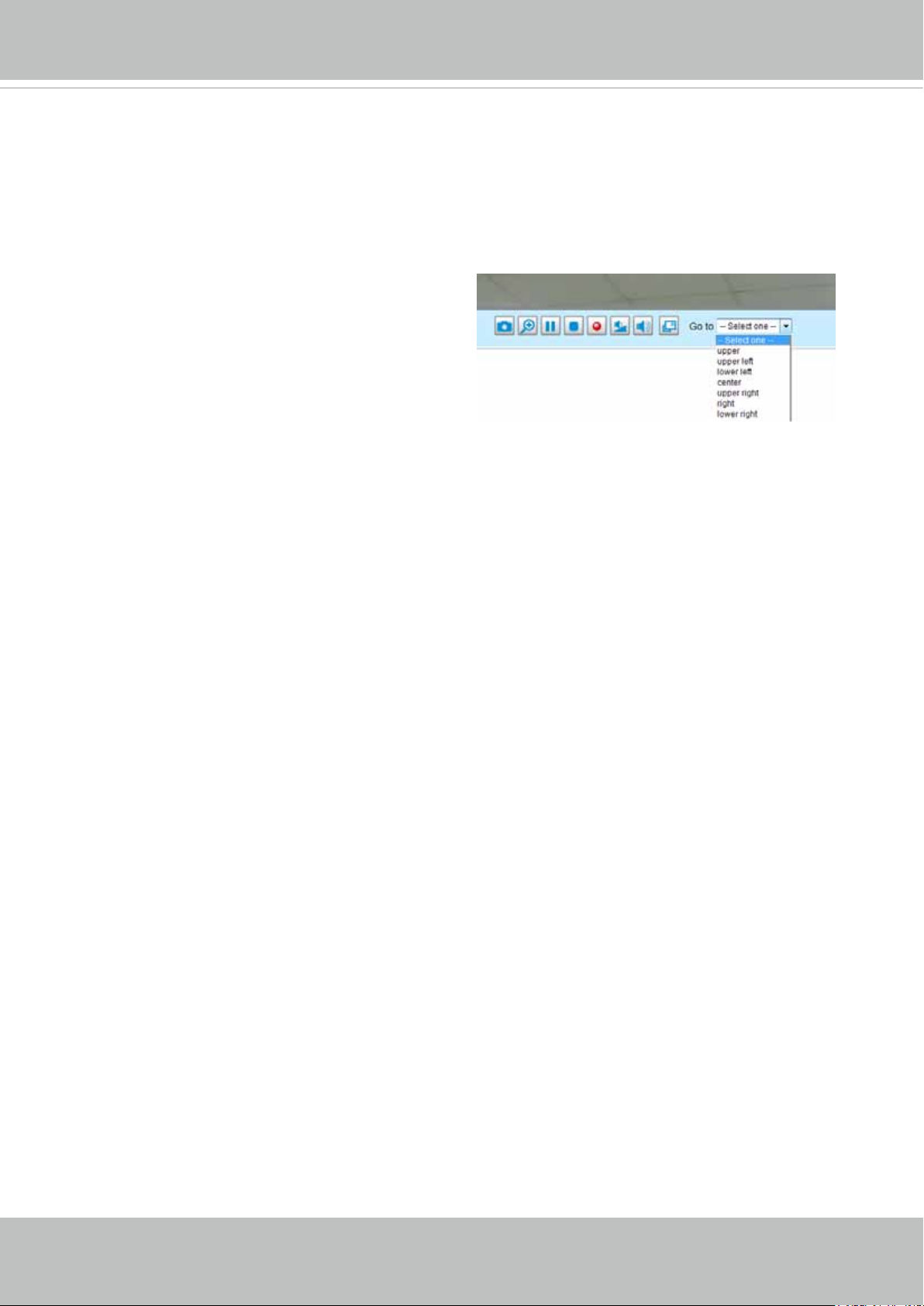
Go to
If you congured and chose to display a smaller region of interest from out of a maximum
image frame, you can congure different areas within the frame as preset points, and use
this menu to move to a location�
28 - User's Manual
VIVOTEK
Client Settings
This chapter explains how to select the stream transmission mode and saving options on the
local computer. When completed with the settings on this page, click Save on the page bottom
to enable the settings�
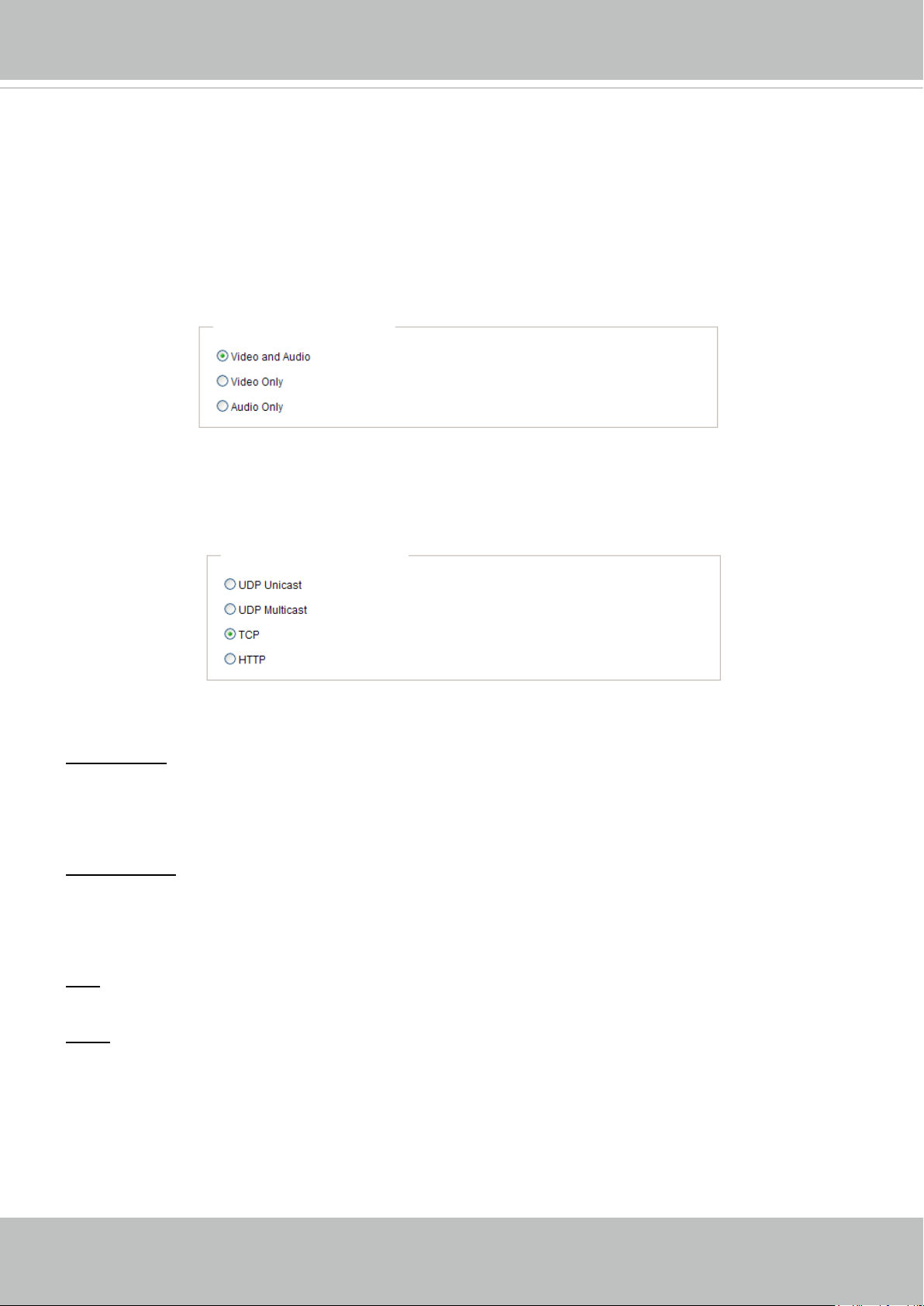
H.264 Media Options
H.264 Media Options
Select to stream video or audio data or both� This is enabled only when the video mode is set to H�264 or
MPEG-4�
H.264 Protocol Options
H.264 Protocol Options
Depending on your network environment, there are four transmission modes of H.264 or MPEG-4
streaming:
UDP unicast: This protocol allows for more real-time audio and video streams. However, network
packets may be lost due to network burst trafc and images may be broken. Activate UDP connection
when occasions require time-sensitive responses and the video quality is less important� Note that each
unicast client connecting to the server takes up additional bandwidth and the Network Camera allows up
to ten simultaneous accesses�
UDP multicast: This protocol allows multicast-enabled routers to forward network packets to all clients
requesting streaming media� This helps to reduce the network transmission load of the Network Camera
while serving multiple clients at the same time. Note that to utilize this feature, the Network Camera must
be configured to enable multicast streaming at the same time. For more information, please refer to
RTSP Streaming on page 68�
TCP: This protocol guarantees the complete delivery of streaming data and thus provides better video
quality� The downside of this protocol is that its real-time effect is not as good as that of the UDP protocol�
HTTP: This protocol allows the same quality as TCP protocol without needing to open specic ports for
streaming under some network environments� Users inside a firewall can utilize this protocol to allow
streaming data through�
User's Manual - 29
VIVOTEK
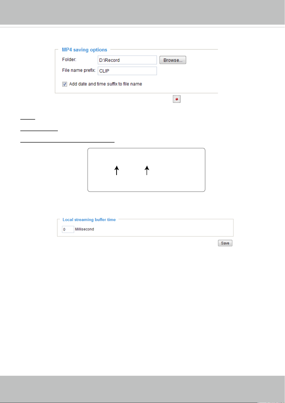
MP4 Saving Options
Users can record live video as they are watching it by clicking Start MP4 Recording on the main
page. Here you can specify the storage destination and le name.
Folder: Specify a storage destination for the recorded video les.
File name prex: Enter the text that will be appended to the front of the video le name.
Add date and time sufx to the le name: Select this option to append the date and time to the end of the
le name.
CLIP_20110628-180853
File name prefix
Date and time suffix
The format is: YYYYMMDD_HHMMSS
Local Streaming Buffer Time
Due to the unsteady bandwidth ow, the live streaming may lag and not be very smoothly. If you enable
this option, the live streaming will be stored on the cache memory of the PC having a web session with
the camera for a few seconds before being played on the live viewing window� This helps you see the
streaming more smoothly. If you enter 3000 Millisecond, the streaming will delay for 3 seconds.
30 - User's Manual
 Loading...