

Page 1

AW-GEV-107A-130
AW-GEV-267A-370
L2 Managed PoE Switch
User Manual
2017, Manufacture Corporation. All rights reserved. All brand and product names are trademarks or registered
trademarks of their respective companies.
User Manual rev. 1.0. Mar. 2017
Rev. 1.0
i
1
Page 2

Copyright
About This Manual
Copyright © 2017 VIVOTEK Inc. All rights reserved.
The products and programs described in this User’s Manual are licensed products of
VIVOTEK Inc., This User’s Manual contains proprietary information protected by
copyright, and this User’s Manual and all accompanying hardware, software and
documentation are copyrighted. No parts of this User’s manual may be copied,
photocopied, reproduced, translated or reduced to any electronic medium or
machine-readable from by any means by electronic or mechanical. Including
photocopying, recording, or information storage and retrieval systems, for any purpose
other than the purchaser’s personal use, and without the prior express written
permission of VIVOTEK Inc.
Purpose
Audience
This manual gives specific information on how to operate and use the management
functions of the AW-GEV-107A and -267A
The Manual is intended for use by network administrators who are responsible for
operating and maintaining network equipment; consequently, it assumes a basic
working knowledge of general switch functions, the Internet Protocol (IP), and web
management (HTTP/HTTPs).
User Manual rev. 1.0. Mar. 2017
ii
2
Page 3

Table of Contents
ABOUT THIS MANUAL...........................................................................................................II
INTRODUCTION.......................................................................................................................1
CHAPTER 1 OPERATION OF WEB-BASED MANAGEMENT.................................2
CHAPTER 2 SYSTEM CONFIGURATION....................................................................6
2-1 System.................................................................................................................................................6
2-1.1 Information.............................................................................................................................................6
2-1.2 IP..............................................................................................................................................................7
2-1.3 NTP........................................................................................................................................................10
2-1.4 Time.......................................................................................................................................................11
2-1.5 Log.........................................................................................................................................................14
2-2 Green Ethernet.................................................................................................................................15
2-3 Ports Configuration.........................................................................................................................18
2-3.1 Ports......................................................................................................................................................18
2-3.2 Ports Description.................................................................................................................................20
2-4 DHCP.................................................................................................................................................21
2-4.1 Server....................................................................................................................................................21
2-4.2 Snooping..............................................................................................................................................26
2-5 Security.............................................................................................................................................28
2-5.1 Switch....................................................................................................................................................28
2-5.2 Network................................................................................................................................................54
2-5.3 AAA........................................................................................................................................................81
2-6 Aggregation.....................................................................................................................................84
2-6.1 Static......................................................................................................................................................84
2-6.2 LACP......................................................................................................................................................86
2-7 Loop Protection...............................................................................................................................88
2-8 Spanning Tree..................................................................................................................................90
2-8.1 Bridge Setting......................................................................................................................................90
2-8.2 MSTI Mapping......................................................................................................................................93
2-8.3 MSTI Priorities......................................................................................................................................95
2-8.4 CIST Ports..............................................................................................................................................96
2-8.5 MSTI Ports............................................................................................................................................99
2-9 IPMC.................................................................................................................................................101
2-9.1 IGMP Snooping..................................................................................................................................101
2-10.1 LLDP Configuration.........................................................................................................................106
2-10.2 LLDP-MED Configuration...............................................................................................................109
2- 11 PoE.................................................................................................................................................116
2- 11.1 Configuration..................................................................................................................................116
2- 11.2 Power Delay....................................................................................................................................119
2- 11.3 Scheduling............................................................................................................................... ........120
2- 11.4 Auto Checking................................................................................................................................122
2-12 MAC Table.....................................................................................................................................124
2-13 VLANs............................................................................................................................................127
2-14 Private VLANs...............................................................................................................................131
2-14.1 VLAN Membership..........................................................................................................................131
2-14.2 Port Isolation....................................................................................................................................133
2-15 VCL.................................................................................................................................................134
2-15.1 MAC-based VLAN............................................................................................................................134
2-15.2 Protocol -based VLAN....................................................................................................................136
2-15.3 IP Subnet-based VLAN...................................................................................................................139
2-16 VOICE VLAN..................................................................................................................................140
2-16.1 Configuration............................................................................................................................... ....140
2-16.2 OUI....................................................................................................................................................142
User Manual rev. 1.0. Mar. 2017
ii
2
Page 4

2-17 QoS.................................................................................................................................................143
2-17.1 Port Classification............................................................................................................................143
2-17.2 Port Policing.....................................................................................................................................145
2-17.4 Port Schedulers................................................................................................................................146
2-17.5 Port Shaping.....................................................................................................................................149
2-17.6 Port Tag Remarking.........................................................................................................................152
2-17.7 Port DSCP.........................................................................................................................................155
2-17.8 DSCP-Based QoS.............................................................................................................................157
2-17.9 DSCP Translation..............................................................................................................................159
2-17.10 DSCP Classification........................................................................................................................161
2-17.11 QoS Control List Configuration...................................................................................................163
2-17.12 Storm Control................................................................................................................................167
2-18 Mirror.............................................................................................................................................168
2-19 UPnP..............................................................................................................................................170
2-20 Switch2go......................................................................................................................................172
2-20.1 Switch2go setting............................................................................................................................172
2-20.2 User Link Management...................................................................................................................174
2-20.3 Port Name Service...........................................................................................................................175
2-21 SMTP Configuration.....................................................................................................................176
CHAPTER 3. MONITOR.........................................................................................178
3-1 System..............................................................................................................................................178
3-1.1 Information.........................................................................................................................................178
3-1.2 IP Status..............................................................................................................................................181
3-1.3 Log.......................................................................................................................................................183
3-1.4 Detailed Log.......................................................................................................................................185
3-2 Green Ethernet................................................................................................................................186
3-2.1 Port Power Savings............................................................................................................................186
3-3 Ports.................................................................................................................................................187
3-3.1 Traffic Overview.................................................................................................................................187
3-3.2 Qos Statistics......................................................................................................................................189
3-3.3 QCL Status..........................................................................................................................................190
3-3.4 Detailed Statistics..............................................................................................................................192
3-3.5 SFP Information.................................................................................................................................195
3-4 DHCP................................................................................................................................................197
3-4.1 Server..................................................................................................................................................197
3-4.2 Snooping Table..................................................................................................................................200
3-4.3 Detailed Statistics..............................................................................................................................201
3-5 Security............................................................................................................................................203
3-5.2 Network..............................................................................................................................................203
3-5.3 AAA......................................................................................................................................................218
3-5.4 Switch..................................................................................................................................................225
3-6 LACP.................................................................................................................................................234
3-6.1 System Status.....................................................................................................................................234
3-6.2 Port Status..........................................................................................................................................235
3-6.3 Port Statistics......................................................................................................................................237
3-7 Loop Protection..............................................................................................................................238
3-8 Spanning Tree.................................................................................................................................239
3-8.1 Bridge Status......................................................................................................................................239
3-8.2 Port Status..........................................................................................................................................240
3-8.3 Port Statistics......................................................................................................................................241
3-9 IPMC.................................................................................................................................................242
3-9.1 IGMP Snooping..................................................................................................................................242
3-10 LLDP...............................................................................................................................................246
3-10.1 Neighbour........................................................................................................................................246
3-10.2 LLDP-MED Neighbour....................................................................................................................248
User Manual rev. 1.0. Mar. 2017
iii
3
Page 5

3-10.3 PoE.....................................................................................................................................................251
3-10.4 EEE.....................................................................................................................................................253
3-10.5 Port Statistics....................................................................................................................................255
3-11 PoE Statistics.................................................................................................................................257
3-12 MAC Table.....................................................................................................................................259
3-13 VLANs............................................................................................................................................261
3-13.1 VLAN Membership..........................................................................................................................261
3-13.2 VLAN Port.........................................................................................................................................263
3-14 VCL.................................................................................................................................................265
3-14.1 MAC-based VLAN............................................................................................................................265
3-14.2 Protocol-based VLAN.....................................................................................................................266
3-14.3 IP Subnet-based VLAN...................................................................................................................269
CHAPTER 4. DIAGNOSTICS......................................................................................270
4-1 Ping..................................................................................................................................................270
4-2 Ping6................................................................................................................................................272
4-3 VeriPHY............................................................................................................................................274
4-4 Traceroute........................................................................................................................................275
CHAPTER 5. MAINTENANCE...................................................................................276
5-1 Restart Device.................................................................................................................................276
5-2 Factory Defaults..............................................................................................................................277
5-3 Firmware..........................................................................................................................................278
5-3.1 Firmware upgrade.............................................................................................................................278
5-3.2 Firmware Selection............................................................................................................................278
5-4 Configuration..................................................................................................................................279
5-4.1 Save startup-config...........................................................................................................................280
5-4.2 Upload.................................................................................................................................................281
5-4.3 Download...........................................................................................................................................282
5-4.4 Activate...............................................................................................................................................283
5-4.5 Delete..................................................................................................................................................284
CHAPTER 6 SURVEILLANCE - MANAGEMENT.....................................................285
6.1MANAGEMENT...................................................................................................................286
Surveillance mode.................................................................................................................................286
6.2DEVICELIST.........................................................................................................................287
6.3VVTKCAMERA&ENCODER................................................................................................288
6‐3‐1CameraUpgrade..............................................................................................................................288
6‐3‐2CameraConfigure.............................................................................................................................290
6‐3‐2‐1ConfigExport.....................................................................................................................................290
6‐3‐2‐2ConfigImport....................................................................................................................................291
6‐3‐2‐3ConfigFiles........................................................................................................................................292
CHAPTER 7 SURVEILLANCE - GRAPHICAL MONITORING .............................. 293
7‐1Topo l o g yView.....................................................................................................................................293
7‐2FloorView...........................................................................................................................................303
7‐3MapView............................................................................................................................................307
CHAPTER 8 SURVEILLANCE - MAINTENANCE ............................................. 309
8‐1FloorImage.........................................................................................................................................308
8‐2Diagnostics..........................................................................................................................................310
User Manual rev. 1.0. Mar. 2017
iv
4
Page 6

Revision History
Release Date Revision
V1.00 2017/03/06 A1
User Manual rev. 1.0. Mar. 2017
v
5
Page 7

INTRODUCTION
Overview
AW-GEV-107A and -267A L2+ Managed PoE+ Switch is a next-generation Ethernet Switch
offering powerful L2 features, Layer 3 Static Route, better PoE functionality and usability that delivers
the cost-effectively business and transports Ethernet services via fiber or copper connections.
AW-GEV-107A and -267A delivers 10 or 24 (10M/100M/1G) RJ45 and PoE+ (Support 802.3at/af,
and total up to 130W or 370W) ports and 2 Combo GbE RJ45/SFP ports. AW-GEV-107A and -267A
provides high HW performance and environment flexibility for SMBs and Enterprises.
AW-GEV-107A and -267A is ideal to deliver management simplicity, optimum user experience,
and lower cost. The embedded Device Managed System is designed to be extremely
easy-to-use/manage/install IP Phone, IP Cam, or Wifi-AP for Enterprise Applications.
L2+ features provide easier manageability, basic security and QoS
Built-in Surveillance feature
DHCP Server
IPv4/IPv6 L3 static route
PoE Port configuration and scheduling
802.3at high power PoE plus standard
IEEE 802.3az EEE Energy Efficient Ethernet standard for green Ethernet application
Overview of this user’s manual
Chapter 1 “Operation of Web-based Management”
Chapter 2 “Configuration”
Chapter 3 “Monitor”
Chapter 4 “Diagnostics”
Chapter 5 “Maintenance”
NOTE:
For users who use this switch in a surveillance application, you can go directly to
Chapter 6 through Chapter 8 for information directly related to surveillance
deployments.
1
Publication date: Nov., 2016
Revision A1
Page 8
Chapter 1 Operation of Web-based Management
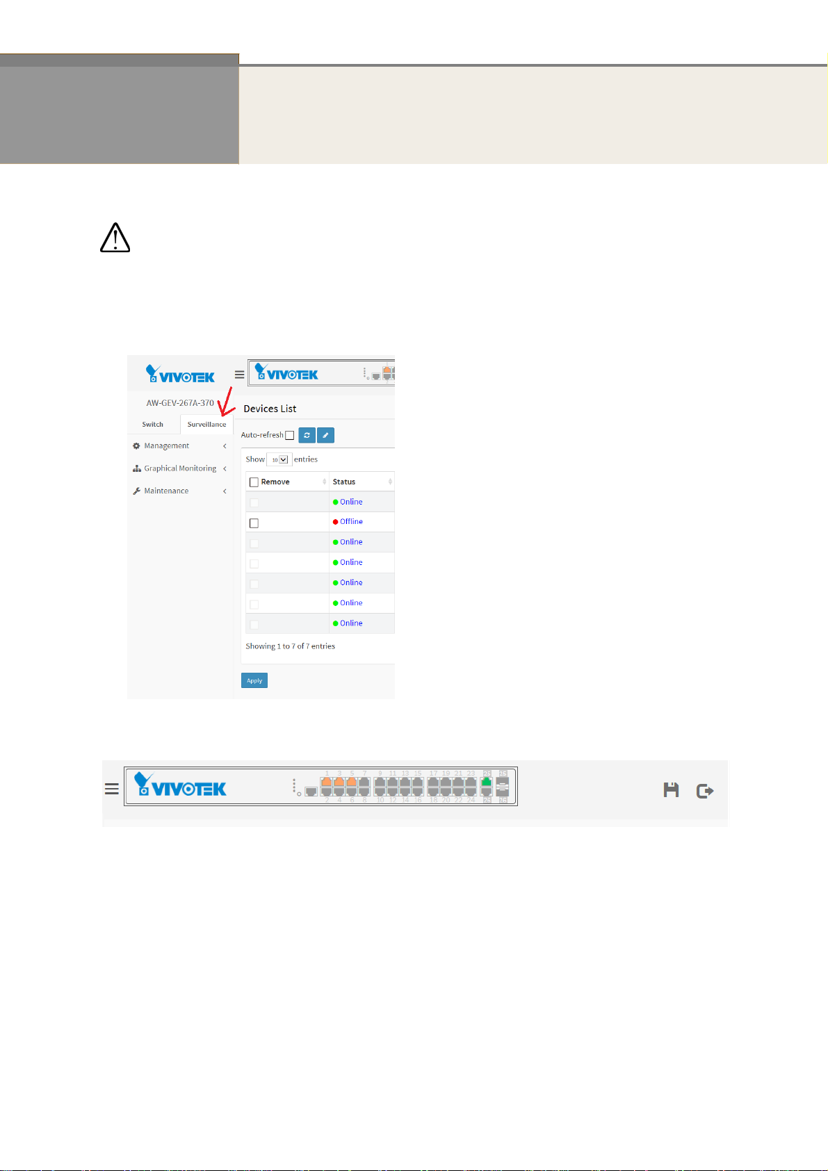
IMPORTANT:
1. It is recommended to use IE10 or IE11 to open a web console with the PoE switch.
2. This PoE switch is specifically d esigned for surve illance applications. It comes with an integrated
Surveillance interface for ease of configuration. The Surveillance interface is accessed through
a tabbed menu, and the configuration changes made in its window have a higher priority than
those in the Switch configuration menus.
3. You should save the configuration changes made on the Surveillance menus before leaving the
web page. Otherwise, your configuration changes will be lost. The save button is located on the
upper right corner of the screen.
This chapter instructs you how to configure and manage the PoE L2 switch through the web user
interface.
the status of the switch, including MIBs status, each port activity, Spanning tree status, port
aggregation status, multicast traffic, VLAN and priority status, even illegal access record and so on.
With this facility, you can easily access and monitor through any one port of the switch a ll
Initial
Configuration
This chapter instructs you how to configure and manage the AW-GEV-107A and
-267A
through the web user interface. With this facility, you can easily access and
monitor through any one port of the switch all the status of the switch, including MIBs
status, each port activity, Spanning tree status, port aggregation status, multicast
traffic, VLAN and priority status, even illegal access record and so on.
T
he default values of the AW-GEV-107A and -267A are listed in the table below:
2
Publication date: Nov., 2016
Revision A1
Page 9
IP Address DHCP client
Subnet Mask 255.255.255.0
Default
Username admin
Password admin
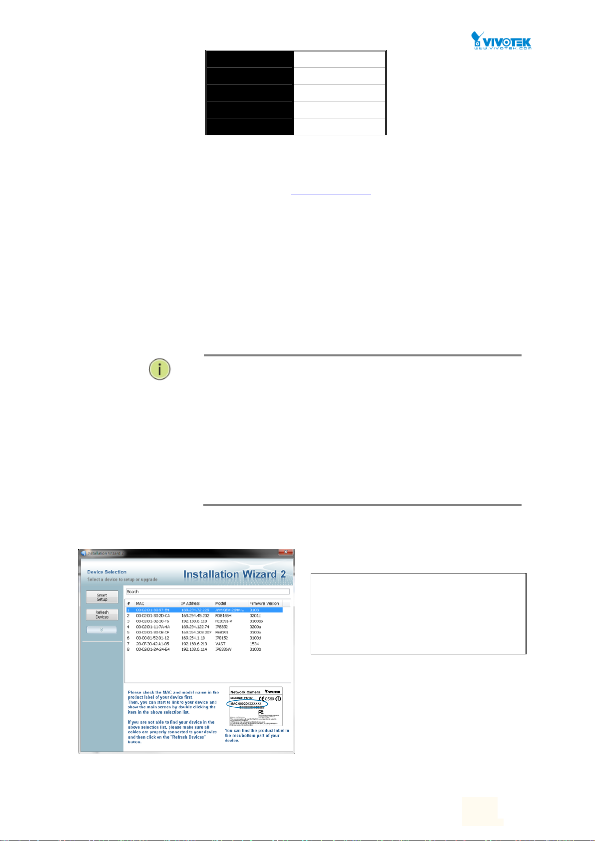
You can use VIVOTEK's IW2 utility to locate the PoE switch. After the
AW-GEV-107A and -267A has been finished configuration the it interface, you can
browse it. For instance, type http://192.168.1.1
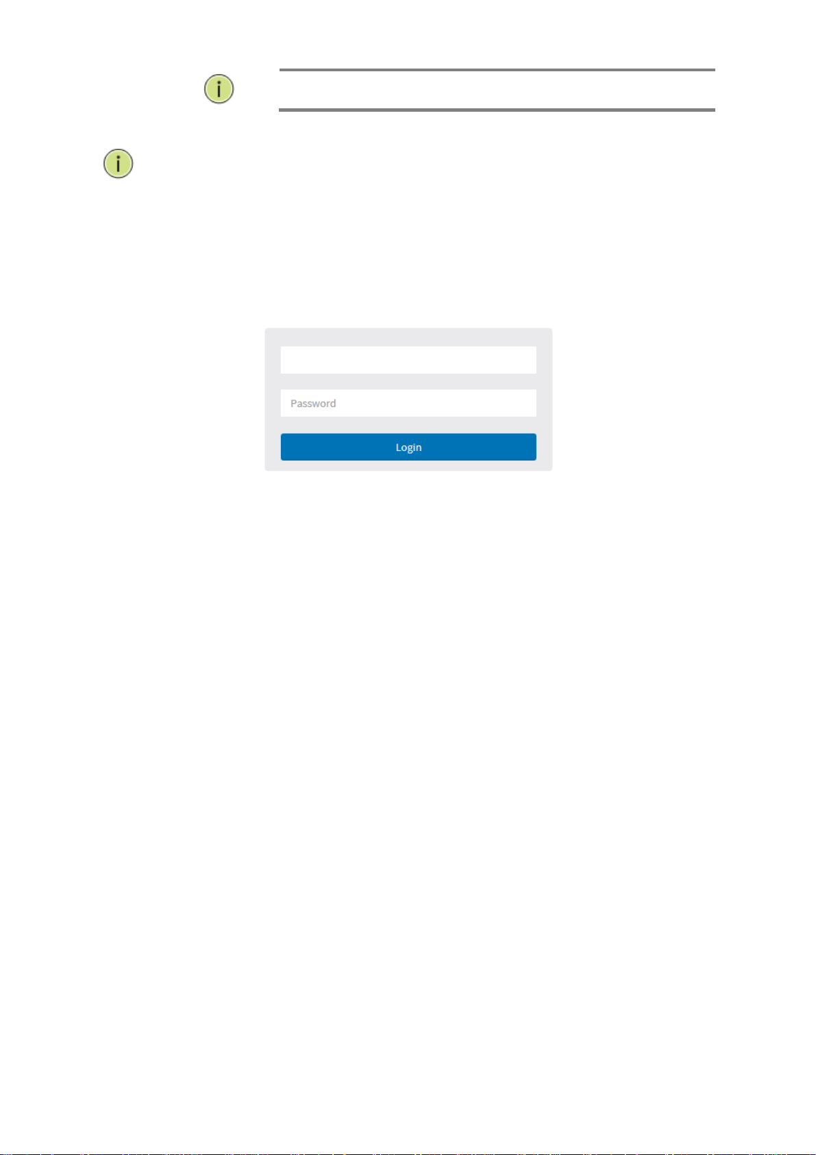
show the following screen and ask you inputting username and password in order to
login and access authentication.
The default username is “admin” and password is admin. For the first time to use,
please enter the default username and password, and then click the <Login> button.
The login process now is completed. In this login menu, you have to input the
complete username and password respectively, the AW-GEV-107A and -267A will not
give you a shortcut to username automatically. This looks inconvenient,
In the AW-GEV-107A and -267A, allowed two or more users using administrator’s
identity to manage this switch, which administrator to do the last setting, it will be an
available configuration to effect the system.
192.168.1.254
in the address row in a browser, it will
but safer.
NOTE:
When you login the Switch WEB/CLI to manager. You must first type the
Username of the admin. Password was blank, so when you type after the end
Username, please press enter. Management page to enter WEB/CLI.
When you login AW-GEV-107A and -267A series switch Web UI
management, you can use both ipv4 ipv6 login to manage
To optimize the display effect, we recommend you use Microsoft IE 6.0
above, Netscape V7.1 above or Firefox V1.00 above and have the resolution
1024x768. The switch supported neutral web browser interface
You can find the PoE switch using VIVOTEK’s IW2 utility. If network address conflicts occur, use this utility to
locate the PoE switch.
Ifyoudouble‐clickontheentryfoundonthe
IW2utility,anIEconsolewillbeopened.If
youpreferusingFirefoxorGoogleChrome,
youcanmanuallyentertheIPaddressin
yourbrowser’sURLfield.
User Manual rev. 1.0. Mar. 2017
2
2
Page 10
NOTE:
N
OTE:
The PoE switch and all cameras attached must be configured in the same subnet. Otherwise,
the Surveillance-related functions will not apply. You can let the PoE switch be a DHCP client
(listening to a DHCP server for IP assignment), or enable its onboard DHCP server.
Figure 1 The login page
The Switch default ip is DHCP client.
5
Publication date: Nov., 2016
Revision A1
Page 11
Chapter 2 System Configuration
This chapter describes the entire basic configuration tasks which includes the System Information and
any management of the Switch (e.g. Time, Account, IP, Syslog and NTP.)
2-1 System
You can identify the system by configuring the contact information, name, and location of the
switch.
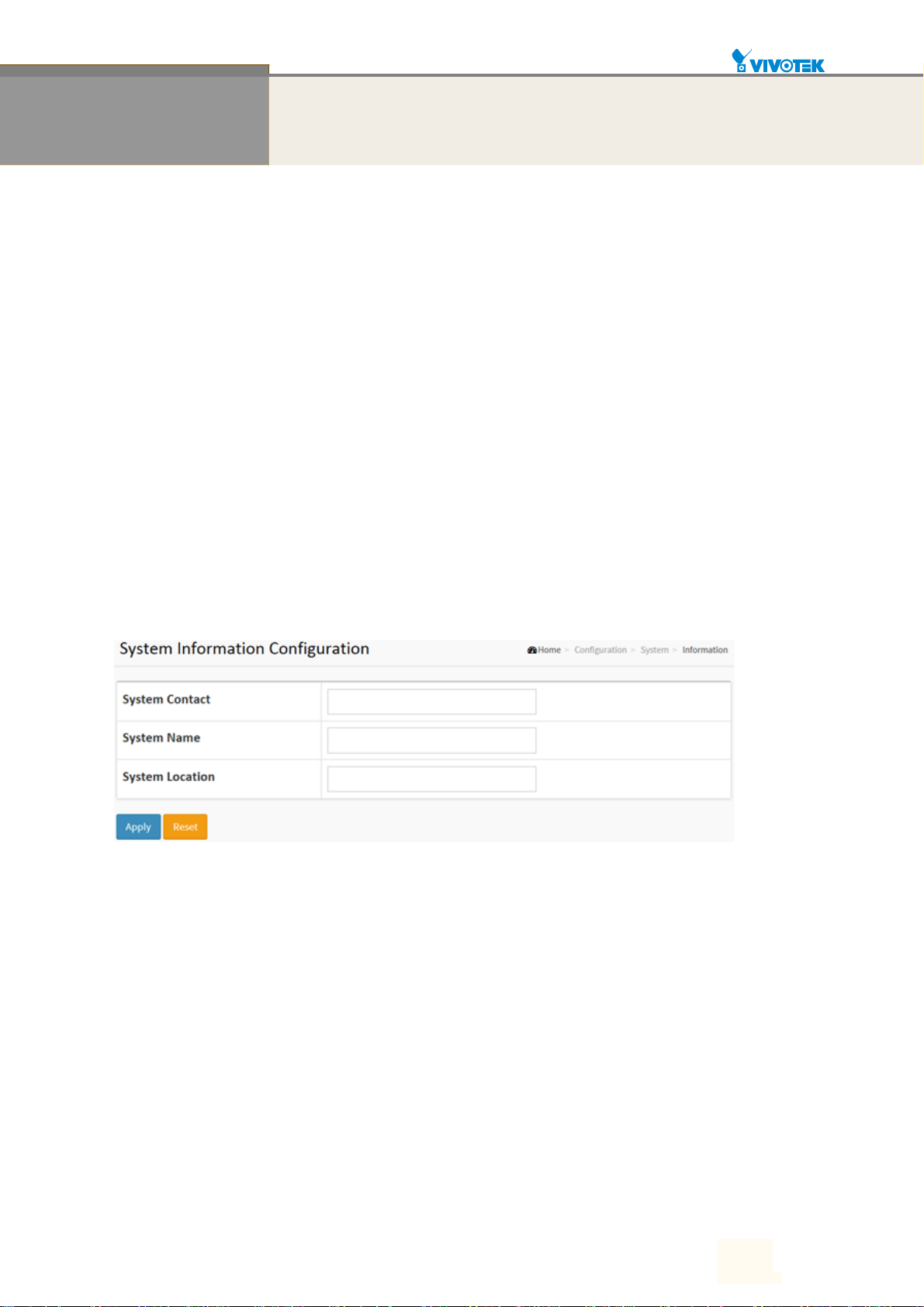
2-1.1 Information
The switch system’s contact information is provided here.
Web interface
To configure System Information in the web interface:
1. Click Configuration, System, and Information.
2. Write System Contact, System Name, System Location information in this page.
3. Click Apply
Figure 2-1.1: System Information
Parameter description:
System Contact:
The textual identification of the contact person for this managed node, together with
information on how to contact this person. The allowed string length is 0 to 128, and the
allowed content is the ASCII characters from 32 to 126.
System name:
An administratively assigned name for this managed node. By convention, this is the node's
fully-qualified domain name. A domain name is a text string drawn from the alphabet
(A-Za-z), digits (0-9), minus sign (-). No space characters are permitted as part of a name.
The first character must be an alpha character. And the first or last character must not be a
minus sign. The allowed string length is 0 to 128.
System Location:
The physical location of this node(e.g., telephone closet, 3rd floor). The allowed string
length is 0 to 128, and the allowed content is the ASCII characters from 32 to 126.
User Manual rev. 1.0. Mar. 2017
6
6
Page 12
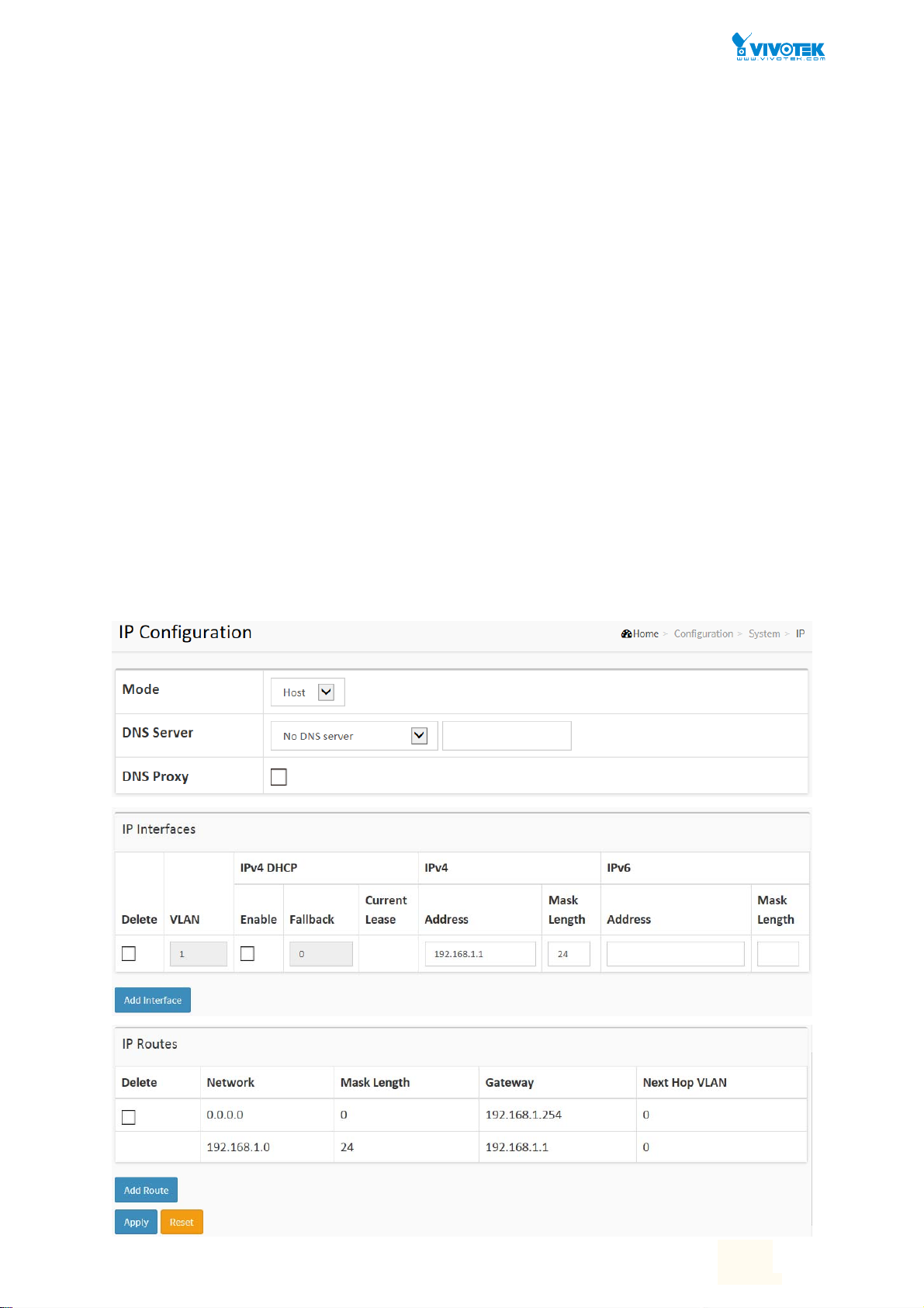
2-1.2 IP
The IPv4 address for the switch could be obtained via DHCP Server for VLAN 1. To manually
configure an address, you need to change the switch's default settings to values that are
compatible with your network. You may also need to establish a default gateway between the
switch and management stations that exist on another network segment.
Configure the switch-managed IP information on this page
Configure IP basic settings, control IP interfaces and IP routes.
The maximum number of interfaces supported is 8 and the maximum number of routes is 32.
Web Interface
To configure an IP address in the web interface:
1. Click Configuration, System, IP.
2. Click Add Interface then you can create new Interface on the switch.
3. Click Add Route then you can create new Route on the switch.
4. Click Apply.
Figure2-1.2: The IP configuration
User Manual rev. 1.0. Mar. 2017
7
7
Page 13

Parameter description:
IP Configuration
Mode:
Configure whether the IP stack should act as a Host or a Router. In Host mode, IP traffic
between interfaces will not be routed. In Router mode traffic is routed between all
interfaces.
DNS Server
This setting controls the DNS name resolution done by the switch. The following modes are
supported:
From any DHCP interfaces
The first DNS server offered from a DHCP lease to a DHCP-enabled interface will be
used.
No DNS server
No DNS server will be used.
Configured
Explicitly provide the IP address of the DNS Server in dotted decimal notation.
From this DHCP interface
Specify from which DHCP-enabled interface a provided DNS server should be
preferred.
DNS Proxy
When DNS proxy is enabled, system will relay DNS requests to the currently configured
DNS server, and reply as a DNS resolver to the client devices on the network.
IP Interfaces
Delete
Select this option to delete an existing IP interface.
VLAN
The VLAN associated with the IP interface. Only ports in this VLAN will be able to access the
IP interface. This field is only available for input when creating an new interface.
IPv4 DHCP Enabled
Enable the DHCP client by checking this box. If this option is enabled, the system will
configure the IPv4 address and mask of the interface using the DHCP protocol. The DHCP
client will announce the configured System Name as hostname to provide DNS lookup.
IPv4 DHCP Fallback Timeout
The number of seconds for trying to obtain a DHCP lease. After this period expires, a
configured IPv4 address will be used as IPv4 interface address. A value of zero disables the
fallback mechanism, such that DHCP will keep retrying until a valid lease is obtained. Legal
values are 0 to 4294967295 seconds.
IPv4 DHCP Current Lease
For DHCP interfaces with an active lease, this column show the current interface address, as
provided by the DHCP server.
IPv4 Address
The IPv4 address of the interface in dotted decimal notation.
If DHCP is enabled, this field is not used. The field may also be left blank if IPv4 operation
on the interface is not desired.
IPv4 Mask
User Manual rev. 1.0. Mar. 2017
8
8
Page 14

The IPv4 network mask, in number of bits (prefix length). Valid values are between 0 and 30
bits for a IPv4 address.
If DHCP is enabled, this field is not used. The field may also be left blank if IPv4 operation
on the interface is not desired.
IPv6 Address
The IPv6 address of the interface. A IPv6 address is in 128-bit records represented as eight
fields of up to four hexadecimal digits with a colon separating each field (:). For example,
fe80::215:c5ff:fe03:4dc7. The symbol:: is a special syntax that can be used as a shorthand
way of representing multiple 16-bit groups of contiguous zeros; but it can appear only once.
It can also represent a legally valid IPv4 address. For example, ::192.1.2.34.
The field may be left blank if IPv6 operation on the interface is not desired.
IPv6 Mask
The IPv6 network mask, in number of bits (prefix length). Valid values are between 1 and
128 bits for a IPv6 address.
The field may be left blank if IPv6 operation on the interface is not desired.
IP Routes
Delete
Select this option to delete an existing IP route.
Network
The destination IP network or host address of this route. Valid format is dotted decimal
notationor a valid IPv6 notation. A default route can use the value 0.0.0.0or IPv6 :: notation.
Mask Length
The destination IP network or host mask, in number of bits (prefix length). It defines how
much of a network address that must match, in order to qualify for this route. Valid values
are between 0 and 32 bits respectively 128 for IPv6 routes. Only a default route will have a
mask length of 0 (as it will match anything).
Gateway
The IP address of the IP gateway. Valid format is dotted decimal notationor a valid IPv6
notation. Gateway and Network must be of the same type.
Next Hop VLAN (Only for IPv6)
The VLAN ID (VID) of the specific IPv6 interface associated with the gateway.
The given VID ranges from 1 to 4094 and will be effective only when the corresponding IPv6
interface is valid.
If the IPv6 gateway address is link-local, it must specify the next hop VLAN for the gateway.
If the IPv6 gateway address is not link-local, system ignores the next hop VLAN for the
gateway.
Buttons
Add Interface:
Click to add a new IP interface. A maximum of 8 interfaces is supported.
Add Route:
Click to add a new IP route. A maximum of 32 routes is supported.
Apply:
Click to save changes.
Reset:
Click to undo any changes made locally and revert to previously saved values.
User Manual rev. 1.0. Mar. 2017
9
9
Page 15
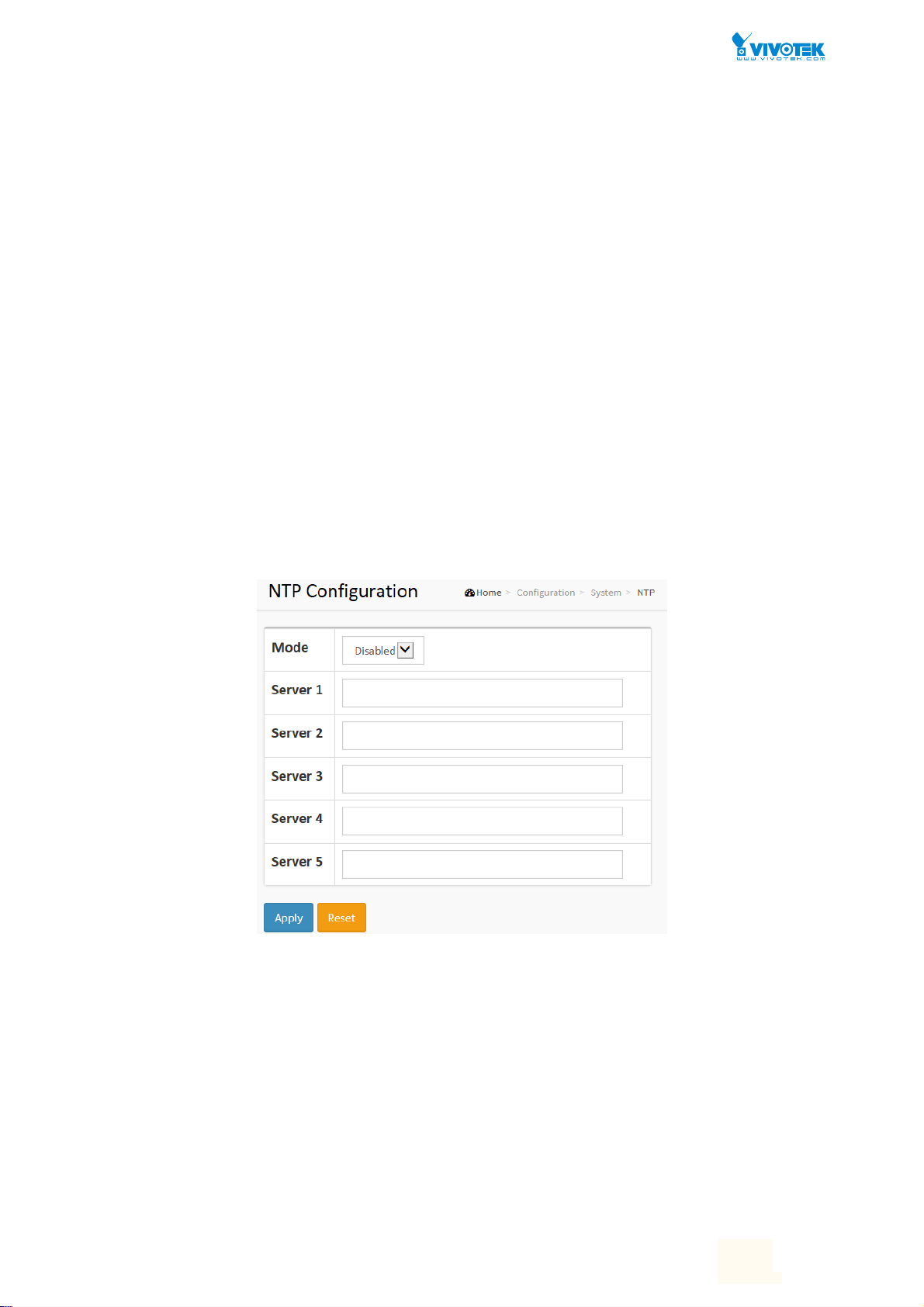
2-1.3 NTP
NTP is Network Time Protocol and is used to sync the network time based Greenwich Mean
Time (GMT). If use the NTP mode and select a built-in NTP time server or manually specify an
user-defined NTP server as well as Time Zone, the switch will sync the time in a short after
pressing <Apply> button. Though it synchronizes the time automatically, NTP does not update
the time periodically without user’s processing.
Time Zone is an offset time off GMT. You have to select the time zone first and then perform
time sync via NTP because the switch will combine this time zone offset and updated NTP time
to come out the local time, otherwise, you will not able to get the correct time. The switch
supports configurable time zone from –12 to +13 step 1 hour.
Default Time zone: +8 Hrs.
Web Interface
To configure NTP in the web interface:
1. Click Configuration, System, NTP.
2. Specify the Time parameter in manual parameters.
3. Click Apply.
Figure 2-1.3: The NTP configuration
Parameter description:
Mode :
Indicates the NTP mode operation. Possible modes are:
Enabled: Enable NTP client mode operation.
Disabled: Disable NTP client mode operation.
Server 1 to 5 :
Provide the NTP IPv4 or IPv6 address of this switch. IPv6 address is in 128-bit records
represented as eight fields of up to four hexadecimal digits with a colon separating each
field (:). For example, 'fe80::215:c5ff:fe03:4dc7'. The symbol '::' is a special syntax that can be
used as a shorthand way of representing multiple 16-bit groups of contiguous zeros; but it
can only appear once. It can also represent a legally valid IPv4 address. For example,
User Manual rev. 1.0. Mar. 2017
10
10
Page 16

'::192.1.2.34'.
User Manual rev. 1.0. Mar. 2017
11
11
Page 17
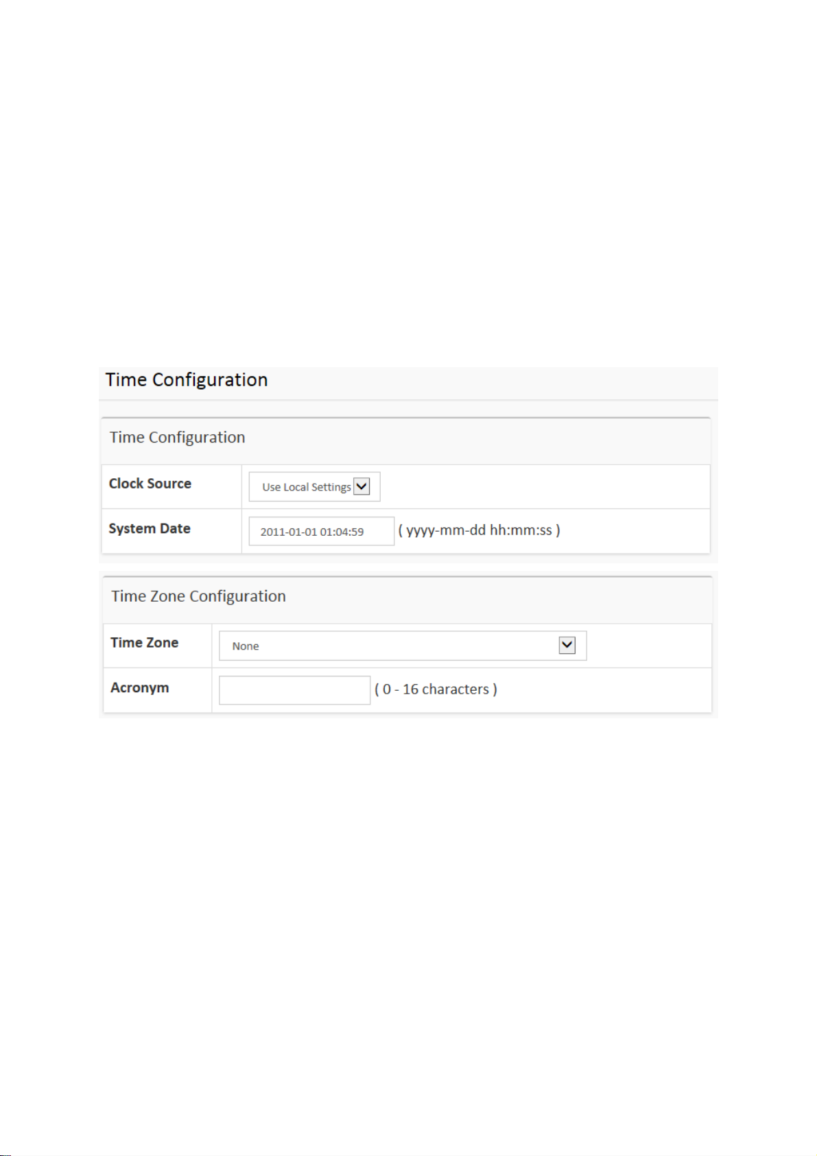
2-1.4 Time
The switch provides manual and automatic ways to set the system time via NTP. Manual setting
is simple and you just input “Year”, “Month”, “Day”, “Hour” and “Minute” within the valid value
range indicated in each item.
Web Interface
To configure Time in the web interface:
1. Click Configuration, System and Time
2. Specify the Time parameter.
3. Click Apply.
Figure 2-1.4: The time configuration
11
Publication date: Nov., 2016
Revision A1
Page 18
Parameter description:
Time Configuration
Clock Source:
There are two modes for configuring how the Clock Source from. Select "Use Local
Settings" : Clock Source from Local Time. Select "Use NTP Server" : Clock Source from NTP
Server.
System Date:
Show the current time of the system. The year of system date limits between 2011 and 2037.
Time Zone Configuration
Time Zone:
Lists various Time Zones worldwide. Select appropriate Time Zone from the drop down and
click Apply to set.
Acronym:
User can set the acronym of the time zone. This is a User configurable acronym to identify
the time zone. (Range: Up to 16 characters)
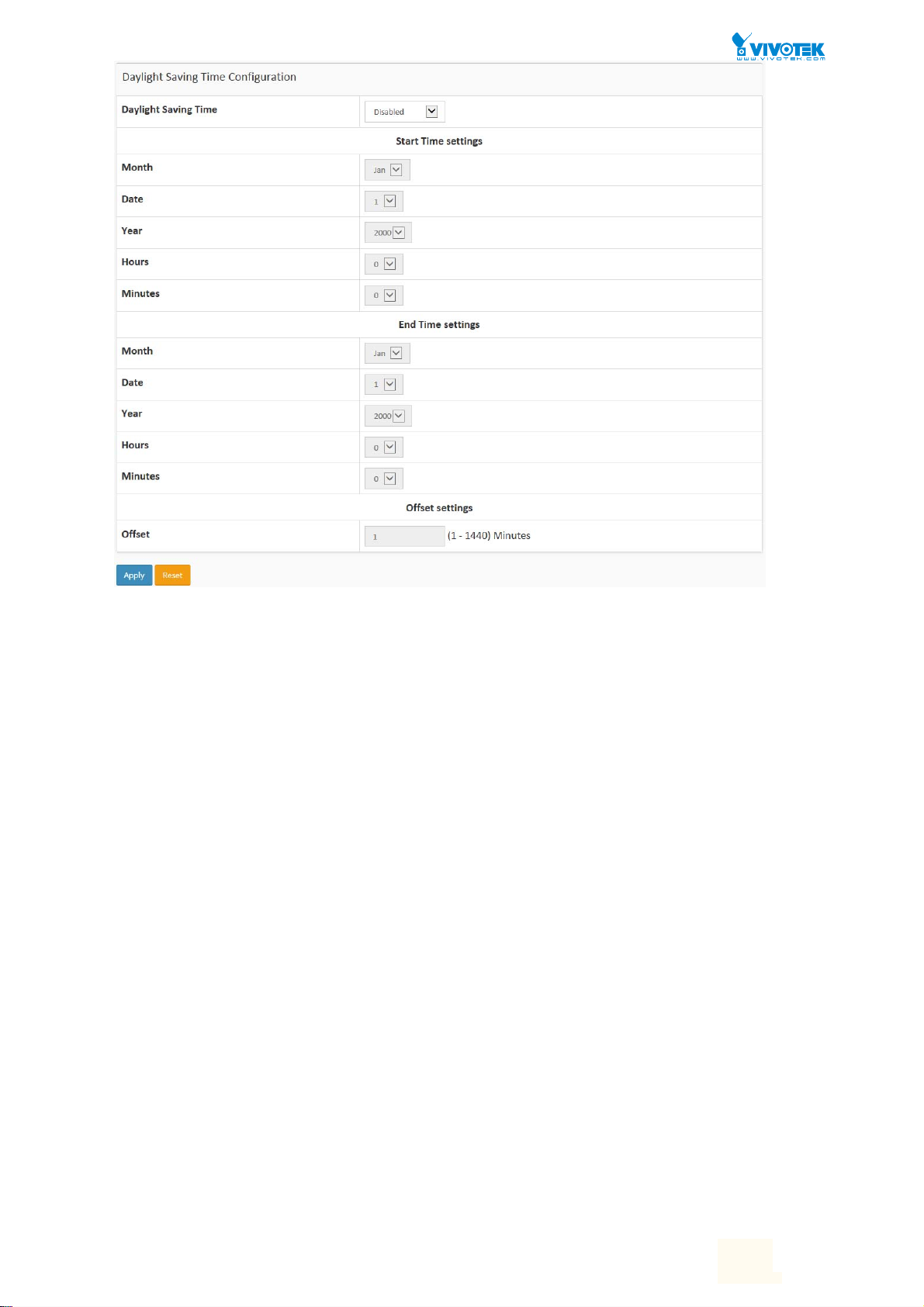
Daylight Saving Time Configuration
Daylight Saving Time:
This is used to set the clock forward or backward according to the configurations set below
for a defined Daylight Saving Time duration. Select 'Disable' to disable the Daylight Saving
Time configuration. Select 'Recurring' and configure the Daylight Saving Time duration to
repeat the configuration every year. Select 'Non-Recurring' and configure the Daylight
Saving Time duration for single time configuration. (Default: Disabled).
Recurring Configuration
User Manual rev. 1.0. Mar. 2017
12
12
Page 19

Start time settings:
Week - Select the starting week number.
Day - Select the starting day.
Month - Select the starting month.
Hours - Select the starting hour.
Minutes - Select the starting minute.
End time settings:
Week - Select the ending week number.
Day - Select the ending day.
Month - Select the ending month.
Hours - Select the ending hour.
Minutes - Select the ending minute.
Offset settings:
Offset - Enter the number of minutes to add during Daylight Saving Time. ( Range: 1 to
1440 )
Buttons
These buttons are displayed on the NTP page:
Apply – Click to save changes.
Reset - Click to undo any changes made locally and revert to previously saved values.
NOTE: The under “Start Time Settings” and “End Time Settings” was
displayed what you set on the “Start Time Settings” and “End Time
Settings” field information.
User Manual rev. 1.0. Mar. 2017
13
13
Page 20
2-1.5 Log
The log is a standard for logging program messages . It allows separation of the software that
generates messages from the system that stores them and the software that reports and
analyzes them. It can be used as well a generalized informational, analysis and debugging
messages. It is supported by a wide variety of devices and receivers across multiple platforms.
Web Interface
To configure log configuration in the web interface:
1. Click Configuration, System and log.
2. Specify the syslog parameters include IP Address of Syslog server and Port number.
3. Evoke the Syslog to enable it.
4. Click Apply.
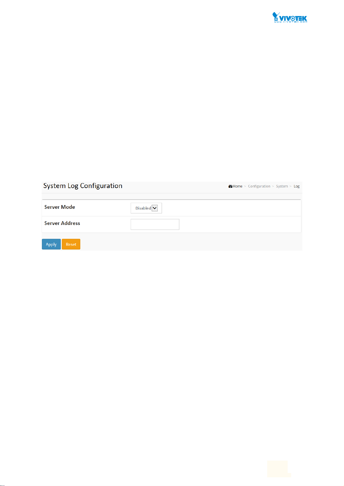
Figure2-1.5: The System Log configuration
Parameter description:
Server Mode :
Indicate the server mode operation. When the mode operation is enabled, the syslog
message will send out to syslog server. The syslog protocol is based on UDP communication
and received on UDP port 514 and the syslog server will not send acknowledgments back
sender since UDP is a connectionless protocol and it does not provide acknowledgments.
The syslog packet will always send out even if the syslog server does not exist. Possible
modes are:
Enabled: Enable server mode operation.
Disabled: Disable server mode operation.
Server Address :
Indicates the IPv4 hosts address of syslog server. If the switch provide DNS feature, it also
can be a host name.
Syslog Level :
Indicates what kind of message will send to syslog server. Possible modes are:
Info: Send information, warnings and errors.
Warning: Send warnings and errors.
Error: Send errors.
User Manual rev. 1.0. Mar. 2017
14
14
Page 21
2-2 Green Ethernet
EEE is a power saving option that reduces the power usage when there is low or no traffic
utilization.
EEE works by powering down circuits when there is no traffic. When a port gets data to be
transmitted all circuits are powered up. The time it takes to power up the circuits is named
wakeup time. The default wakeup time is 17 us for 1Gbit links and 30 us for other link speeds.
EEE devices must agree upon the value of the wakeup time in order to make sure that both the
receiving and transmitting device has all circuits powered up when traffic is transmitted. The
devices can exchange wakeup time information using the LLDP protocol.
EEE works for ports in auto-negotiation mode, where the port is negotiated to either 1G or 100
Mbit full duplex mode.
For ports that are not EEE-capable the corresponding EEE checkboxes are grayed out and thus
impossible to enable EEE for.
When a port is powered down for saving power, outgoing traffic is stored in a buffer until the
port is powered up again. Because there are some overhead in turning the port down and up,
more power can be saved if the traffic can be buffered up until a large burst of traffic can be
transmitted. Buffering traffic will give some latency in the traffic.
Web Interface
To configure a Port Power Saving Configuration in the web interface:
1. Click Configuration, Green Ethernet
2. Evoke to enable or disable the ActiPHY, PerfectReach, EEE and EEE Urgent Queues.
3. Click Apply.
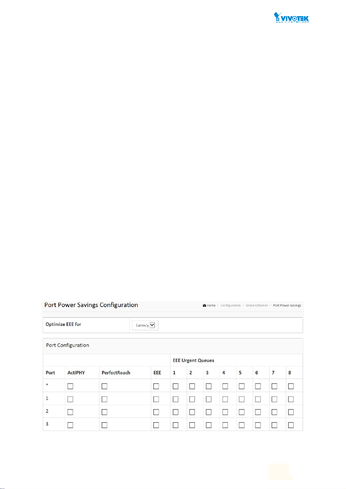
Figure 2-2.1: The Port Power Saving Configuration
User Manual rev. 1.0. Mar. 2017
15
15
Page 22

Parameter description:
Optimize EEE for
The switch can be set to optimize EEE for either best power saving or least traffic latency.
Port:
The switch port number of the logical port.
ActiPHY :
Link down power savings enabled.
ActiPHY works by lowering the power for a port when there is no link. The port is power up
for short moment in order to determine if cable is inserted.
PerfectReach :
Cable length power savings enabled.
PerfectReach works by determining the cable length and lowering the power for ports with
short cables.
EEE :
Controls whether EEE is enabled for this switch port.
For maximizing power savings, the circuit isn't started at once transmit data is ready for a
port, but is instead queued until a burst of data is ready to be transmitted. This will give
some traffic latency.
If desired it is possible to minimize the latency for specific frames, by mapping the frames to
a specific queue (done with QOS), and then mark the queue as an urgent queue. When an
urgent queue gets data to be transmitted, the circuits will be powered up at once and the
latency will be reduced to the wakeup time.
EEE Urgent Queues :
Queues set will activate transmission of frames as soon as data is available. Otherwise the
queue will postpone transmission until a burst of frames can be transmitted.
User Manual rev. 1.0. Mar. 2017
16
16
Page 23
2-3 Ports Configuration
The section describes to configure the Port detail parameters of the switch. Others you could
using the Port configure to enable or disable the Port of the switch. Monitor the ports content
or status in the function.
2-3.1 Ports
This page displays current port configurations. Ports can also be configured here.
Web Interface
To configure a Current Port Configuration in the web interface:
1. Click Configuration, Ports Configuration, and Ports
2. Specify the Speed Configured, Flow Control, Maximum Frame size, Excessive Collision
mode and Power Control.
3. Click Apply.
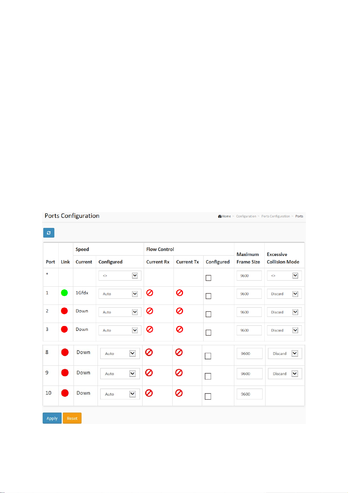
Figure 2-3.1: The Port Configuration
Parameter description:
Port :
This is the logical port number for this row.
Link :
Page 24

The current link state is displayed graphically. Green indicates the link is up and red that it is
down.
Current Link Speed :
Provides the current link speed of the port.
Configured Link Speed :
Selects any available link speed for the given switch port. Only speeds supported by the
specific port is shown. Possible speeds are:
Disabled - Disables the switch port operation.
Auto - Port auto negotiating speed with the link partner and selects the highest speed that
is compatible with the link partner.
10Mbps HDX - Forces the cu port in 10Mbps half duplex mode.
10Mbps FDX - Forces the cu port in 10Mbps full duplex mode.
100Mbps HDX - Forces the cu port in 100Mbps half duplex mode.
100Mbps FDX - Forces the cu port in 100Mbps full duplex mode.
1Gbps FDX - Forces the port in 1Gbps full duplex
2.5Gbps FDX - Forces the Serdes port in 2.5Gbps full duplex mode.
SFP_Auto_AMS - Automatically determines the speed of the SFP. Note: There is no
standardized way to do SFP auto detect, so here it is done by reading the SFP rom. Due to
the missing standardized way of doing SFP auto detect some SFPs might not be detectable.
The port is set in AMS mode. Cu port is set in Auto mode.
100-FX - SFP port in 100-FX speed. Cu port disabled.
100-FX_AMS - Port in AMS mode. SFP port in 100-FX speed. Cu port in Auto mode.
1000-X - SFP port in 1000-X speed. Cu port disabled.
1000-X_AMS - Port in AMS mode. SFP port in 1000-X speed. Cu port in Auto mode. Ports in
AMS mode with 1000-X speed has Cu port preferred. Ports in AMS mode with 100-FX speed
has fiber port preferred.
Flow Control :
When Auto Speed is selected on a port, this section indicates the flow control capability that
is advertised to the link partner. When a fixed-speed setting is selected, that is what is used.
The Current Rx column indicates whether pause frames on the port are obeyed, and the
Current Tx column indicates whether pause frames on the port are transmitted. The Rx and
Tx settings are determined by the result of the last Auto-Negotiation.
Check the configured column to use flow control. This setting is related to the setting for
Configured Link Speed.
Maximum Frame Size :
Enter the maximum frame size allowed for the switch port, including FCS.
Excessive Collision Mode :
Configure port transmit collision behavior.
Discard: Discard frame after 16 collisions (default).
Restart: Restart backoff algorithm after 16 collisions.
User Manual rev. 1.0. Mar. 2017
19
19
Page 25
2-3.2 Ports Description
The section describes to configure the Port’s alias or any descriptions for the Port Identity. It
provides user to write down an alphanumeric string describing the full name and version
identification for the system’s hardware type, software version, and networking application
Web Interface
To configure a Port Description in the web interface:
1. Click Configuration, Port, then Port Description
2. Specify the detail Port alias or description an alphanumeric string describing the full name
and version identification for the system’s hardware type, software version, and networking
application.
3. Click Apply.
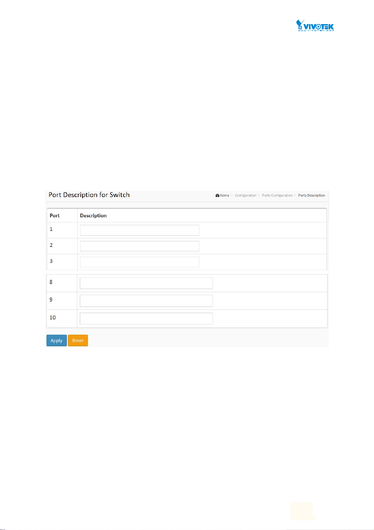
Figure 2-3.2: The Port Configuration
Parameter description:
Port :
This is the logical port number for this row.
Description :
Enter up to 47 characters to be descriptive name for identifies this port.
Buttons
Apply – Click to save changes.
Reset- Click to undo any changes made locally and revert to previously saved values.
User Manual rev. 1.0. Mar. 2017
20
20
Page 26
2-4DHCP
The section describes to configure the DHCP Snooping parameters of the switch. The DHCP
Snooping can prevent attackers from adding their own DHCP servers to the network.
2-4.1 Server
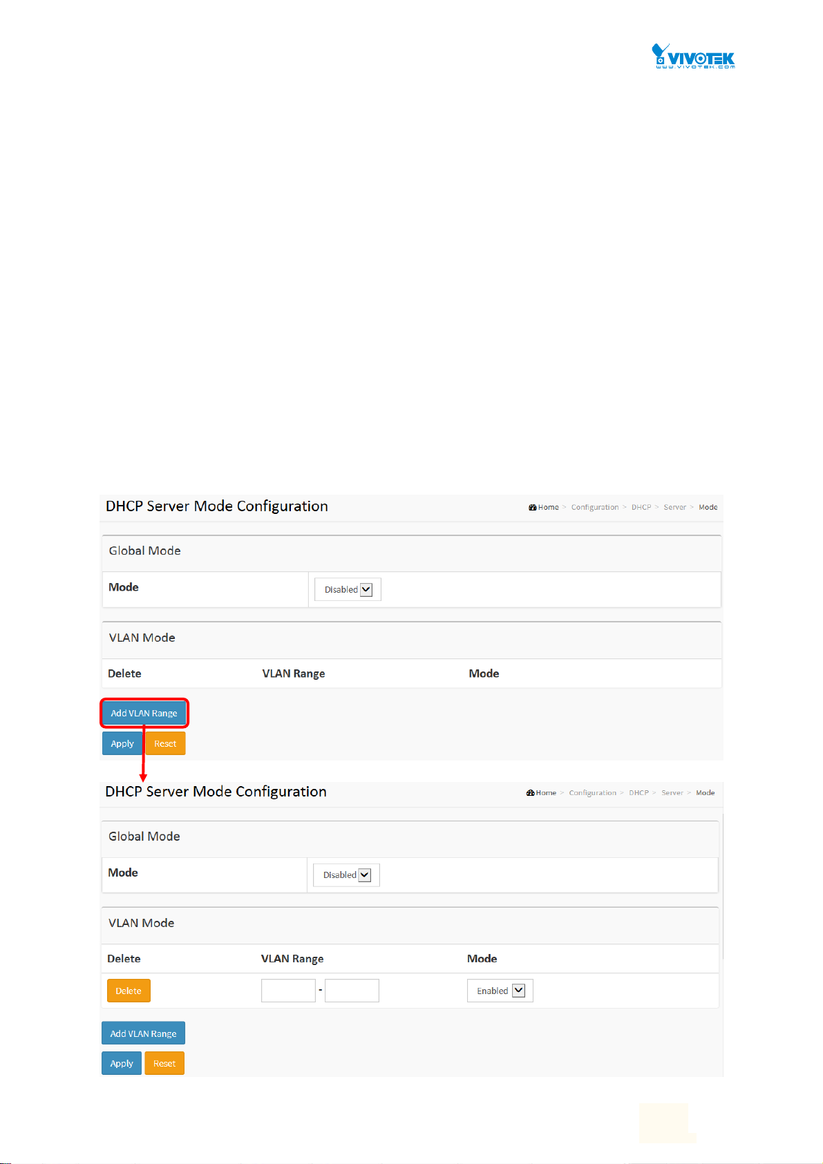
2-4.1.1 Mode
This page configures global mode and VLAN mode to enable/disable DHCP
server per system and per VLAN.
Web Interface
To configure DHCP server mode in the web interface:
1. Click Configuration, DHCP, Server, Mode
2. Select “Enabled” in the Global Mode of DHCP Server Mode Configuration.
3. Add Vlan range.
4. Click Apply.
Figure 2-4.1.1: The DHCP server Mode
User Manual rev. 1.0. Mar. 2017
21
21
Page 27

Parameter description:
Mode :
Configure the operation mode per system. Possible modes are:
Enabled: Enable DHCP server per system.
Disabled: Disable DHCP server pre system.
VLAN Range :
Indicate the VLAN range in which DHCP server is enabled or disabled. The first VLAN ID must be
smaller than or equal to the second VLAN ID. BUT, if the VLAN range contains only 1 VLAN ID, then
you can just input it into either one of the first and second VLAN ID or both.
On the other hand, if you want to disable existed VLAN range, then you can follow the steps.
1. press “ADD VLAN Range” to add a new VLAN range.
2. input the VLAN range that you want to disable.
3. choose Mode to be Disabled.
4. press Apply to apply the change.
Then, you will see the disabled VLAN range is removed from the DHCP Server mode configuration
page.
Mode :
Indicate the the operation mode per VLAN. Possible modes are:
Enabled: Enable DHCP server per VLAN.
Disabled: Disable DHCP server pre VLAN.
Buttons
Add VLAN Range - Click to add a new VLAN range.
Apply – Click to save changes.
Reset - Click to undo any changes made locally and revert to previously saved values.
User Manual rev. 1.0. Mar. 2017
22
22
Page 28
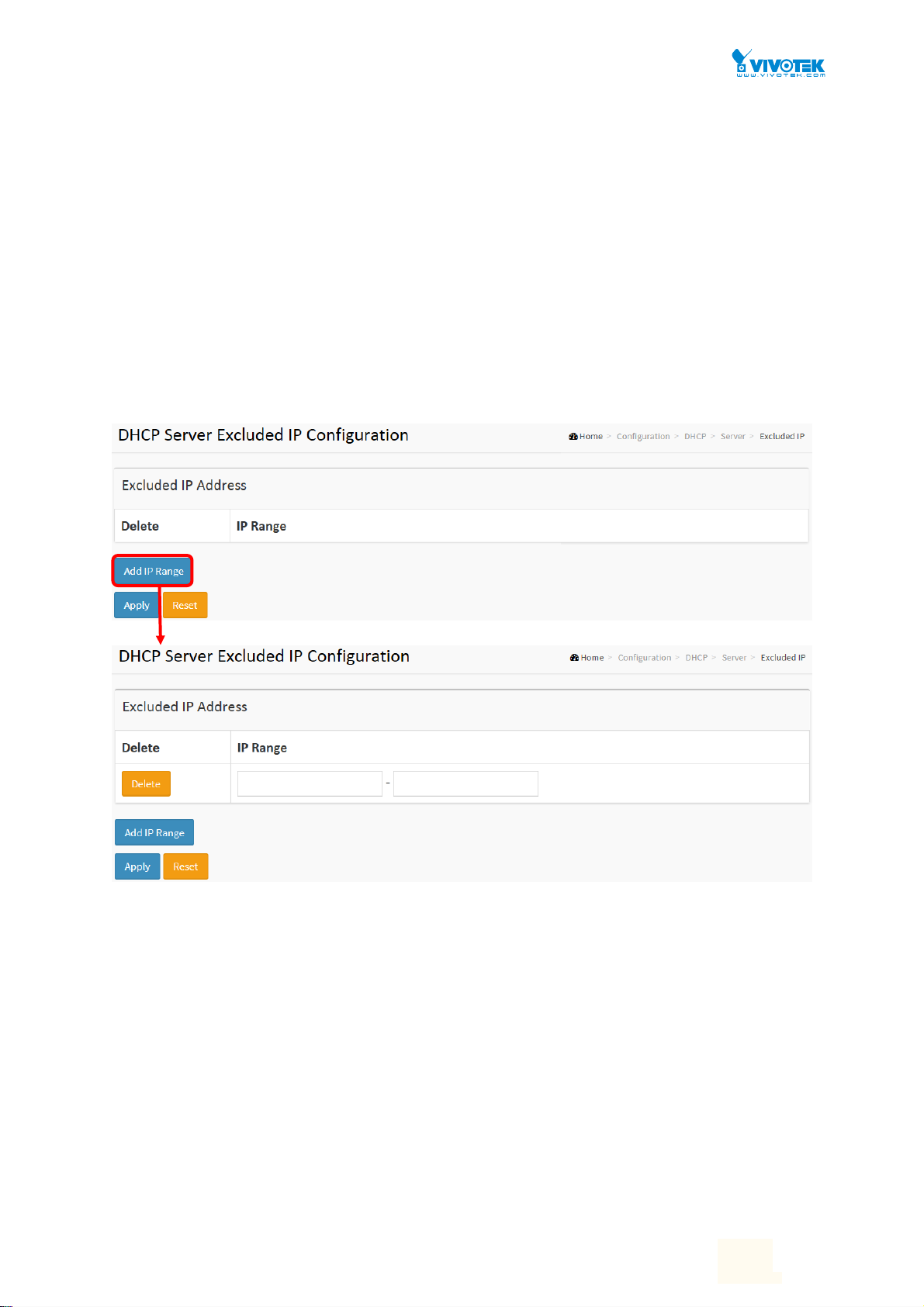
2-4.1.2 Excluded IP
This page configures excluded IP addresses. DHCP server will not allocate
these excluded IP addresses to DHCP client.
Web Interface
To configure DHCP server excluded IP in the web interface:
1. Click Configuration, DHCP, Server, Excluded IP
2. Click Add IP Range then you can create new IP Range on the switch.
3. Click Apply.
Figure 2-4.1.2: The DHCP server excluded IP
Parameter description:
IP Range :
Define the IP range to be excluded IP addresses. The first excluded IP must be smaller than or equal to
the second excluded IP. BUT, if the IP range contains only 1 excluded IP, then you can just input it to
either one of the first and second excluded IP or both.
Buttons
Add IP Range - Click to add a new excluded IP range.
Apply – Click to save changes.
Reset - Click to undo any changes made locally and revert to previously saved values.
User Manual rev. 1.0. Mar. 2017
23
23
Page 29
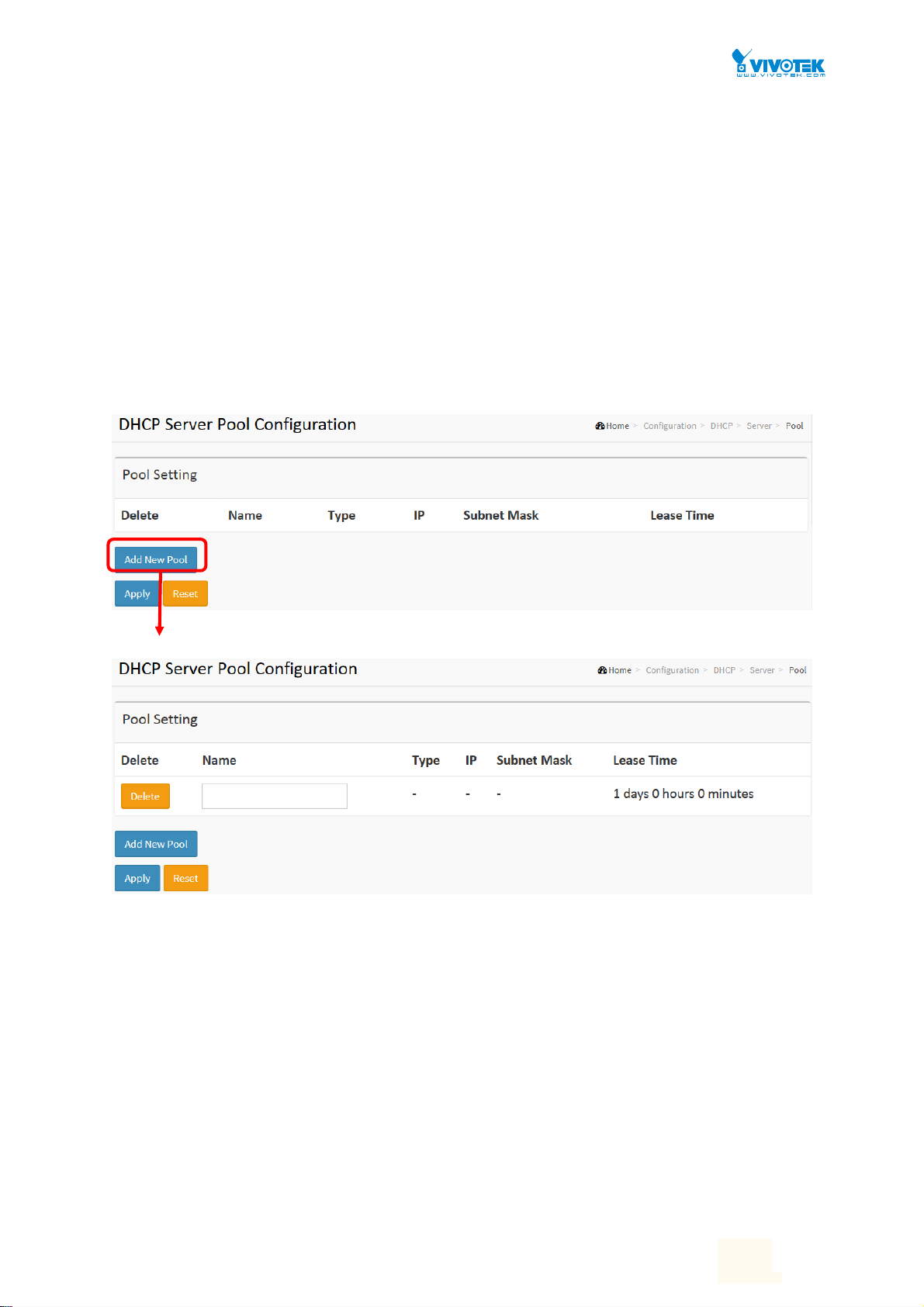
2-4.1.3 Pool
This page manages DHCP pools. According to the DHCP pool, DHCP server will
allocate IP address and deliver configuration parameters to DHCP client.
Web Interface
To configure DHCP server pool in the web interface:
1. Click Configuration, DHCP, Server, Pool
2. Click Add New Pool then you can create new Pool on the switch.
3. Click Apply.
Figure 2-4.1.3: The DHCP server pool
Parameter description:
Pool Setting
Add or delete pools.
Adding a pool and giving a name is to create a new pool with "default" configuration. If you
want to configure all settings including type, IP subnet mask and lease time, you can click
the pool name to go into the configuration page.
Name :
Configure the pool name that accepts all printable characters, except white space. If you want to
configure the detail settings, you can click the pool name to go into the configuration page.
Type :
Display which type of the pool is.
User Manual rev. 1.0. Mar. 2017
24
24
Page 30

Network: the pool defines a pool of IP addresses to service more than one DHCP client.
Host: the pool services for a specific DHCP client identified by client identifier or hardware address.
If "-" is displayed, it means not defined.
IP :
Display network number of the DHCP address pool.
If "-" is displayed, it means not defined.
Subnet Mask :
Display subnet mask of the DHCP address pool.
If "-" is displayed, it means not defined.
Lease Time :
Display lease time of the pool.
Buttons
Add New Pool - Click to add a new DHCP pool.
Apply – Click to save changes.
Reset - Click to undo any changes made locally and revert to previously saved values.
User Manual rev. 1.0. Mar. 2017
25
25
Page 31

2-4.2 Snooping
DHCP Snooping is used to block intruder on the untrusted ports of the switch
device when it tries to intervene by injecting a bogus DHCP reply packet to a
legitimate conversation between the DHCP client and server.
The section describes to configure the DHCP Snooping parameters of the
switch. The DHCP Snooping can prevent attackers from adding their own
DHCP servers to the network.
Web Interface
To configure DHCP snooping in the web interface:
1. Click Configuration, DHCP, Snooping
2. Select “Enabled” in the Mode of DHCP Snooping Configuration.
3. Select “Trusted” of the specific port in the Mode of Port Mode Configuration.
4. Click Apply.
Figure 2-4.2: The DHCP Snooping Configuration
Parameter description:
Snooping Mode :
Indicates the DHCP snooping mode operation. Possible modes are:
Enabled: Enable DHCP snooping mode operation. When DHCP snooping mode operation is
enabled, the DHCP request messages will be forwarded to trusted ports and only allow reply
packets from trusted ports.
Disabled: Disable DHCP snooping mode operation.
Port Mode Configuration
User Manual rev. 1.0. Mar. 2017
26
26
Page 32

Indicates the DHCP snooping port mode. Possible port modes are:
Trusted: Configures the port as trusted source of the DHCP messages.
Untrusted: Configures the port as untrusted source of the DHCP messages.
Buttons
Apply – Click to save changes.
Reset - Click to undo any changes made locally and revert to previously saved values.
User Manual rev. 1.0. Mar. 2017
27
27
Page 33

2-5 Security
This section shows you to configure the Port Security settings of the Switch. You can use the
Port Security feature to restrict input to an interface by limiting and identifying MAC addresses.
2-5.1 Switch
2-5.1.1 Users
This page provides an overview of the current users. Currently the only way to login as another
user on the web server is to close and reopen the browser
Web Interface
To configure User in the web interface:
1. Click Configuration, Security, Switch, Users.
2. Click Add new user
3. Specify the User Name parameter.
4. Click Apply.
Figure 2-5.1.1: The Users configuration
Parameter description:
User Name :
The name identifying the user. This is also a link to Add/Edit User.
Password
User Manual rev. 1.0. Mar. 2017
28
28
Page 34

To type the password. The allowed string length is 0 to 255, and the allowed content is the
ASCII characters from 32 to 126.
Password (again)
To type the password again. You must type the same password again in the field.
Privilege Level :
The privilege level of the user. The allowed range is 1 to 15. If the privilege level value is 15, it
can access all groups, i.e. that is granted the fully control of the device. But others value
need to refer to each group privilege level. User's privilege should be same or greater than
the group privilege level to have the access of that group. By default setting, most groups
privilege level 5 has the read-only access and privilege level 10 has the read-write access.
And the system maintenance (software upload, factory defaults and etc.) need user privilege
level 15. Generally, the privilege level 15 can be used for an administrator account, privilege
level 10 for a standard user account and privilege level 5 for a guest account.
Buttons
Apply – Click to save changes.
Reset - Click to undo any changes made locally and revert to previously saved values.
Cancel - Click to undo any changes made locally and return to the Users.
Delete User - Delete the current user. This button is not available for new configurations
(Add new user)
User Manual rev. 1.0. Mar. 2017
29
29
Page 35

2-5.1.2 Privilege Level
This page provides an overview of the privilege levels. The switch provides user set Account,
Aggregation, Diagnostics, EEE, GARP, GVRP,IP, IPMC Snooping LACP LLDP LLDP MED MAC
Table MRP MVR MVRP Maintenance Mirroring POE Ports Private VLANs QoS SMTP SNMP
Security Spanning Tree System Trap Event VCL VLANs Voice VLAN Privilege Levels from 1 to
15 .
Web Interface
To configure Privilege Level in the web interface:
1. Click SYSTEM, Account, Privilege Level.
2. Specify the Privilege parameter.
3. Click Apply.
Figure2-5.1.2: The Privilege Level configuration
Parameter description:
Group Name
The name identifying the privilege group. In most cases, a privilege level group consists of a
single module (e.g. LACP, RSTP or QoS), but a few of them contains more than one. The
following description defines these privilege level groups in details:
System: Contact, Name, Location, Timezone, Daylight Saving Time, Log.
Security: Authentication, System Access Management, Port (contains Dot1x port, MAC
User Manual rev. 1.0. Mar. 2017
30
30
Page 36

based and the MAC Address Limit), ACL, HTTPS, SSH, ARP Inspection, IP source guard.
IP: Everything except 'ping'.
Port: Everything except 'VeriPHY'.
Diagnostics: 'ping' and 'VeriPHY'.
Maintenance: CLI- System Reboot, System Restore Default, System Password, Configuration
Save, Configuration Load and Firmware Load. Web- Users, Privilege Levels and everything in
Maintenance.
Debug: Only present in CLI.
Privilege Levels
Every group has an authorization Privilege level for the following sub groups: configuration
read-only, configuration/execute read-write, status/statistics read-only, status/statistics
read-write (e.g. for clearing of statistics). User Privilege should be same or greater than the
authorization Privilege level to have the access to that group.
Buttons
Apply – Click to save changes.
Reset - Click to undo any changes made locally and revert to previously saved values.
User Manual rev. 1.0. Mar. 2017
31
31
Page 37

2-5.1.3 Authentication Method
This page shows how to configure a user with authenticated when he logs into the switch via
one of the management client interfaces.
Web Interface
To configure an Authentication Method Configuration in the web interface:
1. Specify the Client ( ssh, web) which you want to monitor.
2. Specify the Authentication Method (none,local, radius, tacacs+)
3. Checked Fallback.
4. Click Apply.
Figure 2-5.1.3: The Authentication Method Configuration
Parameter description:
Client :
The management client for which the configuration below applies.
Authentication Method :
Authentication Method can be set to one of the following values:
none : authentication is disabled and login is not possible.
local : use the local user database on the switch for authentication.
radius : use a remote RADIUS server for authentication.
tacacs+ : use a remote TACACS+ server for authentication.
Methods that involves remote servers are timed out if the remote servers are offline. In this
case the next method is tried. Each method is tried from left to right and continues until a
method either approves or rejects a user. If a remote server is used for primary
authentication it is recommended to configure secondary authentication as 'local'. This will
enable the management client to login via the local user database if none of the configured
authentication servers are alive.
Buttons:
Apply – Click to save changes.
Reset- Click to undo any changes made locally and revert to previously saved values.
User Manual rev. 1.0. Mar. 2017
32
32
Page 38

2-5.1.4 HTTPs
This section shows you how to use HTTPS to securely access the Switch. HTTPS is a secure
communication protocol that combines authentication and data encryption to provide secure
encrypted communication via the browser.
Web Interface
To configure a HTTPS Configuration in the web interface:
1. Select “Enabled” in the Mode of
2. Select “Enabled” in the Automatic Redirect of
3. Click Apply.
Figure 2-5.1.4: The HTTPS Configuration
HTTPS Configuration.
HTTPS Configuration.
Parameter description:
Mode :
Indicates the HTTPS mode operation. Possible modes are:
Enabled: Enable HTTPS mode operation.
Disabled: Disable HTTPS mode operation.
Automatic Redirect :
Indicates the HTTPS redirect mode operation. Automatically redirect web browser to HTTPS
when HTTPS mode is enabled. Possible modes are:
Enabled: Enable HTTPS redirect mode operation.
Disabled: Disable HTTPS redirect mode operation.
User Manual rev. 1.0. Mar. 2017
33
33
Page 39

2-5.1.5 SNMP
Any Network Management System (NMS) running the Simple Network Management Protocol
(SNMP) can manage the Managed devices equipped with SNMP agent, provided that the
Management Information Base (MIB) is installed correctly on the managed devices. The SNMP
is a protocol that is used to govern the transfer of information between SNMP manager and
agent and traverses the Object Identity (OID) of the management Information Base (MIB),
described in the form of SMI syntax. SNMP agent is running on the switch to response the
request issued by SNMP manager.
Basically, it is passive except issuing the trap information. The switch supports a switch to turn
on or off the SNMP agent. If you set the field SNMP “Enable”, SNMP agent will be started up.
All supported MIB OIDs, including RMON MIB, can be accessed via SNMP manager. If the field
SNMP is set “Disable”, SNMP agent will be de-activated, the related Community Name, Trap
Host IP Address, Trap and all MIB counters will be ignored.
2-5.1.5.1 System
This section describes how to configure SNMP System on the switch. This function is used to
configure SNMP settings, community name, trap host and public traps as well as the throttle
of SNMP. A SNMP manager must pass the authentication by identifying both community
names, then it can access the MIB information of the target device. So, both parties must have
the same community name. Once completing the setting, click <Apply> button, the setting
takes effect.
Web Interface
To display the configure SNMP System in the web interface:
1. Click SNMP, System.
2. Evoke SNMP State to enable or disable the SNMP function.
3. Specify the Engine ID.
4. Click Apply.
Figure2-5.1.5.1: The SNMP System Configuration
Parameter description:
Mode :
Indicates the SNMP mode operation. Possible modes are:
User Manual rev. 1.0. Mar. 2017
34
34
Page 40

Enabled:
Disabled: Disable SNMP mode operation.
Ver s ion
Indicates the SNMP supported version. Possible versions are:
SNMP v1: Set SNMP supported version 1.
SNMP v2c: Set SNMP supported version 2c.
SNMP v3: Set SNMP supported version 3.
Read Community
Indicates the community read access string to permit access to SNMP agent. The allowed
string length is 0 to 255, and the allowed content is the ASCII characters from 33 to 126.
The field is applicable only when SNMP version is SNMPv1 or SNMPv2c. If SNMP version is
SNMPv3, the community string will be associated with SNMPv3 communities table. It
provides more flexibility to configure security name than a SNMPv1 or SNMPv2c community
string. In addition to community string, a particular range of source addresses can be used
to restrict source subnet.
Write Community
Enable SNMP mode operation.
Indicates the community write access string to permit access to SNMP agent. The allowed
string length is 0 to 255, and the allowed content is the ASCII characters from 33 to 126.
The field is applicable only when SNMP version is SNMPv1 or SNMPv2c. If SNMP version is
SNMPv3, the community string will be associated with SNMPv3 communities table. It
provides more flexibility to configure security name than a SNMPv1 or SNMPv2c community
string. In addition to community string, a particular range of source addresses can be used
to restrict source subnet.
Engine ID
Indicates the SNMPv3 engine ID. The string must contain an even number(in hexadecimal
format) with number of digits between 10 and 64, but all-zeros and all-'F's are not allowed.
Change of the Engine ID will clear all original local users.
User Manual rev. 1.0. Mar. 2017
35
35
Page 41

2-5.1.5.2 Trap
Configure SNMP trap on this page.
Global Settings
Configure SNMP trap on this page.
Web Interface
To display the configure SNMP Trap Configuration in the web interface:
1. Click Configuration, Switch, SNMP, Trap.
2. Click Add New Entry then you can create new SNMP Trap on the switch.
3. Click Apply.
Figure2-5.1.5.2: The SNMP Trap Configuration
Trap Mode
Indicates the trap mode operation. Possible modes are:
Enabled: Enable SNMP trap mode operation.
User Manual rev. 1.0. Mar. 2017
36
36
Page 42

Disabled: Disable SNMP trap mode operation.
Trap Destination Configurations
Configure trap destinations on this page.
Name
Indicates the trap Configuration's name. Indicates the trap destination's name.
Enable
Indicates the trap destination mode operation. Possible modes are:
Enabled: Enable SNMP trap mode operation.
Disabled: Disable SNMP trap mode operation.
Ver s ion
Indicates the SNMP trap supported version. Possible versions are:
SNMPv1: Set SNMP trap supported version 1.
SNMPv2c: Set SNMP trap supported version 2c.
SNMPv3: Set SNMP trap supported version 3.
Trap Community
Indicates the community access string when sending SNMP trap packet. The allowed string
length is 0 to 255, and the allowed content is ASCII characters from 33 to 126.
Destination Address
Indicates the SNMP trap destination address. It allow a valid IP address in dotted decimal
notation ('x.y.z.w').
And it also allow a valid hostname. A valid hostname is a string drawn from the alphabet
(A-Za-z), digits (0-9), dot (.), dash (-). Spaces are not allowed, the first character must be an
alpha character, and the first and last characters must not be a dot or a dash.
Indicates the SNMP trap destination IPv6 address. IPv6 address is in 128-bit records
represented as eight fields of up to four hexadecimal digits with a colon separating each field
(:). For example, 'fe80::215:c5ff:fe03:4dc7'. The symbol '::' is a special syntax that can be used as
a shorthand way of representing multiple 16-bit groups of contiguous zeros; but it can appear
only once. It can also represent a legally valid IPv4 address. For example, '::192.1.2.34'.
Destination port
Indicates the SNMP trap destination port. SNMP Agent will send SNMP message via this port,
the port range is 1~65535.
Trap Inform Mode
Indicates the SNMP trap inform mode operation. Possible modes are:
Enabled: Enable SNMP trap inform mode operation.
Disabled: Disable SNMP trap inform mode operation.
Trap Inform Timeout (seconds)
Indicates the SNMP trap inform timeout. The allowed range is 0 to 2147.
Trap Inform Retry Times
Indicates the SNMP trap inform retry times. The allowed range is 0 to 255.
Trap Probe Security Engine ID
Indicates the SNMP trap probe security engine ID mode of operation. Possible values are:
Enabled: Enable SNMP trap probe security engine ID mode of operation.
Disabled: Disable SNMP trap probe security engine ID mode of operation.
Trap Security Engine ID
User Manual rev. 1.0. Mar. 2017
37
37
Page 43

Indicates the SNMP trap security engine ID. SNMPv3 sends traps and informs using USM for
authentication and privacy. A unique engine ID for these traps and informs is needed. When
"Trap Probe Security Engine ID" is enabled, the ID will be probed automatically. Otherwise, the
ID specified in this field is used. The string must contain an even number(in hexadecimal
format) with number of digits between 10 and 64, but all-zeros and all-'F's are not allowed.
Trap Security Name
Indicates the SNMP trap security name. SNMPv3 traps and informs using USM for
authentication and privacy. A unique security name is needed when traps and informs are
enabled.
User Manual rev. 1.0. Mar. 2017
38
38
Page 44

2-5.1.5.3 Communities
The function is used to configure SNMPv3 communities. The Community and UserName is
unique. To create a new community account, please check <Add new community> button,
and enter the account information then check <Save>. Max Group Number: 4.
Web Interface
To display the configure SNMP Communities in the web interface:
1. Click SNMP, Communities.
2. Click Add new community.
3. Specify the SNMP communities parameters.
4. Click Apply.
5. If you want to modify or clear the setting then click Reset.
Figure2-5.1.5.3: The SNMPv1/v2 Communities Security Configuration
Parameter description:
Delete
Check to delete the entry. It will be deleted during the next save.
Community
Indicates the community access string to permit access to SNMPv3 agent. The allowed
string length is 1 to 32, and the allowed content is ASCII characters from 33 to 126. The
community string will be treated as security name and map a SNMPv1 or SNMPv2c
community string.
Source IP
Indicates the SNMP access source address. A particular range of source addresses can be
used to restrict source subnet when combined with source mask.
Source Mask
Indicates the SNMP access source address mask.
User Manual rev. 1.0. Mar. 2017
39
39
Page 45

2-5.1.5.4 Users
The function is used to configure SNMPv3 user. The Entry index key is UserName. To create a
new UserName account, please check <Add new user> button, and enter the user
information then check <Save>. Max Group Number : 10.
Web Interface
To display the configure SNMP Users in the web interface:
1. Click SNMP, Users.
2. Specify the Privilege parameter.
3. Click Apply.
Figure 2-5.1.5.4: The SNMP Users Configuration
Parameter description:
Delete
Check to delete the entry. It will be deleted during the next save.
Engine ID
An octet string identifying the engine ID that this entry should belong to. The string must
contain an even number (in hexadecimal format) with number of digits between 10 and 64,
but all-zeros and all-'F's are not allowed. The SNMPv3 architecture uses the User-based
Security Model (USM) for message security and the View-based Access Control Model
(VACM) for access control. For the USM entry, the usmUserEngineID and usmUserName are
the entry's keys. In a simple agent, usmUserEngineID is always that agent's own
snmpEngineID value. The value can also take the value of the snmpEngineID of a remote
SNMP engine with which this user can communicate. In other words, if user engine ID equal
system engine ID then it is local user; otherwise it's remote user.
User Name
A string identifying the user name that this entry should belong to. The allowed string
User Manual rev. 1.0. Mar. 2017
40
40
Page 46

length is 1 to 32, and the allowed content is ASCII characters from 33 to 126.
Security Level
Indicates the security model that this entry should belong to. Possible security models are:
NoAuth, NoPriv: No authentication and no privacy.
Auth, NoPriv: Authentication and no privacy.
Auth, Priv: Authentication and privacy.
The value of security level cannot be modified if entry already exists. That means it must first
be ensured that the value is set correctly.
Authentication Protocol
Indicates the authentication protocol that this entry should belong to. Possible
authentication protocols are:
None: No authentication protocol.
MD5: An optional flag to indicate that this user uses MD5 authentication protocol.
SHA: An optional flag to indicate that this user uses SHA authentication protocol.
The value of security level cannot be modified if entry already exists. That means must first
ensure that the value is set correctly.
Authentication Password
A string identifying the authentication password phrase. For MD5 authentication protocol,
the allowed string length is 8 to 32. For SHA authentication protocol, the allowed string
length is 8 to 40. The allowed content is ASCII characters from 33 to 126.
Privacy Protocol
Indicates the privacy protocol that this entry should belong to. Possible privacy protocols
are:
None: No privacy protocol.
DES: An optional flag to indicate that this user uses DES authentication protocol.
Privacy Password
A string identifying the privacy password phrase. The allowed string length is 8 to 32, and
the allowed content is ASCII characters from 33 to 126.
User Manual rev. 1.0. Mar. 2017
41
41
Page 47

2-5.1.5.5 Group
The function is used to configure SNMPv3 group. The Entry index key are Security Model and
Security Name. To create a new group account, please check <Add new group> button, and
enter the group information then check <Save>. Max Group Number: v1: 2, v2: 2, v3:10.
Web Interface
To display the configure SNMP Groups in the web interface:
1. Click SNMP, Groups.
2. Specify the Privilege parameter.
3. Click Apply.
Figure 2-5.1.5.5: The SNMP Groups Configuration
Parameter description:
Delete
Check to delete the entry. It will be deleted during the next save.
Security Model
Indicates the security model that this entry should belong to. Possible security models are:
User Manual rev. 1.0. Mar. 2017
42
42
Page 48

v1: Reserved for SNMPv1.
v2c: Reserved for SNMPv2c.
usm: User-based Security Model (USM).
Security Name
A string identifying the security name that this entry should belong to. The allowed string
length is 1 to 32, and the allowed content is ASCII characters from 33 to 126.
Group Name
A string identifying the group name that this entry should belong to. The allowed string
length is 1 to 32, and the allowed content is ASCII characters from 33 to 126.
User Manual rev. 1.0. Mar. 2017
43
43
Page 49

2-5.1.5.6 Views
The function is used to configure SNMPv3 view. The Entry index keys are OID Subtree and View
Name. To create a new view account, please check <Add new view> button, and enter the view
information then check <Save>. Max Group Number: 28.
Configure SNMPv3 view table on this page. The entry index keys are View Name and OID
Subtree.
Web Interface
To display the configure SNMP views in the web interface:
1. Click SNMP, Views.
2. Click Add new View.
3. Specify the SNMP View parameters.
4. Click Apply.
5. If you want to modify or clear the setting then click Reset.
Figure 2-5.1.5.6: The SNMP Views Configuration
Parameter description:
Delete
Check to delete the entry. It will be deleted during the next save.
View Name
A string identifying the view name that this entry should belong to. The allowed string
length is 1 to 32, and the allowed content is ASCII characters from 33 to 126.
View Type
Indicates the view type that this entry should belong to. Possible view types are:
included: An optional flag to indicate that this view subtree should be included.
excluded: An optional flag to indicate that this view subtree should be excluded.
User Manual rev. 1.0. Mar. 2017
44
44
Page 50

In general, if a view entry's view type is 'excluded', there should be another view entry
existing with view type as 'included' and it's OID subtree should overstep the 'excluded'
view entry.
OID Subtree
The OID defining the root of the subtree to add to the named view. The allowed OID length
is 1 to 128. The allowed string content is digital number or asterisk(*).
2-5.1.5.7 Access
The function is used to configure SNMPv3 accesses. The Entry index key are Group Name,
Security Model and Security level. To create a new access account, please check <Add new
access> button, and enter the access information then check <Save>. Max Group Number : 14
Web Interface
To display the configure SNMP Access in the web interface:
1. Click SNMP, Accesses.
2. Click Add new Access.
3. Specify the SNMP Access parameters.
4. Click Apply.
5. If you want to modify or clear the setting then click Reset.
.
Figure 2-5.1.5.7: The SNMP Accesses Configuration
Parameter description:
Delete
Check to delete the entry. It will be deleted during the next save.
Group Name
User Manual rev. 1.0. Mar. 2017
45
45
Page 51

A string identifying the group name that this entry should belong to. The allowed string
length is 1 to 32, and the allowed content is ASCII characters from 33 to 126.
Security Model
Indicates the security model that this entry should belong to. Possible security models are:
any: Any security model accepted(v1|v2c|usm).
v1: Reserved for SNMPv1.
v2c: Reserved for SNMPv2c.
usm: User-based Security Model (USM).
Security Level
Indicates the security model that this entry should belong to. Possible security models are:
NoAuth, NoPriv: No authentication and no privacy.
Auth, NoPriv: Authentication and no privacy.
Auth, Priv: Authentication and privacy.
Read View Name
The name of the MIB view defining the MIB objects for which this request may request the
current values. The allowed string length is 1 to 32, and the allowed content is ASCII
characters from 33 to 126.
Write View Name
The name of the MIB view defining the MIB objects for which this request may potentially
set new values. The allowed string length is 1 to 32, and the allowed content is ASCII
characters from 33 to 126.
User Manual rev. 1.0. Mar. 2017
46
46
Page 52

2-5.1.5.8 Trap Event Severity
This page displays current trap event severity configurations. Trap event severity can also be
configured here.
Web Interface
To display the configure Trap Event Serverity in the web interface:
1. Click SNMP, Trap Event Severity.
2. Scroll to select the Group name and Severity Level.
3. Click the Apply to save the setting.
4. If you want to cancel the setting then you need to click the Reset button. It will revert to
previously saved values.
Figure 2-5.1.5.8: The Trap Event Severity Configuration
Parameter description:
Group Name :
The name identifying the severity group.
Severity Level :
Every group has an severity level. The following level types are supported:
<0> Information: Information messages.
<1> Warning: Warning conditions.
<2> Error: Error conditions.
Syslog :
Enable - Select this Group Name in Syslog.
Trap :
Enable - Select this Group Name in Trap.
User Manual rev. 1.0. Mar. 2017
47
47
Page 53

2-5.1.6 RMON
An RMON implementation typically operates in a client/server model. Monitoring devices
contain RMON software agents that collect information and analyze packets. These probes act
as servers and the Network Management applications that communicate with them act as
clients.
2-5.1.6.1 Statistics
Configure RMON Statistics table on this page. The entry index key is ID.
Web Interface
To display the configure RMON configuration in the web interface:
1. Click RMON, Statistics.
2. Click Add New Entry.
3. Specify the ID parameters.
4. Click Apply.
Figure 2-5.1.6.1: The RMON Statics Configuration
Parameter description:
These parameters are displayed on the RMON Statistics Configuration page:
Delete
Check to delete the entry. It will be deleted during the next save.
ID
Indicates the index of the entry. The range is from 1 to 65535.
Data Source
Indicates the port ID which wants to be monitored. If in stacking switch, the value must add
1000*(switch ID-1), for example, if the port is switch 3 port 5, the value is 2005
User Manual rev. 1.0. Mar. 2017
48
48
Page 54

2-5.1.6.2 History
Configure RMON History table on this page. The entry index key is ID.
Web Interface
To display the configure RMON History in the web interface:
1. Click RMON, History.
2. Click Add New Entry.
3. Specify the ID parameters.
4. Click Apply.
Figure 2-5.1.6.2: The RMON History Configuration
Parameter description:
These parameters are displayed on the RMON History Configuration page:
Delete
Check to delete the entry. It will be deleted during the next save.
ID
Indicates the index of the entry. The range is from 1 to 65535.
Data Source
Indicates the port ID which wants to be monitored. If in stacking switch, the value must add
1000*(switch ID-1), for example, if the port is switch 3 port 5, the value is 2005
Interval
Indicates the interval in seconds for sampling the history statistics data. The range is from 1
to 3600, default value is 1800 seconds.
Buckets
Indicates the maximum data entries associated this History control entry stored in RMON.
The range is from 1 to 3600, default value is 50.
Buckets Granted
User Manual rev. 1.0. Mar. 2017
49
49
Page 55

The number of data shall be saved in the RMON.
User Manual rev. 1.0. Mar. 2017
50
50
Page 56

2-5.1.6.3 Alarm
Configure RMON Alarm table on this page. The entry index key is ID.
Web Interface
To display the configure RMON Alarm in the web interface:
1. Click RMON, Alarm.
2. Click Add New Entry.
3. Specify the ID parameters.
4. Click Apply.
Figure 2-5.1.6.3: The RMON Alarm Configuration
Parameter description:
These parameters are displayed on the RMON Alarm Configuration page:
Delete
Check to delete the entry. It will be deleted during the next save.
ID
Indicates the index of the entry. The range is from 1 to 65535.
Interval
Indicates the interval in seconds for sampling and comparing the rising and falling threshold.
The range is from 1 to 2^31-1.
Variable
Indicates the particular variable to be sampled, the possible variables are:
InOctets:
The total number of octets received on the interface, including framing characters.
InUcastPkts:
The number of uni-cast packets delivered to a higher-layer protocol.
InNUcastPkts:
The number of broad-cast and multi-cast packets delivered to a higher-layer protocol.
InDiscards:
User Manual rev. 1.0. Mar. 2017
51
51
Page 57

The number of inbound packets that are discarded even the packets are normal.
InErrors:
The number of inbound packets that contained errors preventing them from being
deliverable to a higher-layer protocol.
InUnknownProtos:
the number of the inbound packets that were discarded because of the unknown or
un-support protocol.
OutOctets:
The number of octets transmitted out of the interface , including framing characters.
OutUcastPkts:
The number of uni-cast packets that request to transmit.
OutNUcastPkts:
The number of broad-cast and multi-cast packets that request to transmit.
OutDiscards:
The number of outbound packets that are discarded event the packets is normal.
OutErrors:
The The number of outbound packets that could not be transmitted because of errors.
OutQLen:
The length of the output packet queue (in packets).
Sample Type
The method of sampling the selected variable and calculating the value to be compared
against the thresholds, possible sample types are:
Absolute: Get the sample directly.
Delta: Calculate the difference between samples (default).
Value
The value of the statistic during the last sampling period.
Startup Alarm
The method of sampling the selected variable and calculating the value to be compared
against the thresholds, possible sample types are:
RisingTrigger alarm when the first value is larger than the rising threshold.
FallingTrigger alarm when the first value is less than the falling threshold.
RisingOrFallingTrigger alarm when the first value is larger than the rising threshold or less
than the falling threshold (default).
Rising Threshold
Rising threshold value (-2147483648-2147483647).
Rising Index
Rising event index (1-65535).
Falling Threshold
Falling threshold value (-2147483648-2147483647)
Falling Index
Falling event index (1-65535).
User Manual rev. 1.0. Mar. 2017
52
52
Page 58

2-5.1.6.4 Event
Configure RMON Event table on this page. The entry index key is ID.
Web Interface
To display the configure RMON Event in the web interface:
1. Click RMON, Event.
2. Click Add New Entry.
3. Specify the ID parameters.
4. Click Apply.
Figure 2-5.1.6.4: The RMON Event Configuration
Parameter description:
These parameters are displayed on the RMON History Configuration page:
Delete
Check to delete the entry. It will be deleted during the next save.
ID
Indicates the index of the entry. The range is from 1 to 65535.
Desc
Indicates this event, the string length is from 0 to 127, default is a null string.
Type
Indicates the notification of the event, the possible types are:
none: No SNMP log is created, no SNMP trap is sent.
log: Create SNMP log entry when the event is triggered.
snmptrap: Send SNMP trap when the event is triggered.
logandtrap: Create SNMP log entry and sent SNMP trap when the event is triggered.
Community
Specify the community when trap is sent, the string length is from 0 to 127, default is
"public".
Event Last Time
Indicates the value of sysUpTime at the time this event entry last generated an event.
User Manual rev. 1.0. Mar. 2017
53
53
Page 59

2-5.2 Network
2-5.2.1 Limit Control
This section shows you to to configure the Port Security settings of the Switch. You can use the
Port Security feature to restrict input to an interface by limiting and identifying MAC addresses.
Web Interface
To configure a Configuration of Limit Control in the web interface:
1. Select “Enabled” in the Mode of
2. Checked Aging Enabled.
3. Set Aging Period (Default is 3600 seconds).
To configure a Port Configuration of Limit Control in the web interface:
1. Select “Enabled” in the Mode of
2. Specify the maximum number of MAC addresses in the Limit of
3. Set Ation (Trap, Shutdown, Trap & Shutdown)
4. Click Apply.
Figure 2-5.2.1: The Port Security Limit Control Configuration
System Configuration.
Port Configuration.
Port Configuration.
User Manual rev. 1.0. Mar. 2017
54
54
Page 60

Parameter description:
System Configuration
Mode :
Indicates if Limit Control is globally enabled or disabled on the switch. If globally disabled,
other modules may still use the underlying functionality, but limit checks and corresponding
actions are disabled.
Aging Enabled :
If checked, secured MAC addresses are subject to aging as discussed under Aging Period .
Aging Period :
If Aging Enabled is checked, then the aging period is controlled with this input. If other
modules are using the underlying port security for securing MAC addresses, they may have
other requirements to the aging period. The underlying port security will use the shorter
requested aging period of all modules that use the functionality.
The Aging Period can be set to a number between 10 and 10,000,000 seconds.
To understand why aging may be desired, consider the following scenario: Suppose an
end-host is connected to a 3rd party switch or hub, which in turn is connected to a port on
this switch on which Limit Control is enabled. The end-host will be allowed to forward if the
limit is not exceeded. Now suppose that the end-host logs off or powers down. If it wasn't
for aging, the end-host would still take up resources on this switch and will be allowed to
forward. To overcome this situation, enable aging. With aging enabled, a timer is started
once the end-host gets secured. When the timer expires, the switch starts looking for frames
from the end-host, and if such frames are not seen within the next Aging Period, the
end-host is assumed to be disconnected, and the corresponding resources are freed on the
switch.
Port Configuration
The table has one row for each port on the selected switch and a number of columns, which
are:
Port :
The port number to which the configuration below applies.
Mode :
Controls whether Limit Control is enabled on this port. Both this and the Global Mode must
be set to Enabled for Limit Control to be in effect. Notice that other modules may still use
the underlying port security features without enabling Limit Control on a given port.
Limit :
The maximum number of MAC addresses that can be secured on this port. This number
cannot exceed 1024. If the limit is exceeded, the corresponding action is taken.
User Manual rev. 1.0. Mar. 2017
55
55
Page 61

The switch is "born" with a total number of MAC addresses from which all ports draw
whenever a new MAC address is seen on a Port Security-enabled port. Since all ports draw
from the same pool, it may happen that a configured maximum cannot be granted, if the
remaining ports have already used all available MAC addresses.
Action :
If Limit is reached, the switch can take one of the following actions:
None: Do not allow more than Limit MAC addresses on the port, but take no further action.
Trap: If Limit + 1 MAC addresses is seen on the port, send an SNMP trap. If Aging is
disabled, only one SNMP trap will be sent, but with Aging enabled, new SNMP traps will be
sent every time the limit gets exceeded.
Shutdown: If Limit + 1 MAC addresses is seen on the port, shut down the port. This implies
that all secured MAC addresses will be removed from the port, and no new address will be
learned. Even if the link is physically disconnected and reconnected on the port (by
disconnecting the cable), the port will remain shut down. There are three ways to re-open
the port:
1) Boot the switch,
2) Disable and re-enable Limit Control on the port or the switch,
3) Click the Reopen button.
Trap & Shutdown: If Limit + 1 MAC addresses is seen on the port, both the "Trap" and the
"Shutdown" actions described above will be taken.
State :
This column shows the current state of the port as seen from the Limit Control's point of
view. The state takes one of four values:
Disabled: Limit Control is either globally disabled or disabled on the port.
Ready: The limit is not yet reached. This can be shown for all actions.
Limit Reached: Indicates that the limit is reached on this port. This state can only be shown
if Action is set to None or Trap.
Shutdown: Indicates that the port is shut down by the Limit Control module. This state can
only be shown if Action is set to Shutdown or Trap & Shutdown.
Re-open Button :
If a port is shutdown by this module, you may reopen it by clicking this button, which will
only be enabled if this is the case. For other methods, refer to Shutdown in the Action
section.
NOTE: That clicking the reopen button causes the page to be
refreshed, so non-committed changes will be lost.
Upper right icon (Refresh):
You can click them for refresh the Port Security information by manual.
Buttons:
Apply – Click to save changes.
Reset- Click to undo any changes made locally and revert to previously saved values.
User Manual rev. 1.0. Mar. 2017
56
56
Page 62

2-5.2.2 NAS
The section describes to configure the NAS parameters of the switch. The NAS server can be
employed to connect users to a variety of resources including Internet access, conference calls,
printing documents on shared printers, or by simply logging on to the Internet.
Web Interface
To configure a Network Access Server in the web interface:
1. Select “Enabled” in the Mode of
2. Checked Reauthentication Enabled.
3. Set Reauthentication Period (Default is 3600 seconds).
4. Set EAPOL Timeout (Default is 30 seconds).
5. Set Aging Peroid (Default is 300 seconds).
6. Set Hold Time (Default is 10 seconds).
7. Checked RADIUS-Assigned QoS Enabled.
8. Checked RADIUS-Assigned VLAN Enabled.
9. Checked Guest VLAN Enabled.
10. Specify Guest VLAN ID.
11. Specify Max. Reauth. Count.
12. Checked Allow Guest VLAN if EAPOL Seen.
13. Click Apply.
Figure 2-5.2.2: The Network Access Server Configuration
Netwrok Access Server Configuration.
User Manual rev. 1.0. Mar. 2017
57
57
Page 63

Parameter description:
Mode :
Indicates if NAS is globally enabled or disabled on the switch. If globally disabled, all ports
are allowed forwarding of frames.
Reauthentication Enabled :
If checked, successfully authenticated supplicants/clients are reauthenticated after the
interval specified by the Reauthentication Period. Reauthentication for 802.1X-enabled ports
can be used to detect if a new device is plugged into a switch port or if a supplicant is no
longer attached.
For MAC-based ports, reauthentication is only useful if the RADIUS server configuration has
changed. It does not involve communication between the switch and the client, and
therefore doesn't imply that a client is still present on a port (see Aging Period below).
Reauthentication Period :
Determines the period, in seconds, after which a connected client must be reauthenticated.
This is only active if the Reauthentication Enabled checkbox is checked. Valid values are in
the range 1 to 3600 seconds.
EAPOL Timeout :
Determines the time for retransmission of Request Identity EAPOL frames.
Valid values are in the range 1 to 255 seconds. This has no effect for MAC-based ports.
Aging Period :
This setting applies to the following modes, i.e. modes using the Port Security functionality
to secure MAC addresses:
• Single 802.1X
• Multi 802.1X
• MAC-Based Auth.
When the NAS module uses the Port Security module to secure MAC addresses, the Port
Security module needs to check for activity on the MAC address in question at regular
User Manual rev. 1.0. Mar. 2017
58
58
Page 64

intervals and free resources if no activity is seen within a given period of time. This
parameter controls exactly this period and can be set to a number between 10 and 1000000
seconds.
If reauthentication is enabled and the port is in an 802.1X-based mode, this is not so critical,
since supplicants that are no longer attached to the port will get removed upon the next
reauthentication, which will fail. But if reauthentication is not enabled, the only way to free
resources is by aging the entries.
For ports in MAC-based Auth. mode, reauthentication doesn't cause direct communication
between the switch and the client, so this will not detect whether the client is still attached
or not, and the only way to free any resources is to age the entry.
Hold Time :
This setting applies to the following modes, i.e. modes using the Port Security functionality
to secure MAC addresses:
• Single 802.1X
• Multi 802.1X
• MAC-Based Auth.
If a client is denied access - either because the RADIUS server denies the client access or
because the RADIUS server request times out (according to the timeout specified on the
"Configuration→Security→AAA" page) - the client is put on hold in the Unauthorized state.
The hold timer does not count during an on-going authentication.
In MAC-based Auth. mode, the The switch will ignore new frames coming from the client
during the hold time.
The Hold Time can be set to a number between 10 and 1000000 seconds.
RADIUS-Assigned QoS Enabled :
RADIUS-assigned QoS provides a means to centrally control the traffic class to which traffic
coming from a successfully authenticated supplicant is assigned on the switch. The RADIUS
server must be configured to transmit special RADIUS attributes to take advantage of this
feature (see RADIUS-Assigned QoS Enabled below for a detailed description)
The "RADIUS-Assigned QoS Enabled" checkbox provides a quick way to globally
enable/disable RADIUS-server assigned QoS Class functionality. When checked, the
individual ports' ditto setting determine whether RADIUS-assigned QoS Class is enabled on
that port. When unchecked, RADIUS-server assigned QoS Class is disabled on all ports.
RADIUS-Assigned VLAN Enabled :
RADIUS-assigned VLAN provides a means to centrally control the VLAN on which a
successfully authenticated supplicant is placed on the switch. Incoming traffic will be
classified to and switched on the RADIUS-assigned VLAN. The RADIUS server must be
configured to transmit special RADIUS attributes to take advantage of this feature (see
RADIUS-Assigned VLAN Enabled below for a detailed description).
The "RADIUS-Assigned VLAN Enabled" checkbox provides a quick way to globally
enable/disable RADIUS-server assigned VLAN functionality. When checked, the individual
ports' ditto setting determine whether RADIUS-assigned VLAN is enabled on that port.
When unchecked, RADIUS-server assigned VLAN is disabled on all ports.
Guest VLAN Enabled :
A Guest VLAN is a special VLAN - typically with limited network access - on which
802.1X-unaware clients are placed after a network administrator-defined timeout. The
switch follows a set of rules for entering and leaving the Guest VLAN as listed below.
The "Guest VLAN Enabled" checkbox provides a quick way to globally enable/disable Guest
User Manual rev. 1.0. Mar. 2017
59
59
Page 65

VLAN functionality. When checked, the individual ports' ditto setting determines whether
the port can be moved into Guest VLAN. When unchecked, the ability to move to the Guest
VLAN is disabled on all ports.
Guest VLAN ID :
This is the value that a port's Port VLAN ID is set to if a port is moved into the Guest VLAN. It
is only changeable if the Guest VLAN option is globally enabled.
Valid values are in the range [1; 4095].
Max. Reauth. Count :
The number of times the switch transmits an EAPOL Request Identity frame without
response before considering entering the Guest VLAN is adjusted with this setting. The
value can only be changed if the Guest VLAN option is globally enabled.
Valid values are in the range [1; 255].
Allow Guest VLAN if EAPOL Seen :
The switch remembers if an EAPOL frame has been received on the port for the life-time of
the port. Once the switch considers whether to enter the Guest VLAN, it will first check if this
option is enabled or disabled. If disabled (unchecked; default), the switch will only enter the
Guest VLAN if an EAPOL frame has not been received on the port for the life-time of the
port. If enabled (checked), the switch will consider entering the Guest VLAN even if an
EAPOL frame has been received on the port for the life-time of the port.
The value can only be changed if the Guest VLAN option is globally enabled.
Port Configuration :
The table has one row for each port on the selected switch and a number of columns, which
are:
Port :
The port number for which the configuration below applies.
Admin State :
If NAS is globally enabled, this selection controls the port's authentication mode. The
following modes are available:
Force Authorized :
In this mode, the switch will send one EAPOL Success frame when the port link comes up,
and any client on the port will be allowed network access without authentication.
Force Unauthorized :
In this mode, the switch will send one EAPOL Failure frame when the port link comes up, and
any client on the port will be disallowed network access.
Port-based 802.1X :
In the 802.1X-world, the user is called the supplicant, the switch is the authenticator, and the
RADIUS server is the authentication server. The authenticator acts as the man-in-the-middle,
forwarding requests and responses between the supplicant and the authentication server.
Frames sent between the supplicant and the switch are special 802.1X frames, known as
EAPOL (EAP Over LANs) frames. EAPOL frames encapsulate EAP PDUs (RFC3748). Frames
sent between the switch and the RADIUS server are RADIUS packets. RADIUS packets also
encapsulate EAP PDUs together with other attributes like the switch's IP address, name, and
the supplicant's port number on the switch. EAP is very flexible, in that it allows for different
authentication methods, like MD5-Challenge, PEAP, and TLS. The important thing is that the
authenticator (the switch) doesn't need to know which authentication method the
supplicant and the authentication server are using, or how many information exchange
User Manual rev. 1.0. Mar. 2017
60
60
Page 66

frames are needed for a particular method. The switch simply encapsulates the EAP part of
the frame into the relevant type (EAPOL or RADIUS) and forwards it.
When authentication is complete, the RADIUS server sends a special packet containing a
success or failure indication. Besides forwarding this decision to the supplicant, the switch
uses it to open up or block traffic on the switch port connected to the supplicant.
NOTE: Suppose two backend servers are enabled and that the server
timeout is configured to X seconds (using the AAA configuration
page), and suppose that the first server in the list is currently down
(but not considered dead).
Now, if the supplicant retransmits EAPOL Start frames at a rate faster
than X seconds, then it will never get authenticated, because the
switch will cancel on-going backend authentication server requests
whenever it receives a new EAPOL Start frame from the supplicant.
And since the server hasn't yet failed (because the X seconds haven't
expired), the same server will be contacted upon the next backend
authentication server request from the switch. This scenario will loop
forever. Therefore, the server timeout should be smaller than the
supplicant's EAPOL Start frame retransmission rate.
Single 802.1X :
In port-based 802.1X authentication, once a supplicant is successfully authenticated on a
port, the whole port is opened for network traffic. This allows other clients connected to the
port (for instance through a hub) to piggy-back on the successfully authenticated client and
get network access even though they really aren't authenticated. To overcome this security
breach, use the Single 802.1X variant. Single 802.1X is really not an IEEE standard, but
features many of the same characteristics as does port-based 802.1X. In Single 802.1X, at
most one supplicant can get authenticated on the port at a time. Normal EAPOL frames are
used in the communication between the supplicant and the switch. If more than one
supplicant is connected to a port, the one that comes first when the port's link comes up will
be the first one considered. If that supplicant doesn't provide valid credentials within a
certain amount of time, another supplicant will get a chance. Once a supplicant is
successfully authenticated, only that supplicant will be allowed access. This is the most
secure of all the supported modes. In this mode, the Port Security module is used to secure
a supplicant's MAC address once successfully authenticated.
Multi 802.1X :
In port-based 802.1X authentication, once a supplicant is successfully authenticated on a
port, the whole port is opened for network traffic. This allows other clients connected to the
port (for instance through a hub) to piggy-back on the successfully authenticated client and
get network access even though they really aren't authenticated. To overcome this security
breach, use the Multi 802.1X variant.
Multi 802.1X is really not an IEEE standard, but features many of the same characteristics as
does port-based 802.1X. Multi 802.1X is - like Single 802.1X - not an IEEE standard, but a
variant that features many of the same characteristics. In Multi 802.1X, one or more
supplicants can get authenticated on the same port at the same time. Each supplicant is
authenticated individually and secured in the MAC table using the Port Security module.
In Multi 802.1X it is not possible to use the multicast BPDU MAC address as destination
MAC address for EAPOL frames sent from the switch towards the supplicant, since that
would cause all supplicants attached to the port to reply to requests sent from the switch.
User Manual rev. 1.0. Mar. 2017
61
61
Page 67

Instead, the switch uses the supplicant's MAC address, which is obtained from the first
EAPOL Start or EAPOL Response Identity frame sent by the supplicant. An exception to this
is when no supplicants are attached. In this case, the switch sends EAPOL Request Identity
frames using the BPDU multicast MAC address as destination - to wake up any supplicants
that might be on the port.
The maximum number of supplicants that can be attached to a port can be limited using the
Port Security Limit Control functionality.
MAC-based Auth.:
Unlike port-based 802.1X, MAC-based authentication is not a standard, but merely a
best-practices method adopted by the industry. In MAC-based authentication, users are
called clients, and the switch acts as the supplicant on behalf of clients. The initial frame (any
kind of frame) sent by a client is snooped by the switch, which in turn uses the client's MAC
address as both username and password in the subsequent EAP exchange with the RADIUS
server. The 6-byte MAC address is converted to a string on the following form
"xx-xx-xx-xx-xx-xx", that is, a dash (-) is used as separator between the lower-cased
hexadecimal digits. The switch only supports the MD5-Challenge authentication method, so
the RADIUS server must be configured accordingly.
When authentication is complete, the RADIUS server sends a success or failure indication,
which in turn causes the switch to open up or block traffic for that particular client, using the
Port Security module. Only then will frames from the client be forwarded on the switch.
There are no EAPOL frames involved in this authentication, and therefore, MAC-based
Authentication has nothing to do with the 802.1X standard.
The advantage of MAC-based authentication over port-based 802.1X is that several clients
can be connected to the same port (e.g. through a 3rd party switch or a hub) and still
require individual authentication, and that the clients don't need special supplicant software
to authenticate. The advantage of MAC-based authentication over 802.1X-based
authentication is that the clients don't need special supplicant software to authenticate. The
disadvantage is that MAC addresses can be spoofed by malicious users - equipment whose
MAC address is a valid RADIUS user can be used by anyone. Also, only the MD5-Challenge
method is supported. The maximum number of clients that can be attached to a port can be
limited using the Port Security Limit Control functionality.
RADIUS-Assigned QoS Enabled :
When RADIUS-Assigned QoS is both globally enabled and enabled (checked) on a given
port, the switch reacts to QoS Class information carried in the RADIUS Access-Accept packet
transmitted by the RADIUS server when a supplicant is successfully authenticated. If present
and valid, traffic received on the supplicant's port will be classified to the given QoS Class. If
(re-)authentication fails or the RADIUS Access-Accept packet no longer carries a QoS Class
or it's invalid, or the supplicant is otherwise no longer present on the port, the port's QoS
Class is immediately reverted to the original QoS Class (which may be changed by the
administrator in the meanwhile without affecting the RADIUS-assigned).
This option is only available for single-client modes, i.e.
• Port-based 802.1X
• Single 802.1X
RADIUS attributes used in identifying a QoS Class:
Refer to the written documentation for a description of the RADIUS attributes needed in
order to successfully identify a QoS Class. The User-Priority-Table attribute defined in
RFC4675 forms the basis for identifying the QoS Class in an Access-Accept packet.
Only the first occurrence of the attribute in the packet will be considered, and to be valid, it
must follow this rule:
User Manual rev. 1.0. Mar. 2017
62
62
Page 68

• All 8 octets in the attribute's value must be identical and consist of ASCII characters in the
range '0' - '3', which translates into the desired QoS Class in the range [0; 3].
RADIUS-Assigned VLAN Enabled :
When RADIUS-Assigned VLAN is both globally enabled and enabled (checked) for a given
port, the switch reacts to VLAN ID information carried in the RADIUS Access-Accept packet
transmitted by the RADIUS server when a supplicant is successfully authenticated. If present
and valid, the port's Port VLAN ID will be changed to this VLAN ID, the port will be set to be
a member of that VLAN ID, and the port will be forced into VLAN unaware mode. Once
assigned, all traffic arriving on the port will be classified and switched on the
RADIUS-assigned VLAN ID.
If (re-)authentication fails or the RADIUS Access-Accept packet no longer carries a VLAN ID
or it's invalid, or the supplicant is otherwise no longer present on the port, the port's VLAN
ID is immediately reverted to the original VLAN ID (which may be changed by the
administrator in the meanwhile without affecting the RADIUS-assigned).
This option is only available for single-client modes, i.e.
• Port-based 802.1X
• Single 802.1X
For trouble-shooting VLAN assignments, use the "Monitor→VLANs→VLAN Membership
and VLAN Port" pages. These pages show which modules have (temporarily) overridden the
current Port VLAN configuration.
RADIUS attributes used in identifying a VLAN ID:
RFC2868 and RFC3580 form the basis for the attributes used in identifying a VLAN ID in an
Access-Accept packet. The following criteria are used:
• The Tunnel-Medium-Type, Tunnel-Type, and Tunnel-Private-Group-ID attributes must all
be present at least once in the Access-Accept packet.
• The switch looks for the first set of these attributes that have the same Tag value and fulfil
the following requirements (if Tag == 0 is used, the Tunnel-Private-Group-ID does not need
to include a Tag):
- Value of Tunnel-Medium-Type must be set to "IEEE-802" (ordinal 6).
- Value of Tunnel-Type must be set to "VLAN" (ordinal 13).
- Value of Tunnel-Private-Group-ID must be a string of ASCII chars in the range '0' - '9',
which is interpreted as a decimal string representing the VLAN ID. Leading '0's are discarded.
The final value must be in the range [1; 4095].
Guest VLAN Enabled :
When Guest VLAN is both globally enabled and enabled (checked) for a given port, the
switch considers moving the port into the Guest VLAN according to the rules outlined
below.
This option is only available for EAPOL-based modes, i.e.:
• Port-based 802.1X
• Single 802.1X
• Multi 802.1X
For trouble-shooting VLAN assignments, use the "Monitor→VLANs→VLAN Membership
and VLAN Port" pages. These pages show which modules have (temporarily) overridden the
current Port VLAN configuration.
Guest VLAN Operation:
User Manual rev. 1.0. Mar. 2017
63
63
Page 69

When a Guest VLAN enabled port's link comes up, the switch starts transmitting EAPOL
Request Identity frames. If the number of transmissions of such frames exceeds Max. Reauth.
Count and no EAPOL frames have been received in the meanwhile, the switch considers
entering the Guest VLAN. The interval between transmission of EAPOL Request Identity
frames is configured with EAPOL Timeout. If Allow Guest VLAN if EAPOL Seen is enabled,
the port will now be placed in the Guest VLAN. If disabled, the switch will first check its
history to see if an EAPOL frame has previously been received on the port (this history is
cleared if the port link goes down or the port's Admin State is changed), and if not, the port
will be placed in the Guest VLAN. Otherwise it will not move to the Guest VLAN, but
continue transmitting EAPOL Request Identity frames at the rate given by EAPOL Timeout.
Once in the Guest VLAN, the port is considered authenticated, and all attached clients on
the port are allowed access on this VLAN. The switch will not transmit an EAPOL Success
frame when entering the Guest VLAN.
While in the Guest VLAN, the switch monitors the link for EAPOL frames, and if one such
frame is received, the switch immediately takes the port out of the Guest VLAN and starts
authenticating the supplicant according to the port mode. If an EAPOL frame is received, the
port will never be able to go back into the Guest VLAN if the "Allow Guest VLAN if EAPOL
Seen" is disabled.
Port State :
The current state of the port. It can undertake one of the following values:
Globally Disabled: NAS is globally disabled.
Link Down: NAS is globally enabled, but there is no link on the port.
Authorized: The port is in Force Authorized or a single-supplicant mode and the supplicant
is authorized.
Unauthorized: The port is in Force Unauthorized or a single-supplicant mode and the
supplicant is not successfully authorized by the RADIUS server.
X Auth/Y Unauth: The port is in a multi-supplicant mode. Currently X clients are authorized
and Y are unauthorized.
Restart :
Two buttons are available for each row. The buttons are only enabled when authentication is
globally enabled and the port's Admin State is in an EAPOL-based or MAC-based mode.
Clicking these buttons will not cause settings changed on the page to take effect.
Reauthenticate: Schedules a reauthentication whenever the quiet-period of the port runs
out (EAPOL-based authentication). For MAC-based authentication, reauthentication will be
attempted immediately.
The button only has effect for successfully authenticated clients on the port and will not
cause the clients to get temporarily unauthorized.
Reinitialize: Forces a reinitialization of the clients on the port and thereby a reauthentication
immediately. The clients will transfer to the unauthorized state while the reauthentication is
in progress.
Buttons:
Apply – Click to save changes.
Reset- Click to undo any changes made locally and revert to previously saved values.
Upper right icon (Refresh):
You can click them for refresh the NAS Configuration by manual.
User Manual rev. 1.0. Mar. 2017
64
64
Page 70

2-5.2.3 ACL
The switch access control list (ACL) is probably the most commonly used object in the IOS. It is
used for packet filtering but also for selecting types of traffic to be analyzed, forwarded, or
influenced in some way. The ACLs are divided into Ether Types. IPv4, ARP protocol, MAC and
VLAN parameters etc. Here we will just go over the standard and extended access lists for
TCP/IP. As you create ACEs for ingress classification, you can assign a policy for each port, the
policy number is 1-8, however, each policy can be applied to any port. This makes it very easy
to determine what type of ACL policy you will be working with.
2-5.2.3.1 Ports
The section describes how to configure the ACL parameters (ACE) of the each switch port.
These parameters will affect frames received on a port unless the frame matches a specific ACE
Web Interface
To configure the ACL Ports Configuration in the web interface:
1. Click Configuration, ACL, then Ports
2. To scroll the specific parameter value to select the correct value for port ACL setting.
3. Click the save to save the setting
4. If you want to cancel the setting then you need to click the reset button. It will revert to
5. After you configure complete then you could see the Counter of the port. Then you could
previously saved values.
click refresh to update the counter or Clear the information.
Figure 2-5.2.3.1: The ACL Ports Configuration
Parameter description:
Port :
The logical port for the settings contained in the same row.
Policy ID :
Select the policy to apply to this port. The allowed values are 1 through 8. The default value
is 1.
User Manual rev. 1.0. Mar. 2017
65
65
Page 71

Action :
Select whether forwarding is permitted ("Permit") or denied ("Deny"). The default value is
"Permit".
Rate Limiter ID :
Select which rate limiter to apply on this port. The allowed values are Disabled or the values
1 through 16. The default value is "Disabled".
Port Redirect :
Select which port frames are redirected on. The allowed values are Disabled or a specific
port number and it can't be set when action is permitted. The default value is "Disabled".
Mirror :
Specify the mirror operation of this port. The allowed values are:
Enabled: Frames received on the port are mirrored.
Disabled: Frames received on the port are not mirrored.
The default value is "Disabled".
Logging :
Specify the logging operation of this port. The allowed values are:
Enabled: Frames received on the port are stored in the System Log.
Disabled: Frames received on the port are not logged.
The default value is "Disabled". Please note that the System Log memory size and logging
rate is limited.
Shutdown :
Specify the port shut down operation of this port. The allowed values are:
Enabled: If a frame is received on the port, the port will be disabled.
Disabled: Port shut down is disabled.
The default value is "Disabled".
State :
Specify the port state of this port. The allowed values are:
Enabled: To reopen ports by changing the volatile port configuration of the ACL user
module.
Disabled: To close ports by changing the volatile port configuration of the ACL user module.
The default value is "Enabled"
Counter :
Counts the number of frames that match this ACE.
Buttons
Apply – Click to save changes.
Reset- Click to undo any changes made locally and revert to previously saved values.
Upper right icon (Refresh, clear)
You can click them for refresh the ACL Port Configuration or clear them by manual.
User Manual rev. 1.0. Mar. 2017
66
66
Page 72

2-5.2.3.2 Rate Limiters
The section describes how to configure the switch’s ACL Rate Limiter parameters. The Rate
Limiter Level from 1 to 16 that allow user to set rate limiter value and units with pps or kbps.
Web Interface
To configure ACL Rate Limiter in the web interface:
1. Click Configuration, ACL, then Rate Limiter
2. To specific the Rate field and the range from 0 to 3276700.
3. To scroll the Unit with pps or kbps.
4. Click the Apply to save the setting.
5. If you want to cancel the setting then you need to click the reset button. It will revert to
previously saved values.
Figure 2-5.2.3.2: The ACL Rate Limiter Configuration
Parameter description:
Rate Limiter ID :
The rate limiter ID for the settings contained in the same row.
Rate
The allowed values are: 0-3276700 in pps or 0, 100, 200, 300, ..., 1000000 in kbps.
Unit :
Specify the rate unit. The allowed values are:
pps: packets per second.
kbps: Kbits per second.
User Manual rev. 1.0. Mar. 2017
67
67
Page 73

2-5.2.3.3 Access Control List
The section describes how to configure Access Control List rule. An Access Control List (ACL) is
a sequential list of permit or deny conditions that apply to IP addresses, MAC addresses, or
other more specific criteria. This switch tests ingress packets against the conditions in an ACL
one by one. A packet will be accepted as soon as it matches a permit rule, or dropped as soon
as it matches a deny rule. If no rules match, the frame is accepted. Other actions can also be
invoked when a matching packet is found, including rate limiting, copying matching packets to
another port or to the system log, or shutting down a port.
This page shows the Access Control List (ACL), which is made up of the ACEs defined on this
switch. Each row describes the ACE that is defined. The maximum number of ACEs is 256 on
each switch. Click on the lowest plus sign to add a new ACE to the list. The reserved ACEs used
for internal protocol, cannot be edited or deleted, the order sequence cannot be changed the
priority is highest
Web Interface
To configure Access Control List in the web interface:
1. Click Configuration, ACL, then Configuration
2. Click the button to add a new ACL, or use the other ACL
modification buttons to specify the editing action (i.e., edit, delete, or
moving the relative position of entry in the list).
3. To specific the parameter of the ACE.
4. Click the save to save the setting.
5. If you want to cancel the setting then you need to click the reset button.
It will revert to previously saved values.
6. When editing an entry on the ACE Configuration page, note that the
Items displayed depend on various selections, such as Frame Type and IP Protocol Type.
Specify the relevant criteria to be matched for this rule,
and set the actions to take when a rule is matched (such as Rate Limiter,
Port Copy, Logging, and Shutdown).
Figure 2-5.2.3.3: The ACL Rate Limiter Configuration
User Manual rev. 1.0. Mar. 2017
68
68
Page 74

Parameter description:
Ingress Port :
Indicates the ingress port of the ACE. Possible values are:
Any: The ACE will match any ingress port.
Policy: The ACE will match ingress ports with a specific policy.
Port: The ACE will match a specific ingress port.
Policy / Bitmask :
Indicates the policy number and bitmask of the ACE.
Frame Type :
Indicates the frame type of the ACE. Possible values are:
Any: The ACE will match any frame type.
EType: The ACE will match Ethernet Type frames. Note that an Ethernet Type based ACE will
not get matched by IP and ARP frames.
ARP: The ACE will match ARP/RARP frames.
IPv4: The ACE will match all IPv4 frames.
IPv4/ICMP: The ACE will match IPv4 frames with ICMP protocol.
IPv4/UDP: The ACE will match IPv4 frames with UDP protocol.
IPv4/TCP: The ACE will match IPv4 frames with TCP protocol.
IPv4/Other: The ACE will match IPv4 frames, which are not ICMP/UDP/TCP. IPv6: The ACE
will match all IPv6 standard frames.
Action :
Indicates the forwarding action of the ACE.
Permit: Frames matching the ACE may be forwarded and learned.
Deny: Frames matching the ACE are dropped.
Filter: Frames matching the ACE are filtered.
Rate Limiter :
User Manual rev. 1.0. Mar. 2017
69
69
Page 75

Indicates the rate limiter number of the ACE. The allowed range is 1 to 16. When Disabled is
displayed, the rate limiter operation is disabled.
Port Copy :
Indicates the port copy operation of the ACE. Frames matching the ACE are copied to the
port number. The allowed values are Disabled or a specific port number. When Disabled is
displayed, the port copy operation is disabled.
Mirror :
Specify the mirror operation of this port. The allowed values are:
Enabled: Frames received on the port are mirrored.
Disabled: Frames received on the port are not mirrored.
The default value is "Disabled".
Logging :
Indicates the logging operation of the ACE. Possible values are:
Enabled: Frames matching the ACE are stored in the System Log.
Disabled: Frames matching the ACE are not logged.
Please note that the System Log memory size and logging rate is limited.
Shutdown :
Indicates the port shut down operation of the ACE. Possible values are:
Enabled: If a frame matches the ACE, the ingress port will be disabled.
Disabled: Port shut down is disabled for the ACE.
Counter :
The counter indicates the number of times the ACE was hit by a frame.
Modification Buttons
You can modify each ACE (Access Control Entry) in the table using the following buttons:
: Inserts a new ACE before the current row.
: Edits the ACE row.
: Moves the ACE up the list.
: Moves the ACE down the list.
: Deletes the ACE.
: The lowest plus sign adds a new entry at the bottom of the ACE listings.
MAC Parameter:
SMAC Filter
(Only displayed when the frame type is Ethernet Type or ARP.)
Specify the source MAC filter for this ACE.
Any: No SMAC filter is specified. (SMAC filter status is "don't-care".)
Specific: If you want to filter a specific source MAC address with this ACE, choose this value.
A field for entering an SMAC value appears.
SMAC Value
When "Specific" is selected for the SMAC filter, you can enter a specific source MAC address.
User Manual rev. 1.0. Mar. 2017
70
70
Page 76

The legal format is "xx-xx-xx-xx-xx-xx" or "xx.xx.xx.xx.xx.xx" or "xxxxxxxxxxxx" (x is a
hexadecimal digit). A frame that hits this ACE matches this SMAC value.
DMAC Filter
Specify the destination MAC filter for this ACE.
Any: No DMAC filter is specified. (DMAC filter status is "don't-care".)
MC: Frame must be multicast.
BC: Frame must be broadcast.
UC: Frame must be unicast.
Specific: If you want to filter a specific destination MAC address with this ACE, choose this
value. A field for entering a DMAC value appears.
DMAC Value
When "Specific" is selected for the DMAC filter, you can enter a specific destination MAC
address. The legal format is "xx-xx-xx-xx-xx-xx" or "xx.xx.xx.xx.xx.xx" or "xxxxxxxxxxxx" (x is a
hexadecimal digit). A frame that hits this ACE matches this DMAC value.
Buttons
Apply – Click to save changes.
Reset- Click to undo any changes made locally and revert to previously saved values.
Auto-refresh:
To evoke the auto-refresh to refresh the information automatically.
Upper right icon (Refresh, clear, Remove All)
You can click them for refresh the ACL configuration or clear them by manual. Others
remove all to clean up all ACL configurations on the table.
User Manual rev. 1.0. Mar. 2017
71
71
Page 77

2-5.2.4 IP Source Guard
The section describes to configure the IP Source Guard detail parameters of the switch. You
could use the IP Source Guard configure to enable or disable with the Port of the switch.
2-5.2.4.1 Configuration
This section describes how to configure IP Source Guard setting including:
Mode (Enabled and Disabled)
Maximum Dynamic Clients (0, 1, 2, Unlimited)
Web Interface
To configure an IP Source Guard Configuration in the web interface:
1. Select “Enabled” in the Mode of IP Source Guard Configuration.
2. Select “Enabled” of the specific port in the Mode of Port Mode Configuration.
3. Select Maximum Dynamic Clients (0, 1, 2, Unlimited) of the specific port in the Mode of
Port Mode Configuration.
4. Click Apply.
Figure 2-5.2.4. 1: The IP Source Guard Configuration
Parameter description:
Mode of IP Source Guard Configuration :
Enable the Global IP Source Guard or disable the Global IP Source Guard. All configured
ACEs will be lost when the mode is enabled.
Port Mode Configuration :
Specify IP Source Guard is enabled on which ports. Only when both Global Mode and Port
Mode on a given port are enabled, IP Source Guard is enabled on this given port.
Max Dynamic Clients :
Specify the maximum number of dynamic clients that can be learned on given port. This
value can be 0, 1, 2 or unlimited. If the port mode is enabled and the value of max dynamic
client is equal to 0, it means only allow the IP packets forwarding that are matched in static
entries on the specific port.
User Manual rev. 1.0. Mar. 2017
72
72
Page 78

2-5.2.4.2 Static Table
The section describes to configure the Static IP Source Guard Table parameters of the switch.
You could use the Static IP Source Guard Table configure to manage the entries.
Web Interface
To configure a Static IP Source Guard Table Configuration in the web interface:
1. Click “Add new entry”.
2. Specify the Port, VLAN ID, IP Address, and MAC address in the entry.
3. Click Apply.
Figure 2-5.2.4.2: The Static IP Source Guard Table
Parameter description:
Delete :
Check to delete the entry. It will be deleted during the next save.
Port :
The logical port for the settings.
VLAN ID :
The vlan id for the settings.
IP Address :
Allowed Source IP address.
MAC address :
Allowed Source MAC address.
Adding new entry :
Click to add a new entry to the Static IP Source Guard table. Specify the Port, VLAN ID, IP
address, and IP Mask for the new entry. Click "Save".
User Manual rev. 1.0. Mar. 2017
73
73
Page 79

2-5.2.5 ARP Inspection
The section describes to configure the ARP Inspection parameters of the switch. You could use
the ARP Inspection configure to manage the ARP table.
2-5.2.5.1 Configuration
This section describes how to configure ARP Inspection setting including:
Mode (Enabled and Disabled)
Port (Enabled and Disabled)
Web Interface
To configure an ARP Inspection Configuration in the web interface:
1. Select “Enabled” in the Mode of ARP Inspection Configuration.
2. Select “Enabled” of the specific port in the Mode of Port Mode Configuration.
3. Click Apply.
Figure 2-5.2.5.1: The ARP Inspection Configuration
Parameter description:
Mode of ARP Inspection Configuration :
Enable the Global ARP Inspection or disable the Global ARP Inspection.
Port Mode Configuration :
Specify ARP Inspection is enabled on which ports. Only when both Global Mode and Port
Mode on a given port are enabled, ARP Inspection is enabled on this given port. Possible
modes are:
Enabled: Enable ARP Inspection operation.
Disabled: Disable ARP Inspection operation.
User Manual rev. 1.0. Mar. 2017
74
74
Page 80

If you want to inspect the VLAN configuration, you have to enable the setting of "Check
VLAN". The default setting of "Check VLAN" is disabled. When the setting of "Check VLAN"
is disabled, the log type of ARP Inspection will refer to the port setting. And the setting of
"Check VLAN" is enabled, the log type of ARP Inspection will refer to the VLAN setting.
Possible setting of "Check VLAN" are:
Enabled: Enable check VLAN operation.
Disabled: Disable check VLAN operation.
Only the Global Mode and Port Mode on a given port are enabled, and the setting of
"Check VLAN" is disabled, the log type of ARP Inspection will refer to the port setting. There
are four log types and possible types are:
None: Log nothing.
Deny: Log denied entries.
Permit: Log permitted entries.
ALL: Log all entries.
Buttons:
Apply – Click to save changes.
Reset- Click to undo any changes made locally and revert to previously saved values.
User Manual rev. 1.0. Mar. 2017
75
75
Page 81

2-5.2.5.2 VLAN Mode Configuration
Each page shows up to 9999 entries from the VLAN table, default being 20, selected through
the "entries per page" input field. When first visited, the web page will show the first 20 entries
from the beginning of the VLAN Table. The first displayed will be the one with the lowest VLAN
ID found in the VLAN Table.
The "VLAN" input fields allow the user to select the starting point in the VLAN Table. Clicking
the button will update the displayed table starting from that or the closest next VLAN Table
match. The will use the next entry of the currently displayed VLAN entry as a basis for the next
lookup. When the end is reached the warning message is shown in the displayed table. Use the
button to start over.
Web Interface
To configure a VLAN Mode Configuration in the web interface:
1. Click “Add new entry”.
2. Specify the VLAN ID, Log Type
3. Click Apply.
Figure 2-5.2.5.2: The VLAN Mode Configuration
Parameter description:
VLAN Mode Configuration
Specify ARP Inspection is enabled on which VLANs. First, you have to enable the port setting
on Port mode configuration web page. Only when both Global Mode and Port Mode on a
User Manual rev. 1.0. Mar. 2017
76
76
Page 82

given port are enabled, ARP Inspection is enabled on this given port. Second, you can
specify which VLAN will be inspected on VLAN mode configuration web page. The log type
also can be configured on per VLAN setting.
Possible types are:
None: Log nothing.
Deny: Log denied entries.
Permit: Log permitted entries.
ALL: Log all entries.
Buttons
Add New Entry: Click to add a new VLAN to the ARP Inspection VLAN table.
Apply: Click to save changes.
Reset: Click to undo any changes made locally and revert to previously saved values.
User Manual rev. 1.0. Mar. 2017
77
77
Page 83

2-5.2.5.3 Static Table
The section describes to configure the Static ARP Inspection Table parameters of the switch.
You could use the Static ARP Inspection Table configure to manage the ARP entries.
Web Interface
To configure a Static ARP Inspection Table Configuration in the web interface:
1. Click “Add new entry”.
2. Specify the Port, VLAN ID, IP Address, and MAC address in the entry.
3. Click Apply.
Figure 2-5.2.5.3: The Static ARP Inspection Table
Parameter description:
Delete :
Check to delete the entry. It will be deleted during the next save.
Port :
The logical port for the settings.
VLAN ID :
The vlan id for the settings.
MAC Address :
Allowed Source MAC address in ARP request packets.
IP Address :
Allowed Source IP address in ARP request packets.
Adding new entry :
Click to add a new entry to the Static ARP Inspection table. Specify the Port, VLAN ID, MAC
address, and IP address for the new entry. Click "Save".
Buttons:
Apply – Click to save changes.
Reset- Click to undo any changes made locally and revert to previously saved values.
User Manual rev. 1.0. Mar. 2017
78
78
Page 84

2-5.2.5.4 Dynamic Table
Entries in the Dynamic ARP Inspection Table are shown on this page. The Dynamic ARP
Inspection Table contains up to 1024 entries, and is sorted first by port, then by VLAN ID, then
by MAC address, and then by IP address.
Navigating the ARP Inspection Table
Each page shows up to 99 entries from the Dynamic ARP Inspection table, default being 20,
selected through the "entries per page" input field. When first visited, the web page will show
the first 20 entries from the beginning of the Dynamic ARP Inspection Table.
The "Start from port address", "VLAN", "MAC address" and "IP address" input fields allow the
user to select the starting point in the Dynamic ARP Inspection Table. Clicking the button will
update the displayed table starting from that or the closest next Dynamic ARP Inspection Table
match. In addition, the two input fields will - upon a button click - assume the value of the first
displayed entry, allowing for continuous refresh with the same start address.
The will use the last entry of the currently displayed table as a basis for the next lookup. When
the end is reached the text "No more entries" is shown in the displayed table. Use the button
to start over.
Web Interface
To configure a Dynamic ARP Inspection Table Configuration in the web interface:
Figure 2-5.2.5.4: The Dynamic ARP Inspection Table
Parameter description:
ARP Inspection Table Columns
Port
Switch Port Number for which the entries are displayed.
VLAN ID
VLAN-ID in which the ARP traffic is permitted.
MAC Address
User MAC address of the entry.
IP Address
User IP address of the entry.
Translate to static
User Manual rev. 1.0. Mar. 2017
79
79
Page 85

Select the checkbox to translate the entry to static entry.
Buttons:
Apply – Click to save changes.
Reset- Click to undo any changes made locally and revert to previously saved values.
Auto-refresh:
Check this box to refresh the page automatically. Automatic refresh occurs every 3 seconds.
Refresh:
Refreshes the displayed table starting from the input fields.
Save:
Click to save changes.
Reset:
Click to undo any changes made locally and revert to previously saved values.
<<:
Updates the table starting from the first entry in the Dynamic ARP Inspection Table.
>>:
Updates the table, starting with the entry after the last entry currently displayed
User Manual rev. 1.0. Mar. 2017
80
80
Page 86

2-5.3 AAA
This section shows you to use an AAA (Authentication, Authorization, Accounting) server to
provide access control to your network. The AAA server can be a TACACS+ or RADIUS server to
create and manage objects that contain settings for using AAA servers.
2-5.3.1 RADIUS
Web Interface
To configure a Common Configuration of AAA, RADIUS in the web interface:
Figure 2-4.3.1: The RADIUS Authentication Server Configuration
Parameter description:
Global Configuration
These setting are common for all of the RADIUS servers.
Timeout
User Manual rev. 1.0. Mar. 2017
81
81
Page 87

Timeout is the number of seconds, in the range 1 to 1000, to wait for a reply from a RADIUS
server before retransmitting the request.
Retransmit
Retransmit is the number of times, in the range 1 to 1000, a RADIUS request is retransmitted
to a server that is not responding. If the server has not responded after the last retransmit it
is considered to be dead.
Deadtime
Deadtime, which can be set to a number between 0 to 1440 minutes, is the period during
which the switch will not send new requests to a server that has failed to respond to a
previous request. This will stop the switch from continually trying to contact a server that it
has already determined as dead.
Setting the Deadtime to a value greater than 0 (zero) will enable this feature, but only if
more than one server has been configured.
Key
The secret key - up to 63 characters long - shared between the RADIUS server and the
switch.
NAS-IP-Address (Attribute 4)
The IPv4 address to be used as attribute 4 in RADIUS Access-Request packets. If this field is
left blank, the IP address of the outgoing interface is used.
NAS-IPv6-Address (Attribute 95)
The IPv6 address to be used as attribute 95 in RADIUS Access-Request packets. If this field is
left blank, the IP address of the outgoing interface is used.
NAS-Identifier (Attribute 32)
The identifier - up to 255 characters long - to be used as attribute 32 in RADIUS
Access-Request packets. If this field is left blank, the NAS-Identifier is not included in the
packet.
Server Configuration
The table has one row for each RADIUS server and a number of columns, which are:
Delete
To delete a RADIUS server entry, check this box. The entry will be deleted during the next
Save.
Hostname
The IP address or hostname of the RADIUS server.
Auth Port
The UDP port to use on the RADIUS server for authentication.
Acct Port
The UDP port to use on the RADIUS server for accounting.
Timeout
This optional setting overrides the global timeout value. Leaving it blank will use the global
timeout value.
Retransmit
This optional setting overrides the global retransmit value. Leaving it blank will use the
global retransmit value.
User Manual rev. 1.0. Mar. 2017
82
82
Page 88

Key
This optional setting overrides the global key. Leaving it blank will use the global key.
Adding a New Server
Click to add a new RADIUS server. An empty row is added to the table, and the RADIUS
server can be configured as needed. Up to 5 servers are supported.
The button can be used to undo the addition of the new server.
Buttons
Apply:
Click to save changes.
Reset:
Click to undo any changes made locally and revert to previously saved values.
User Manual rev. 1.0. Mar. 2017
83
83
Page 89

2-6 Aggregation
The Aggregation is used to configure the settings of Link Aggregation. You can bundle more
than one port with the same speed, full duplex and the same MAC to be a single logical port,
thus the logical port aggregates the bandwidth of these ports. This means you can apply your
current Ethernet equipment’s to build the bandwidth aggregation. For example, if there are
three Fast Ethernet ports aggregated in a logical port, then this logical port has bandwidth
three times as high as a single Fast Ethernet port has.
2-6.1 Static
Ports using Static Trunk as their trunk method can choose their unique Static GroupID to form
a logic “trunked port”. The benefit of using Static Trunk method is that a port can immediately
become a member of a trunk group without any handshaking with its peer port. This is also a
disadvantage because the peer ports of your static trunk group may not know that they should
be aggregate together to form a “logic trunked port”. Using Static Trunk on both end of a link
is strongly recommended. Please also note that low speed links will stay in “not ready” state
when using static trunk to aggregate with high speed links.
Web Interface
To configure the Trunk Aggregation Hash mode and Aggregation Group in the web interface:
1. Click Configuration, Aggregation, Static and then Aggregation Mode Configuration.
2. Evoke to enable or disable the aggregation mode function.
Evoke Aggregation Group ID and Port members
3. Click the save to save the setting
4. If you want to cancel the setting then you need to click the reset button. It
will revert to previously saved values.
Figure 2-6.1: The Aggregation Mode Configuration
User Manual rev. 1.0. Mar. 2017
84
84
Page 90

Parameter description:
Hash Code Contributors
Source MAC Address :
The Source MAC address can be used to calculate the destination port for the frame. Check
to enable the use of the Source MAC address, or uncheck to disable. By default, Source MAC
Address is enabled.
Destination MAC Address :
The Destination MAC Address can be used to calculate the destination port for the frame.
Check to enable the use of the Destination MAC Address, or uncheck to disable. By default,
Destination MAC Address is disabled.
IP Address :
The IP address can be used to calculate the destination port for the frame. Check to enable
the use of the IP Address, or uncheck to disable. By default, IP Address is enabled.
TCP/UDP Port Number :
The TCP/UDP port number can be used to calculate the destination port for the frame.
Check to enable the use of the TCP/UDP Port Number, or uncheck to disable. By default,
TCP/UDP Port Number is enabled.
Aggregation Group Configuration
Group ID :
Indicates the group ID for the settings contained in the same row. Group ID "Normal"
indicates there is no aggregation. Only one group ID is valid per port.
Port Members :
Each switch port is listed for each group ID. Select a radio button to include a port in an
aggregation, or clear the radio button to remove the port from the aggregation. By default,
no ports belong to any aggregation group. Only full duplex ports can join an aggregation
and ports must be in the same speed in each group.
Buttons
Apply – Click to save changes.
Reset- Click to undo any changes made locally and revert to previously saved values.
User Manual rev. 1.0. Mar. 2017
85
85
Page 91

2-6.2 LACP
This page allows the user to inspect the current LACP port configurations, and possibly change
them as well An LACP trunk group with more than one ready member-ports is a “real trunked”
group. An LACP trunk group with only one or less than one ready member-ports is not a “real
trunked” group.
Web Interface
To configure the Trunk Aggregation LACP parameters in the web interface:
1. Click Configuration, LACP, Configuration
2. Evoke to enable or disable the LACP on the port of the switch.
3. Scroll the Role with Active or Passive. Default is Active
4. Click the save to save the setting
5. If you want to cancel the setting then you need to click the reset button.
It will revert to previously saved values
Scroll the Key parameter with Auto or Specific Default is Auto.
Figure 2-6.2: The LACP Port Configuration
Parameter description:
Port :
The switch port number.
LACP Enabled
Controls whether LACP is enabled on this switch port. LACP will form an aggregation when
2 or more ports are connected to the same partner.
Key
The Key value incurred by the port, range 1-65535 . The Auto setting will set the key as
appropriate by the physical link speed, 10Mb = 1, 100Mb = 2, 1Gb = 3. Using the Specific
setting, a user-defined value can be entered. Ports with the same Key value can participate
in the same aggregation group, while ports with different keys cannot.
User Manual rev. 1.0. Mar. 2017
86
86
Page 92

Role
The Role shows the LACP activity status. The Active will transmit LACP packets each second,
while Passive will wait for a LACP packet from a partner (speak if spoken to).
Timeout
The Timeout controls the period between BPDU transmissions. Fast will transmit LACP
packets each second, while Slow will wait for 30 seconds before sending a LACP packet.
Prio
The Prio controls the priority of the port. If the LACP partner wants to form a larger group
than is supported by this device then this parameter will control which ports will be active
and which ports will be in a backup role. Lower number means greater priority.
Buttons
Apply – Click to save changes.
Reset- Click to undo any changes made locally and revert to previously saved values.
User Manual rev. 1.0. Mar. 2017
87
87
Page 93

2-7 Loop Protection
The loop Protection is used to detect the presence of traffic. When switch receives packet’s
(looping detection frame) MAC address the same as oneself from port, show Loop Protection
happens. The port will be locked when it received the looping Proection frames. If you want to
resume the locked port, please find out the looping path and take off the looping path, then
select the resume the locked port and click on “Resume” to turn on the locked ports.
Web Interface
To configure the Loop Protection parameters in the web interface:
1. Click Configuration, Loop Protection.
2. Evoke to select enable or disable the port loop Protection
3. Click the save to save the setting
4. If you want to cancel the setting then you need to click the Reset button. It will revert to
previously saved values
Figure 2-7: The Loop Protection Configuration.
User Manual rev. 1.0. Mar. 2017
88
88
Page 94

Parameter description:
Enable Loop Protection:
Controls whether loop protections is enabled (as a whole).
Transmission Time:
The interval between each loop protection PDU sent on each port. valid values are 1 to 10
seconds.
Shutdown Time:
The period (in seconds) for which a port will be kept disabled in the event of a loop is
detected (and the port action shuts down the port). Valid values are 0 to 604800 seconds (7
days). A value of zero will keep a port disabled (until next device restart).
Port No:
The switch port number of the port.
Enable :
Controls whether loop protection is enabled on this switch port
Action:
Configures the action performed when a loop is detected on a port. Valid values are Shutdown Port,
Shutdown Port and Log or Log Only.
Tx Mo d e :
Controls whether the port is actively generating loop protection PDU's, or whether it is just passively
looking for looped PDU's.
Buttons:
Apply – Click to save changes.
Reset- Click to undo any changes made locally and revert to previously saved values.
User Manual rev. 1.0. Mar. 2017
89
89
Page 95

2-8 Spanning Tree
The Spanning Tree Protocol (STP) can be used to detect and disable network loops, and to
provide backup links between switches, bridges or routers. This allows the switch to interact
with other bridging devices (that is, an STP-compliant switch, bridge or router) in your network
to ensure that only one route exists between any two stations on the network, and provide
backup links which automatically take over when a primary link goes down.
STP - STP uses a distributed algorithm to select a bridging device (STP- compliant switch,
bridge or router) that serves as the root of the spanning tree network. It selects a root port on
each bridging device (except for the root device) which incurs the lowest path cost when
forwarding a packet from that device to the root device. Then it selects a designated bridging
device from each LAN which incurs the lowest path cost when forwarding a packet from that
LAN to the root device. All ports connected to designated bridging devices are assigned as
designated ports. After determining the lowest cost spanning tree, it enables all root ports and
designated ports, and disables all other ports. Network packets are therefore only forwarded
between root ports and designated ports, eliminating any possible network loops.
Once a stable network topology has been established, all bridges listen for Hello BPDUs
(Bridge Protocol Data Units) transmitted from the Root Bridge. If a bridge does not get a Hello
BPDU after a predefined interval (Maximum Age), the bridge assumes that the link to the Root
Bridge is down. This bridge will then initiate negotiations with other bridges to reconfigure the
network to reestablish a valid network topology.
2-8.1 Bridge Setting
The section describes that how to configure the Spanning Tree Bridge and STP System settings.
It allows you to configure STP System settings are used by all STP Bridge instance in the switch.
Web Interface
To configure the Spanning Tree Bridge Settings parameters in the web interface:
1. Click Configuration, Spanning Tree, Bridge Settings
2. Scroll to select the parameters and write down available value of parameters in blank field
in Basic Settings
3. Evoke to enable or disable the parameters and write down available value of parameters in
blank field in Advanced settings
4. Click the apply to save the setting
5. If you want to cancel the setting then you need to click the Reset button. It will revert to
previously saved values
User Manual rev. 1.0. Mar. 2017
90
90
Page 96

Figure 2-8.1: The STP Bridge Configuration
Parameter description:
Basic Settings
Protocol Version :
The STP protocol version setting. Valid values are STP, RSTP and MSTP.
Bridge Priority :
Controls the bridge priority. Lower numeric values have better priority. The bridge priority
plus the MSTI instance number, concatenated with the 6-byte MAC address of the switch
forms a Bridge Identifier. For MSTP operation, this is the priority of the CIST. Otherwise, this
is the priority of the STP/RSTP bridge.
Forward Delay :
The delay used by STP Bridges to transit Root and Designated Ports to Forwarding (used in
STP compatible mode). Valid values are in the range 4 to 30 seconds.
Max Age :
The maximum age of the information transmitted by the Bridge when it is the Root Bridge.
Valid values are in the range 6 to 40 seconds, and MaxAge must be <= (FwdDelay-1)*2.
Maximum Hop Count :
This defines the initial value of remaining Hops for MSTI information generated at the
boundary of an MSTI region. It defines how many bridges a root bridge can distribute its
BPDU information to. Valid values are in the range 6 to 40 hops.
User Manual rev. 1.0. Mar. 2017
91
91
Page 97

Transmit Hold Count :
The number of BPDU's a bridge port can send per second. When exceeded, transmission of
the next BPDU will be delayed. Valid values are in the range 1 to 10 BPDU's per second.
Advanced Settings
Edge Port BPDU Filtering :
Control whether a port explicitly configured as Edge will transmit and receive BPDUs.
Edge Port BPDU Guard :
Control whether a port explicitly configured as Edge will disable itself upon reception of a
BPDU. The port will enter the error-disabled state, and will be removed from the active
topology.
Port Error Recovery :
Control whether a port in the error-disabled state automatically will be enabled after a
certain time. If recovery is not enabled, ports have to be disabled and re-enabled for normal
STP operation. The condition is also cleared by a system reboot.
Port Error Recovery Timeout :
The time to pass before a port in the error-disabled state can be enabled. Valid values are
between 30 and 86400 seconds (24 hours).
Buttons
Apply – Click to save changes.
Reset- Click to undo any changes made locally and revert to previously saved values.
User Manual rev. 1.0. Mar. 2017
92
92
Page 98

2-8.2 MSTI Mapping
When you implement an Spanning Tree protocol on the switch that the bridge instance. The
CIST is not available for explicit mapping, as it will receive the VLANs not explicitly mapped.
Due to the reason that you need to set the list of VLANs mapped to the MSTI. The VLANs must
be separated with comma and/or space. A VLAN can only be mapped to one MSTI. An unused
MSTI should just be left empty. (I.e. not having any VLANs mapped to it.)
This section describes it allows the user to inspect the current STP MSTI bridge instance priority
configurations, and possibly change them as well.
Web Interface
To configure the Spanning Tree MSTI Mapping parameters in the web interface:
1. Click Configuration, Spanning Tree, MSTI Mapping
2. Specify the configuration identification parameters in the field. Specify the VLANs Mapped
blank field.
3. Click the save to save the setting
4. If you want to cancel the setting then you need to click the Reset button. It will revert to
previously saved values
Figure 2-8.2: The MSTI Configuration
User Manual rev. 1.0. Mar. 2017
93
93
Page 99

Parameter description:
Configuration Identification
Configuration Name :
The name identifying the VLAN to MSTI mapping. Bridges must share the name and revision
(see below), as well as the VLAN-to-MSTI mapping configuration in order to share spanning
trees for MSTI's (Intra-region). The name is at most 32 characters.
Configuration Revision :
The revision of the MSTI configuration named above. This must be an integer between 0
and 65535.
MSTI :
The bridge instance. The CIST is not available for explicit mapping, as it will receive the
VLANs not explicitly mapped.
VLANs Mapped :
The list of VLANs mapped to the MSTI. The VLANs can be given as a single (xx, xx being
between 1 and 4094) VLAN, or a range (xx-yy), each of which must be separated with
comma and/or space. A VLAN can only be mapped to one MSTI. An unused MSTI should
just be left empty. (I.e. not having any VLANs mapped to it.) Example: 2,5,20-40.
User Manual rev. 1.0. Mar. 2017
94
94
Page 100

2-8.3 MSTI Priorities
When you implement a Spanning Tree protocol on the switch that the bridge instance. The
CIST is the default instance which is always active. For controls the bridge priority. Lower
numeric values have better priority. The bridge priority plus the MSTI instance number,
concatenated with the 6-byte MAC address of the switch forms a Bridge Identifier
The section describes it allows the user to inspect the current STP MSTI bridge instance priority
configurations, and possibly change them as well.
Web Interface
To configure the Spanning Tree MSTI Priorities parameters in the web interface:
1. Click Configuration, Spanning Tree, MSTI Priorities
2. Scroll the Priority maximum is 240. Default is 128.
3. Click the save to save the setting
4. If you want to cancel the setting then you need to click the Reset button. It will revert to
previously saved values
Figure 2-8.3: The MSTI Configuration
Parameter description:
MSTI :
The bridge instance. The CIST is the default instance, which is always active.
Priority :
Controls the bridge priority. Lower numeric values have better priority. The bridge priority
plus the MSTI instance number, concatenated with the 6-byte MAC address of the switch
forms a Bridge Identifier.
Buttons
User Manual rev. 1.0. Mar. 2017
95
95
 Loading...