

Vivotek AW-GEV-104A Series, AW-GEV-264A Series User Manual And Warranty Statement

User Manual rev. 1.0. Dec. 2014
1
AW-GEV-104A Series
L2 Managed PoE Switch
User Manual
Copyright VIVOTEK Inc. 2015 | All rights reserved. All brand and product names are trademarks or registered
trademarks of their respective owners.
Rev. 1.1
For firmware revision 0116

User Manual rev. 1.1. Aug. 2015
2
About This Manual
Copyright
Copyright © 2014 VIVOTEK Inc. All rights reserved.
The products and programs described in this User’s Manual are licensed products of VIVOTEK Inc.
This User’s Manual contains proprietary information protected by copyright, and this User’s Manual
and all accompanying hardware, software, and documentation are copyrighted. No parts of this User’s
manual may be copied, photocopied, reproduced, translated or reduced to any electronic medium or
machine-readable from by any means by electronic or mechanical. Including photocopying, recording,
or information storage and retrieval systems, for any purpose other than the purchaser’s personal use,
and without the prior express written permission of VIVOTEK Inc.
Purpose
This manual gives specific information on how to operate and use the management functions of the
AW-GEV-104A
Audience
The Manual is intended for use by network administrators who are responsible for
operating and maintaining network equipment; consequently, it assumes a basic working
knowledge of general switch functions, the Internet Protocol (IP), and Simple Network
Management Protocol (SNMP).
CONVENTIONS
The following conventions are used throughout this manual to show information.
WARRANTY
See the Customer Support/ Warranty booklet included with the product. A copy of the
specific warranty terms applicable to your Manufacture products and replacement parts
can be obtained from your VIVOTEK Sales and Service Office authorized dealer.
Disclaimer
VIVOTEK Inc. does not warrant that the hardware will work properly in all environ ments
and applications, and marks no warranty and representati on, either implied or expressed,
with respect to the quality, performan ce, merchan tabilit y , or f itn ess for a part icular
purpose. VIVOTEK Inc. disclaims liability for any inaccuracies or omissions that may have
occurred. Information in this User’s Manual is subject to change without notice and does
not represent a commitment on the part of VIVOTEK Inc. VIVOTEK Inc. assumes no
responsibility for any inaccuracies that may be contained in this User’s Manual. VIVOTEK
Inc. makes no commitment to update or keep current the information in this User’s Manual,
and reserves the right to make improvements to this User’s Manual and /or to the products
described in this User’s Manual, at any time without notice.
FCC Warning
This equipment has been tested and f ound to comply with th e limits f or a Class B digital
device, pursuant to Part 15 of the FCC Rules. These limits are designed to provide
reasonable protection against harmful interference when the equipment is operated in a
commercial environment. This equipment generates, uses, and can radiate radio
frequency energy and, if not installed and used in accordance with the Instruction manual,
may cause harmful interference to radio communications.
FCC Caution
To assure continued compliance (example-use only shielded interface cables when
connection to computer or peripheral devices). Any changes or modifications not expressly

User Manual rev. 1.1. Aug. 2015
3
approved by the party responsible for compliance could void the user’s authority to
operate the equipment. This device complies with Part 15 of the FCC Rules. Operation is
subject to the following two conditions: (1) This device may not cause harmful
interference, and (2) this device must accept any interference received, including
interference that may ca u s e un des ir ed op e rat io n .
CE mark Warning
This is a Class B device, In a domestic environment, this product may cause radio
interference, in which case the user may be required to take adequate measures.
NOTE: Emphasizes important information or calls your
attention to related features or instructions.
W
ARNING
:
Alerts you to a potential hazard that could cause
personal injury.
C
AUTION
:
Alerts you to a potential hazard that could cause loss
of data, or damage the system or equipment.

User Manual rev. 1.1. Aug. 2015
4
Table of Contents
INTRODUCTION...........................................................................................................................10
CHAPTER1HARDWAREINSTALLATION...................................................................................11
CHAPTER2OPERATIONOFWEB‐BASEDMANAGEMENT........................................................13
CHAPTER3SWITCH‐SYSTEMCONFIGURATION......................................................................16
3‐1System.................................................................................................................................................16
3‐1.1Information.............................................................................................................................................16
3‐1.2IP............................................................................................................................... ..............................18
3‐1.3NTP.........................................................................................................................................................21
3‐1.4Time........................................................................................................................................................22
3‐1.5Log..........................................................................................................................................................25
3‐2GreenEthernet............................................................................................................................... ...... 26
3‐3PortsConfiguration..............................................................................................................................28
3‐3.1Ports........................................................................................................................................................28
3‐3.2PortsDescription....................................................................................................................................31
3‐4DHCP....................................................................................................................................................32
3‐4.1Server............................................................................................................................... .......................32
3-4.1.1 Mode.............................................................................................................................................32
3-4.1.2 Excluded IP..................................................................................................................................34
3-4.1.3 Pool...............................................................................................................................................35
3‐4.2Snooping............................................................................................................................... ..................37
3‐5Security................................................................................................................................................39
3‐5.1Switch.....................................................................................................................................................39
3-5.1.1 Users.............................................................................................................................................39
3-5.1.2 Privilege Level.............................................................................................................................41
3-5.1.3 Authentication Method................................................................................................................43
2-5.1.4 HTTPs...........................................................................................................................................44
3-5.1.6 SNMP...........................................................................................................................................45
3-5.1.7 RMON...........................................................................................................................................59
3‐5.2Network..................................................................................................................................................65
3-5.2.1 Limit Control............................................................................................................................... ..65
3-5.2.2 NAS...............................................................................................................................................69
3-5.2.3 ACL...............................................................................................................................................76
3-5.2.4 IP Source Guard.........................................................................................................................84
3-5.2.5 ARP Inspection............................................................................................................................ 87
3‐5.3AAA.........................................................................................................................................................94
3-5.3.1 RADIUS........................................................................................................................................94
3‐6Aggregation..........................................................................................................................................97
3‐6.1Static.......................................................................................................................................................97
3‐6.2LACP............................................................................................................................... .........................99
3‐7LoopProtection...................................................................................................................................101
3‐8SpanningTree .....................................................................................................................................103
3‐8.1BridgeSetting........................................................................................................................................103
3‐8.2MSTIMapping.......................................................................................................................................106

User Manual rev. 1.1. Aug. 2015
5
3‐8.3MSTIPriorities.......................................................................................................................................108
3‐8.4CISTPorts..............................................................................................................................................109
3‐8.5MSTIPorts............................................................................................................................... ..............112
3‐9IPMC...................................................................................................................................................114
3‐9.1IGMPSnooping.....................................................................................................................................114
3-9.1.1 Basic Configuration...................................................................................................................114
3-9.1.2 VLAN Configuration..................................................................................................................116
3‐10LLDP..................................................................................................................................................118
3‐10.1LLDPConfiguration.............................................................................................................................118
3‐10.2LLDP‐MEDConfiguration....................................................................................................................121
3‐11PoE................................................................................................................................................... 127
3‐11.1Configuration.....................................................................................................................................127
3‐11.2PowerDelay.......................................................................................................................................130
3‐11.3Scheduling..........................................................................................................................................131
3‐11.4AutoChecking....................................................................................................................................133
3‐12MACTab l e .........................................................................................................................................135
3‐13VLANs...............................................................................................................................................138
3‐14PrivateVLANs....................................................................................................................................142
3‐14.1VLANMembership..............................................................................................................................142
3‐14.2PortIsolation.......................................................................................................................................144
3‐15VCL....................................................................................................................................................145
3‐15.1MAC‐basedVLAN................................................................................................................................145
3‐15.2Protocol‐basedVLAN.........................................................................................................................147
3-15.2.1 Protocol to Group....................................................................................................................147
3-15.2.2 Group to VLAN........................................................................................................................149
3‐15.3IPSubnet‐basedVLAN........................................................................................................................150
3‐16QoS...................................................................................................................................................152
3‐16.1PortClassification...............................................................................................................................152
3‐16.2PortPolicing........................................................................................................................................155
3‐16.4PortSchedulers...................................................................................................................................157
3‐16.5PortShaping........................................................................................................................................160
3‐16.6PortTa g Remarking............................................................................................................................. 163
3‐16.7PortDSCP............................................................................................................................................166
3‐16.8DSCP‐BasedQoS.................................................................................................................................168
3‐16.9DSCPTranslation............................................................................................................................... ..170
3‐16.10DSCPClassification............................................................................................................................172
3‐16.11QoSControlListConfiguration.........................................................................................................174
3‐16.12StormControl...................................................................................................................................179
3‐17Mirror...............................................................................................................................................180
3‐18UPnP.................................................................................................................................................182
CHAPTER4.SWITCH‐MONITOR...............................................................................................184
4‐1System................................................................................................................................................184
4‐1.1Information...........................................................................................................................................184
4‐1.2IPStatus................................................................................................................................................186
4‐1.3Log........................................................................................................................................................188
4‐1.4DetailedLog..........................................................................................................................................190

User Manual rev. 1.1. Aug. 2015
6
4‐2GreenEthernet............................................................................................................................... ..... 191
4‐2.1PortPowerSavings...............................................................................................................................191
4‐3Ports...................................................................................................................................................192
4‐3.1Traff icOverview....................................................................................................................................192
4‐3.2QosStatistics.........................................................................................................................................194
4‐3.3QCLStatus.............................................................................................................................................196
4‐3.4DetailedStatistics.................................................................................................................................198
4‐4DHCP...................................................................................................................................................201
4‐4.1Server............................................................................................................................... .....................201
4-4.1.1 Statistics.....................................................................................................................................201
4-4.1.2 Binding........................................................................................................................................202
4-4.1.3 Declined IP............................................................................................................................... ..203
4‐4.2SnoopingTable......................................................................................................................................204
4‐4.3DetailedStatistics.................................................................................................................................205
4‐5Security...............................................................................................................................................207
4‐5.1Network................................................................................................................................................207
4-5.1.1 Port Security..............................................................................................................................207
4-5.1.2 NAS.............................................................................................................................................212
4-5.1.3 ARP Inspection.......................................................................................................................... 219
4-5.1.4 IP Source Guard.......................................................................................................................220
4‐5.2AAA.......................................................................................................................................................222
4-5.2.1 RADIUS Overview....................................................................................................................222
4-5.2.2 RADIUS Details......................................................................................................................... 224
4‐5.3Switch...................................................................................................................................................229
4-5.3.1 RMON.........................................................................................................................................229
4‐6LACP...................................................................................................................................................237
4‐6.1SystemStatus........................................................................................................................................237
4‐6.3PortStatistics........................................................................................................................................240
4‐7LoopProtection...................................................................................................................................242
4‐8SpanningTree .....................................................................................................................................243
4‐8.1BridgeStatus.........................................................................................................................................243
4‐8.2PortStatus............................................................................................................................................244
4‐8.3PortStatistics........................................................................................................................................245
4‐9IPMC...................................................................................................................................................246
4‐9.1IGMPSnooping.....................................................................................................................................246
4-9.1.1 Status..........................................................................................................................................246
4-9.1.2 Group Information.....................................................................................................................248
4‐10LLDP..................................................................................................................................................250
4‐10.1Neighbour...........................................................................................................................................250
4‐11PoE....................................................................................................................................................261
4‐12MACTab l e .........................................................................................................................................263
4‐13VLANs...............................................................................................................................................265
4‐13.1VLANMembership..............................................................................................................................265
4‐13.2VLANPort............................................................................................................................................267
4‐14VCL....................................................................................................................................................269
4‐14.1MAC‐basedVLAN................................................................................................................................269
4‐14.2Protocol‐basedVLAN..........................................................................................................................270
4-14.2.1 Protocol to Group....................................................................................................................270

User Manual rev. 1.1. Aug. 2015
7
4-14.2.2 Group to VLAN........................................................................................................................272
4‐14.3IPSubnet‐basedVLAN........................................................................................................................273
CHAPTER5.SWITCH‐DIAGNOSTICS.........................................................................................274
5‐1Ping....................................................................................................................................................274
5‐2Ping6...................................................................................................................................................276
5‐3VeriPHY...............................................................................................................................................278
5‐4Tracero ute...........................................................................................................................................280
CHAPTER6SWITCH‐MAINTENANCE................................................................................281
6‐1RestartDevice.....................................................................................................................................281
6‐2FactoryDefaults..................................................................................................................................282
6‐3Firmware.............................................................................................................................................283
6‐3.1Download..............................................................................................................................................283
6‐3.2SoftwareImageSelect..........................................................................................................................284
6‐4Configuration......................................................................................................................................286
6‐4.1Savestartup‐config...............................................................................................................................286
6‐4.2Upload..................................................................................................................................................287
6‐4.3Download..............................................................................................................................................288
6‐4.5Delete...................................................................................................................................................290
CHAPTER7SURVEILLANCE‐MANAGEMENT......................................................................291
7‐1Information.........................................................................................................................................291
7‐2Time...................................................................................................................................................296
7‐3NVR&CMSDevice..............................................................................................................................298
7‐4Camera&Encoder...............................................................................................................................300
7‐5CameraUpgrade.................................................................................................................................303
7‐6CameraConfigure................................................................................................................................304
7‐6.1ConfigExport........................................................................................................................................304
7‐6.2ConfigImport........................................................................................................................................305
7‐6.3ConfigFiles............................................................................................................................................306
7‐7Switch.................................................................................................................................................306
7‐8Un‐managedDevices...........................................................................................................................307
7‐8.1IPDevice...............................................................................................................................................307
CHAPTER8SURVEILLANCE‐GRAPHICVIEW.......................................................................309
8‐1Topol o g y View............................................................................................................................... ......309
8‐4GoogleMap........................................................................................................................................321

User Manual rev. 1.1. Aug. 2015
8
CHAPTER9SURVEILLANCE‐NETWORK........................................................................323
9‐1Security...............................................................................................................................................323
9‐2Grouping.............................................................................................................................................324
CHAPTER10SURVEILLANCE‐MONITOR.........................................................................326
10‐1TrafficChart.......................................................................................................................................326
10‐2InstantThroughput............................................................................................................................327
CHAPTER11SURVEILLANCE‐DIAGNOSTICS...................................................................328
11‐1DeviceStatus.....................................................................................................................................328
CHAPTER12SURVEILLANCE‐MAINTENANCE................................................................329
12‐1DeviceinfotoCSV.............................................................................................................................329
12‐2SurveillanceConfig............................................................................................................................ 329

User Manual rev. 1.1. Aug. 2015
9
Revision History
NOTE:
For users who use this switch in a surveillance application, you can go directly to
Chapter 7 through Chapter 12 for information directly related to surveillance
deployments.
Date Revision Description
10/15/2014 1.0
Initial release
8/10/2015 1.1
Added description for the following:
1. Added switch as an Auto discovery device type for
configuration in a deployment involving multiple
surveillance switches.
2. Up to 1,024 devices in the device scan range.
3. Supports Automatic and Manual modes in device scan.
4. Supports JPG/PDF/SVG export configuration file formats
in Topology View.
5. Supports JPG/PDF/SVG export file formats in the Floor
View.
6. Added Live Stream in devices’ quick access menu in the
Topology View/Floor Map/Google Map windows.
7. Added quick access menu in the Floor view and Google
Map windows.
8. Supports up to 20x Floor maps.
9. Added GPS data for the Google map location.
10. “Save disk” will preserve both surveillance and switch
configurations.
11. Added the display of Instant Throughput.
12. Supports switch event notification via Emails.

User Manual rev. 1.1. Aug. 2015
10
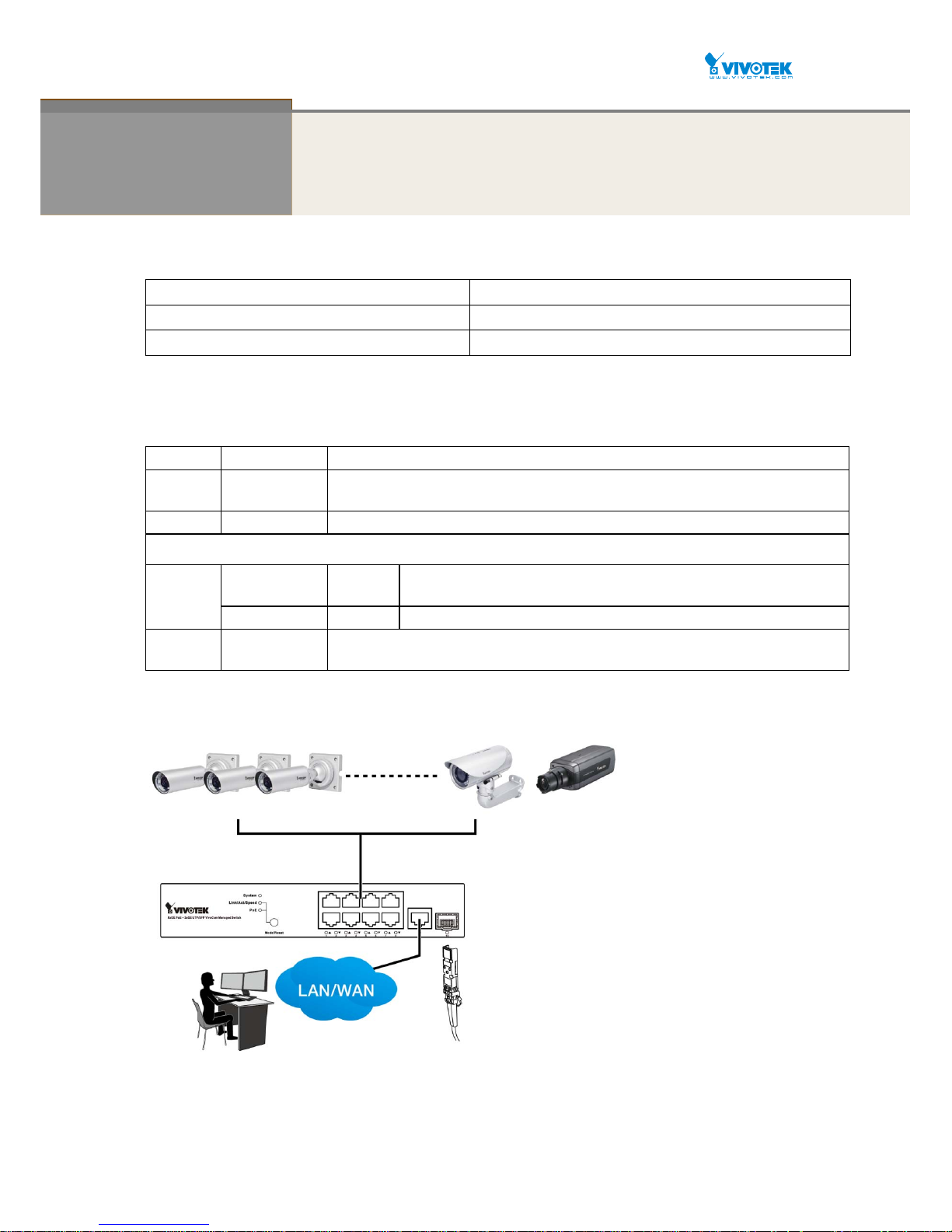
INTRODUCTION
Overview
This user’s manual provides installation and configuration details through a web
console (via the RJ-45 Ethernet connection).
The AW-GEV-104A series, the next generation L2 SNMP managed PoE switch, is a
portfolio of affordable managed switches that prov ides a reliable infrastructure for your
business network. These switches deliver more intelligent features and improve the
availability of your critical business applications, protect your sensitiv e information, and
optimize your network bandwidth to deliver information and applications more effectively.
It provides the ideal combination of affordability and capabilities for entry level networking
including small business or enterprise applications and helps you create a more efficient
workforce.
The AW-GEV-104A L2 SNMP managed sw itch provides 26 ports in a single device;
the specifications are highlighted as follows.
L2+ features provide better manageability, security, QoS, and performanc e.
Support IPv4/IPv6 dual stack management
Support SSH/SSL secured management
Support SNMP v1/v2c/v3
Support RMON groups 1,2,3,9
Support IGMP v1/v2/v3 Snooping
Support RADIUS authentication
Support IP Source Guard
Support DHCP Snooping
Support ACL and QCL for traffic filtering
Support 802.1d(STP), 802.1w(RSTP) and 802.1s(MSTP)
Support LACP and static link aggregation
Support Q-in-Q double tag VLAN
Overview of this user’s manual
Chapter 1 “Hardware Installation”
Chapter 2 “Operation of Web-based Management”
Chapter 3 “System Configuration”
Chapter 4 “Configuration”
Chapter 5 “Security”
Chapter 6 “Maintenance”
Chapter 7 “Surveillance Management” (Sur veillance users can start from this
chapter)
Chapter 8 “Surveillance Graphic View”
Chapter 9 “Surveillance Network”
Chapter 10 “Surveillance Monitor”
Chapter 11 “Surveillance Diagnostics”
Chapter 12 “Surveillance Maintenance”
User Manual rev. 1.1. Aug. 2015
11
Chapter 1 Hardware Installation
Package Contents
1x PoE switch 1x Quick Installation Guide
2x rack mount ears 1x power cord (type by the shipped-to area)
1x CD-ROM
LED Definitions
System
Green ON
Lit when power is on and normal. Off when power is disconnected.
Link/ACT/S
peed
Green
Lit Green when displaying Link/ACT/Speed status of Ethernet ports
(selected by the Mode button)
PoE
Green
Lit Green when displaying the PoE link status with powered devices.
Below are the LEDs below the Ethernet and SFP ports:
Ethernet
port LED
TP Speed
Green
/Yellow
Green when TP link is on 1000Mbps
Yellow when TP link is on 10/100Mbpx
PoE (Link/ACT) Green Green when PoE linked with powered device and supplying power to them.
SFP speed
Green/Yellow Green when SFP link is on 1Gbps
Yellow when SFP link is on 100Mbps
Connections
Front Panel
User Manual rev. 1.1. Aug. 2015
12
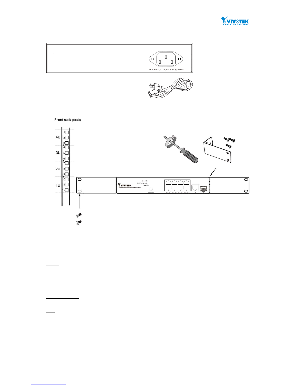
Rear Panel
Rack Mounting
Hardware Reset / Mode Button
The reset button is used to reboot the PoE switch or to restore the factory default settings. Sometimes resetting
the system can return the PoE switch to normal operation. If the system problems remain after reset, restore the
factory settings and try again.
Reboot: Press 3~10 seconds and release the recessed reset button. Wait for the PoE Switch to reboot.
Reset to factory default: Press >10 seconds and release the recessed reset button. Wait for the PoE Switch to
reset to factory default & Reboot.
The mode button is use to switch LED indicator’s mode.
Link / ACT/ Speed: Press <3 seconds and release the recessed mode button. The Link / ACT/ Speed LED will on.
Green when displaying Link/ACT/Speed status of Ethernet ports.
PoE : Press <3 seconds and release the recessed mode button. The PoE LED will on.
Green when displaying the PoE link status with powered devices.

User Manual rev. 1.1. Aug. 2015
13
Chapter 2 Operation of Web-based Management
Initial Configuration
IMPORTANT:
1. It is recommended to use IE10 or IE11 to open a web console with the PoE switch.
2. This PoE switch is specifically des igned for surveilla nce applications. I t comes with an inte grated
Surveillance interface for ease of configuration. The Surveillance interface is accessed through
a tabbed menu, and the configuration changes made in its window have a higher priority than
those in the Switch configuration menus.
3. You should save the configuration changes made on the Surve illance menus before lea ving the
web page. Otherwise, your configuration changes will be lost. The save button is located on the
upper right corner of the screen.
This chapter instructs you how to configure and manage the
AW-GEV-104A through the web user
interface.
With this facility, you can eas ily access and monitor through any one port of the switch all
the status of the switch, including MIBs status, each port activity, Spanning tree status, port
aggregation status, multicast traffic, VLAN and priority status, even illegal access record and so on.
The default values of the AW-GEV-104A are listed in the table below:
IP Address
DHCP client
Subnet Mask
255.255.255.0
Default Gateway
N/A
Username
admin
Password
admin
User Manual rev. 1.1. Aug. 2015
14
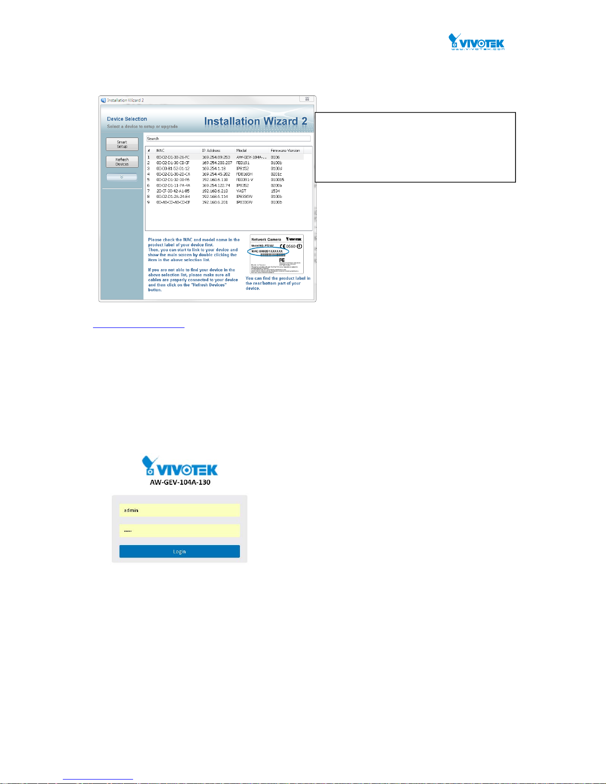
You can find the PoE switch using VIVOTEK’s IW2 utility. If network address conflicts occur, use this utility to
locate the PoE switch.
If you enabled the onboard DHCP server on the PoE switch, you can browse it. For instance, type
http://192.168.1.1 in the address row in a browser, it will display the following screen and ask
you to enter a username and password in order to login and access authentication.
The default username is “admin” and password is admin. For the first time to use, please enter the
default username and password, and then click the <Login> button. The login pr ocess now is
completed. In this login menu, you have to input the complete username and password resp ectively,
the AW-GEV-104A will not give you a shortcut to username automatically. This looks inconvenient,
but safer.
The AW-GEV-104A allows two or more users to manage the switch using the administrator’s identity.
The configuration changes made will take effect depending on who made the last configuration
change.
Figure 1 The login page
Ifyoudouble‐clickontheentryfoundonthe
IW2utility,anIEconsolewillbeopened.If
youpreferusingFirefoxorGoogleChrome,
youcanmanuallyentertheIPaddressin
yourbrowser’sURLfield.

User Manual rev. 1.1. Aug. 2015
15
NOTE:
When you login the Switch WEB/CLI to manager. You must first type the Username of the admin.
Use “admin” as the default password, so when you type after the end Username, please press
enter. Management page to enter WEB/CLI.
When you login the PoE switch series Web UI management, you can use both ipv4 ipv6 login to
manage
To optimize the display effect, we recommend you using the below browser and OS combinations:
Chrome
after v.39
Chrome
Before v38
FireFox v.39 IE11 IE10 IE9 IE8
WinXP No Yes Yes --- --- --- No
Win7 No Yes Yes Yes Yes No No
Win8/8.1 No Yes Yes Yes Yes No No
N
OTE:
The PoE switch and all cameras attached must be configured in the same subnet. Otherwise,
the Surveillance-related functions will not apply. You can let the PoE switch be a DHCP client
(listening to a DHCP server for IP assignment), or enable its onboard DHCP server.
User Manual rev. 1.1. Aug. 2015
16
Chapter 3
Switch- System Configuration
This chapter describes the entire basic configuration tasks which includes the System
Information and any manage of the Switch (e.g. Time, Account, IP, Syslog and NTP.)
3-1 System
You can identify the system by configuring the contact information, name, and location of the
switch.
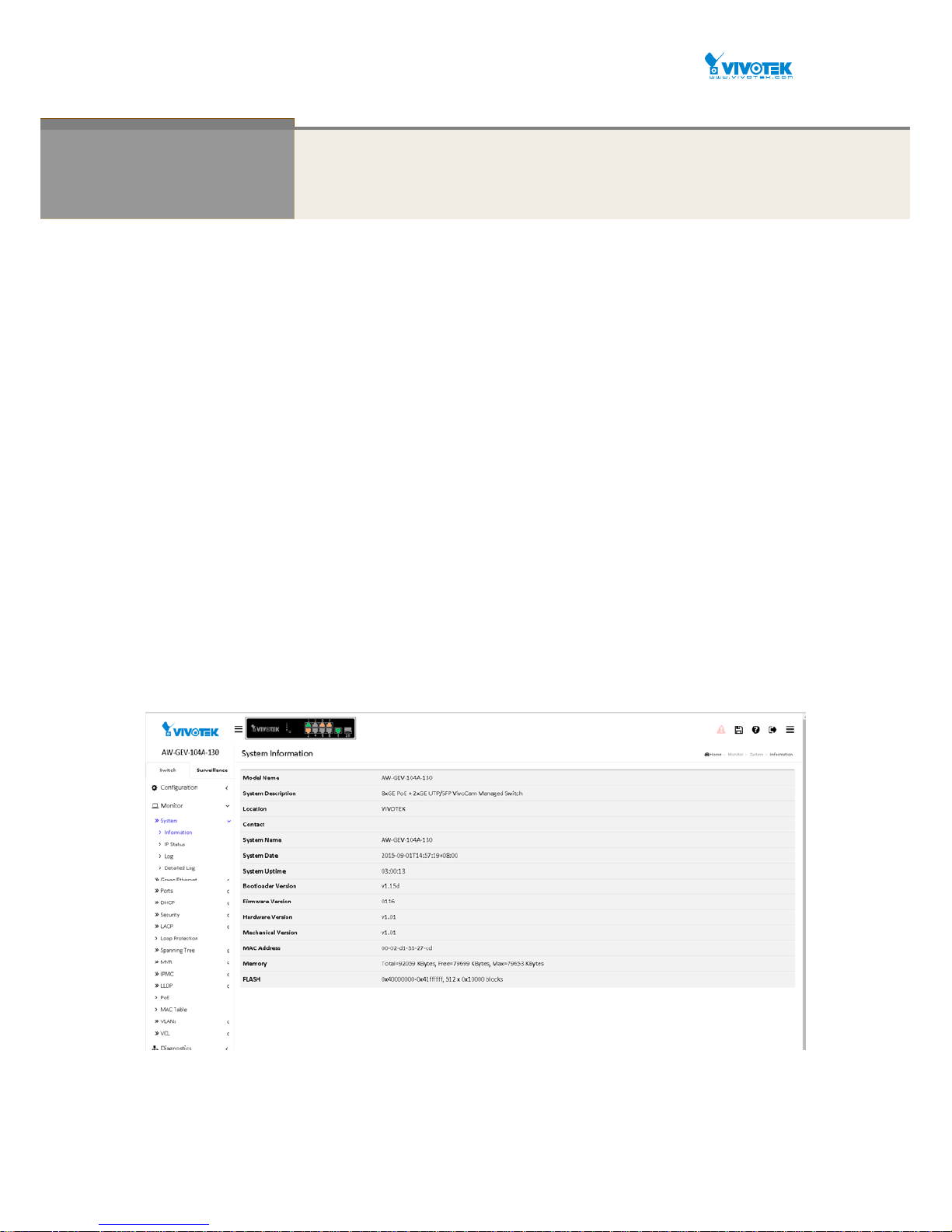
3-1.1 Information
The switch system’s contact information is provided here.
Web interface
To configure System Information in the web interface:
1. Click Configuration, System, and Information.
2. Write System Contact, System Name, System Location information in this page.
3. Click Apply.
Figure 3-1.1: System Information
Parameter description:
System Contact:
The textual identification of the contact person for this managed node, together

User Manual rev. 1.1. Aug. 2015
17
with information on how to contact this person. The allowed string length is 0 to
128, and the allowed content is the ASCII characters from 32 to 126.
System name:
An administratively assigned name for this managed node. By convention, this is
the node's fully-qualified domain name. A domain name is a text string drawn
from the alphabet (A-Z a-z), digits (0-9), minus sign (-). No space char acters are
permitted as part of a name. The first character must be an alpha chara cter. And
the first or last character must not be a minus si gn. The allowed string length is 0
to 128.
System Location:
The physical location of this node(e.g., telephone closet, 3rd floor). The allowed
string length is 0 to 128, and the allowed content is the ASCII char acters from 32
to 126.
User Manual rev. 1.1. Aug. 2015
18
3-1.2 IP
The IPv4 address for the switch could be obtained via DHCP Server for VLAN 1. To manually
configure an address, you need to change the switch's default settings to values that are
compatible with your network. You may also need to establish a default gateway between the
switch and management stations that exist on another network segment.
Configure the switch-managed IP information on this page
Configure IP basic settings, control IP interfaces and IP routes.
The maximum number of interfaces supported is 8 and the maximum number of routes is 32.
Web Interface
To configure an IP address in the web interface:
1. Click Configuration, System, IP.
2. Click Add Interface then you can create new Interface on the switch.
3. Click Add Route then you can create new Route on the switch
4. Click Apply
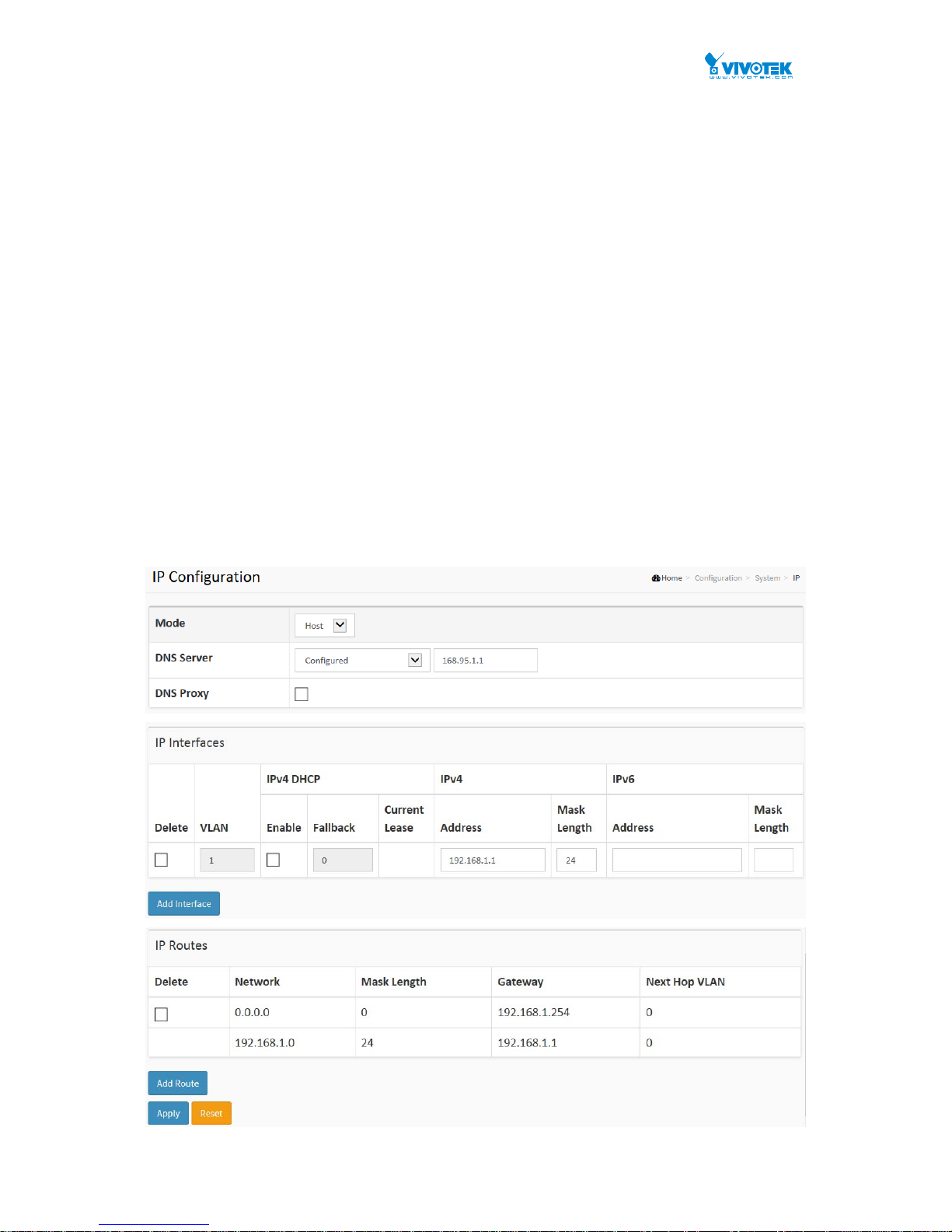
Figure 3-1.2: The IP configuration

User Manual rev. 1.1. Aug. 2015
19
Parameter description:
IP Configuration
Mode:
Configure whether the IP stack should act as a Host or a Router. In Host mode, IP traffic
between interfaces will not be routed. In Router mode traffic is routed between all
interfaces.
DNS Server
This setting controls the DNS name resolution done by the switch. The following modes are
supported:
From any DHCP interfaces
The first DNS server offered from a DHCP lease to a DHCP-enabled interface will be
used.
No DNS server
No DNS server will be used.
Configured
Explicitly provide the IP address of the DNS Server in dotted decimal notation.
From this DHCP interface
Specify from which DHCP-enabled interface a provided DNS server should be
preferred.
DNS Proxy
When DNS proxy is enabled, system will relay DNS requests to the currently configured
DNS server, and reply as a DNS resolver to the client devices on the network.
IP Interfaces
Delete
Select this option to delete an existing IP interface.
VLAN
The VLAN associated with the IP interface. Only ports in this VLAN will be able to access
the IP interface. This field is only available for input when creating an new interface.
IPv4 DHCP Enabled
Enable the DHCP client by checking this box. If this option is enabled, the system will
configure the IPv4 address and mask of the interface using the DHCP protocol. The DHCP
client will announce the configured System Name as hostname to provide DNS lookup.
IPv4 DHCP Fallback Timeout
The number of seconds for trying to obtain a DHCP lease. After this period expires, a
configured IPv4 address will be used as IPv4 interface address. A value of zero disables
the fallback mechanism, such that DHCP will keep retrying until a valid lease is obtained.
Legal values are 0 to 4294967295 seconds.
IPv4 DHCP Current Lease
For DHCP interfaces with an active lease, this column show the current interface address,
as provided by the DHCP server.
IPv4 Address
The IPv4 address of the interface in dotted decimal notation.
If DHCP is enabled, this field is not used. The field may also be left blank if IPv4 operation
on the interface is not desired.
IPv4 Mask
The IPv4 network mask, in number of bits (prefix length). Valid values are between 0 and 30
bits for a IPv4 address.
If DHCP is enabled, this field is not used. The field may also be left blank if IPv4 operation
on the interface is not desired.
IPv6 Address

User Manual rev. 1.1. Aug. 2015
20
The IPv6 address of the interface. A IPv6 address is in 128-bit records represented as eight
fields of up to four hexadecimal digits with a colon separating each field (:). For example,
fe80::215:c5ff:fe03:4dc7. The symbol :: is a special syntax that can be used as a shorthand
way of representing multiple 16-bit groups of contiguous zeros; but it can appear only once.
It can also represent a legally valid IPv4 address. For example, ::192.1.2.34.
The field may be left blank if IPv6 operation on the interface is not desired.
IPv6 Mask
The IPv6 network mask, in number of bits (prefix length). Valid values are between 1 and
128 bits for a IPv6 address.
The field may be left blank if IPv6 operation on the interface is not desired.
IP Routes
Delete
Select this option to delete an existing IP route.
Network
The destination IP network or host address of this route. Valid format is dotted decimal
notationor a valid IPv6 notation. A default route can use the value 0.0.0.0or IPv6 :: notation.
Mask Length
The destination IP network or host mask, in number of bits (prefix length). It defines how
much of a network address that must match, in order to qualify for this route. Valid values
are between 0 and 32 bits respectively 128 for IPv6 routes. Only a default route will have a
mask length of 0 (as it will match anything).
Gateway
The IP address of the IP gateway. Valid format is dotted decimal notationor a valid IPv6
notation. Gateway and Network must be of the same type.
Next Hop VLAN (Only for IPv6)
The VLAN ID (VID) of the specific IPv6 interface associated with the gateway.
The given VID ranges from 1 to 4094 and will be effective only when the corresponding
IPv6 interface is valid.
If the IPv6 gateway address is link-local, it must specify the next hop VLAN for the gateway.
If the IPv6 gateway address is not link-local, system ignores the next hop VLAN for the
gateway.
Buttons
Add Interface:
Click to add a new IP interface. A maximum of 8 interfaces is supported.
Add Route:
Click to add a new IP route. A maximum of 32 routes is supported.
Apply:
Click to save changes.
Reset:
Click to undo any changes made locally and revert to previously saved values.
User Manual rev. 1.1. Aug. 2015
21
3-1.3 NTP
NTP is Network Time Protocol and is used to sync the network time based Greenwich Mean
Time (GMT). If use the NTP mode and select a built-in NTP time server or manually specify an
user-defined NTP server as well as Time Zone, the switch will sync the time in a short after
pressing <Apply> button. Though it synchronizes the time automatically, the precondition is
that the switch must have the access to Internet.
Time Zone is an offset time off GMT. You have to select the time zone first and then perform
time sync via NTP because the switch will combine this time zone offset and updated NTP time
to come out the local time, otherwise, you will not able to get the correct time. The switch
supports configurable time zone from –12 to +13 step 1 hour.
Default Time zone: +8 Hrs.
Web Interface
To configure NT P in the web interface:
1. ClickConfiguration,System,NTP.
2. SpecifytheTimeparameterinmanualparameters.
3. ClickApply.
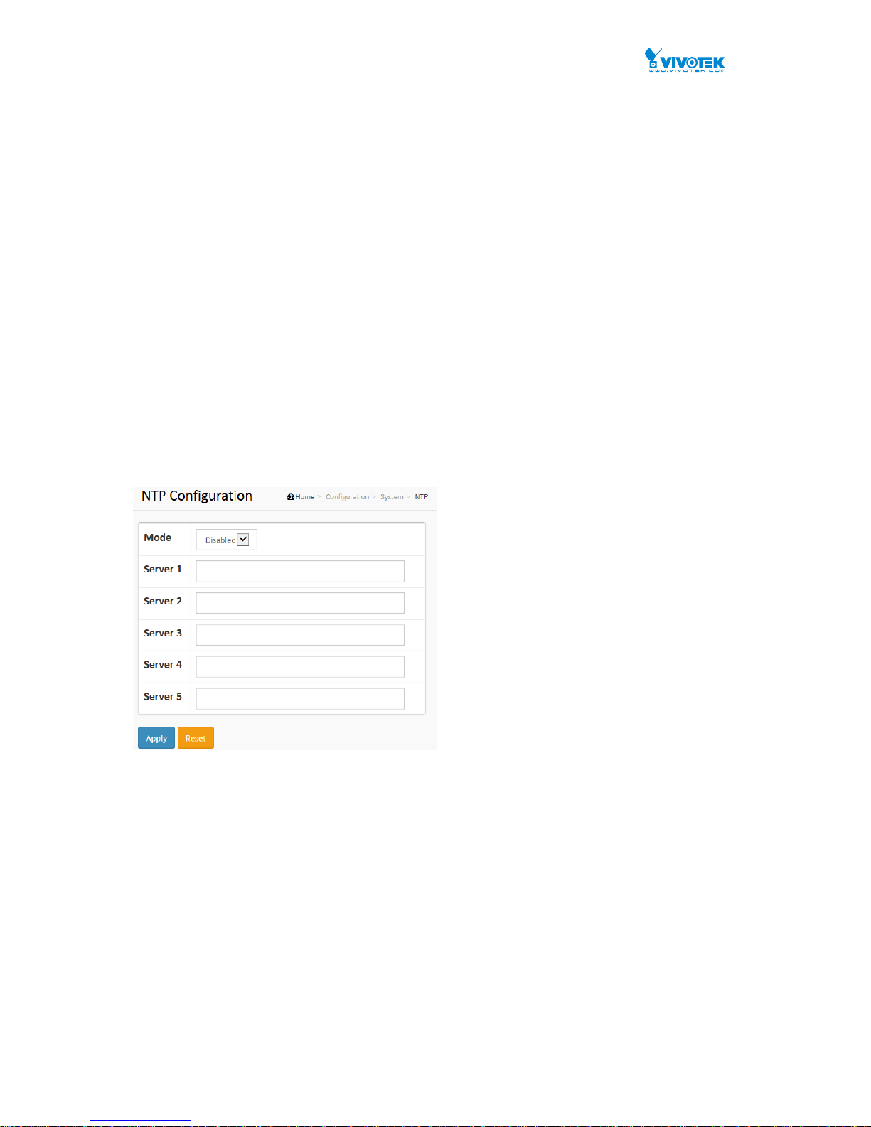
Figure 3-1.3: The NTP configuration
Parameter description:
Mode :
Indicates the NTP mode operation. Possible modes are:
Enabled: Enable NTP client mode operation.
Disabled: Disable NTP client mode operation.
Server 1 to 5 :
Provide the NTP IPv4 or IPv6 address of this switch. IPv6 address is in 128-bit
records represented as eight fields of up to four hexadecimal digits with a colon
separating each field (:). For example, 'fe80::215:c5ff:fe03:4dc7'. The symbol
'::' is a special syntax that can be used as a shorthand way of representing
multiple 16-bit groups of contiguous zeros; but it can only appear once. It can
also represent a legally valid IPv4 address. For example, '::192.1.2.34'.
Buttons
These buttons are displayed on the NTP page:
User Manual rev. 1.1. Aug. 2015
22
Apply – Click to save changes.
Reset - Click to undo any changes made locally and revert to previously saved
values.
3-1.4 Time
The switch provides manual and automatic ways to set the system time via NTP. Manual
setting is simple and you just input “Year”, “Month”, “Day”, “Hour” and “Minute” within the valid
value range indicated in each item.
Web Interface
To configure Ti m e in the web interface:
1. Click Configuration, System and Time
2. Specify the Time parameter.
3. Click Apply.
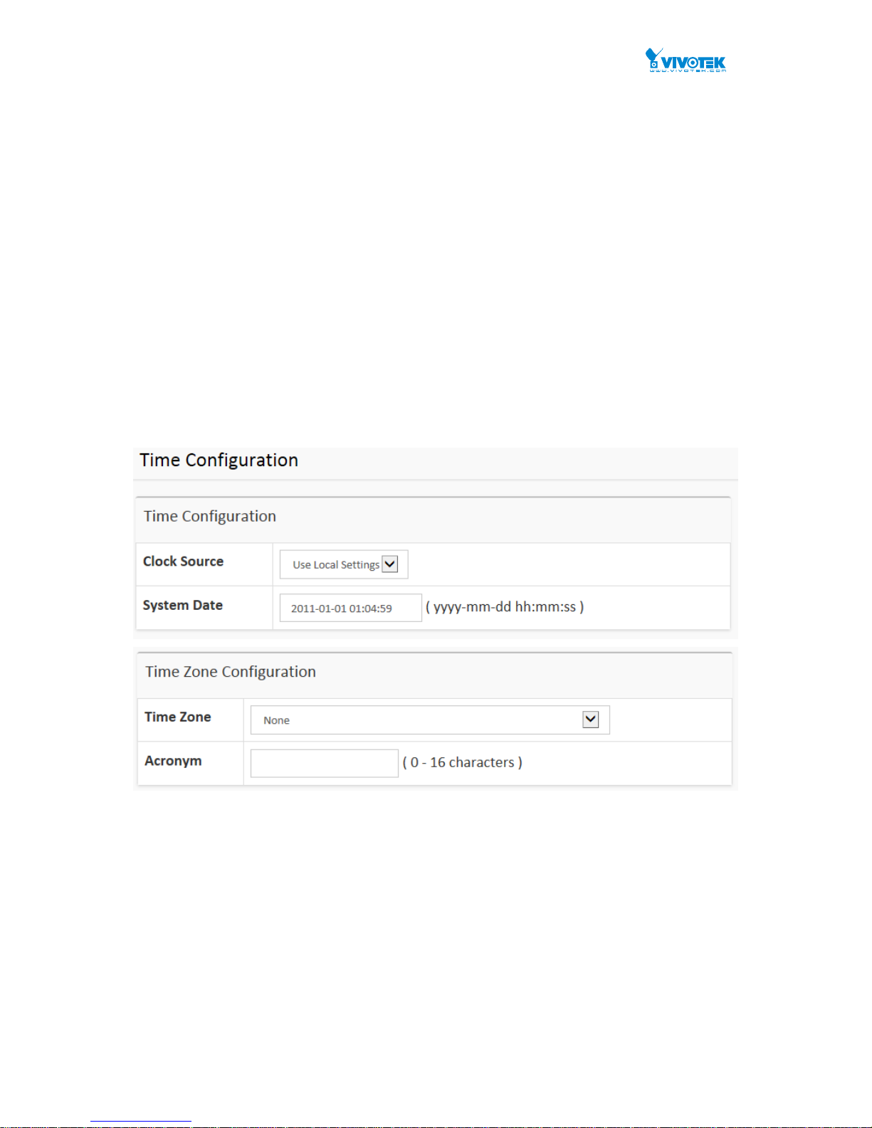
Figure 3-1.4: The time configuration
User Manual rev. 1.1. Aug. 2015
23
Parameter description:
Time Configuration
Clock Source:
There are two modes for configuring how the Clock Source from. Select "Use
Local Settings" : Clock Source from Local Time. Select "Use NTP Server" : Clock
Source from NTP Server.
System Date:
Show the current time of the system. The year of system date limits between
2011 and 2037.
Time Zone Configuration
Time Zone:
Lists various Time Zones worl d wide. Select appropriate Time Zone from the drop
down and click Apply to set.
Acronym:
User can set the acronym of the time zone. This is a User configur able acronym to
identify the time zone. (Range : Up to 16 characters )
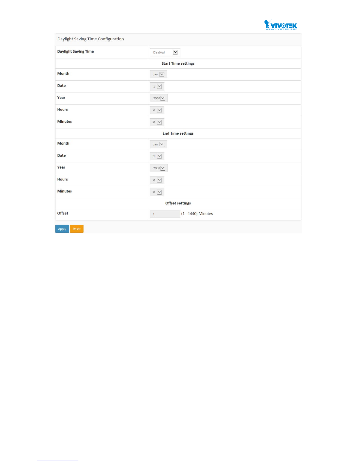
Daylight Saving Time Configuration
Daylight Saving Time:
This is used to set the clock forward or backward according to the configurations
set below for a defined Daylight Saving Time duration. Select 'Disable' to disable
the Daylight Saving Time configuration. Select 'Recurring' and configure the
Daylight Saving Time duration to repeat the configuration every year. Select
'Non-Recurring' and configure the Daylight Saving Time duration for single time
configuration. ( Default : Disabled ).

User Manual rev. 1.1. Aug. 2015
24
Recurring Configuration
Start time settings:
Week - Select the starting week number.
Day - Select the starting day.
Month - Select the starting month.
Hours - Select the starting hour.
Minutes - Select the starting minute.
End time settings:
Week - Select the ending week number.
Day - Select the ending day.
Month - Select the ending month.
Hours - Select the ending hour.
Minutes - Select the ending minute.
Offset settings:
Offset - Enter the number of minutes to add during Daylight Sa ving Time. ( Range:
1 to 1440 )
NOTE: The under “Start Time Settings
”
and “End Time
Settings” was displayed what you set on the “Start Time
Settings” and “End Time Settings” field information.
Buttons
These buttons are displayed on the NTP page:
Apply – Click to save changes.
Reset - Click to undo any changes made locally and revert to previously saved
values.
User Manual rev. 1.1. Aug. 2015
25
3-1.5 Log
The log is a standard for logging program messages . It allows separation of the software that
generates messages from the system that stores them and the software that reports and
analyzes them. It can be used as well a generalized informational, analysis and debugging
messages. It is supported by a wide variety of devices and receivers across multiple platforms.
Web Interface
To configure log configuration in the web interface:
1. Click Configuration, System and log.
2. Specify the syslog parameters include IP Address of Syslog server and Port number.
3. Evoke the Syslog to enable it.
4. Click Apply.
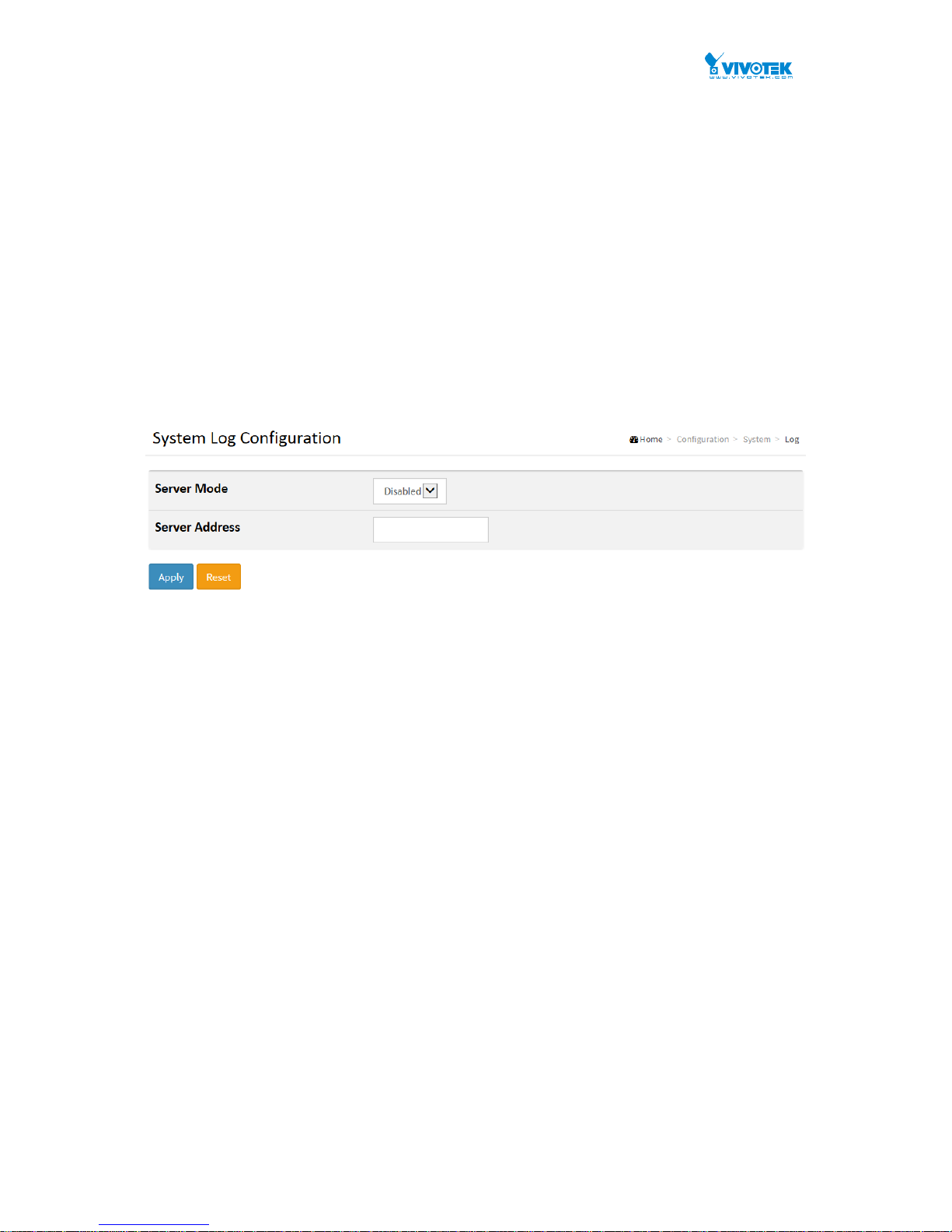
Figure 3-1.5: The System Log configuration
Parameter description:
Server Mode :
Indicate the server mode operation. When the mode operation is enabled, the
syslog message will send out to syslog server. Th e syslog protocol is based on
UDP communication and received on UDP port 514 and the syslog server will not
send acknowledgments back sender since UDP is a connectionless protocol and it
does not provide acknowledgments. The syslog packet will alw ays send out even
if the syslog server does not exist. Possible modes are:
Enabled: Enable server mode operation.
Disabled: Disable server mode operation.
Server Address :
Indicates the IPv4 hosts address of syslog server. If the switch provide DNS
feature, it also can be a host name.
Syslog Level :
Indicates what kind of message will send to syslog server. Possible modes are:
Info: Send information, warnings and errors.
Warning: Send warnings and errors.
Error: Send errors.
Buttons
These buttons are displayed on the NTP page:
Apply – Click to save changes.
Reset - Click to undo any changes made locally and revert to previously saved
values.
User Manual rev. 1.1. Aug. 2015
26
3-2 Green Ethernet
EEE is a power saving option that reduces the power usage when there is low or no traffic
utilization.
EEE works by powering down circuits when there is no traffic. When a port gets data to be
transmitted all circuits are powered up. The time it takes to power up the circuits is named
wakeup time. The default wakeup time is 17 us for 1Gbit links and 30 us for other link speeds.
EEE devices must agree upon the value of the wakeup time in order to make sure that both the
receiving and transmitting device has all circuits powered up when traffic is transmitted. The
devices can exchange wakeup time information using the LLDP protocol.
EEE works for ports in auto-negotiation mode, where the port is negotiated to either 1G or 100
Mbit full duplex mode.
For ports that are not EEE-capable the corresponding EEE checkboxes are grayed out and
thus impossible to enable EEE for.
When a port is powered down for saving power, outgoing traffic is stored in a buffer until the
port is powered up again. Because there are some overhead in turning the port down and up,
more power can be saved if the traffic can be buffered up until a large burst of traffic can be
transmitted. Buffering traffic will give some latency in the traffic.
Web Interface
To configure a Port Power Saving Configuration in the web interface:
1. Click Configuration, Green Ethernet
2. Evoke to enable or disable the ActiPHY, PerfectReach, EEE and EEE Urgent Queues .
3. Click Apply.
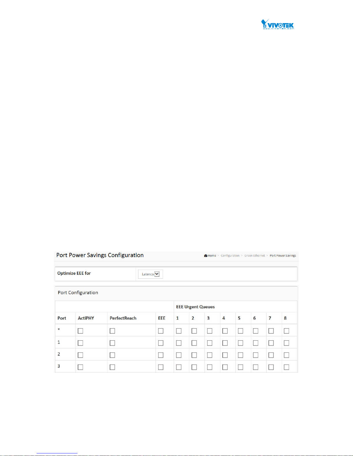
Figure 3-2.1: The Port Power Saving Configuration

User Manual rev. 1.1. Aug. 2015
27
Parameter description:
Optimize EEE for
The switch can be set to optimize EEE for either best power saving or l east traffic
latency .
Port:
The switch port number of the logical port.
ActiPHY :
Link down power savings enabled.
ActiPHY works by lowering the power for a port when there is no link. The port is
power up for short moment in order to determine if cable is inserted.
PerfectReach :
Cable length power savings enabled.
PerfectReach works by determining the cable length and lowering the power for
ports with short cables.
EEE :
Controls whether EEE is enabled for this switch port.
For maximizing power savings, the circuit isn't started at once transmit data is
ready for a port, but is instead queued until a burst of data is ready to be
transmitted. This will give some traffic latency.
If desired it is possible to minimize the latency for specific frames, by mapping the
frames to a specific queue (done with QOS), and then mark the queue as an
urgent queue. When an urgent queue gets data to be trans mitted, the circuits will
be powered up at once and the latency will be reduced to the wakeup time.
EEE Urgent Queues :
Queues set will activate transmission of frames as soon as data is available.
Otherwise the queue will postpone transmission until a burst of frames can be
transmitted.
User Manual rev. 1.1. Aug. 2015
28
3-3 Ports Configuration
The section describes to configure the Port detail parameters of the switch. Others you could
using the Port configure to enable or disable the Port of the switch. Monitor the ports content or
status in the function.
3-3.1 Ports
This page displays current port configurations. Ports can also be configured here.
Web Interface
To configure a Current Port Configuration in the web interface:
1. Click Configuration, Ports Configuration, and Ports
2. Specify the Speed Configured, Flow Control, Maximum Frame size, Excessive Collision
mode and Power Control.
3. Click Apply.
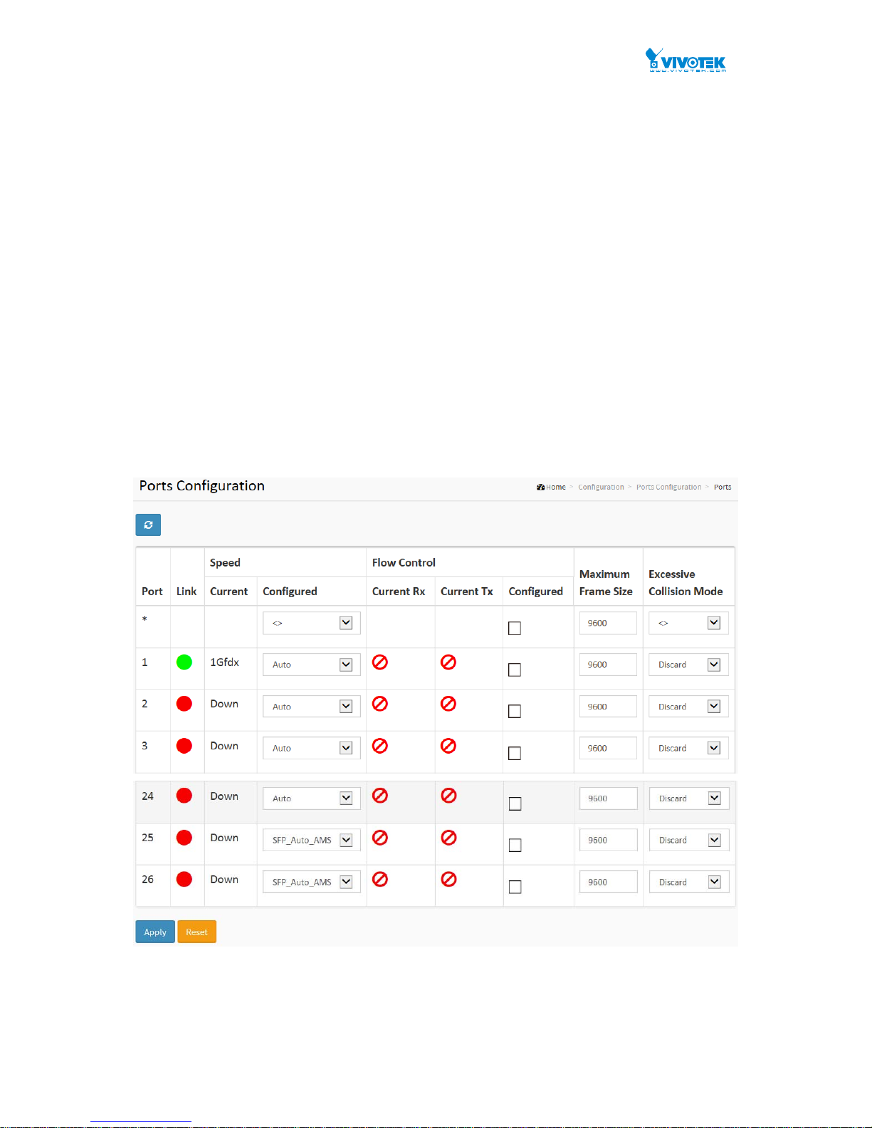
Figure 3-3.1: The Port Configuration
Parameter description:
Port :
This is the logical port number for this row.

User Manual rev. 1.1. Aug. 2015
29
Link :
The current link state is displayed graphically. Green indicates the link is up and
red that it is down.
Current Link Speed :
Provides the current link speed of the port.
Configured Link Speed :
Selects any available link speed for the given switch port. Only speeds supported
by the specific port is shown. Possible speeds are:
Disabled - Disables the switch port operation.
Auto - Port auto negotiating speed with the link partner and selects the highest
speed that is compatible with the link partner.
10Mbps HDX - Forces the cu port in 10Mbps half duplex mode.
10Mbps FDX - Forces the cu port in 10Mbps full duplex mode.
100Mbps HDX - Forces the cu port in 100Mbps half duplex mode.
100Mbps FDX - Forces the cu port in 100Mbps full duplex mode.
1Gbps FDX - Forces the port in 1Gbps full duplex
2.5Gbps FDX - Forces the Serdes port in 2.5Gbps full duplex mode.
SFP_Auto_AMS - Automatically determines the speed of the SFP. Note: There is
no standardized way to do SFP auto detect, so here it is done by reading the SFP
rom. Due to the missing standardized way of doing SFP auto detect some SFPs
might not be detectable. The port is set in AMS mode. Cu port is set in Auto mode.
100-FX - SFP port in 100-FX speed. Cu port disabled.
100-FX_AMS - Port in AMS mode. SFP port in 100-FX speed. Cu port in Auto
mode.
1000-X - SFP port in 1000-X speed. Cu port disabled.
1000-X_AMS - Port in A MS mode. SFP port in 1000-X speed. Cu port in Auto mode.
Ports in AMS mode with 1000- X speed has Cu port preferred. P orts in AMS mode
with 100-FX speed has fiber port preferred.
Flow Control :
When Auto Speed is selected on a port, this section indicates the flow control
capability that is advertised to the link partner. When a fixed-speed setting is
selected, that is what is used. The Current Rx column in dicates whether pause
frames on the port are obeyed, and the Current Tx column indicates whether
pause frames on the port are transmitted. The Rx and Tx settings are determined
by the result of the last Auto-Negotiation.
Check the configured column to use flow control. This sett ing is related to the
setting for Configured Link Speed.
Maximum Frame Size :
Enter the maximum frame size allowed for the switch port, including FCS.
Excessive Collision Mode :
Configure port transmit collision behavior.
Discard: Discard frame after 16 collisions (default).
Restart: Restart backoff algorithm after 16 collisions.
Buttons
Apply – Click to save changes.

User Manual rev. 1.1. Aug. 2015
30
Reset- Click to undo any changes made locally and revert to previously saved
values.
Upper right icon (Refresh)
You can click them for refresh the Port link Status by manual
 Loading...