

Page 1
Assembly
Guide
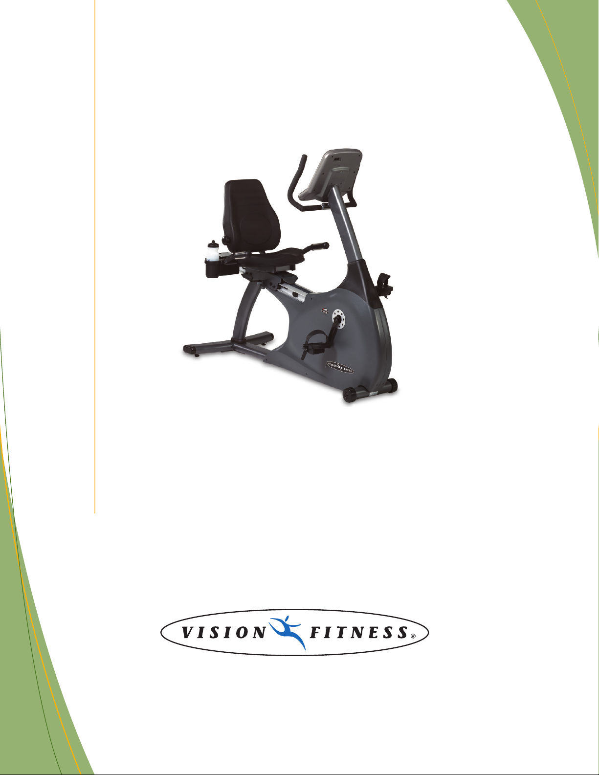
R2600HRT
COMMERCIAL FITNESS BIKE
Page 2
1
STEP
2
STEP
4
STEP
To avoid possible damage to this Fitness Bike, please follow these assembly steps in the correct order. Before proceeding, find your
new Fitness Bike’s serial number located on the front axle tube, and enter here:
Refer to this number when calling for service, and enter this serial number on your Warranty Card and in your own records. Be
sure to read your Owner’s Guide before using your new Fitness Bike.
If any parts, hardware or tools are missing, please call 1.800.335.4348, Extension 12
NOTE: It is recommended that you apply grease to the threads of each screw as you assemble your Fitness Bike to prevent loosen-
ing and noise. Also, during each assembly step, ensure that ALL screws are in place and partially threaded in before completely
tightening any ONE screw.
Assembly
Guide
R2600HRT
COMMERCIAL FITNESS BIKE
5
STEP
3
STEP
6
STEP
Page 3
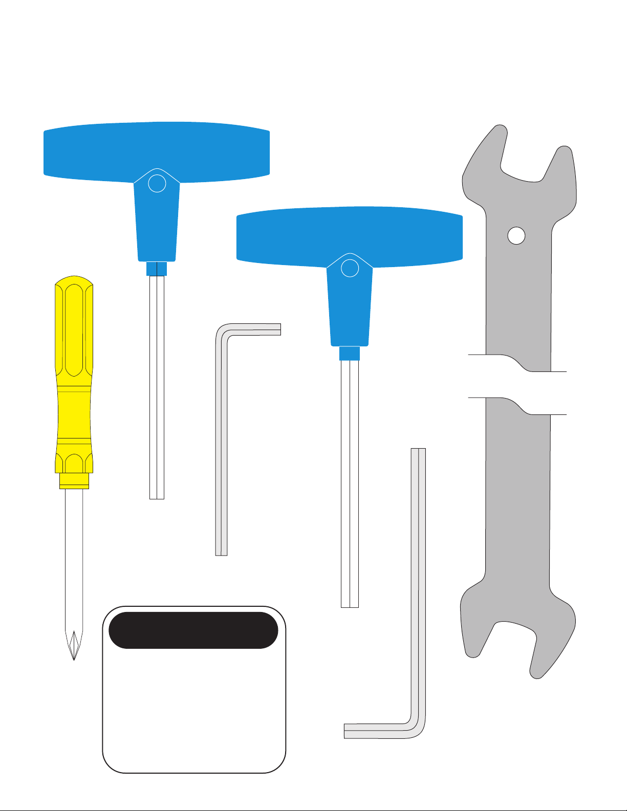
5mm Allen Wrench
Screwdriver
5mm L-Shaped Wrench
TOOLS & PARTS INCLUDED
4mm L-Shaped Wrench
PARTS BOX
Console Mast Cover
Water Bottle
Heart Rate Chest Strap
Color-coded Hardware Bags
Pedals/Straps
Owner’s Guide
Assembly Guide
Warranty Card
6mm Allen Wrench
15mm Pedal Wrench
Page 4

ORANGE BAG
GREEN BAG
PINK BAG
HARDWARE INCLUDED
BLUE BAG
M8 x 15L Screw
Quantity: 7
M8 x 20L Screw
Quantity: 2
M8x65L Screw
Quantity: 2
M8 Lock Washer
Quantity: 4
M8 Lock Washer
Quantity: 6
M8 x 15L Screw
Quantity: 2
M8 Lock Washer
Quantity: 2
BLACK BAG
M6 x 55L Screw
Quantity: 8
M6 Lock Washer
Quantity: 8
M8 x 15L Screw
Quantity: 4
M8 Lock Washer
Quantity: 8
M8 x 20L Screw
Quantity: 4
YELLOW BAG
M5 x 35L Screw
Quantity: 2
M5 Lock Washer
Quantity: 2
Page 5

5
2
STEP
• Slide the console mast boot onto the
console mast.
• Unfold the wire harness and heart
rate wires located in the console mast
frame bracket. Attach the wire tie
coming from the bottom of the console
mast to the wire harness and heart
rate wires. Pull the wire tie with wire
harness and heart rate wires up
through the top of the console mast
while simultaneously sliding the mast
into the frame bracket.
• Secure the console mast to the
frame bracket with six lock washers
(M8) and six screws (M8x15L).
Tighten with the 5mm Allen wrench.
Place the seventh screw (M8x15L) in
the rear of the frame bracket and
tighten until snug.
• Slide the console mast boot down
and snap it into place on the side cover.
BLUE BAG
1
STEP
• Install the rear foot with the four
lock washers (M8), two inside
screws (M8x65L), and two outside
screws (M8x20L). Tighten with the
5mm Allen wrench.
ORANGE BAG
1
STEP
2
STEP
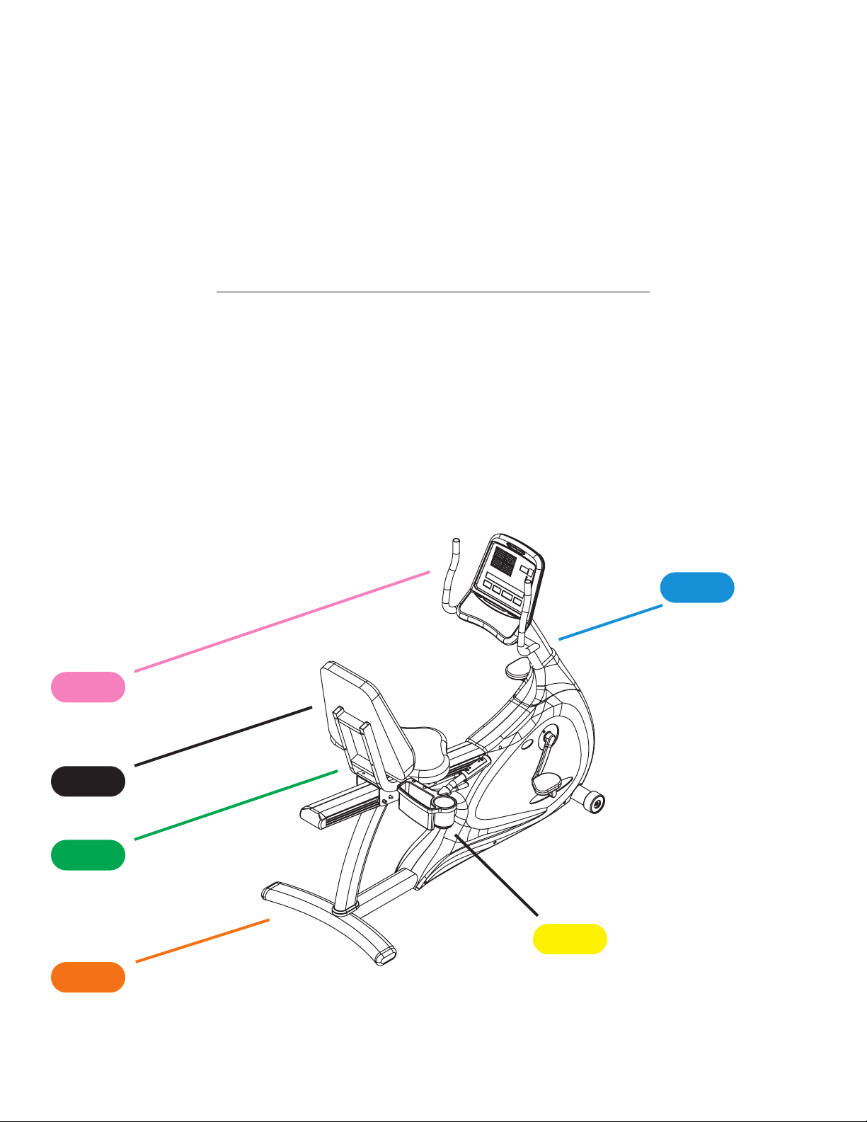
Console Mast
Console Mast
Boot
Frame
Bracket
Rear Foot
Page 6

6
3
STEP
• Mount the upper handlebars to the
console mast using two lock washers
(M8) and two screws (M8x15L).
Tighten with the 5mm Allen wrench.
• Remove the four mounting screws from
the back of the console. Connect the
wire harness and heart rate wires that
come from the console mast into the
plugs located in the back of the console.
Make sure the 9-Volt battery is plugged
in and in place on the console. Attach
the console to the mast with the four
screws removed earlier.
PINK BAG
3
STEP
Console Mast
Handlebar
Page 7

7
4
STEP
• Attach the seat frame to the sliding
seat bracket using four lock washers
(M8) and four socket head cap screws
(M8x20L) and the 6mm Allen wrench.
• Connect Wires A on the seat
handlebar to Wires B on the sliding
seat bracket. Attach the seat
handlebars to the sliding seat bracket
using four lock washers (M8) and four
screws (M8x15L). Tighten with the
5mm Allen wrench.
GREEN BAG
4
STEP
Wires B
Wires A
Seat Handlebar
Seat Frame
Sliding Seat
Bracket
Page 8

8
5
STEP
Lumbar Controlled
Seat Back
Seat Bottom
Plastic Seat
Cover
5
STEP
• Secure the Lumbar controlled seat
back and the seat bottom to the seat
frame with eight lock washers (M6)
and eight screws (M6x55L). Tighten
with the 4mm Allen wrench.
• Snap the plastic seat cover into
place on the back of the Lumbar
controlled seat.
BLACK BAG
Page 9

9
500 South CP Avenue • P.O. Box 280 • Lake Mills. WI 53551
toll free 1.800.335.4348 • phone 1.920.648.4090 • fax 1.920.648.3373
www.visionfitness.com
©2004 Vision Fitness. All Rights Reserved. 9.04 Part #Z26RB77-AG
AG18.30PRD
REV2
6
STEP
Accessory
Tray
Pedal
6
STEP
• Attach the left and right pedals to
the left and right crank arms. Tighten
the pedals using the 15mm Pedal
Wrench.
• Secure the Accessory Tray to the
seat handlebar with two screws
(M5x35L) and two lock washers
(M5). Tighten with the screwdriver.
YELLOW BAG
 Loading...