

Page 1
g
g
g
g
g
g
g
g
g
g
g
May 21, 1998
OBSOLETE
TECHNICAL DATA
Sprinkler 141 a
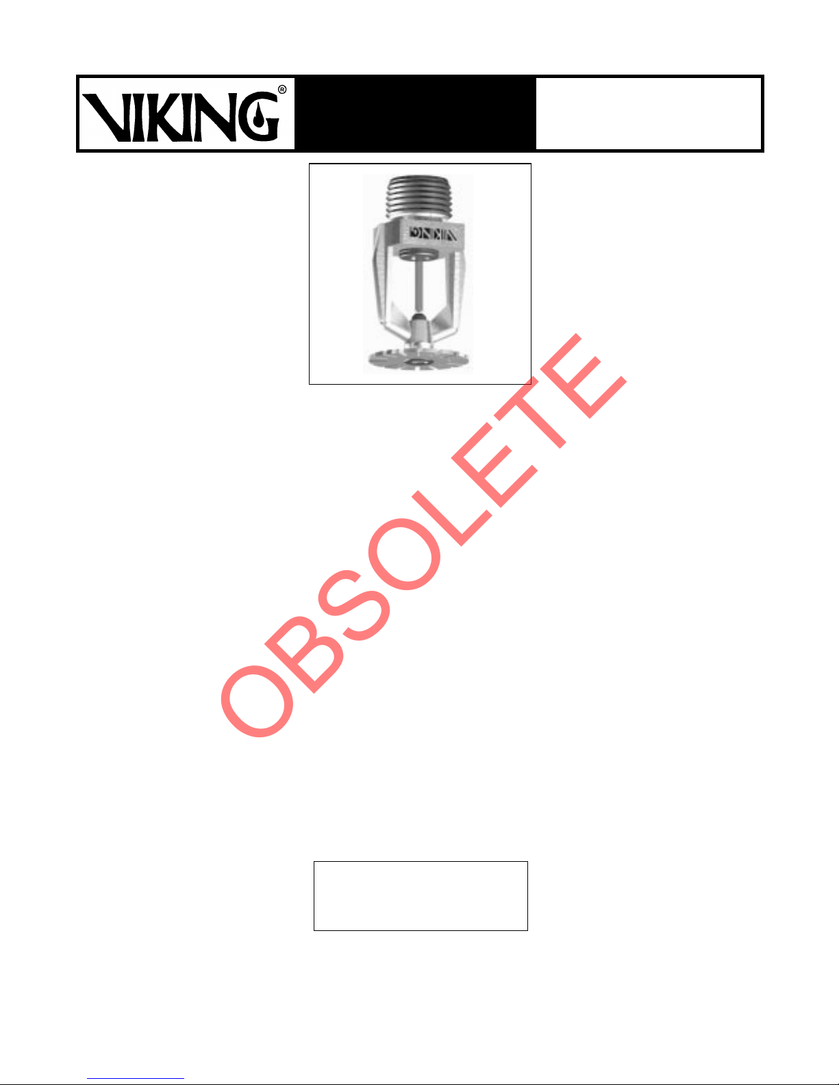
Microfast® MODEL M-5
RESIDENTIAL PENDENT
SPRINKLER, 5.5 K-FACTOR
1. PRODUCT NAME
VIKING Microfast® Model M-5
Residential Pendent Sprinkler
5.5 K-Factor
Base Part No. 10050
Manufactured since 1997.
2. MANUF ACTUR ER
THE VIKING CORPORATION
210 N. Industrial Park Road
Hastings, Michigan 49058, U.S.A.
Telephone: (616) 945-9501
Fax Number: (616) 945-9599
From outside the U .S. A.:
Telephone: +1 (616) 945-9501
Fax Number: +1 (616) 945-9599
e-mail: techs vc s@v ik in gcorp.com
(800) 968-9501
3. PRODUCT DESC RIPTIO N
The Viking Mi crofast® Model M-5 Residential Pendent Sprinkler is a small,
high-sensit ivity, glass-bulb spray sprinkler. The sprinkler is available in several
finishes and temperatur e ratings to meet
design requ irements.
The sprinkler is listed for use below
smooth, flat, h orizontal ceilings and
ceilings with slo pes up to an d including a 6/12 p itch (26.6°), with spacings
up to 20’ by 20’.
The sprinkler design, with a K-Factor of
5.5, allows efficient use of available
water suppl ies for the hydrau lically designed fire-protection system. The
small, rugged 3mm glass bulb and special deflector combine speed of operation and areas of cov erage to meet the
residential sprinkler standards. During
fire conditions , the heat-sensit ive liquid
in the glass bulb expands, causing the
bulb to shatter, releasing the pip cap and
sealing spring assembly. The water
flowing through the sprinkler orifice
strikes the sprinkler deflector, forming a
uniform spray pattern to extinguish or
control the fire.
4. TECHNICAL DATA
See approval charts (pages 141 c and
141 d) for listings.
Rated to 1 75 PSI (1 207 kP a) water
working pressure.
Factory tested pneumatically to 95 PSI
(655 kPa).
See approval charts for minimum water
supply requirements and maximum
areas of coverage.
Glass-bulb fluid temperature rated to
-65°F (-55°C).
Spring: USA Patent No. 4,570,720
Units of measure in parentheses may be approximations.
Form No. F_ 060697
See pages 141 c and 141 d for
temperature ratings.
Thread Size: Nominal 1/2" (15mm) NPT
K Factor: 5.5
* Metric K Factor shown is for use
when pressure is measured in kPa.
When pressure is measured in BAR,
multiply the metric K Factor shown by
10.0.
Finishes:
Enloy® (patents pending), White
(Paint), and Navajo Wh ite (Paint)
Materials:
Frame - Brass Castings UNS-C84400
Deflector - Brass UNS-C26000
Bulb - Glass
Nominal 3mm diameter
Seal - Teflon
Spring - Nickel alloy
Screw - Brass UNS-C36000
Pip Cap - Copper UNS-C14500
Accessories:
Refer to the "Sprinkler Accessories" of
the
Viking Engineering and Design Data
book for approved sprinkler wrench and
other accessories.
(7,9 metric*)
Bright Brass, Chrome-
®
tape
5. AV AILABILITY AND SERVICE
Viking sprinklers are available through a
network of domes tic, Canadi an, an d international distributors. See the Yellow
Pages of the tele phon e dire ctory (l iste d
under “Sprinklers-Automatic-Fire”) or
write to The Viking Corporation.
Viking Technical Data may be found on
The Viking Corporation’s Web site,
located at http://www.vikingcorp.com.
The Web site may include a more recent
edition of this Technical Data page.
6. GUARANTEES
For details of warranty, refer to Viking’s
current list price schedule or contact Vikin
directly.
Replaces sprinkler page 141 a-e, dated Ap ril 9, 1998
(added reference to Viking’s website and mad e a
correction in the approval chart on page 141 d).
7. INST A LLATION
WARNING:
factured and tested to meet the ri
requirements of the approving agency.
The sprinklers are designed to be installed in accordance with recognized
installation standards. Deviation from
the standards or any alteration to the
sprinkler after it leaves the factory includin
ing, coating, or modification, may render
the sprinkle r inoperative and wi ll automatically nullify the approval and any
uarantee made by The Viking Corporation.
A. Sprinklers are to be installed in ac-
cordance with the latest published
standards of the National Fire Protection Association, Factory Mutual,
Loss Prevention Council, Asse mblee
Pleniere, Verband der Sachversicherer or o ther similar or
tions, and a lso with pr ovisions of governmental codes, ordinances, and
standards whenever applicable. For
conditions not specifically covered by
the standar ds, re fer to the "Vikin
Residential Installation Guide".
nal approval and acceptance of all
Residentia l Sprinkle r Installa tions
must be obtained from the Authority Havi ng Juri sdicti on.
tial sprinklers are special-service
sprinklers for use in one- and twofamily dwellin
residential p ortions of ot her occupancies, where all owed. The use of res idential sprinklers may be limited due
to occupancy and hazard. The minimum flow rate indicate d for a listed
area of cove ra
the sprinkler. Therefore, the system
must be hydrauli cally calc ulated.
Refer to the Auth ority Having Jurisdiction prior to installation.
B. Sprinklers must be handled with care.
They must b e stored in a cool, dr y
place in their ori
Never install sp rinklers that have
been dropped or damaged in any
way. Never install any
sprinkler if the bulb is cracked or if
there is a loss of liquid from the bulb.
If a glass bu lb lack s the approp riate
amount of fluid, it should be set aside
and returned to Viking (or an authorized Vikin
soon as possible. If the sprinkler is
Viking sprinklers are manu-
, but not limited to, painting, plat-
aniza-
Fi-
Residen-
s, mobile homes , and
e must be prov ided at
inal container.
lass-bulb
distributor) for analysis as
id
Page 2

y
g
y
y
g
g
g
g
g
g
g
y
y
g
y
y
y
g
y
y
y
g
g
g
y
g
g
y
y
y
y
Sprinkler 141 b
OBSOLETE
TECHNICAL DATA
May 21, 1998
Microfast® MODEL M-5
RESIDENTIAL PENDENT
SPRINKLER, 5.5 K-FACTOR
not returned to Viking, it should be destroyed immediately. Never install
sprinklers which have been exposed
to temperatures in excess of maximum ambient te mperature allow ed.
Such sprinklers should be destr oyed
immediatel
C. Corrosion-resistant sprinklers must
be installed when subject to corrosive
atmosphe res. V iking Microfast
Model M-5 Residential Pendent
Sprinklers are not intended for use in
corrosive envi ro nm e nt s.
D. Use care when locatin
near fixtures that can generate heat.
Do not install sprinklers where the
will be exposed to temperatures that
exceed the maximum recommended
ambient tempe rature for the temperature rating used.
E. Sprinklers must be protected from
mechanical damage. Adequate heat
must be provided when sprinklers are
installed on wet pipe s
F. The Microf ast® Model M-5 Residential
Pendent Sprinkler must be installed
after the piping is in place to preven t
mechanical dama
stalled in the pendent position. Before installing, be sure the s prinkler is
the appropriat e model and s tyle, and
has the prope r orific e size , tempe rature ratin
teristics. Apply a small amount of
pipe-joint co mpound or tape to the
male threads only, taking care not to
allow a build- up of co mpound i nside
the orifice. Inst all the spri nkler on the
pipin
wrench only, while taking care not to
damage the sprinkle r operating parts.
DO NOT use the sprinkler deflector to
start or thre ad th e spri nkler into a fittin
.
G. After installation, the entire sprinkler
system must be tested in accordance
with the recognized installation
standards. The test is applied after
.
sprinklers
stems.
must
e, and
, and response charac-
using the special sprinkler
be in-
sprinkler inst allation to ensure that no
dama
e has occurred to the sprinkler
during shipment and installation, and
to make sure the unit has been properly tightened. If a thr ead leak shou ld
occur, normally the unit must be removed, new pipe-joint compound or
tape applied, and then reinstalled.
®
This is due to the fact that when the
joint seal leaks, the sealin
pound is washed out of the joint.
8. MAINTENANCE
NOTICE:
maintaining the fire-protection system
and devices in proper operatin
tion. For mini mum mainte nanc e and in spection requirements, refer to the National Fire Protection Association Pamphlet that describes care and maintenance of sprinkler s
the Authority Having Jurisdiction ma
have additional maintenance, testing,
and inspection requirements which must
be followed.
A. Sprinklers must be inspected on a
B. Sprink lers t hat have been field
C. The sprinkler discharge pattern is
The owner is responsible for
stems. In addition ,
re
ular basis for corrosion, mechanical damage, obstructions , pai nt, e tc.
The frequency of the inspections ma
vary due to corrosive atmospheres,
water supplies, and activity around
the device.
painted or mechanicall
must be replaced immediately. Sprinklers showing signs of corrosion shall
be tested and/or replaced immediatel
as required. Residential sprinklers that are 20 years old shall be
tested a nd/or replac ed as requir ed.
Never attempt to repair or reassemble a sprink ler. Sprin klers th at hav e
operated cannot be reassembled or
re-used, b ut must b e replac ed.
When replacin
new sprinklers.
critical for proper fire protection.
Nothing should be hung from, at-
sprinklers, use onl
com-
condi-
damaged
tached to, or othe rwise ob struct
the discharge pattern.
tions must be immediatel
or, if necessary, additional sprinklers
installed.
D. When replacing existing sprinklers ,
the s
stem must be removed from
service. Refer to the ap propriat e system description and/ or valv e i ns tr uctions. Prior to removing the system
from service, notify all Authorit ies
Havin
Jurisdi ction. Cons ideratio n
should be given to employment of a
fire patrol in the affected area.
1. Remove the system form service,
drain all water, and relieve all
pressure on the pipin
2. Using the special sprinkler wrench,
turn the unit counterclockwis e to
remove the old sp rinkle r from the
pipin
3. Install the ne w unit. Care must be
4. Place the s
E. Sprinkler s
subjected to a fire m ust be returned to
service as soon as possible. The entire s
damage, and repaired or replaced as
necessary. Sprinklers that ha ve been
exposed to co rrosive pr oducts of
combustion or high ambient temp eratures, but have not operated, should
be replaced. Refer to the Authorit
Having Jurisdiction for minimum replacement requirements.
in which it is inst al le d.
taken to ensure that the replacement sprink ler is the pr oper model
and st
le, and has the appropriate
orifice size, temperature ratin
and response characteristics.
Approvals and listings of the replacement sprinkler should match
those for the e xistin
fully stocked spare sprinkler cabinet should b e provided for t his purpose.
and secure al l v al ve s. Che ck an d
repair all leaks.
stem must be inspected for
stem back in service
stems that have been
All obstruc-
removed
.
sprinkler. A
,
Page 3

May 21, 1998
OBSOLETE
TECHNICAL DATA
Sprinkler 141 c
Microfast® MODEL M-5
RESIDENTIAL PENDENT
SPRINKLER, 5.5 K-FACTOR
Sprinkler Nominal Sprinkler
Temperature Temperature Rating Maximum Ambient Maximum Recommended Bulb
Classification (Fusing Point) Temperature Allowed
Ordinary 155°F (68°C)
Intermediate 175°F (79°C) 155°F (68°C
Sprinkler Finishes:
1
Based on National Fire Prevention and Control Administration, Contract No. 7-34860.
2
Based on NFPA-13. Other limits may apply depending on fire loading, sprinkler location, and other Authority-Having-Jurisdiction requirements.
Refer to specific installation standards.
Deflector Thread Nominal Nominal Overall
Style Size NPT Orifice K Factor
Pendent
Brass, Bright Brass, Chrome-Enloy
1/2 inch 1/2 inch 5.5 US 2.25 inch
(15 mm) (15 mm) (7,9 metric) (69,9 mm)
®
AREAS OF COVERAGE
Ceiling Temperature at Sprinkler
1
135°F (46°C)
, White (Paint), and Navajo White (Paint)
Ambient Temperature
)
9
4
100°
150°F (65°C) Yellow
2
F (38°C) Red
Length
A1X
Smooth, Flat, Horizontal Ceilings
Maximum Area
of Coverage
Width Length
12 ft. x 12 ft. 16 GPM @ 8.5 PSI 14.5 GPM @ 7.0 PSI
3,7 m x 3,7 m 60,6 L/Min @ 58,6 kPa 54,9 L/Min @ 48,3 kPa
14 ft. x 14 ft. 19 GPM @ 11.9 PSI 16 GPM @ 8.5 PSI
4,3 m x 4,3 m 71,9 L/Min @ 82,0 kPa 60,6 L/Min @ 58,6 kPa
16 ft. x 16 ft. 19 GPM @ 11.9 PSI 16 GPM @ 8.5 PSI
4,9 m x 4,9 m 71,9 L/Min @ 82,0 kPa 60,6 L/Min @ 58,6 kPa
18 ft. x 18 ft. 21 GPM @ 14.6 PSI 17.5 GPM @ 10.1 PSI
5,5 m x 5,5 m 79,5 L/Min @ 100,7 kPa 66,2 L/Min @ 69,6 kPa
20 ft. x 20 ft. 24 GPM @ 19.0 PSI 19 GPM @ 11.9 PSI
6,1 m x 6,1 m 90,8 L/Min @ 131,0 kPa 71,9 L/Min @ 82,0 kPa
Minimum Water Supply Requirements
6
One Sprinkler Two or More UL
7
A1X A1X
A1X A1X -- --
A1X A1X -- --
A1X A1X -- --
A1X A1X -- --
APPROVED APPROVED APPROVED
TEMPERATURES FINISHES ESCUTCHEONS
A - 155°F (68°C) and 175° F (79°C) 1 - Brass, Bright Brass, Chrome-Enloy
B - 155°F (68°C)
C - 175°F (79°C)
White (Paint), and Navajo White (Paint) Adjustable Escutcheon
ONLY
or recessed with E-1 Recessed
ONLY
Escutcheon
Approvals
5
®
8
C-UL
, X - Standard surface or F-1
2
Color
Base Part Number
10050
KEY
Temperature
Finish
Escutcheon
3
FM NYC
-- --
10
,
3
Base part number shown. For complete part number, see price list.
4
This chart shows the listings and approvals available at the time of printing. Other approvals are in process. Check with the
manufacturer for any additional approvals.
5
Listing is for residential occupancies with smooth, flat, horizontal ceilings and ceilings with slopes up to a 6/12 pitch (26.6°).
See Footnotes 6, 7, and 8.
6
Listed area of coverage measured along ceiling. Consult Figures 1 and 2, page 141 e, and "Residential Installation Guide"
paragraphs that pertain to sprinklers with listings for both smooth, flat, horizontal, and sloped ceilings for installation details.
7
For areas of coverage smaller than shown, use the "Minimum Water Supply Requirement" for the next largest area listed.
Flows and pressures listed are per sprinkler.
8
Listed by Underwriters Laboratories Inc. for use in Canada.
9
Metric K Factor shown is for use when pressure is measured in kPa. When pressure is measured in BAR, multiply the metric
K Factor shown by 10.0.
10
The Model F-1 Adjustable Escutcheon is considered a surface-mounted escutcheon because it does not allow the fusible element
of the sprinkler to be recessed behind the face of the wall or ceiling.
FOOTNOTES
Page 4

Sprinkler 141 d
OBSOLETE
TECHNICAL DATA
May 21, 1998
Microfast® MODEL M-5
RESIDENTIAL PENDENT
SPRINKLER, 5.5 K-FACTOR
Sprinkler Nominal Sprinkler
Temperature Temperature Rating Maximum Ambient Maximum Recommended
Classification (Fusing Point) Temperature Allowed
Ordinary
Intermediate 175°F (79°C) 155°F (68°C) 150°F (65°C) Yellow
Sprinkler Finishes:
1
Based on National Fire Prevention and Control Administration, Contract No. 7-34860.
2
Based on NFPA-13. Other limits may apply depending on fire loading, sprinkler location, and other Authority-Having-Jurisdiction requirements.
Refer to specific installation standards.
Deflector Thread Nominal Nominal Overall
Style Size NPT Orifice K Factor
Pendent
155°F (68°C)
Brass, Bright Brass, Chrome-Enloy
1/2 inch
(15 mm) (15 mm) (7,9 metric) (69,9 mm)
®
, White (Paint), and Navajo White (Paint)
1/2 inch
AREAS OF COVERAGE
(Refer to Figures 1 and 2, page 141 e)
Sloped Ceilings (with slopes up to and including a 6/12 (26.6°) pitch )
Maximum Area
of Coverage
Width Length
12 ft. x 12 ft. 20 GPM @ 13.2 PSI 16 GPM @ 8.5 PSI
3,7 m x 3,7 m 75,7 L/Min @ 91,0 kPa 60,6 L/Min @ 58,6 kPa
12 ft. x 12 ft. 21 GPM @ 14.6 PSI 16 GPM @ 8.5 PSI
3,7 m x 3,7 m 79,5 L/Min @ 100,7 kPa 60,6 L/Min @ 58,6 kPa
14 ft. x 14 ft. 20 GPM @ 13.2 PSI 16 GPM @ 8.5 PSI
4,3 m x 4,3 m 75,7 L/Min @ 91,0 kPa 60,6 L/Min @ 58,6 kPa
14 ft. x 14 ft. 21 GPM @ 14.6 PSI 16 GPM @ 8.5 PSI
4,3 m x 4,3 m 79,5 L/Min @ 100,7 kPa 60,6 L/Min @ 58,6 kPa
16 ft. x 16 ft. 20 GPM @ 13.2 PSI 16 GPM @ 8.5 PSI
4,9 m x 4,9 m 75,7 L/Min @ 91,0 kPa 60,6 L/Min @ 58,6 kPa
16 ft. x 16 ft. 21 GPM @ 14.6 PSI 16 GPM @ 8.5 PSI
4,9 m x 4,9 m 79,5 L/Min @ 100,7 kPa 60,6 L/Min @ 58,6 kPa
18 ft. x 18 ft. 22 GPM @ 16.0 PSI 18 GPM @ 10.7 PSI
5,5 m x 5,5 m 83,3 L/Min @ 110,3 kPa 68,1 L/Min @ 73,8 kPa
20 ft. x 20 ft. 28 GPM @ 25.9 PSI 24 GPM @ 19 PSI
6,1 m x 6,1 m 106,0 L/Min @ 178,6 kPa 90,8 L/Min @ 131,0 kPa
Minimum Water Supply Requirements
6
One Sprinkler Two or More UL
Ceiling Temperature at Sprinkler
1
135°F (46°C) 100°F (38°C) Red
Ambient Temperature
9
5.5 US 2.25 inch
4
Length
2
A1X
7
5
B1X
C1X C1X -- --
B1X B1X -- --
C1X C1X -- --
B1X B1X -- --
C1X C1X -- --
A1X A1X -- --
A1X A1X -- --
Approvals
8
C-UL
B1X -- --
2
FM NYC
Bulb
Color
Base Part Number
10050
KEY
Temperature
Finish
Escutcheon
3
APPROVED APPROVED APPROVED
TEMPERATURES FINISHES ESCUTCHEONS
A - 155°F (68°C) and 175°F (79°C) 1 - Brass, Bright Brass, Chrome-Enloy
B - 155°F (68°C) ONLY White (Paint), Navajo White (Paint) Escutcheon
C - 175°F (79°C) ONLY Recessed Escutcheon
3 Base part number shown. For complete part number, see price list.
4 This chart shows the listings and approvals available at the time of printing. Other approvals are in process. Check with the manufacturer for any
additional approvals.
5 Listing is for residential occupancies with smooth, flat, horizontal ceilings and ceilings with slopes up to a 6/12 pitch (26.6°).
See Footnotes 6, 7, and 8.
6 Listed area of coverage measured along ceiling. Consult Figures 1 and 2, page 141 e, and "Residential Installation Guide" paragraphs that pertain
to sprinklers with listings for both smooth, flat, horizontal, and sloped ceilings for installation details.
7 For areas of coverage smaller than shown, use the "Minimum Water Supply Requirement" for the next largest area listed. Flows and pressures
listed are per sprinkler.
8 Listed by Underwriters Laboratories Inc. for use in Canada.
9 Metric K Factor shown is for use when pressure is measured in kPa. When pressure is measured in BAR, multiply the metric K Factor shown by 10.0.
10 The Model F-1 Adjustable Escutcheon is considered a surface-mounted escutcheon because it does not allow the fusible element of the sprinkler to be
recessed behind the face of the wall or ceiling.
FOOTNOTES
®
, X - Standard surface or F-1 Adjustable
10
, or recessed with E-1
Page 5

g
May 21, 1998
g
g
g
g
OBSOLETE
Maximum ceilin
slope = 6/12 (26.6° ) .
Refer to chart on
pa
e 141 d
for listed areas
of covera
e.
TECHNICAL DATA
Sprinkler 141 e
Microfast® MODEL M-5
RESIDENTIAL PENDENT
SPRINKLER, 5.5 K-FACTOR
Listed Areas of Coverage
correspond to areas measured
along ceiling slope.
(For sloped ceiling installations,
actual floor coverage will be
less than listed area.)
NOTES:
Figure 1: Installation Guidelines
1. Actual installa ti ons may require multiple sprinklers. A single sprinkler installation has been shown for clarity.
2. For "cathedral" ceilin
3. For areas of coverage smaller than the listed areas (up to 20’ x 20’), with slopes between a 0/12 pitch (0°) and a 6/12
pitch (26.6°), the "Minimum Water Supply Requirements" for the next largest "sloped" installation must be us ed.
Refer to approv al cha r t on page 145 a.
applications , in st al l sprinklers in a symmetrical mirror-image of Figure 1.
Minimum 8" lintel for loft / upper
level (cathedr al) applications.
Maximum 6/12
pitch (26.6°).
Refer to approv al
chart on pa
e 141 d.
Figure 2: Installation Guidelines - Lofts
 Loading...