

Viking MF 860, MF 880, MF 890 PRO Instructions For Use Manual

MF 860, MF 880, MF 890 PRO
GEBRAUCHSANWEISUNG
INSTRUCTIONS FOR USE
MANUEL D'UTILISATION
GEBRUIKSAANWIJZING
ISTRUZIONI PER L'USO
INSTRUCCIONES DE USO
INSTRUÇõES DE UTILIZAÇÃO
BRUKSANVISNIG
BRUKSANVISNING
KÄYTTÖOHJEET
BRUGSANVISNING
INSTRUKCJA OBS£UGI
NÁVOD K POU® ITÍ
HASZNÁLATI UTASÍTÁS
NAVODILA ZA UPORABO
»HC“P”K÷»fl œOÀ‹«Œ¬¿“EÀfl
www.viking-garden.com
B
8211-0501-02
VIKING MF 860, MF 880, MF 890 PRO
1
19
18
6
4
3
1
5
12

VIKING MF 860, MF 880, MF 890 PRO
15
10
9
13
7
14
15
8
5
MF 880
7
7
13
10
9
15
4
MF 860
9
13
7
14
2
8
12
11
15
16
17
6
MF 890 PRO
8
3
VIKING MF 860, MF 880, MF 890 PRO
9
11
13
MF 880
MF 890 PRO
15
10
12
MF 860
0.75 mm
14
16
VIKING MF 860, MF 880, MF 890 PRO
MAX
17
19
18
20
MF 880
MF 890 PRO

VIKING MF 860, MF 880, MF 890 PRO
DEUTSCH ................................................. 7
ENGLISH .................................................. 16
FRANÇAIS................................................ 25
NEDERLANDS......................................... 34
ITALIANO................................................. 43
ESPAÑOL.................................................. 52
PORTUGUÊS ............................................ 61
NORSK...................................................... 70
SVENSKA ................................................. 78
SUOMI....................................................... 86
DANSK...................................................... 94
POLSKI...................................................... 102
ČEŠTINA .................................................. 111
MAGYAR .................................................. 120
SLOVENSKO............................................ 129
РУССКИЙ ................................................ 138
7
DEUTSCH
DE
ALLGEMEINES
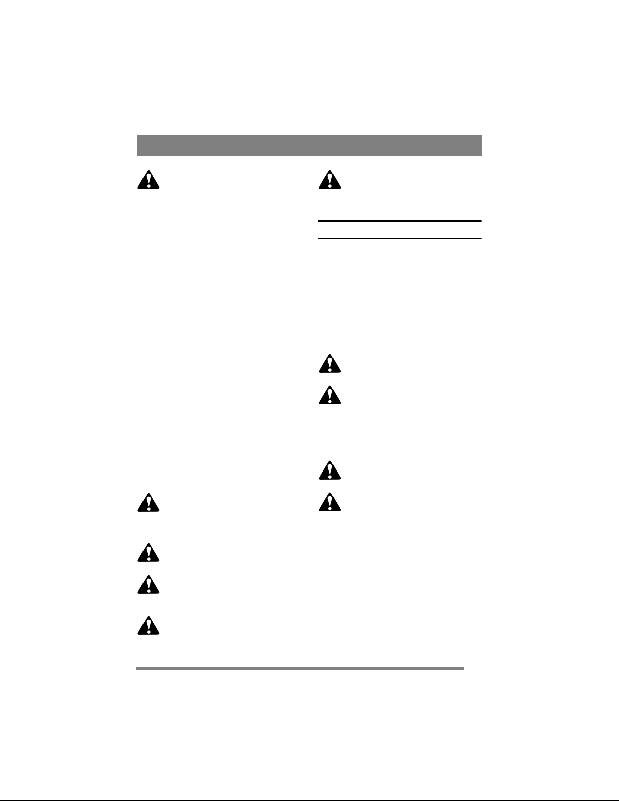
Dieses Symbol kennzeichnet eine WARNUNG. Ein Nichtbefolgen der Anweisungen kann Personen- und bzw. oder
Sachschäden nach sich ziehen.
Vor dem Start sind diese Bedienungsanleitung sowie die beigefügte Broschüre
“SICHERHEITSVORSCHRIFTEN"
aufmerksam durchzulesen.
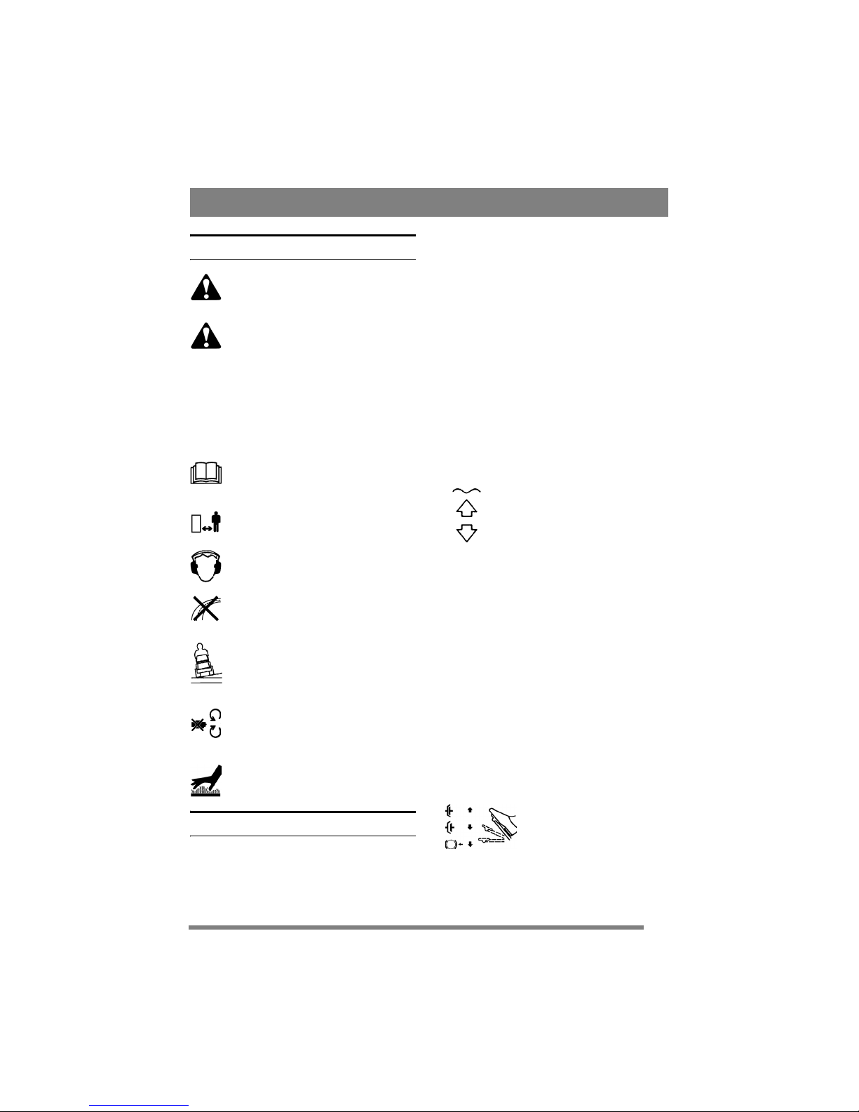
SYMBOLE
An der Maschine gibt es folgende Symbole, um
den Bediener darauf hinzuweisen, dass bei der Benutzung der Maschine Vorsicht und Aufmerksamkeit geboten sind.
Bedeutung der Symbole:
Warnung!
Lesen Sie vor der Benutzung der Maschine die Bedienungsanleitung und Sicherheitsvorschriften.
Warnung!
Achten Sie auf herausgeschleuderte Gegenstände. Stellen Sie sicher, dass sich
niemand im Gefahrenbereich des Mähers
aufhält.
Warnung!
Beim Mähen immer einen Gehörschutz
tragen.
Warnung!
Diese Maschine ist nicht für das Befahren
öffentlicher Straßen bestimmt.
Warnung!
Maschinen mit montierten Original-Zubehörteilen dürfen unabhängig von der
Richtung nur über Gefälle bis zu einem
Neigungswinkel von maximal 10° gefahren werden.
Warnung!
Quetschgefahr! Von der Mittellenkung einen Sicherheitsabstand einhalten.
Warnung!
Verbrennungsgefahr! Den Schalldämpfer
nicht berühren.
BEDIENELEMENTE UND
INSTRUMENTE
Punkte 1 - 19, siehe Abbildungen 1 - 6.
1. GERÄTEHEBER
(MF 860, MF 890 PRO)
Pedal zum Anheben frontmontierter Geräte in
Transportstellung.
Das Pedal bis zum Anschlag treten, um das Gerät
anzuheben. Danach das Pedal loslassen, der Geräteheber wird jetzt in angehobener Stellung arretiert.
Zum Absenken des Gerätes das Pedal erneut ganz
niedertreten, bis die Arretierung aufgehoben wird.
Dann das Pedal langsam wieder hochkommen lassen, bis sich der Geräteheber in Betriebsstellung
befindet.
2. HYDRAULISCHES ANHEBEN
(MF 890 PRO)
Hydraulisches Anheben frontseitig montierter Geräte in Transportstellung.
Um das Gerät anzuheben, drücken
Sie auf den hinteren Schalterteil.
Wenn die gewünschte Höhe erreicht
ist, lassen Sie den Schalter los.
Um das Gerät abzusenken, drücken
Sie auf den vorderen Schalterteil. Der
Schalter bleibt in dieser Position und
das Gerät wird bis in Fahrtposition
abgesenkt. In dieser Position kann
das Gerät den Geländekonturen folgen.
Diese Fahrposition mit dem Schalter in der vorderen Position wird für den normalen Betrieb empfohlen. Um den Geräteheber zu fixieren, stellen
Sie den Schalter in Normalposition.
Bitte beachten! Die hydraulische Hubvorrichtung muss sich in Fahrposition befinden, um die
Zapfwelle einkuppeln zu können.
3. BREMSE
Pedal zur Aktivierung des Bremssystems. Drei Positionen:
8
DEUTSCH
DE
1. Pedal in Ausgangsposition –
die Bremse ist nicht aktiviert.
2. Pedal zur Hälfte niedergetreten – der Antrieb ist ausgekuppelt. Die Bremse ist nicht
aktiviert.
Pedal vollkommen niedergetreten – der Antrieb ist ausgekuppelt. Die Bremse ist vollständig
aktiviert.
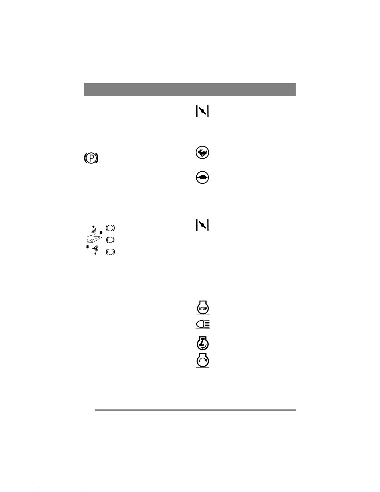
4. FESTSTELLBREMSE
Sperre, die das Bremspedal in niedergetretener
Stellung blockiert.
Das Bremspedal ganz niedertreten. Die
Bremssperre drücken und danach das
Bremspedal freigeben.
Die Feststellbremse wird durch einen Druck auf
das Bremspedal gelöst. Die federbelastete Sperre
gleitet dabei zur Seite.
Darauf achten, dass die Feststellbremse beim Fahren nicht aktiviert ist.
5. FAHRPEDAL
Pedal, das die stufenlose Kraftübertragung regelt.
1. Pedal mit der Fußspitze niederdrücken – die Maschine fährt
vorwärts.
2. Pedal unbetätigt – die Maschine steht still.
3. Pedal mit dem Hacken niederdrücken – die Maschine fährt
rückwärts.
Die Geschwindigkeit wird mit dem Fahrpedal reguliert. Je weiter es niedergedrückt wird, desto
schneller fährt die Maschine.
6. VERSTELLBARES LENKRAD
Die Höhe des Lenkrads kann stufenlos verstellt
werden. Den Einstellknopf an der Lenksäule lösen
und das Lenkrad auf die gewünschte Höhe einstellen. Danach wieder festdrehen.
Die Lenkradeinstellung nicht während der
Fahrt ändern.
7. GASHEBEL/CHOKE
Hebel zur Regulierung der Motordrehzahl sowie
als Choke beim Kaltstart des Motors. (Letzteres
gilt nicht für MF 880, MF 890 PRO, die einen separaten Choke haben, siehe Punkt 8).
1. MF 860: Choke – Starthilfe bei Kaltstarts. Der Chokehebel befindet sich ganz
vorn in der Aussparung. Die Maschine
sollte in dieser Hebelstellung nicht gefahren werden, statt dessen stellt man auf
Vollgas um, wenn der Motor warm ist
(siehe unten).
2. Vollgas – die Maschine sollte stets mit
Vollgas betrieben werden.
3. Leerlauf.
8. CHOKEHEBEL
(MF 880, MF 890 PRO)
Ziehregler für Choke bei Kaltstart.
1. Regler ganz herausgezogen – Chokedrosselklappe im Vergaser geschlossen.
Für Kaltstart.
2. Regler eingeschoben – Chokedrosselklappe offen. Für Warmstart und Normalbetrieb.
Niemals mit herausgezogenem Choke fahren,
wenn der Motor warm ist.
9. ZÜNDSCHLOSS/SCHEINWERFER
Das Zündschloss dient zum Anlassen und Abstellen des Motors. Es enthält auch einen Schalter für
den Scheinwerfer. Vier Stellungen:
1. Stoppstellung – der Motor ist kurzgeschlossen. Der Schlüssel kann abgezogen
werden.
2. Betriebsstellung – Scheinwerfer eingeschaltet.
3. Betriebsstellung – Scheinwerfer ausgeschaltet.

9
DEUTSCH
DE
4. Startstellung – wenn der Schlüssel in
die federbelastete Startstellung gedreht
wird, wird der elektrische Anlasser aktiviert. Wenn der Motor angesprungen ist,
den Schlüssel in Betriebsstellung 3 zurückgehen lassen.
Zum Einschalten des Scheinwerfers den Schlüssel
in Betriebsstellung 2 drehen.
10. MÄHANTRIEB (MF 860, MF 880)
Hebel zum Einkuppeln die Mähantrieb zum Antrieb frontmontierten Zubehörs. Zwei Stellungen:
1. Vordere Stellung – Mähantrieb ausgekuppelt.
2. Hintere Stellung – Mähantrieb eingekuppelt.
11. MÄHANTRIEB (MF 890 PRO)
Schalter zum Ein- und Auskuppeln der elektromagnetischen Mähantrieb zum Antrieb von frontseitig montiertem Zubehör. Zwei Stellungen:
1. Vorderen Schalterteil drücken – Mähantrieb wird eingekuppelt. Das Symbol
leuchtet auf.
2. Hinteren Schalterteil drücken – Mähantrieb wird ausgekuppelt.
12. DIFFERENTIALSPERRE
(MF 890 PRO)
Hebel zum Einkuppeln der Differentialsperre. Diese erhöht die Zugkraft, da die Hinterräder so gesperrt werden, dass beide Räder gleichzeitig
antreiben. Zwei Stellungen:
1. Vordere Stellung – Differentialsperre
nicht eingekuppelt. Normalbetrieb.
2. Hintere Stellung – Differentialsperre
eingekuppelt. Funktioniert sowohl beim
Vorwärts- als auch beim Rückwärtsfahren.
Die Differentialsperre ist sehr nützlich, wenn die
Hinterräder ungleichmäßig belastet sind, zum Beispiel bei maximalem Lenkradeinschlag, wenn das
innere Hinterrad am wenigsten belastet ist.
Auch beim Fahren im Winter auf glattem Untergrund verbessert die Differentialsperre den An-
trieb, wenn keine Schneeketten angewendet
werden.
Wenn die Differentialsperre eingekuppelt ist,
lässt sich die Maschine schwer lenken. Möglichst vermeiden, das Lenkrad zu drehen!
13. BETRIEBSSTUNDENZÄHLER
Zeigt die Betriebsstunden. Funktioniert nur bei
laufendem Motor.
14. TEMPOMAT
(MF 880, MF 890 PRO)
Stromschalter, der den Tempomat aktiviert. Mit
dem Tempomat lässt sich das Fahrpedal in gewünschter Stellung feststellen.
1. Das Fahrpedal niedertreten, bis die gewünschte Geschwindigkeit erreicht ist.
Dann auf den vorderen Teil des Schalters
drücken, um den Tempomat zu aktivieren.
Das Symbol leuchtet auf.
2. Den Tempomat durch Bremsen oder
Drücken auf den hinteren Teil des Schalters ausschalten.
15. SCHNITTHÖHENEINSTELLUNG
Die Maschine ist mit Hebeln für die Anwendung
von Mähwerken mit elektrischer Schnitthöheneinstellung ausgestattet (als Zubehör erhältlich).
Der Schalter dient zur stufenlosen Einstellung der Schnitthöhe.
Der Kontakt für den Anschluss des Mähwerks befindet sich auf der rechten Seite in Fahrtrichtung
vor dem Vorderrad (Abb. 3).
16. RECHEN (MF 890 PRO)
Die Maschine ist mit Bedienelementen für die Anwendung eines elektrisch heb- und senkbaren Rechens ausgestattet (als Zubehör erhältlich).
Der Schalter dient zum Heben und Senken
des Rechens.
Die Kabel für den Anschluss des Rechens befinden
sich hinten an der Maschine, links auf der Oberseite des Stoßdämpfers.
17. SANDSTREUER (MF 890 PRO)
Die Maschine ist mit Bedienelementen für die Anwendung eines elektrisch einzukuppelnden Sand-
10
DEUTSCH
DE
streuers ausgestattet (als Zubehör erhältlich).
Der Schalter dient zum Starten und Stoppen der Verteilerwalze.
Der Kontakt für den Anschluss des Sandstreuers
befindet sich hinten an der Maschine, links auf der
Oberseite des Stoßdämpfers.
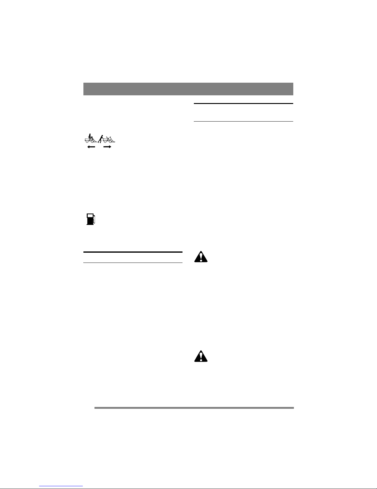
18. FREILAUFHEBEL
Hebel zum Auskuppeln der stufenlosen Kraftübertragung. Bietet die Möglichkeit, die Maschine von
Hand ohne Motorkraft zu schieben. Zwei Stellungen:
1. Hebel nach hinten – Kraftübertragung für Normalbetrieb
eingekuppelt.
2. Hebel nach vorn – Kraftübertragung ausgekuppelt. Die Maschine kann von Hand
geschoben werden.
Die Maschine darf nicht über längere Strecken
oder mit hoher Geschwindigkeit abgeschleppt
werden. Das Getriebe kann dabei beschädigt werden.
19. FÜLLSTANDANZEIGE/
TANKDECKEL
Tankdeckel mit eingebauter Füllstandanzeige, die den Füllstand im Benzintank
anzeigt (gilt für MF 880, MF 890 PRO).
Der Kraftstofftank fasst etwa 11,5 Liter.
ANWENDUNGSBEREICHE
Die Maschine darf nur für folgende Arbeiten und
mit dem angegebenen Originalzubehör eingesetzt
werden:
1. Rasen mähen
Mit Mähwerk AMM 842, AME 842,
AMM 848, AME 848, AMM 842 HD,
AME 842 HD oder Schlägelmähwerk
ASM 836.
2. Schnee räumen
Mit Schneeräumschild ASS 847. Schneeketten
ASK 416, ASK 817 und Rahmengewichte
AMG 175 werden empfohlen.
Die Zugvorrichtung darf mit einer senkrechten
Kraft von höchstens 100 N belastet werden.
Die Schubkraft von angehängtem Zubehör darf die
Zugvorrichtung mit höchstens 500 N belasten.
Bitte beachten! Vor der Anwendung eines Transportanhängers mit der Versicherung sprechen.
Bitte beachten! Diese Maschine ist nicht zum Befahren öffentlicher Straßen bestimmt.
START UND BETRIEB
MOTORHAUBE
Für Service- und Wartungsarbeiten an Motor und
Batterie ist die Motorhaube abzunehmen. Demontage:
1. Schrauben Sie Tankdeckel/Benzinmesser ab.
2. Ziehen Sie die Gummibefestigung an der Haubenvorderseite nach oben (Abb. 7).
3. Heben Sie die Motorhaube vorsichtig ab
(Abb. 8).
Montage:
1. Positionieren Sie die Motorhaube auf beiden
Seiten über den Zapfen.
2. Passen Sie die Zapfen an der Haubenhinterseite
in die beiden Aussparungen ein (Abb. 9).
3. Fixieren Sie die Haube an der Vorderseite mit
der Gummibefestigung (Abb. 7).
4. Schrauben Sie Tankdeckel/Benzinmesser wieder auf.
Die Maschine darf nicht benutzt werden, wenn die Motorhaube demontiert
ist. Es besteht Verbrennungs- und
Quetschgefahr.
BENZINTANK FÜLLEN
Immer reines bleifreies Benzin tanken. 2-Takt-Mischungen dürfen nicht verwendet werden.
Bitte beachten! Bleifreies Normalbenzin ist eine
“Frischware", deshalb nicht mehr Benzin kaufen,
als in 30 Tagen verbraucht wird.
Auch umweltfreundliches Benzin, sog. Alkylatbenzin, ist bestens geeignet. Diese Benzinsorte ist
weniger umwelt- und gesundheitsschädlich als
herkömmliches Benzin.
Benzin ist sehr feuergefährlich. Der
Kraftstoff ist ausschließlich in speziell
für diesen Zweck hergestellten Kanis-
12V
11
DEUTSCH
DE
tern aufzubewahren.
Benzin darf nur im Freien aufgefüllt
werden, Rauchen ist dabei zu unterlassen. Den Kraftstoff vor dem Anlassen
des Motors einfüllen. Den Tankverschluss nicht abnehmen und kein Benzin einfüllen, wenn der Motor in
Betrieb oder noch warm ist.
Den Benzintank nie ganz voll füllen. Den Einfüllstutzen sowie die oberen 1-2 cm des Tanks freilassen, damit sich das Benzin bei Erwärmung
ausdehnen kann, ohne überzulaufen (Abb. 17).
ÖLSTAND - MOTORÖL
Bei Lieferung ist das Kurbelgehäuse mit Öl des
Typs SAE 30 gefüllt.
Den Ölstand vor jeder Anwendung der Maschine kontrollieren. Dabei sollte die Maschine auf
einer ebenen Unterlage stehen.
Rund um den Ölmessstab sauberwischen.
Stab lösen und herausziehen. Ölmessstab
abwischen. Danach ganz einschieben und
festschrauben.
Dann wieder losschrauben und herausziehen. Ölstand ablesen. Wenn er unter der Markierung
“FULL" liegt, bis zu dieser Markierung Öl nachfüllen (Abb. 10).
ÖLSTAND - GETRIEBEÖL
Das Getriebe ist bei der Lieferung mit Öl des Typs
SAE 10W-40 gefüllt.
Den Ölstand vor jeder Anwendung der Maschine kontrollieren. Dabei sollte die Maschine auf
einer ebenen Unterlage stehen.
Den Ölstand am Behälter (Abb. 18) ablesen. Das
Niveau soll zwischen "MAX" und "MIN" liegen.
Bei Bedarf Öl nachfüllen. Dafür Öl SAE 10W-40
(20W-50) verwenden.
SICHERHEITSSYSTEM
Diese Maschine ist mit einem Sicherheitssystem
ausgestattet, das aus folgenden Teilen besteht:
- ein Schalter am Bremspedal.
- ein Schalter im Sitz (MF 860) bzw. in der Sitzkonsole (MF 880, MF 890 PRO).
- ein Schalter am Zuschalthebel für die Zapfwelle.
Der Start der Maschine setzt folgendes voraus:
- Bremspedal niedergetreten.
- Fahrer sitzt auf dem Sitz.
- Zuschalthebel für die Zapfwelle in vorderer
Stellung (= Zapfwelle freigekuppelt).
Vor jedem Einsatz ist die Funktion des
Sicherheitssystems unbedingt zu überprüfen!
Bei laufendem Motor und auf dem Sitz sitzend die
Funktionen folgendermaßen kontrollieren:
- Fahrpedal niedertreten, so dass sich die Maschine bewegt, dann Fahrpedal freigeben - Maschine muss stehenbleiben.
- Fahrpedal niedertreten, so dass sich die Maschine bewegt, dann Tempomat einschalten, vom
Sitz erheben - die Maschine muss stehenbleiben
(MF 880, MF 890 PRO).
- Fahrpedal niedertreten, so dass sich die Maschine bewegt, dann Fahrtregler einschalten, Bremspedal niedertreten - die Maschine muss
stehenbleiben (MF 880, MF 890 PRO).
- Zapfwelle einschalten, vom Sitz erheben - der
Motor muss ausgehen.
Wenn das Sicherheitssystem nicht einwandfrei funktioniert, darf die Maschine nicht benutzt werden! Maschine zur
Kontrolle in eine autorisierte Servicewerkstatt bringen.
START
1. Benzinhahn öffnen (Abb. 11).
2. Kontrollieren, ob das Zündkerzenkabel ange-
schlossen ist.
3. Kontrollieren, ob die Zapfwelle ausgekuppelt
ist.
4. Den Fuß nicht auf das Fahrpedal setzen.
5a. MF 860:
Kaltstart – den Fahrpedal in Chokestellung vorschieben. Warmstart – Gashebel auf Vollgas stellen (ca. 1 cm unter der Chokestellung).
5b. MF 880, MF 890 PRO:
Gashebel auf Vollgas stellen. Kaltstart – den
Choke ganz herausziehen. Warmstart – Choke
nicht herausziehen.
6. Bremspedal ganz niedertreten.
7. Zündschlüssel drehen und Motor anlassen.
8a. MF 860:
Wenn der Motor läuft, den Gashebel nach und
nach auf Vollgas schieben, falls vorher der Choke-

12
DEUTSCH
DE
regler betätigt worden ist.
8b. MF 880, MF 890 PRO:
Wenn der Motor läuft, den Chokeregler nach und
nach einschieben, falls er vorher betätigt worden
ist.
9. Bei Kaltstart die Maschine nicht unmittelbar
nach dem Start belasten, sondern den Motor erst
einige Minuten lang warmlaufen lassen. Das Öl
muss erst warm werden.
Beim Fahrbetrieb den Motor immer mit Vollgas
laufen lassen.
STOPP
Zapfwelle auskuppeln. Feststellbremse betätigen.
Den Motor 1 bis 2 Minuten im Leerlauf laufen las-
sen. Motor durch Drehen des Zündschlüssels ausschalten.
Den Benzinhahn schließen. Dies ist besonders
wichtig, wenn die Maschine z. B. auf einem Anhänger transportiert werden soll.
Wird der Rasenmäher ohne Aufsicht
stehen gelassen, ist das Zündkerzenkabel von der Zündkerze abzuziehen.
Auch den Zündschlüssel abziehen.
Der Motor kann unmittelbar nach dem
Ausschalten sehr heiß sein. Schalldämpfer, Zylinder oder Kühlrippen
nicht berühren. Dies kann zu Verbrennungen führen.
LENKHILFE (MF 890 PRO)
Eingebaute Funktion, die das Lenken erleichtert.
Das Drehen des Lenkrads erfordert weniger Kraftaufwand. Beim Drehen des Lenkrads wird die Wirkung durch einen Lenkservostaten verstärkt.
Der Unterschied zu einer herkömmlichen Servolenkung (z. B. in einem Auto) besteht darin, dass
diese Lenkhilfe eine begrenzte Leistung hat. So
weist sie bestimmte Eigenschaften auf, die als negativ aufgefasst werden können:
- bei niedrigen Motordrehzahlen oder in Situationen, in denen extra starke Lenkkraft erforderlich ist, kann die Lenkung als “stockend"
empfunden werden.
- beim Lenken sollte die Maschine immer in Bewegung sein. Wenn sie still steht und das Zubehör in Arbeitsstellung abgesenkt ist, sollte
vermieden werden, am Lenkrad zu drehen.
Die Lenkhilfe ist dafür konzipiert, das Lenken bei
normaler Betriebsfahrgeschwindigkeit zu erleichtern. Unter diesen Bedingungen weist sie große
Vorteile auf.
Die Lenkhilfe funktioniert auch, wenn der Motor
nicht läuft. Das Fahren von Kurven ist jedoch
schwerer, wenn die Maschine geschoben wird.
FAHRTI PPS
Beim Fahren an Hängen sorgfältig darauf achten,
dass sich im Motor genug Öl befindet (Ölstand
“FULL").
Beim Fahren an Abhängen ist besondere Vorsicht geboten. Keine abrupten
Starts oder Stopps beim Fahren an Abhängen. Niemals quer zum Hang, sondern immer aufwärts oder abwärts
fahren. Von oben nach unten und von
unten nach oben fahren.
Mit montiertem Originalzubehör darf
die Maschine ungeachtet der Fahrrichtung im Verhältnis zum Abhang mit
maximal 10° Neigung gefahren werden.
An Hängen und in scharfen Kurven die
Geschwindigkeit herabsetzen, um zu
verhindern, dass die Maschine umkippt
oder außer Kontrolle gerät.
Bei Vollgas und höchstem Gang keine
engen Kurven fahren. Die Maschine
kann umkippen.
Hände und Finger von Knickgelenk
und Sitzkonsole fernhalten. Quetschgefahr! Niemals ohne Motorhaube fahren.
SERVICE UND WARTUNG
SERVICEPROGRAMM
Wir empfehlen, den Service jeweils in einer autorisierten Servicewerkstatt ausführen zu lassen.
Dann ist sichergestellt, dass die Arbeit von kompetentem Personal und unter Verwendung von Originalersatzteilen ausgeführt wird.
VORBEREITUNG
Wenn nichts anderes angegeben ist, sind Serviceund Wartungsmaßnahmen bei still stehender Maschine und abgestelltem Motor durchzuführen.
13
DEUTSCH
DE
Ziehen Sie immer die Feststellbremse
an, um ein Wegrollen der Maschine
auszuschließen.
Halten Sie den Motor an, ziehen Sie das
Zündkerzenkabel von der Zündkerze
ab und erden Sie es, um ein unbeabsichtigtes Starten des Motors zu verhindern. Lösen Sie das Minuskabel von der
Batterie.
REINIGUNG
Zur Verringerung der Brandgefahr
Motor, Schalldämpfer, Batterie und
Kraftstofftank von Gras, Laub und Öl
frei halten.
Zur Verringerung der Brandgefahr die
Maschine regelmäßig auf Öl- und/oder
Kraftstoffaustritt kontrollieren.
Bei der Verwendung von Hochdruckreinigern den
Strahl nicht direkt auf das Getriebe richten.
Den Motor nicht mit Wasser abspülen. Zur Reinigung eine Bürste oder Druckluft benutzen.
MOTORÖL
Das Motoröl erstmalig nach 5 Betriebsstunden
wechseln, danach alle 50 Betriebsstunden oder
einmal pro Saison. Den Ölwechsel vornehmen, solange der Motor warm ist.
Nur Qualitätsöl verwenden (Serviceklasse SF, SG
oder SH).
Bei extrem hoher Belastung oder bei hoher Umgebungstemperatur das Öl häufiger wechseln, alle 25
Betriebsstunden oder mindestens einmal pro Saison.
Das Motoröl kann sehr heiß sein, wenn
es direkt nach der Benutzung der Maschine abgelassen wird. Daher den Motor vor dem Ablassen des Öls einige
Minuten abkühlen lassen.
1. Ölablassrohr (Metall):
Die Ölablassschraube am Rohrende herausdrehen.
Das Öl in einem Gefäß auffangen. Entsorgen
Sie das Altöl und die alten Filter vorschriftsmäßig bei Altöl-Annahmestellen. Vorsicht, kein Öl
auf die Keilriemen verschütten.
2. Die Ölablassschraube wieder eindrehen. Kon-
trollieren, ob Faserdichtung und O-Ring in der
Schraube sich in einwandfreiem Zustand befinden
und an ihrem Platz liegen.
3. Den Ölmessstab herausnehmen und neues Öl
einfüllen.
Ölmenge: 1,4 Liter
Ölsorte Sommer (> 4° C): SAE-30
(SAE 10W-30 kann auch verwendet werden. Bei
dieser Sorte kann jedoch der Verbrauch etwas ansteigen. Deshalb ist bei Verwendung dieser Ölsorte der Ölstand etwas häufiger zu kontrollieren).
Ölsorte Winter (< 4° C): SAE 5W-30
(falls dieses Öl nicht erhältlich ist, SAE 10W-30
verwenden).
Dem Öl keine Zusätze beimischen.
Nicht zuviel Öl einfüllen. Dies könnte den Motor
überhitzen.
Nach dem Einfüllen von Öl den Motor starten und
30 Sekunden lang im Leerlauf laufen lassen. Motor ausstellen. 30 Sekunden warten und den Ölstand kontrollieren.
Die Maschine auf undichte Stellen prüfen. Bei Bedarf bis zur Markierung “FULL" Öl nachfüllen.
ÖLFILTER - MOTOR
(MF 880, MF 890 PRO)
Den Ölfilter alle 100 Betriebsstunden oder einmal
pro Saison auswechseln.
Bevor der neue Filter festgeschraubt wird, ist die
Filterdichtung mit Motoröl einzuschmieren.
Den Filter von Hand festschrauben, bis die Filterdichtung den Filtersitz berührt. Dann noch eine
weitere ½ bis ¾ Umdrehung anziehen (Abb. 20).
Den Motor starten und im Leerlauf laufen lassen,
um auf eventuelle Lecks zu kontrollieren. Motor
ausstellen. Ölstand prüfen. Bei Bedarf bis zur Markierung “FULL" Öl nachfüllen.
LUFTFILTER - MOTOR
Den Vorfilter alle 3 Monate oder alle 25 Betriebsstunden reinigen, je nachdem, was zuerst eintrifft.
Den Papierfilter einmal pro Jahr oder alle 100 Betriebsstunden reinigen, je nachdem, was zuerst eintrifft.
ACHTUNG! Wenn die Maschine unter staubigen
Bedingungen eingesetzt wird, beide Filter häufiger
reinigen.
14
DEUTSCH
DE
1. Den Luftfilterdeckel entfernen (Abb. 12 - 13).
2. Papierfilter und Vorfilter (Schaumstofffilter)
demontieren. Vorsichtig arbeiten, damit kein
Schmutz in den Vergaser gelangt. Das Luftfiltergehäuse reinigen.
3. MF 880
Den Vorfilter mit flüssigem Spülmittel und Wasser auswaschen. Filter ausdrücken. Etwas Öl auf
den Filter gießen und einmassieren.
4a. MF 880, MF 890 PRO
Papierfilter folgendermaßen reinigen: Filter leicht
gegen eine ebene Fläche klopfen. Wenn der Papierfilter sehr schmutzig ist, sollte er ausgewechselt werden.
4b. MF 860
Neuen Vorfilter und Patrone fest in die Grundplatte legen.
5. Den Luftfilter in umgekehrter Reihenfolge wie-
der zusammensetzen.
Zur Reinigung des Papierfilters dürfen keine Lö-
sungsmittel wie z. B. Petroleum verwendet werden. Diese Lösungsmittel zerstören den Filter.
Zur Reinigung des Papierfilters keine Druckluft
benutzen. Der Papierfilter darf nicht eingeölt werden.
ZÜNDKERZE
Zur Kontrolle des Zündkerzenfunkens grundsätzlich einen Briggs & Stratton Funkentester verwenden (Abb. 14).
Die Zündkerze alle 100 Betriebsstunden oder einmal pro Saison austauschen. Hierzu befindet sich
im Zubehörbeutel ein Zündkerzenschlüssel A und
ein Drehstift B.
Der Motorhersteller empfiehlt:
Champion RC12YC.
Korrekter Elektrodenabstand: 0,75 mm.
KÜHLLUFTEINLASS - MOTOR
Der Motor ist luftgekühlt. Verstopfungen im Kühlsystem schaden dem Motor. Den Motor alle 100
Betriebsstunden oder mindestens einmal pro Jahr
reinigen.
Das Gebläsegehäuse abnehmen. Die Kühlflansche
des Zylinders, das Gebläse und das rotierende
Schutzgitter. Wenn sehr trockenes Gras gemäht
wird, häufiger reinigen.
BATTERIE
Bei der Batterie handelt es sich um ein ventilgesteuertes Modell mit 12 V Nennspannung. Die
Batterie ist komplett wartungsfrei. Es ist weder
eine Messung des Elektrolytfüllstands noch ein
Nachfüllen erforderlich.
Bei Lieferung befindet sich die Batterie im Zubehörkarton.
Vor ihrer ersten Verwendung ist die
Batterie vollständig aufzuladen. Sie ist
darüber hinaus stets in voll geladenem
Zustand zu lagern. Wenn die Batterie
völlig entladen gelagert wird, kann sie
bleibende Schäden davontragen.
Wenn die Maschine für einen längeren Zeitraum
nicht verwendet wird (mehr als 1 Monat), muss die
Batterie geladen und anschließend in isoliertem
Zustand an einem kühlen und sicheren Ort verwahrt werden. Laden Sie die Batterie vor einem erneuten Einsatz vollständig auf.
Die Batterie kann auf zwei Arten geladen werden:
1. Man kann den Motor zum Aufladen der Batterie
nutzen. Dabei ist es sehr wichtig, vor allem
beim ersten Start und wenn die Maschine längere Zeit nicht benutzt wurde, dass man den Motor mindestens 45 Minuten lang
ununterbrochen laufen lässt.
2. Über ein Batterieladegerät. Es muss ein Ladegerät mit einer konstanten Spannung sein. Bei
Verwendung eines Standardladegeräts (für
Säurebatterien) kann die Batterie beschädigt
werden.
Die Batteriepole dürfen nicht kurzgeschlossen werden. Dadurch kann es zu
Funkenbildung und Bränden kommen.
Tragen Sie keinen Metallschmuck, der
mit den Batteriepolen in Kontakt kommen kann.
Bei Beschädigungen von Batteriegehäuse, Abdeckung, Polen oder Eingriffen in die Ventilabdeckleisten ist die
Batterie zu wechseln.
Oxidierte Batteriepole müssen gereinigt werden.
Dazu eine Stahlbürste verwenden und die Pole mit
Fett einschmieren.
SCHMIERUNG
Das Mittelgelenk der Maschine hat vier Schmier-

15
DEUTSCH
DE
nippel, die alle 25 Betriebsstunden mit Universalfett zu schmieren sind (Abb. 15).
Anm.: Der vierte Schmiernippel ist auf der Abbildung nicht zu sehen. Er befindet sich auf der Unterseite am vorderen Lager der Gelenkwelle.
Die Lenkkette ein paarmal pro Saison mit Kettenspray schmieren.
Die vordere Radnabe hat Schmiernippel, die alle
50 Betriebsstunden zu schmieren sind (Abb. 19).
Alle Kunststofflager einige Mal pro Saison mit
Universalfett schmieren.
Die Spannarmgelenke einige Male pro Saison mit
Motoröl schmieren.
Einige Male pro Saison etwas Motoröl auf beide
Enden der Seilzüge tropfen.
Das hydrostatische Getriebe ist bei Lieferung mit
Öl (10W-40) gefüllt. Wenn es nicht geöffnet wird
(was nur durch einen Fachmann erfolgen darf) und
wenn kein Leck vorhanden ist, braucht normalerweise kein Öl nachgefüllt zu werden. Das Getriebeöl muss normalerweise nicht gewechselt
werden.
LENKSEILZÜGE (MF 860, MF 880)
Die Lenkseilzüge erstmalig nach 2 – 3 Betriebsstunden nachstellen, dann alle 25 Betriebsstunden.
Die Lenkung auf “Geradeausfahren" einstellen.
Die Lenkseilzüge durch Einschrauben der Muttern
auf der Unterseite des Mittelgelenks (Abb. 16)
spannen. Die Schraubenden der Lenkseilzüge bei
der Einstellung festhalten, damit sich die Seilzüge
nicht drehen können. Hierzu einen Maulschlüssel
oder Stellschlüssel an den Schraubenenden verwenden. So lange nachstellen, bis kein Spiel mehr
vorhanden ist.
Beide Muttern gleich anziehen, das Lenkrad darf
sich nicht bewegen.
Nach dem Nachstellen das Lenkrad in beide Richtungen bis zum Anschlag drehen. Kontrollieren,
dass die Kette sich nicht in der Seilrolle und die
Seilzüge sich nicht im Lenkungsritzel verfangen.
Die Seilzüge nicht zu stark spannen. Die Lenkung
ist dann schwergängig und der Verschleiß der Seilzüge nimmt zu.
LENKKETTEN (MF 890 PRO)
Die Lenkketten erstmalig nach 2 – 3 Betriebsstun-
den nachstellen, dann alle 50 Betriebsstunden.
Die Lenkung auf “Geradeausfahren" einstellen.
Die Lenkketten durch Einschrauben der Muttern
auf der Unterseite des Mittelgelenks (Abb. 16)
spannen. So lange nachstellen, bis kein Spiel mehr
vorhanden ist.
Beide Muttern gleich anziehen, das Lenkrad darf
sich nicht bewegen.
Die Lenkketten nicht zu stark spannen. Die Lenkung ist dann schwergängig und der Verschleiß
der Ketten nimmt zu.
16
ENGLISH
EN
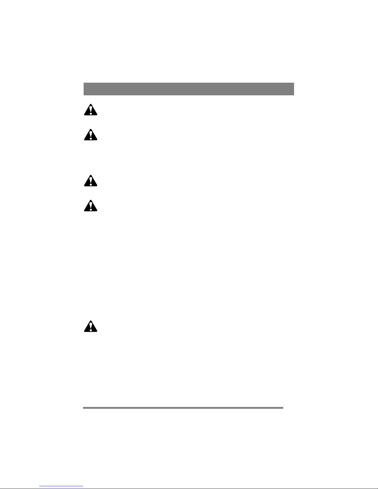
GENERAL
This symbol indicates WARNING. Personal injury and/or damage to property
may result if the instructions are not
followed carefully.
You must read these instructions for
use and the accompanying pamphlet
“SAFETY INSTRUCTIONS” carefully, before starting up the machine.
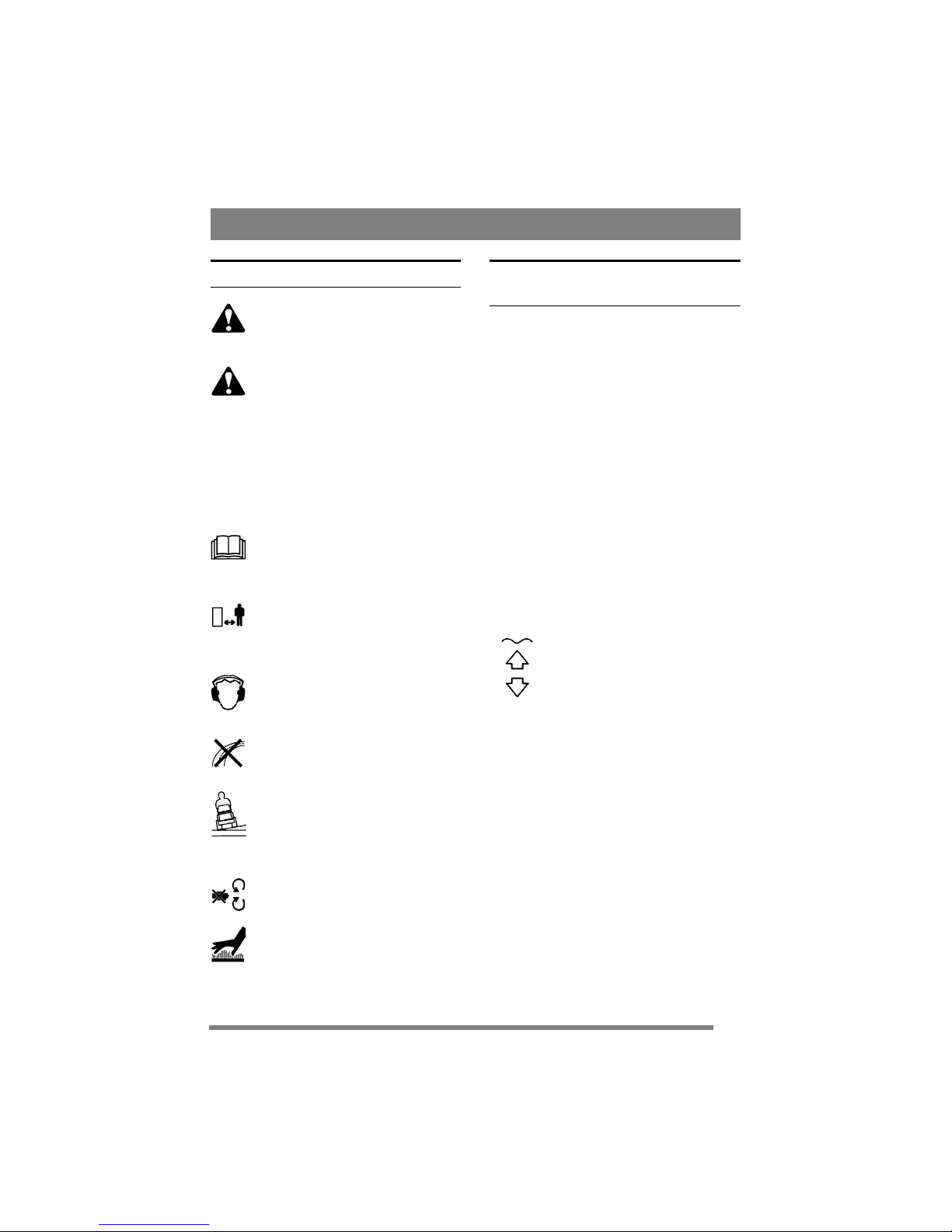
SYMBOLS
The following symbols appear on the machine.
They are there to remind you of the care and attention required in use.
This is what the symbols mean:
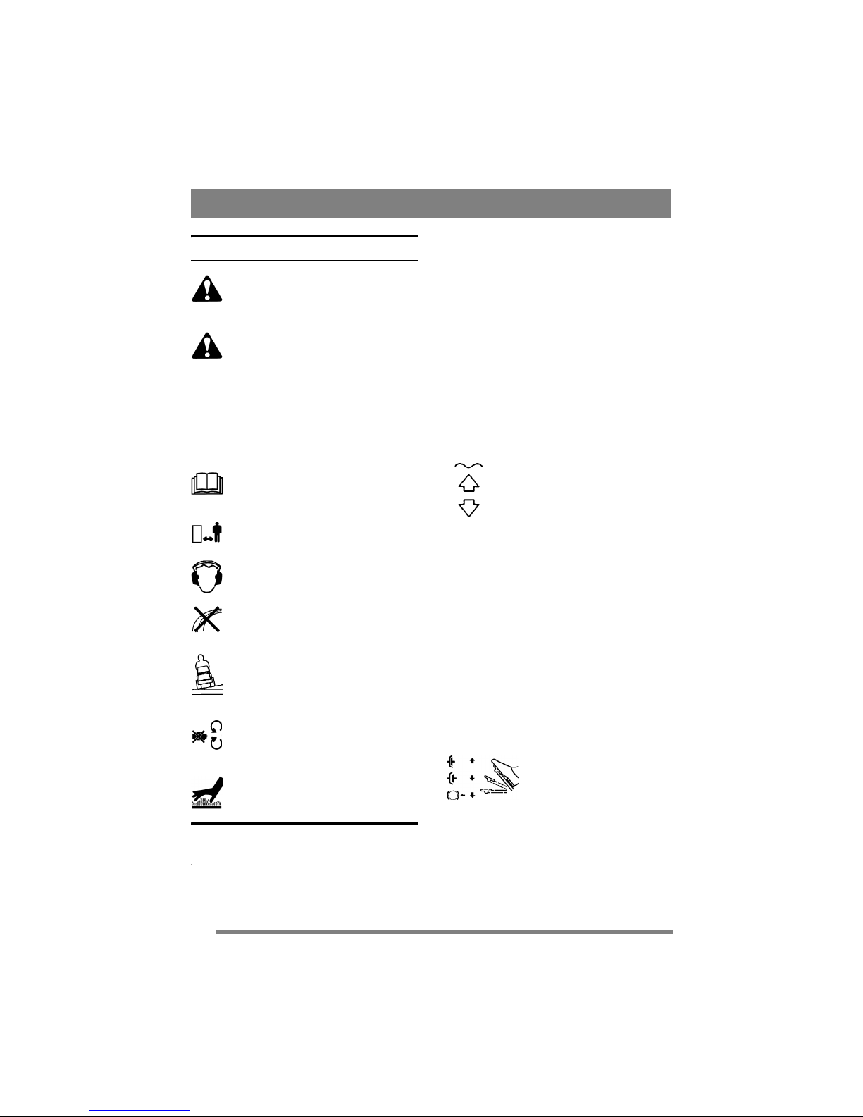
Warning!
Read the instruction manual and the safety
manual before using the machine.
Warning!
Watch out for discarded objects. Keep onlookers away.
Warning!
Always wear hearing protectors.
Warning!
This machine is not designed to be driven
on public roads.
Warning!
The machine, equipped with original accessories, must not be driven in any direction on slopes with a gradient greater than
10º.
Warning!
Risk of crushing injuries. Keep hands and
feet well away from the articulated steering joint.
Warning!
Risk of burn injuries. Do not touch the silencer/catalytic converter.
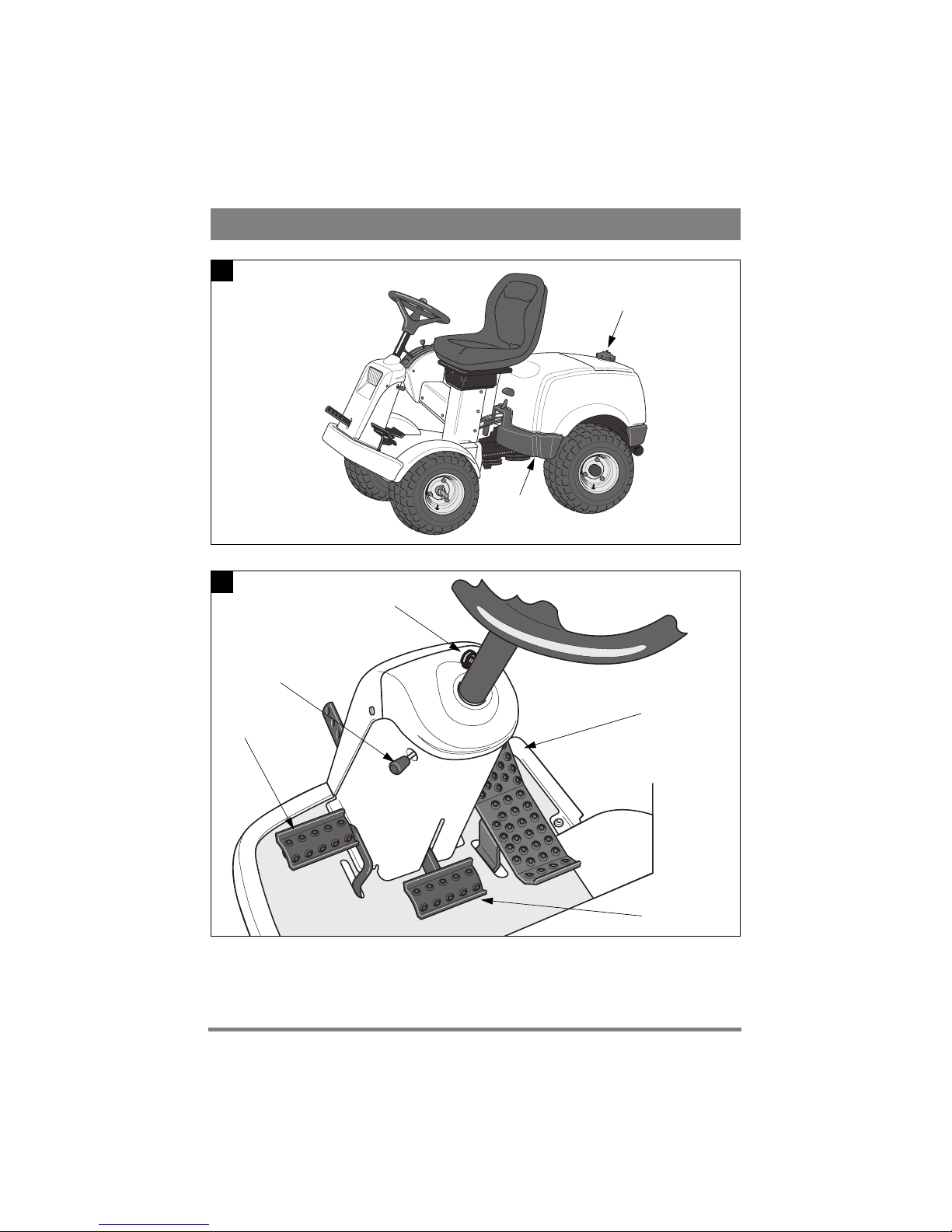
CONTROLS AND
INSTRUMENTS
Items 1 - 19, see figures 1 - 6.
1. IMPLEMENT LIFTER
(MF 860, MF 880)
A pedal for raising front-mounted implement to
the transport position.
To lift up the implement, press the pedal down as
far as it will go. Then release the pedal, the implement lifter is now locked in the raised position.
To lower the implement, press the pedal down so
that the lock is released. Lower the implement lifter to the working position by slowly lifting your
foot from the pedal.
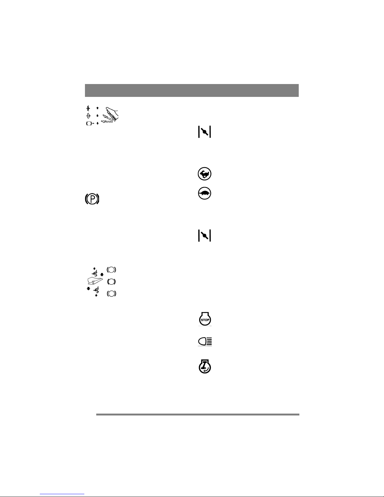
2. HYDRAULIC LIFTER (MF 890 PRO)
Hydraulic implement lifter for raising frontmounted implements to the transport position.
To raise the implement, press the rear
part of the switch. Release the switch
in the required position.
To lower the accessory, press the
front part of the switch. The switch
stays in the pressed position and the
implement lifter is lowered until it
reaches a floating position. This
means that the implement can follow
the contours of the ground.
The floating position, with the switch in the tilted
forward position, is recommended for normal use.
To secure the implement lifter, place the switch in
neutral.
NOTE! The hydraulic implement lifter must be
in floating position in order for the power takeoff to be connected.
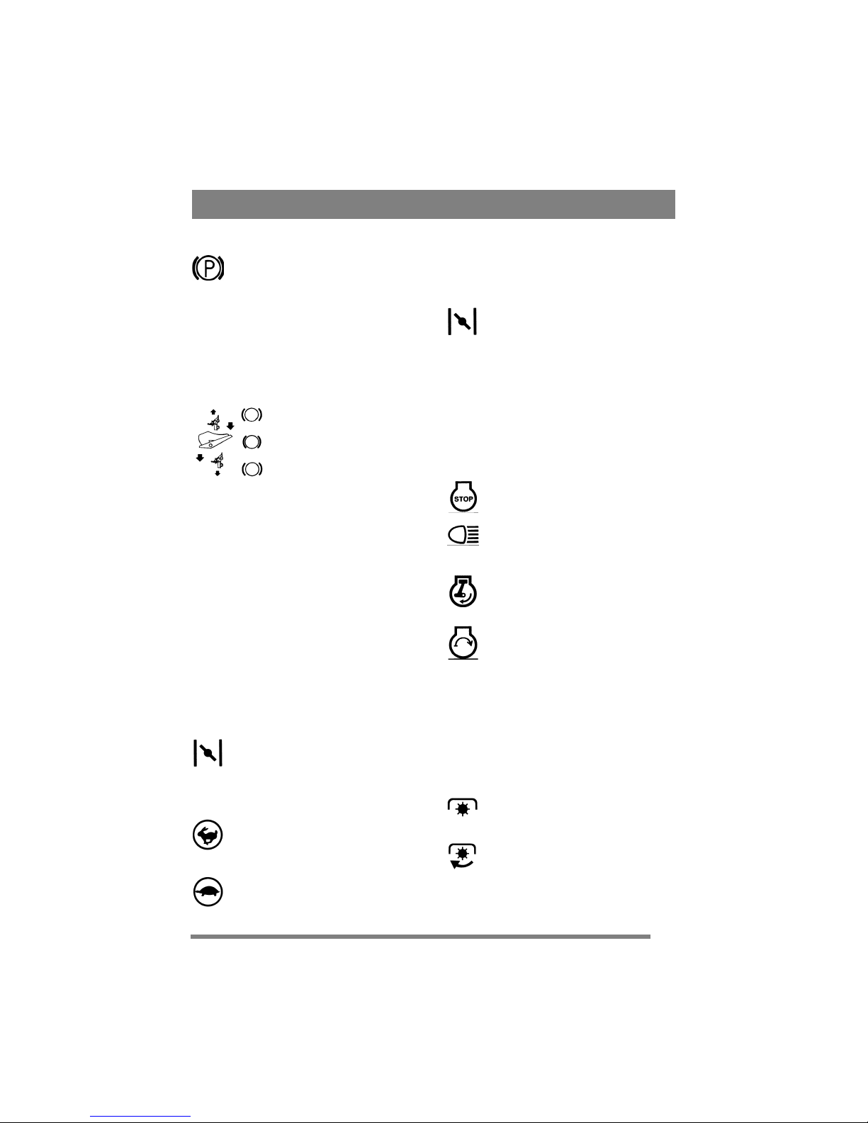
3. SERVICE BRAKE
A pedal that acts on the machine’s braking system.
There are 3 positions:
1. Pedal released – service brake
not activated.
2. Pedal depressed halfway –
forward drive disengaged. Service brake not activated.
3. Pedal fully depressed – forward drive disengaged. Service
brake fully activated.
4. PARKING BRAKE
An inhibitor that can lock the brake pedal in the de-
17
ENGLISH
EN
pressed position.
Depress the brake pedal fully. Depress the
inhibitor and then release the brake pedal.
The parking brake is released by pressing
the brake pedal. The spring-loaded inhibitor slides
to one side.
Make sure that the parking brake is released when
operating the machine.
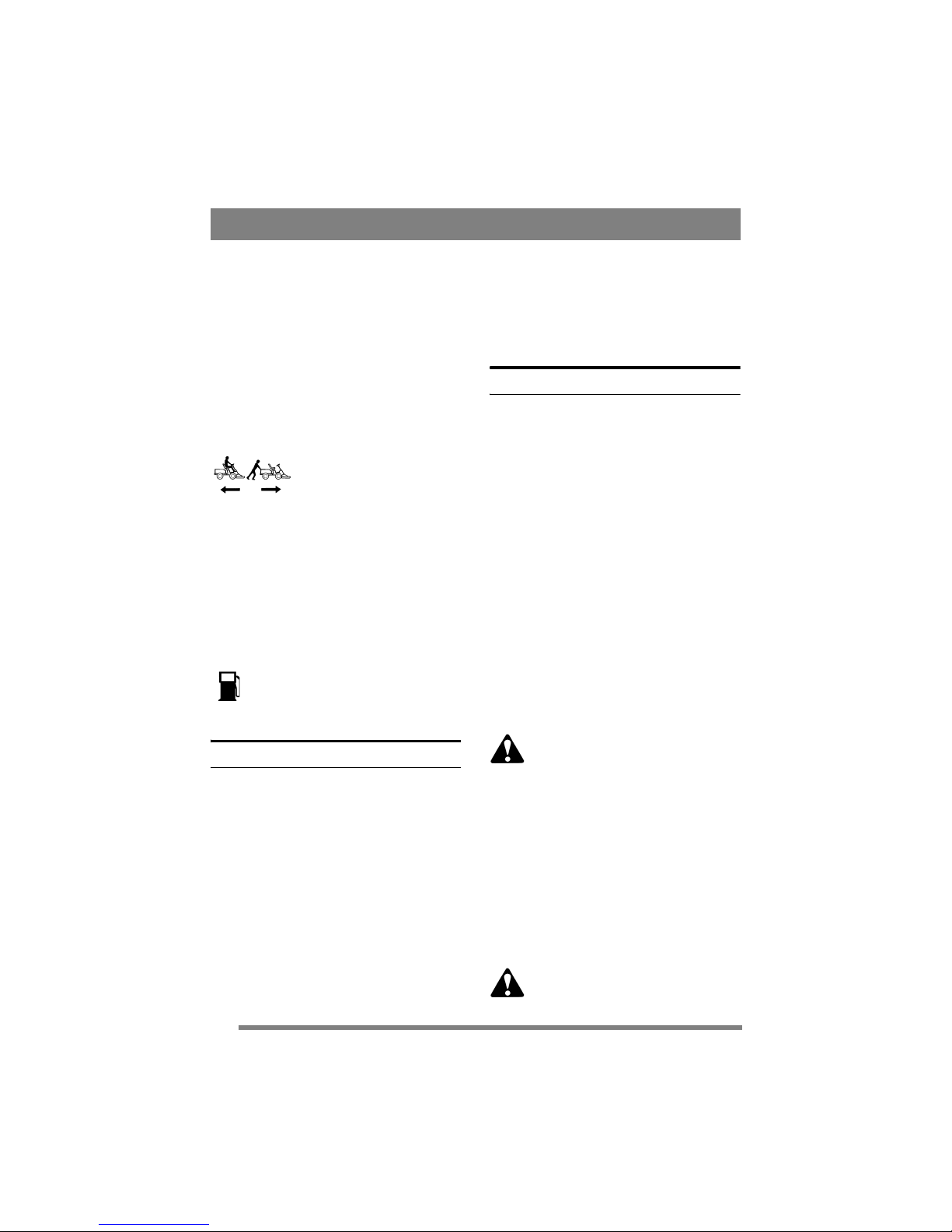
5. DRIVE PEDAL
A pedal that activates the variable transmission.
1. Depress the pedal with the
ball of your foot – the machine
moves forwards.
2. No load on the pedal – the machine is stationary.
3. Depress the pedal with your
heel – the machine reverses.
The drive pedal regulates the speed. The more
pressure applied, the faster the machine will move.
6. ADJUSTABLE STEERING WHEEL
The height of the steering wheel is infinitely adjustable. Undo the adjustment knob on the steering
column and raise or lower the steering wheel to the
desired position. Tighten.
Do not adjust the steering wheel during operation.
7. THROTTLE/CHOKE CONTROL
A control for setting the engine speed and to choke
the engine when starting from cold. (The latter
does not apply to MF 880, MF 890 PRO which
have separate choke control – see item 8).
1. MF 860: Choke – for starting a cold en-
gine. The choke is located in top of
groove. Avoid operating the machine in
this position, taking care to move the con-
trol to full throttle (see below) when the
engine is warm.
2. Full throttle – when the machine is in
operation, full throttle should always be
used.
3. Idling.
8. CHOKE CONTROL
(MF 880, MF 890 PRO)
A pull-type control to choke the engine when starting from cold.
1. Control fully pulled out – choke valve
in carburettor closed. For starting cold engine.
2. Control pushed in – choke valve open.
For starting warm engine and when operating the machine.
Never operate the machine with the choke
pulled out when the engine is warm.
9. IGNITION LOCK/SPOTLIGHT
Ignition lock used for starting/stopping the engine.
Also includes switch for spotlight. Four positions:
1. Stop position – the engine is shortcircuited. The key can be removed.
2. Operating position – spotlight activated.
3. Operating position – spotlight not activated.
4. Start position – the electric start motor
is activated when the key is turned to the
spring-loaded start position. Once the engine has started, let the key return to operating position 3.
To turn on the spotlight, turn the key to position 2.
10. POWER TAKE-OFF
(MF 860, MF 880)
A lever for engaging and disengaging the power
take-off for operating front-mounted accessories.
Two positions:
1. Lever in forward position – power takeoff disengaged.
2. Lever in backward position - power
take-off engaged.

18
ENGLISH
EN
11. POWER TAKE-OFF (MF 890 PRO)
Switch for engaging/disengaging the electromagnetic power take-off for operating front-mounted
accessories. Two positions:
1. Press the front part of the switch – the
power take-off is engaged. The symbol
will light up.
2. Press the rear part of the switch – the
power take-off is disengaged.
12. DIFFERENTIAL INHIBITOR
(MF 890 PRO)
Lever for engaging the differential inhibitor. This
improves the towing capacity by locking the rear
wheels so that both wheels drive simultaneously.
Two positions:
1. Forward position – the differential in-
hibitor is not engaged. For normal opera-
tion.
2. Lever in backward position - differen-
tial inhibitor engaged. Works for both for-
ward and reverse drive.
The differential inhibitor is of greatest use when
the rear wheels are unevenly loaded. For example
when turning sharp corners where the inner rear
wheel bears a lesser load.
When driving during the winter on slippery surfaces, the drive capacity is improved if snow chains
are not used.
When the differential inhibitor is engaged, the
steering is heavy. Avoid turning the steering
wheel!
13. HOUR COUNTER
Indicates the number of working hours. Only
works when the engine is running.
14. CRUISE CONTROL
(MF 880, MF 890 PRO)
A switch for activating the cruise control. The
cruise control allows the drive pedal to be locked
in the desired position.
1. Press down the drive pedal until the desired speed is obtained. Then press the
front part of the switch to activate the
cruise control. The symbol will light up.
2. Disengage the cruise control by braking
or pressing the rear part of the switch.
15. CUTTING HEIGHT ADJUSTMENT
The machine is equipped with a control for using
the cutting deck with electrical cutting height adjustment (available as an accessory).
The switch is used to adjust the cutting
height in continuously variable positions.
The contact used for connecting the cutting deck is
mounted on the right side, in front of the front
wheel (fig. 3).
16. REAR RAKE (MF 890 PRO)
The machine is fitted with a control for electrical
adjustment of a rear rake (available as an accessory).
The switch is used to raise and lower the
rear rake.
Cables for connecting the rear rake are found at the
rear of the machine, to the left of the upper side of
the bumper.
17. SAND SPREADER (MF 890 PRO)
The machine has been designed for electrical adjustment of a sand spreader (available as an accessory).
The switch is used to start and stop the
spreader.
The contact for connecting the sand spreader is
found at the rear of the machine, to the left of the
upper side of the bumper.
18. DISENGAGING LEVER
A lever for disengaging the variable transmission.
Enables the machine to be moved by hand without
the help of the engine. Two positions:
1. Lever moved back – transmission engaged for normal operation.
2. Lever moved forward – transmission disengaged. The machine can be moved by hand.
12V
19
ENGLISH
EN
The machine may not be towed over long distances
or at high speeds. The transmission could be damaged.
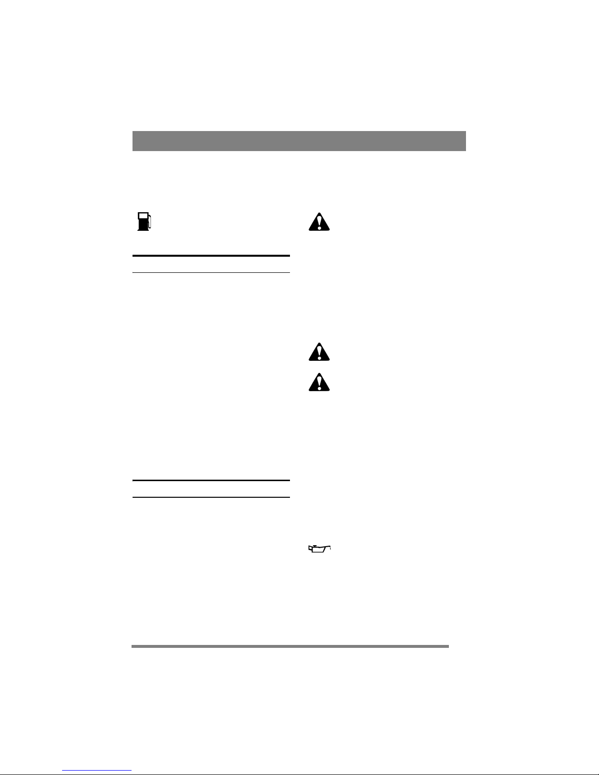
19. FUEL GAUGE/FUEL CAP
Fuel cap with built-in fuel gauge that indi-
cates how much fuel there is in the fuel
tank (applies to MF 880, MF 890 PRO).
The fuel tank holds approx. 11.5 litres.
AREAS OF USE
The machine may only be used for the following
tasks using the genuine accessories stated.
1. Mowing
Using cutting deck AMM 842, AME 842,
AMM 848, AME 848, AMM 842 HD,
AME 842 HD or flail mower ASM 836.
2. Snow clearance
Using snow blade ASS 847. Snow chains
ASK 416, ASK 817 and frame weights
AMG 175 are recommended.
The maximum vertical load on the towing hitch
must not exceed 100 N.
The maximum over-run load on the towing hitch
from towed accessories must not exceed 500 N.
NOTE! Before using a trailer – contact your insurance company.
NOTE! This machine is not intended to be driven
on public roads.
STARTING AND OPERATION
ENGINE CASING
To inspect and maintain the engine and battery, remove the engine casing. Dismantling:
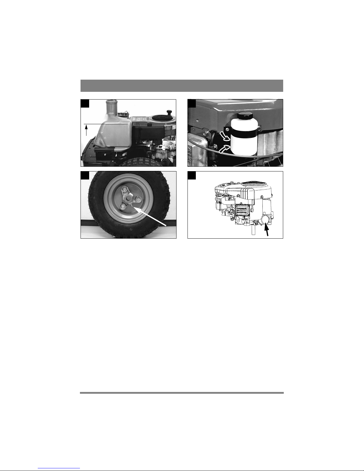
1. Unscrew the fuel cap/fuel gauge.
2. Pull up the rubber strap at the front edge of the
casing (fig. 7).
3. Carefully lift off the engine casing (fig. 8).
Assembly:
1. Place the casing over the lip on each side.
2. Make sure that the pins on the rear edge of the
casing go down into the respective holes (fig.
9).
3. Secure the front edge of the casing with the rubber strap (fig. 7).
4. Finally, screw in the fuel cap/fuel gauge.
The machine may not be operated unless the engine casing is mounted. Risk
of burns and crushing injuries.
FILLING THE FUEL TANK
Always use lead-free petrol. You must never use 2stroke petrol mixed with oil.
NOTE! Bear in mind that ordinary lead-free petrol
is a perishable; do not purchase more petrol than
can be used within thirty days.
Environmental petrol can be used, i.e. alkylate petrol. This type of petrol has a composition that is
less harmful for people and nature.
Petrol is highly inflammable. Always
store fuel in containers that are made
especially for this purpose.
Only fill or top up with petrol outdoors,
and never smoke when filling or topping up. Fill with fuel before starting
the engine. Never remove the filler cap
or fill with petrol while the engine is
running or still warm.
Never completely fill the petrol tank. Leave an
empty space (= at least the entire filler tube plus 1
- 2 cm at the top of the tank) to allow the petrol to
expand when it warms up without overflowing
(fig. 17).
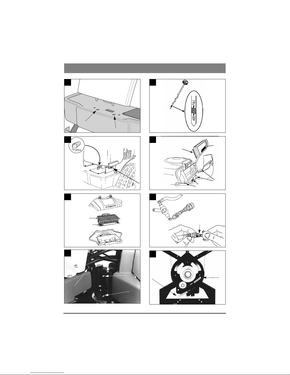
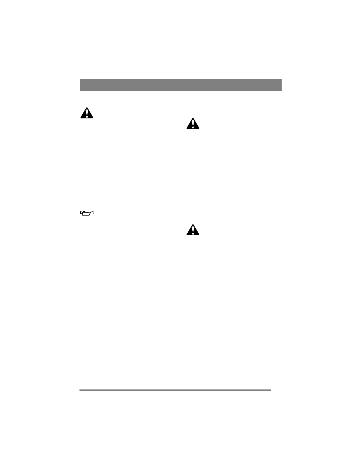
CHECKING THE ENGINE OIL LEVEL
On delivery, the crankcase is filled with SAE 30
oil.
Check the oil level every time before using to
ensure it is correct. The machine should be
standing on level ground.
Wipe clean around the oil dipstick. Unscrew and pull it up. Wipe off the dipstick.
Slide it down completely and tighten it.
Then unscrew it and pull it up again. Read off the
oil level. Top up with oil to the “FULL“ mark, if
the level comes below it (figs. 10).

20
ENGLISH
EN
CHECKING THE TRANSMISSION
OIL LEVEL
The transmission is filled with SAE 10W-40 oil
when the machine is delivered from the factory,
Check the oil level every time before using to
ensure it is correct. The machine should be
standing on level ground.
Read off the oil level in the reservoir (fig. 18). It
should be between the “MAX” and “MIN” marks.
If necessary, top up with more oil. Use oil SAE
10W-40 (20W-50).
SAFETY SYSTEM
This machine is equipped with a safety system that
consists of:
- a switch at the brake pedal.
- a switch in the seat (MF 860) or the seat bracket
(MF 880, MF 890 PRO).
- a switch at the power take-off engagement lever.
In order to start the machine, the following are necessary:
- brake pedal pressed down.
- driver sitting on seat.
- power take-off engagement lever in forward position (i.e. power take-off disengaged).
Always check the operation of the safety system before using the machine!
With the engine running and the driver sitting on
the seat, check as follows:
press the drive pedal so that the machine starts
to move, release the drive pedal – the machine
must stop.
- press the drive pedal so that the machine starts
to move, engage the cruise control, lift your
weight off the seat – the machine must stop (applies to MF 880, MF 890 PRO).
- press the drive pedal so that the machine starts
to move, engage the cruise control, press the
brake pedal – the machine must stop (applies to
MF 880, MF 890 PRO).
- engage the power take-off, lift your weight off
the seat – the engine must stop.
Do not use the machine if the safety system is not working! Take the machine
to a service workshop for inspection!
STARTING ENGINE
1. Open the fuel cock (fig. 11).
2. Make sure that the spark plug cable is properly
in place.
3. Check to make sure that the power take-off is
disengaged.
4. Do not keep your foot on the drive pedal.
5a. MF 860:
Starting cold engine – put the throttle control in the
choke position. Starting warm engine – put the
throttle control at full throttle (approx. 1 cm behind
the choke position).
5b. MF 880, MF 890 PRO:
Put the throttle control at full throttle. Starting cold
engine – pull the choke control out fully. Starting
warm engine – do not touch the choke control.
6. Depress the brake pedal fully.
7. Turn the ignition key and start the engine.
8a. MF 860:
Once the engine has started, move the throttle control gradually to full throttle if the choke has been
used.
8b. MF 880, MF 890 PRO:
Once the engine has started, push the choke control
in gradually if it has been used.
9. When starting from cold, do not make the machine work under load immediately, but let the engine run for a few minutes first. This will allow the
oil to warm up.
When in use, always operate the engine at full
throttle.
STOPPING
Disengage the power take-off. Apply the parking
brake.
Allow the engine to idle 1 - 2 mins. Stop the engine
by turning off the starter key.
Shut off the petrol cock. This is particularly important if the machine is to be transported on a trailer
for example.
If the machine is left unattended, remove the spark plug cable from the
spark plug. Also remove the starter key.
21
ENGLISH
EN
The engine may be very warm immediately after it is shut off. Do not touch the
silencer, cylinder or cooling fins. This
can cause burn injuries.
STEERING AID (MF 890 PRO)
Built-in function in order to facilitate steering. The
operator only has to turn the steering wheel gently.
A hydraulic torque amplifier creates the remaining
force.
As opposed to normal servo steering (e.g. in a car),
the steering aid has a limited capacity. This means
that it has some characteristics that might be considered negative:
- at a low engine rpm or in situations where extra
steering force is needed, steering can be considered to be “jumpy”.
- the machine should always be moving when the
steering is used. Avoid turning the steering
wheel when the machine is standing completely
still and the accessory is in the lowered working
position.
The steering is adapted in order to produce better
results at a normal working speed. This produces
major benefits.
Even when the engine is not running, the steering
works. However, it is harder to turn in this case, if
the machine is to be manoeuvred manually.
DRIVING TIPS
Make sure that there is the correct quantity of oil in
the engine when driving on slopes (oil level on
“FULL”).
Be careful when driving on slopes. No
sudden starting or stopping when moving up or down a slope. Never drive
across a slope. Move from the top down,
and from the bottom to the top.
The machine, equipped with original
accessories, may not be driven on slopes
greater than 10º in any direction.
Reduce the speed on slopes and when
making sharp turns to prevent the machine from tipping over or you losing
control of the machine.
Do not turn the steering wheel to full
lock when driving in top gear and at full
throttle. The machine can easily topple
over.
Keep hands and fingers well away from
articulated steering joint and seat
bracket. Risk of crushing injuries. Never operate the machine without the engine casing.
SERVICE AND MAINTENANCE
SERVICE PROGRAM
We recommend that an authorised workshop carries out every service. This guarantees that the
work is performed by trained personnel and with
genuine spare parts.
PREPARATIONS
Unless otherwise stated, all service and maintenance must be carried out on a stationary machine
when the engine is not running.
Prevent the machine from rolling by always applying the parking brake.
Prevent unintentional starting of the
engine by always stopping the engine,
disconnecting the spark plug cable
from the spark plug and earthing it.
Disconnect the negative cable from the
battery.
CLEANING
To reduce the risk of fire, keep the engine, silencer, battery and fuel tank free
from grass, leaves and oil.
To reduce the risk of fire, regularly
check the machine for oil and/or fuel
leakage.
When washing the machine with water under high
pressure, do not point the jet directly at the transmission.
Do not point jets of water directly at the engine.
Use a brush or compressed air in order to clean it.
ENGINE OIL
Change the oil for the first time after 5 hours running, and then after every 50 hours running or once
a season. Change oil when the engine is warm.
Always use a good grade of oil (service grade SF,
SG or SH).
Change the oil more often (after 25 hours of oper-

22
ENGLISH
EN
ation or at least once a season) if the engine has to
operate under demanding conditions or if the ambient temperature is high.
The engine oil may be very hot if it is
drained off directly after the engine is
shut off. So allow the engine to cool a
few minutes before draining the oil.
1. Oil drain pipe (metal):
Unscrew the oil drain plug at the end of the pipe.
Collect the oil in a collection vessel. Then take
the oil to a recycling station. Do not allow oil to
get on the V-belts.
2. Screw in the oil drain plug. Make sure that the
fibre gasket and the O-ring inside the plug are not
damaged and that they are in the correct place.
3. Remove the dipstick and fill up with new oil.
Oil capacity: 1.4 l
Oil type, summer (> 4ºC): SAE-30
(SAE 10W-30 can also be used. However, oil consumption may increase somewhat if 10W-30 is
used. Therefore, check the oil level more regularly
if you use this type of oil).
Oil type, winter (< 4ºC): SAE 5W-30
(if this oil is not available, use SAE 10W-30).
Use oil without any additives.
Do not fill with too much oil. This can cause the
engine to overheat.
After filling up the oil, start the engine and idle for
30 seconds. Stop the engine. Wait for 30 seconds
and then check the oil level.
Check to see if there is any oil leakage. If necessary, fill up the oil up to the “FULL“ mark.
OIL FILTER – ENGINE
(MF 880, MF 890 PRO)
Replace the oil filter after every 100 hours of operation or once a season.
Before screwing the new filter, oil the filter gasket
with engine oil.
Screw the filter by hand, until the filter gasket
touches the filter attachment. Then tighten ½ to ¾
of a full turn (fig. 20).
Start the engine and idle to see if any leakage occurs. Stop the engine. Check the oil level. If necessary, fill up the oil up to the “FULL” mark.
AIR FILTER - ENGINE
Clean the foam pre-filter every 3 months or after
every 25 hours of operation, whichever comes
first.
Clean the paper filter insert once a year or after
every 100 hours of operation, whichever comes
first.
Note! Both filters should be cleaned more often if
the machine operates on dusty ground.
1. Remove the protective cover of the air filter (fig.
12-13).
2. Dismantle the paper filter insert and the foam
pre-filter. Make sure that no dirt gets into the carburettor. Clean the air filter housing.
3a. MF 880, MF 890 PRO
Wash the pre-filter in liquid detergent and water.
Squeeze dry. Pour a little oil on the filter and
squeeze in the oil.
3b. MF 860
Replace the pre-filter once a year or after every 25
hours of operation, whichever comes first.
4. Clean the paper filter insert as follows: Knock it
lightly against a flat surface. If the filter is very
dirty, change it.
5. Assemble in the reverse order.
Petroleum-based solvents such as kerosene may
not be used for cleaning the paper filter insert.
These solvents can destroy the filter.
Do not use compressed air for cleaning the paper
filter insert. The paper filter insert must not be
oiled.
SPARK PLUG
Only use a Briggs & Stratton sparking tester to
check the spark in the sparking plug (fig. 14).
Clean the spark plug after every 100 hours of operation or once a season. For replacing a spark plug,
a spark plug sleeve A and a torsion pin B are provided in the accessories bag.
The engine manufacturer recommends:
Champion RC12YC
Correct spark gap: 0.75 mm.
COOLING AIR INTAKE - ENGINE
The engine is air-cooled. A blocked cooling system can damage the engine. The engine should be

23
ENGLISH
EN
cleaned at least once a year or every 100 hours of
operation.
Remove the fan casing. Clean the cooling fins on
the cylinder, the fan and the rotating protective
grille. Clean more frequently if mowing dry grass.
BATTERY
The battery is a valve-regulated battery with 12 V
nominal voltage. The battery is completely maintenance free. You don’t have to check or top up the
electrolyte level.
On delivery, the battery is in the accessories box.
The battery must be fully charged before being used for the first time. The
battery should always be stored fully
charged. If the battery is stored while
totally flat it could sustain permanent
damage.
If the machine is not going to be used for an extended period (more than 1 month), the battery
should be charged, disconnected and then stored in
a cool, safe place. Charge the battery completely
before reinstalling.
The battery can be charged in two ways:
1. You can allow the engine to charge the battery.
In this case it is very important, above all when
starting the machine for the first time and when
it has not been used for a long time, to allow the
engine to run continuously for at least 45 minutes.
2. Via a battery charger. This must be a charger
with constant voltage. The battery can be damaged if a standard type battery charger (for acid
batteries) is used.
Do not short circuit the battery’s terminals. Sparks occur which can result in
fire. Do not wear metal jewellery which
can come into contact with the battery
terminals.
In the event of damage to the battery
casing, cover, terminals or interference
to the strip covering the valves, the battery should be replaced.
If the battery terminals are coated with oxide, they
should be cleaned. Clean the battery terminals with
a wire brush and grease them.
LUBRICATION
The machine’s articulated steering joint has four
grease nipples that should be lubricated with universal grease after every 25 hours of operation (fig.
15).
Note: The fourth grease nipple is not shown on the
picture. It is located on the underside, on the flexible axle’s front bearing.
Lubricate the steering chain with chain spray a
couple of times per season.
The front wheel hub has grease nipples that should
be lubricated after every 50 hours of operation (fig.
19).
Apply universal grease to all the plastic bearings a
couple of times per season.
Apply a coating of engine oil to the tension arm
joints a couple of times each season.
Apply a few drops of engine oil to both ends of the
throttle control cables a couple of times a season.
The hydrostatic transmission is filled with oil
(10W-40) on delivery from the factory. Unless it is
opened (only to be performed by a specialist), and
provided no leakage occurs, no topping up with oil
should normally be carried out. Transmission oil
does not normally need to be changed.
STEERING CABLES
(MF 860, MF 880)
The steering cables should be adjusted for the first
time after the machine has been in operation for 2
- 3 hours, and then after every 25 hours of operation.
Put the machine in the straight-ahead position.
Tension the steering cables by tightening the nuts
that are located on the underside of the articulated
steering joint (fig. 16). The screws in the ends of
the cables should be held firmly during adjustment
so that the cables are not twisted. Use an adjustable
wrench or similar for this purpose, inserting it in
the key handles in the ends of the screws. Tension
until all play is removed.
Adjust both the nuts the same amount to ensure
that the alignment of the steering wheel is not
changed.
Once the adjustment is complete, turn the steering
wheel as far as it will go in either direction. Check
that the chain does not come into contact with the

24
ENGLISH
EN
pulley, and that the cables do not become entangled with the steering pinions.
Do not tension the steering cables too hard. Otherwise the steering will be heavy and wear and tear
on the cables will increase.
STEERING CHAINS (MF 890 PRO)
The steering chains should be adjusted for the first
time after the machine has been in operation for 2
- 3 hours, and then after every 50 hours of opera-
tion.
Put the machine in the straight-ahead position.
Tension the steering chains by tightening up the
nuts that are located on the underside of the articulated steering joint (fig. 16). Tension until all play
is removed.
Adjust both the nuts the same amount to ensure
that the alignment of the steering wheel is not
changed.
Do not over-tighten the steering chains. This will
cause the steering to become heavy and will increase wear on the steering chains.
25
FRANÇAIS
FR
GÉNÉRALITÉS
Ce symbole signifie ATTENTION : risque de blessure ou de dégât matériel en
cas de non-respect des instructions.
Avant de démarrer la machine, lire attentivement les instructions ainsi que
les consignes contenues dans le fascicule
« RÈGLES DE SÉCURITÉ » ci-joint.
SYMBOLES
Les symboles suivants figurent sur la machine. Ils
attirent votre attention sur les dangers d’utilisation
et les mesures à respecter.
Explication des symboles :
Attention !
Lire le mode d’emploi et le manuel de sécurité avant d’utiliser la machine.
Attention !
Attention aux projections. Travailler à une
distance suffisante de toute présence.
Attention !
Porter des protections auditives.
Attention !
Cet engin n’est pas conçu pour circuler sur
la voie publique.
Attention !
La machine, équipée d’accessoires d’origine, ne peut en aucun cas être utilisée sur
des pentes dont l’inclinaison est supérieure à 10°.
Attention !
Risque de blessure par écrasement. Garder
les mains et les pieds à distance du joint de
direction articulé.
Attention !
Risque de brûlure. Ne pas toucher le silencieux ou le convertisseur catalytique.
RÉGLAGES ET INSTRUMENTS
Articles 1 - 19, voir figures 1 - 6.
1. DISPOSITIF DE LEVAGE
(MF 860, MF 880)
Pédale destinée à soulever en position de transport
les accessoires montés à l’avant.
Pour lever l’accessoire, enfoncer la pédale jusqu’en bout de course. Relâcher ensuite la pédale
pour bloquer le dispositif en position levée.
Pour abaisser l’accessoire, appuyer sur la pédale
pour la débloquer. Lever ensuite progressivement
le pied pour amener doucement l’accessoire en position de travail.
2. DISPOSITIF DE LEVAGE
HYDRAULIQUE (MF 890 PRO)
Dispositif de levage hydraulique permettant de
soulever en position de transport les éléments
montés à l’avant.
Pour soulever l’accessoire, appuyer
sur la partie arrière de l’interrupteur,
puis le relâcher dans la position souhaitée.
Pour abaisser l’accessoire, appuyer
sur la partie avant de l’interrupteur.
L’interrupteur reste en position enfoncée et le dispositif de levage
s’abaisse jusqu’à ce qu’il atteigne
une position de flottement, ce qui signifie que l’accessoire peut suivre le
relief du terrain.
La position de flottement, avec l’interrupteur basculé vers l’avant, est recommandée pour l’utilisation normale. Pour bloquer le dispositif de levage,
positionner l’interrupteur sur neutre.
REMARQUE ! Le dispositif de levage hydraulique doit être en position de flottement pour
que la prise de force soit connectée.
3. FREIN DE SERVICE
Pédale activant le système de freinage. Trois positions sont possibles :
1. Pédale relâchée – le frein de
service n’est pas activé.
2. Pédale enfoncée jusqu’à micourse – marche avant désenclenchée. Le frein de service
n’est pas activé.
26
FRANÇAIS
FR
3. Pédale enfoncée à fond – marche avant désenclenchée. Le
frein de service est totalement
activé.
4. FREIN DE STATIONNEMENT
Inhibiteur permettant de bloquer la pédale de frein
dans la position enfoncée.
Enfoncer à fond la pédale de frein. Déplacer l’inhibiteur vers la droite et relâcher la
pédale de frein.
Pour débloquer le frein de stationnement, appuyer
sur la pédale de frein. L’inhibiteur à ressort glisse
sur le côté.
Avant d’utiliser la machine, vérifier que le frein de
stationnement est relâché.
5. ACCÉLÉRATEUR
Pédale activant la transmission variable.
1. Enfoncer la pédale avec
l’avant du pied - la machine
avance.
2. Pas de pression sur la pédale –
la machine reste immobile.
3. Pression du talon sur la pédale
– la machine recule.
L’accélérateur règle la vitesse. Plus la pression sur
la pédale est importante, plus la vitesse de la machine augmente.
6. VOLANT RÉGLABLE
La hauteur du volant est réglagle en continu. Desserrer le bouton de réglage situé sur la colonne de
direction et mettre le volant à la hauteur adéquate.
Resserrer.
Ne pas modifier la hauteur du volant pendant le
fonctionnement de la machine.
7. PLEIN RÉGIME/CHOKE
Réglage du régime moteur, permettant d’enrichir
le mélange pour le démarrage à froid (pas pour les
modèles MF 880, MF 890 PRO dont le choke est
séparé – voir point 8).
1. MF 860: Starter - pour le démarrage du
moteur à froid. Le choke se situe dans la
partie supérieure de la rainure. Éviter
d’utiliser la machine dans cette position.
Veiller à passer en mode plein régime
(voir ci-dessous) lorsque le moteur est
chaud.
2. Plein régime – le mode plein régime
doit toujours être enclenché lorsque la machine fonctionne.
3. Ralenti.
8. RÉGLAGE DU CHOKE
(MF 880, MF 890 PRO)
Commande servant au démarrage du moteur à
froid.
1. Commande entièrement sortie - volet de
starter fermé dans le carburateur. Pour le
démarrage à froid.
2. Commande enfoncée – volet de starter
ouvert. Pour le démarrage à chaud et lors
de la conduite.
Ne jamais conduire la machine avec le starter
tiré lorsque le moteur est chaud.
9. DÉMARREUR/PROJECTEUR
Le démarreur permet de démarrer et d’arrêter le
moteur. Il intègre également un interrupteur pour
le phare. Quatre positions :
1. Position d’arrêt - le moteur est courtcircuité. La clé peut être retirée.
2. Position de conduite - phare allumé.
3. Position de conduite - phare éteint.
4. Position de démarrage - le démarreur
électrique est activé lorsque la clé est amenée sur la position de démarrage à ressort.
Lorsque le moteur tourne, la clé revient en
position de marche 3 grâce à un dispositif
à ressort.
Pour allumer le projecteur, tourner la clé en position 2.

27
FRANÇAIS
FR
10. PRISE DE FORCE
(MF 860, MF 880)
Levier permettant d’enclencher et de débloquer la
prise de force actionnant les accessoires montés à
l’avant. Deux positions sont possibles :
1. Levier vers l’avant – prise de force désengagée.
2. Position arrière – prise de force branchée.
11. PRISE DE FORCE (MF 890 PRO)
Levier permettant d’enclencher et de débloquer la
prise de force électromagnétique actionnant les accessoires montés à l’avant. Deux positions sont
possibles :
1. Appuyer sur la partie avant de l’interrupteur - la prise de force se branche. Le
symbole s’allume.
2. Pression sur la partie arrière de l’interrupteur – la prise de force est désengagée.
12. BLOCAGE DU DIFFÉRENTIEL
(MF 890 PRO)
Levier permettant de bloquer le différentiel. Les
deux roues arrière tournent alors simultanément,
ce qui augmente la capacité de remorquage. Deux
positions sont possibles :
1. Position avant - le blocage du différentiel n’est pas connecté. Pour le fonctionnement normal.
2. Levier vers l’arrière – blocage du différentiel enclenché. Fonctionne en marches
avant et arrière.
Le blocage du différentiel est très utile lorsque la
charge reposant sur les roues arrière est répartie de
manière inégale, par exemple dans les virages serrés, où la roue arrière située côté centre subit une
charge inférieure.
Grâce à ce dispositif, le véhicule non équipé de
chaînes possède une meilleure tenue de route sur
les surface glissantes en hiver.
La direction se durcit lorsque le blocage du différentiel est enclenché. Éviter de tourner le volant !
13. COMPTEUR D’HEURES
Indique le nombre d’heures de travail. Le compteur ne fonctionne que lorsque le moteur tourne.
14. RÉGULATEUR DE VITESSE
(MF 880, MF 890 PRO)
Un interrupteur permet d’activer le régulateur de
vitesse. Le régulateur de vitesse permet de bloquer
l’accélérateur dans la position souhaitée.
1. Enfoncer la pédale de commande pour
atteindre la vitesse souhaitée. Appuyer ensuite sur l’avant de l’interrupteur pour activer le régulateur de vitesse. Le symbole
s’allume.
2. Pour débloquer le régulateur, appuyer
sur l’arrière de l’interrupteur.
15. RÉGLAGE DE LA HAUTEUR DE
COUPE
La machine est équipée d’un dispositif permettant
d’utiliser un plateau à réglage électrique de la hauteur de coupe (disponible comme accessoire).
Le variateur permet d’adapter en continu
la hauteur de coupe.
La prise de raccordement du plateau de coupe est
située sur le côté droit, devant la roue avant (fig. 3).
16. RÂTEAU ARRIÈRE (MF 890 PRO)
La machine permet le réglage électrique du râteau
arrière (disponible comme accessoire).
L’interrupteur permet de soulever et
d’abaisser le râteau.
Les câbles de branchement du râteau se situent à
l’arrière de la machine, sur la gauche de la partie
supérieure du pare-chocs.
17. ÉPANDEUR DE SABLE
(MF 890 PRO)
La machine permet le réglage électrique d’un
épandeur de sable (disponible comme accessoire).
L’interrupteur permet de démarrer et d’arrêter l’épandeur.
La prise de connexion de l’épandeur est située à
l’arrière de la machine, à gauche de la partie supérieure du pare-chocs.
12V
28
FRANÇAIS
FR
18. LEVIER DE DÉBRAYAGE
Levier permettant de débrayer la transmission variable, ce qui permet de bouger la machine à la
main, moteur éteint. Deux positions sont possibles:
1. Levier vers l’arrière - la transmission est activée pour une utilisation normale.
2. Levier vers l’avant – débrayage de la transmission. La machine peut être déplacée
manuellement.
Ne pas remorquer la machine sur de longues distances ou à des vitesses élevées pour éviter d’endommager la transmission.
19. JAUGE DE CARBURANT/
BOUCHON DE RÉSERVOIR
Le bouchon de réservoir avec jauge incorporée indique la quantité de carburant présente dans le réservoir (MF 880,
MF 890 PRO).
Le réservoir de carburant a une contenance d’environ 11,5 litres.
UTILISATION
L’usage de la machine est réservé aux travaux suivants, avec les accessoires d’origine renseignés.
1. Tonte
Utiliser les plateaux de coupe AMM 842,
AME 842, AMM 848, AME 848,
AMM 842 HD, AME 842 HD ou le scarificateur ASM 836.
2. Déneigement
Avec la pelle à neige ASS 847. Chaînes à neige
ASK 416, ASK 817 et poids de lestage
AMG 175 recommandées.
La charge verticale maximum exercée sur la boule
de remorquage doit être inférieure à 100 N.
La charge d’inertie maximum exercée sur la boule
de remorquage par les accessoires tractés doit être
inférieure à 500 N.
REMARQUE ! Avant d’utiliser un tracteur, contactez votre compagnie d’assurance.
REMARQUE ! Cette machine n’est pas conçue
pour circuler sur la voie publique.
DÉMARRAGE ET
FONCTIONNEMENT
CARTER DE MOTEUR
Pour procéder à l’inspection et à l’entretien du moteur et de la batterie, retirer le carter de moteur. Démontage :
1. Dévisser le bouchon et la jauge de carburant.
2. Tirer vers le haut la sangle en caoutchouc située
à l’avant du carter (fig. 7).
3. Soulever prudemment le carter (fig. 8).
Assemblage:
1. Placer le carter sur la lèvre située de chaque côté.
2. Veiller à ce que l’arrière du carter s’emboîte correctement dans les trous prévus (fig. 9).
3. Attacher l’avant du carter au moyen de la sangle
(fig. 7).
4. Enfin, remettre en place le bouchon et la jauge
de carburant.
Ne pas utiliser la machine si le carter de
moteur n’est pas monté. Risque de brûlure et de blessure par écrasement.
REMPLISSAGE DU RÉSERVOIR DE
CARBURANT
Utiliser uniquement du carburant sans plomb. Ne
jamais utiliser de mélange carburant-huile 2
temps.
REMARQUE ! L’essence sans plomb ne se conserve pas indéfiniment. Ne pas l’utiliser au-delà de
trente jours après l’achat.
Des carburants respectueux de l’environnement,
par ex. l’essence alkylate, peuvent également être
utilisés. Par leur composition, ils ont un impact réduit sur la nature et la santé.
L’essence est très inflammable et doit
être conservée dans des récipients spécialement conçus à cet effet.
29
FRANÇAIS
FR
Faire le plein d’essence uniquement à
l’extérieur, et ne pas fumer pendant
l’opération. Faire le plein de carburant
avant de démarrer le moteur. Ne jamais
enlever le bouchon du réservoir ou procéder au remplissage quand le moteur
tourne ou est encore chaud.
Ne pas remplir le réservoir à ras bord. Laisser un
espace vide (= au moins tout l’embout du pistolet
de remplissage plus 1 - 2 cm de la partie supérieure
du réservoir) afin que l'essence, une fois chaude,
puisse se dilater sans risquer de déborder (fig. 17).
CONTRÔLE DU NIVEAU D'HUILE DE
LA TRANSMISSION
À la livraison, le carter est rempli d’huile SAE 30.
Vérifier le niveau d’huile avant chaque utilisation. Placer la machine sur un sol plat.
Nettoyer la zone autour de la jauge d’huile. La dévisser et la sortir du carter. Essuyer la jauge au moyen d’un chiffon,
Réintroduire la jauge dans le carter et la
visser à fond.
Dévisser la jauge et la ressortir. Lire le niveau
d’huile sur la jauge. Si le niveau d’huile descend
en dessous du repère « FULL », faire l’appoint
(fig. 10).
NIVEAU D’HUILE DE
TRANSMISSION
À la sortie d’usine, la transmission de la machine
est remplie d’huile SAE 10W-40.
Vérifier le niveau d’huile avant chaque utilisation. Placer la machine sur un sol plat.
Vérifier le niveau d’huile dans le réservoir (fig.
18). Il doit se situer entre les repères « MAX » et «
MIN ». Si nécessaire, faire l’appoint. Utiliser de
l’huile SAE 10W-40 (20W-50).
DISPOSITIFS DE SÉCURITÉ
La machine est équipée des dispositifs de sécurité
suivants :
- un disjoncteur au niveau de la pédale de frein.
- un interrupteur dans le siège (MF 860) ou dans
son support (MF 880, MF 890 PRO).
- un disjoncteur sur le levier d’enclenchement de
la prise de force.
Pour démarrer la machine, vérifier que les points
suivants sont respectés :
- enfoncer la pédale de frein.
- le conducteur doit être assis sur le siège.
- le levier de la prise de force doit être vers
l’avant (c.-à-d. prise de force désactivée).
Vérifier le bon fonctionnement des dispositifs de sécurité avant toute utilisation de la machine!
Lorsque le moteur tourne et que le conducteur est
assis sur le siège, procéder aux vérifications suivantes :
- enfoncer l’accélérateur pour mettre la machine
en mouvement, puis la relâcher – la machine
doit s’arrêter.
- enfoncer l’accélérateur pour mettre la machine
en mouvement, actionner le régulateur de vitesse et se lever du siège – la machine doit s’arrêter
(modèles MF 880, MF 890 PRO).
- enfoncer l’accélérateur pour mettre la machine
en mouvement, actionner le régulateur de vitesse et enfoncer la pédale de frein – la machine
doit s’arrêter (modèles MF 880, MF 890 PRO).
- enclencher la prise de force et se lever du siège
– le moteur doit s’arrêter.
Ne pas utiliser une machine dont les dispositifs de sécurité sont déficients ! Faire contrôler la machine dans un atelier
agréé !
DÉMARRAGE DU MOTEUR
1. Ouvrir le robinet de carburant (fig. 11).
2. Vérifier que le câble de la bougie d’allumage est
bien branché.
3. Vérifier que la prise de force n’est pas activée.
4. Ne pas laisser le pied sur l’accélérateur.
5a. MF 860:
Démarrage à froid du moteur – mettre la manette
en position choke. Démarrage à chaud – mettre la
manette sur plein régime (environ 1 cm plus loin
que la position choke).
5b. MF 880, MF 890 PRO:
ramener la commande d’accélérateur sur la position pleins gaz. Démarrage à froid – tirer le choke
à fond. Démarrage à chaud – ne pas toucher au
choke.
6. Enfoncer à fond la pédale de frein.
7. Démarrer le moteur en tournant la clé de contact.
8a. MF 860:
30
FRANÇAIS
FR
après le démarrage du moteur, amener progressivement la pédale de commande à la position pleins
gaz si le starter a servi au démarrage.
8b. MF 880, MF 890 PRO:
après le démarrage du moteur, enfoncer progressivement la commande du starter si celui-ci a été utilisé.
9. Ne pas utiliser la machine pour des travaux sous
charge immédiatement après un démarrage à froid.
Laisser d'abord tourner le moteur pendant quelques minutes pour permettre à l’huile de chauffer.
Le moteur doit toujours être utilisé à plein rendement.
ARRÊT
Désactiver la prise de force. Serrer le frein de stationnement.
Laisser tourner le moteur au ralenti pendant 1 à 2
minutes. Arrêter le moteur en tournant la clé.
Fermer le robinet de carburant. Ce point est particulièrement important si la machine doit être transportée par camion, par exemple.
Si la machine est abandonnée sans surveillance, retirer le câble de la bougie
d'allumage. Ôter également la clé du
démarreur.
Le moteur peut être très chaud immédiatement après l’arrêt. Ne pas toucher
le pot d’échappement, le cylindre ni les
ailettes de refroidissement. Risque de
brûlure.
DIRECTION ASSISTÉE
(MF 890 PRO)
Fonction intégrée qui facilite la conduite. La machine se conduit du bout des doigts. Un convertisseur de couple hydraulique fournit la force
nécessaire.
Contrairement à la direction assistée courante (par
ex. celle des voitures), l’aide au pilotage a une capacité restreinte. Cela signifie que certaines de ses
caractéristiques peuvent être considérées comme
négatives :
- à faible régime ou dans des situations exigeant
une puissance supplémentaire, la direction peut
sembler fonctionner « par à-coups ».
- la machine doit toujours être en mouvement
quand la direction assistée est utilisée. Éviter de
tourner le volant lorsque la machine est à l’arrêt
complet et que l’accessoire est abaissé en position de travail.
La direction est adaptée de manière à fournir les
meilleurs résultats à des vitesses de travail normales, avec pour résultat des avantages significatifs.
La direction fonctionne même lorsque le moteur
est à l’arrêt. Toutefois, elle est dans ce cas plus
dure si la machine doit être manœuvrée à la main.
CONSEILS DE CONDUITE
Pour la tonte sur terrains en pente, s’assurer que le
moteur contient suffisamment d’huile (niveau
d’huile sur « FULL »).
Redoubler de vigilance sur les terrains
en pente. Ne pas démarrer ou s’arrêter
brutalement sur un terrain en pente. Ne
jamais circuler perpendiculairement à
une pente. Se déplacer de haut en bas, et
de bas en haut.
La machine, équipée d’accessoires
d’origine, ne peut en aucun cas être utilisée sur des pentes dont l’inclinaison
est supérieure à 10°.
Ralentir dans les pentes et dans les virages pour éviter de basculer ou de perdre
le contrôle de la machine.
Ne pas braquer à fond lorsque la machine est en vitesse supérieure et à plein
régime. Dans cette situation, elle pourrait facilement basculer.
Garder les mains et les doigts à distance
des éléments articulés et du support du
siège. Risque de blessure par écrasement. Ne pas utiliser la machine sans le
carter de moteur.
ENTRETIEN
PROGRAMME D’ENTRETIEN
Il est recommandé de confier les entretiens à des
ateliers agréés. Les travaux y seront effectués par
du personnel expérimenté n’utilisant que des pièces d’origine.
PRÉCAUTIONS
Sauf indication contraire, les interventions et entretiens doivent s’effectuer sur des machines immobilisées dont le moteur est à l’arrêt.
 Loading...