

Page 1
Operating Instruction Manual
TOA POWERED MIXER
Model MCX-106
TOA ELECTRIC CO., LTD.
KOBE, JAPAN
Page 2
Contents
General Description
Features
Front Panel [Input Section]
Front Panel [Output Section]
Front Panel [Stereo Cassette Recorder Section]
Front Panel [Patch Bay & Bus Link]
Rear Panel
Connection Examples
Input Connections
How to get a good mix.
Recording Level Setting
Type of Cassette Tape
Maintenance of Stereo Cassette Deck
Block and Level Diagrams
Specifications
Characteristic Diagrams
Appearance
Precautions
1. XLR Type Audio Connector
The connectors are wired as follows.
The pin 1 is ground (shield), the pin 2 cold (low,
minus), the pin 3 hot (high, plus).
MCX-106™ Operating Guide
A Few Words about design:
The MCX™ is quite an unusual product, but the
reasoning behind its design was quite simple .... we
wanted to intergrate all the basic components of a
sound reinforcement system and a recording studio
into a single, transportable package.
The basic components of the MCX™ are as follows:
1. Six-channel main mixer.
2. Six-channel on-stage monitor mixer.
3. Six-channel special effects mixer.
4. Six-channel recording mixer.
5. Stereo tape deck.
2. Description of components and functions on the
MCX-106.
Descriptions may vary, depending on each manufacturer. In our Operating and Instruction Manual
explanation of components and functions is made
according to our usage for them.
6. One-octave equalizer.
7. Patch bay.
8. Headphone cue/monitor system.
9. Three-hundred watt power amplifier.
10. Road case.
Each of these "components" functions independently
of the others, although some do share common signal
processing and control circuitry. For example, the
main mixer, effects mixer, and recording mixer all
make use of the same input equalization on each of the
six channels. And the input trim control performs the
same function for all four mixing sections.
— 1 —
Page 3

General Description
The MCX-106 is a compact self-powered mixer with a Microprocessor controlled stereo
cassette deck, designed to allow recording a live demo tape, performing to pre-recorded
program material, recording sound on sound with an external tape source, and
simultaneously performing as a six-channel "powered" main sound system and a six-
channel independent monitor mixer.
The MCX-106 fea ture s: six i nput channels, a 300 watt power amplifier, 9-band graphic
equalizer, automatic compressor, reverb effect, fluorescent bargraph meter, power
amplifier protection circuitry, and a complete patch bay.
Each input channel features: input trim control with LED peak indicator, pre-EQ foldback
send, 3-band EQ, post-EQ recording level and pan controls, post-reverb/effects send, Lo-
Z balanced XLR input and Hi-Z unbalanced 1/4" input.
The built-in cassette deck features: full logic cassette mechanism control, dbx noise
reduction system, zero return and cue functions, automatic tape selector.
All these unique functions are integrated into a ruggedly construct and portable package,
offering unlimited applications for school, church, band, performing group, etc.
The MCX-106 is a "first of its kind" product, providing such a wide variety of versatility.
Features
1. Built-in Stereo Cassette Recorder with micro-
processor control
2. Six Input Channels
3. 300 watt Power Amplifier
4. 9-band Graphic Equalizer with Bypass Switch
5. Auto-Comp™ Compression Circuitry with LED
indicator
6. Reverberation Effect with 2-band dedicated EQ
7. Fluorescent Bargraph Metering— assignable
8. Power Amp Protection Circuitry with indicator
9. Complete patch Bay with Buss-Link™
10. Aux. Input with Stereo Balance and Level
Controls — assignable to PGM, FB, and Rec L & R
Busses
11. Headphone Monitoring/Cueing System
12. Independent Stage Monitor (FB) Mix
Each Channel
1. Input Trim Control with LED peak indicator
2. Pre-EQ foldback send
3. 3-Band EQ
4. Post-EQ recording level and pan controls
5. Post reverb/effects send
6. Lo-Z Balanced XLR Input
7. Hi-Z Unbalanced 1/4" Input
Stereo Cassette Recorder
1. Full Logic Cassette Mechanism Control
2. dbx® Noise Reduction System
3. Automatic Tape Selector with Indicator (normal,
CrO2 Metal)
4. Headphone Output with Level Control
5. Tape Transport Remote Control (start/stop)
6. Tape Pitch Control (±10%)
7. Zero Return with Automatic Cue
8. 3-Digit Tape Counter
— 2 —
Page 4
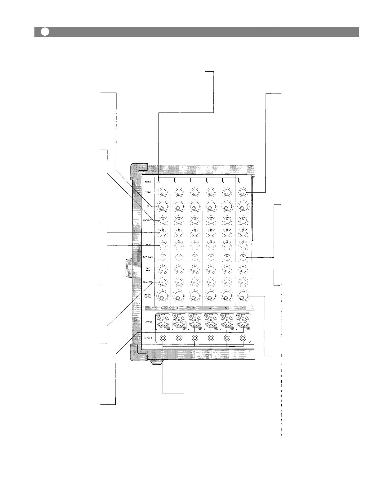
Front Panel, Input Section
Foldback Control (FB)
The Foldback control determines the level of signal assigned to the foldback mixing buss,
thus setting the level of t h at
channel in the on-stage monitor
mix.
High Equalizer Control
The high EQ control alters the
high frequency response of t he
input channel, providing ±13dB
at 10kHz, and ±15dBat 20kHz of
continuously variable active
shelving equalization. The "0"
detented position provides fla t
audio response.
Middle Equalizer Control
The mid EQ control provides
±15dB of continuously variable
active peaking equalization at
2kHz. and has a flat audio response when set to the "0"
detented position.
(HIGH EQ)
(MID
EQ)
Peak Indicator (PEAK)
The peak indicator lights when
the pre or post EQ signal level
reaches 3dB below cli ppi ng,
giving a visual reference for
optimum setting of the trim control.
Input Trim Control (TRIM)
The input trim adjusts the gain
of the head-amp stage of the as-
sociated channel, providing 39
dB of gain control. When the
trim control is set to the "10"
position, the nominal input
levels of t he low-Z and high-Z
inputs are — 55dB and —35dB re-
spectively. At the "0" position
the levels are -16dB and +4dB.
The trim of each channel should
be adjusted so that the peak LED
j u s t be gin s to l ig ht , or o nly
flashes occasionally. This will
ensure lowest distortion levels
and optimum signal to noise
ratio.
Recording pan Pot
(REC
PAN)
This control assigns the recording signal from each channel to
the recording L and R mixing
busses. At the center position,
the pan pot routes the signal
equally to the L and R mixing
busses. Panning from one side to
the other gradually assigns the
input signal to either the record-
ing L or R mixing bus exclusive-
ly!
Low Equalizer Control
The low EQ control provides
±13dB at l00Hz and ±15dB at
50Hz (of continuously variable
active shelving equalization.
The "0" detented position provides flat audio response.
Reverb/Effects Control
This
control
level of signal assigned to th e reverb effects buss. Rotating the
control clockwise increases t he
amount of reverb effect in that
channel.
(LOW
(REV/EFF)
determines
EQ)
the?
Low Impedance Connectors
(LOW
The XLR connectors are low im-
pedance, electronically balanced
inputs with an input impedance
of 1k ohms.
Z)
High Impedance Connectors
(HIGH Z)
These connectors are unbalanced, standard 1/4" phone jacks
with an input impedance? of 50k
ohms, and an input level of
—35dB when t he tri m control is
set to "10". When a plug is inserted into the high —Z input, the cor-
responding XLR connector is
automatically switched out of
the input circuitry.
Recording Level J Control
(REC LEVEL)
This control adjusts the level of
signal assigned to th e tape deck
via the recording pan pot and
stereo L and R recording busses.
Rota ting the control clockwise
increases the amount of signal
assigned to the recording L and R
busses and t hu s the level of t ha t
input in the "recording mix."
Input Level Control
(INPUT LEVEL)
The level control provides continuously variable adjustment
of the channel output to the
program mixing buss, t hu s determining the level of that
channel in the main sound
system mix. Since t he reverb/
effects
signal
is
"post"
this
trol, an increase in the level of the
channel's output will also result
in a corresponding increase in
he reverb effect of that channel.
The nominal level of the input
level control is at the "10" posi-
tion.
con-
— 3 —
Page 5
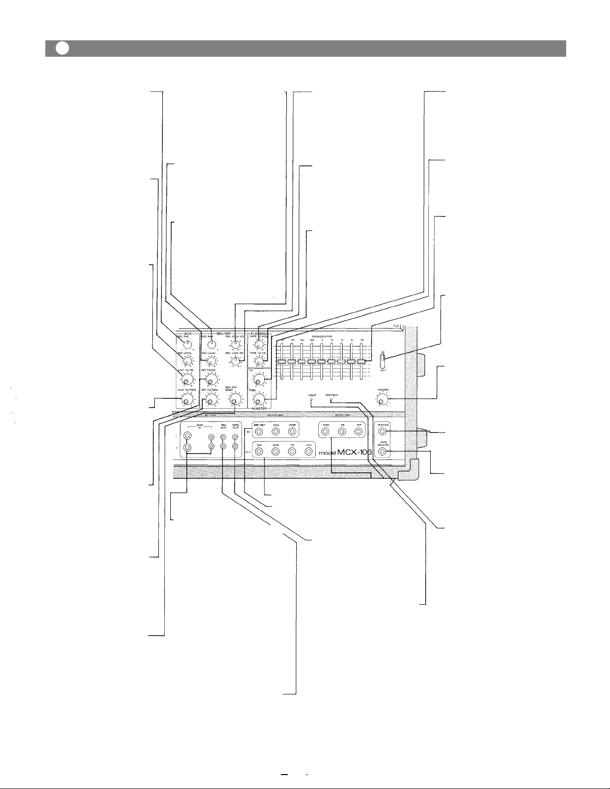
Front Panel, Output Section
Aux Recording Balance
(AUX
REC
Th is c on tr ol ad j u st s t h e l ev el
balance of the aux in, L and R
signals routed to the L and R
mixing busses.
At the center position, the balance control routes the signal
equally to the L and R mixing
busses.
BAL)
Auxiliary Input Recording
Level Control
This control sets the level of
stereo L and R signal (from an
external source connected to the
AUX INPUT) assigned t o the recording busses, via the AUX
REC BAL control.
(AUX REC LEVEL)
Auxiliary Input to
Foldback Control
((AUX
(AUX
TO FB)
TO
Control
PGM)
This control sets the level of aux
input signal assigned to t he foldback mixing bus, and thus the
level of the exter nal aux source
in the on-stage monitor mix.
NOTE: If t he au x source is a
stereo L and R signal (for
example, a stereo cassette player) the L and R
will be combined i nt o
one mono signal before
assignment to either the
FB or PGM mixing busses.
Auxiliary Input to Program
This control sets the level of aux
input signal assigned to the
program mixing bus, and thus
the level of the external aux
source in the main mi x.
Effect to Foldback Control
(EFF
This control determines the
level of reverb/effects return
signal assigned to the foldback
mixing buss, and th us t he
amount of effects in the on-stage
TO FB)
monitor mix.
Reverb/Effects to Program-
Control
(EFF
TO
This control adjusts the amount
of reverb/effects signal that is
returned to the program buss
and thus th e level of reverb/
effects contained in the main
PGM)
sound system.
Reverb/Effects Send Control
This control ad jus ts the overall
signal level of the effects mix
th a t is delivered to the inte rnal
reverberation unit, or to an
external effects device through
the effects output. The send contro l works in conjunction with
(REV/EFF SEND)
the REV/EFF to PGM and t he
REV/EFF to FB controls to set
the overall level of reverb/
effects in the main and monitor
sound systems.
Reverberation High Equalizer —
Control
(REV HIGH EQ)
The high EQ control alters the
high frequency response? of t h e
reverberation signal. The "0" de-
tented
position
audio response.
Recordig Level Control
(EFF REC LEVEL)
This control sets the level of
reverb (or external effects) in
the recording mix, via the effects
return pan pot.
provides
flat
Effect Recording Pan Control
(EFF
REC
This control assigns t he reverb
or external effects signal to the
recording L and R mixing bus-
ses. I n t he center "detended"
position, the signal is assigned
equally to L and R; panning the
control gradually assigns the
PAN)
effect to either bus exclusively.
-Aux Input L and R
(AUX
IN, L, R)
The aux L and R 1/4" phone
jacks are unbalanced and accept
low and high impeda nce sources
at nominal —20 dB level. The
jacks are wired w i t h t he corresponding L and R pin jacks in
parallel. When a plug is inserted
in t he phone jack, the pin jack is
automatically switched out of
the aux input circuitry. The aux
input is intended primarily for
external music sources such as
cassette tape players, radio
receivers, or record players.
NOTE: A phonograph with
magnetic cartridge re-
quires the use of a pre-
amp with RIAA equalization.
Recording Output Pin Jack-
(REC
The REC out pin jack derives its
signal from t h e recording L and
R mixing busses, and is intended
for connection to external re-
cording equipment. Nominal
output level is —10 dB wi th an
impedance of 1k ohms.
OUT)
- Reverberation Low Equalizer
Control
(REV
LOW EQ)
The low EQ control alters the
low frequency response of th e
reverberation signal. The "0" de-
tented
position
audio response.
- Playback to Program Control
(TAPE TO PGM)
This control adjusts th e level of
playback signal r outed to th e
program mix ing buss, and t hus
the level of the internal tape?
source in th e mai n mix.
provides
Playback to Foldback Control
(TAPE TO FB)
This contr ol ad ju st s the level of
playback signal to the foldback
mix in g buss, and t hu s th e level
of the internal tape in the onstage monitor mix.
Buss Link Ja ck (BUSS LINK)
Patching Jack (PATCH BAY/OUT)
Patching Jack (PATCH BAY/IN)
Playback Output Pin Jack
(TAPE OUT)
The playback o u t pin jack
obtains its signal from the
internal tape deck. Nominal
ou tp u t level is 0dB dB wi th an
impedance o f 1k ohms.
Power Amp Compression-
of
the
power
Indicator (COMP)
power
amplifier
The com p LED l ig ht s whe n the
internal compressor is activat-
ed. The compressor is pr ov i ded
to prote ct speaker systems by
compressing t h e input signal
level
when clipping occurs in th e output stage. Frequent flashing of
the LED is not reason for alarm.
However. a constant or steady
light indicates t ha t the MCX-106
is being overdriven and that the
internal
sibly "under powered" (or tha t
application. The output level of
th e; MCX-106 should be; decreased until the LED only flashes
intermittently.
flat
amplifier
is
pos-
Foldback Master Control (FB)
The FB master control adjusts
the overall combined signal
level of the six independent
channel foldback sends, and
thus the level of the entire on-
stage monitor mix.
Program Master Control (PGM)
The PGM control adjusts the
overall combined signal level of
the six independent channel
level controls, and thus the level
of the main sound system.
Graphic Equalizer
(EQUALIZATION)
The graphic equalizer is 1/1
octave with 9 independent active
bands (filters), providing 12dB
of boost or cut at each center frequency. The "0" detented position provides fl at audio response.
Graphic Equalizer In/Out
Switch (IN/OUT)
The in/out switch enables comparison
between a flat
(out) and the equalized response
(in). The "out" position completely removes the equalizer
from the MCX-106 circuitry.
Phones Level Control
(PHONES)
The phones level control
adjusts both the recording L
and R signals fed to the phones
output and permits recording
and playback monitoring.
Headphone Jack
The headphone jack will accept
any stereo headphone with 8
ohms impedance, or higher.
Tape Deck Remote Control
(TAPE REMOTE)
This jack remotely operates t he
tape PAUSE function during
recording or playback by means
of a foot switch.
Power Amp Protection
Indicator (PROTECT)
The indicator LED lights if the
power amplifier output is short-
ed, if the temperature of the unit
rises above acceptable levels, or
if DG is drifted to the speaker
ou tp ut s. If th e LED should ligh t,
speaker wiring and ambient
temperature of the MCX-106
should be checked. If the LED
remains lighted, the unit should
be referred to qualified service
personnel for repair.
Note:
The MCX-106 protection cir-
cuitry will (1) detect 'faulty con-
response
di ti ons ' wit h i n t he power amplifier, (2) give a visual indication,
and (3) automatically shut down
un ti l the; fault condition is
alleviated. This special circuitry
ensures maximum reliability
and virtually eliminates equip-
ment damage due t o unsafe or
fault
conditions.
fault protection table on page 9
for full explanation of this
important feature.
Please
refer
to
— 4
—
Page 6

Front Panel Stereo Cassette Deck Section
Resets t he tape couter to "000".
Counter Reset Button
Indicates how far the tape has
travelled.
Indicates the type of t ape used.
(The deck auto ma t ic all y selects
the type of tape. NORMAL,
CrO2, METAL)
Tape Counter
Tape Indicator
Cassette Receptacle
Ejects the tape.
Eject Button (EJECT)
Pitch Control
Varies the tape tr an sp or t speed
(PITCH CONTROL)
during playback by ±10%.
Cue Indicator
Remains li t during operation of
the Cue function.
DBX Indicator
Ligh ts when the dbx noise;
reduction circuitry is activated.
This switch selects t he zero
return function. In the "on"
position the tape will rewind
an d st op at an y p oi nt on th e t ap e
tha t you designate as "zero".
Zero Return Switch
DBX Button
Pressing t hi s but t o n a lte r nat e l y
enables or disenables the internal dbx noise reduction feature
in either the playback or
recording modes.
Cue Button
Pressing thi s button and the
FAST FORWARD or REWIND
button will rewind the tape to
the next "muted" or unrecorded
section (tape silence of fo ur
seconds or more), where the
deck w ill a ut om ati ca ll y stop.
Level Meter Selector Switch
The l eft position monitors the
PGM and FB output levels; the
right position monitors the
internal tape playback and
recording levels.
Pressing and holding the mute
but ton during tape travel (while
in the recording mode) will
provide a "silent" section on the
tape for use w it h the cuing
function; releasing the button
will restore selected recording
levels. It is essential th at t he
"muted" section continue for at
least four seconds to enable the
cue function to operate correctly.
This button is used to stop the
tape travel temporarily during
recording or playback.
Pause Button
Recording Button
Mute Button
Pressing bot h t he PLAY and th is
bu tto n pu ts u ni t in t he recording
mode.
Rewind Butto n
Rewinds th e tap e at high speed.
Stop Button
Stops
the
tape
motion.
— 5 —
Fluorescent Bargraph Meter
The high in te ns it y meters enable
visual monitoring of the ou tput
signals selected with the Level
Meter Selector Switch.
Recording Level Sliders
Sets the overall signal level of
t h e stereo L and R recording
busses du ri ng the recording
process; this includes the level
assigned to t he; REC OUT jacks
as well as the; internal tape deck.
Fast Forward Button
Advances the; tape at highspeed.
Playback Button
This bu t to n is used to playback
th e tape;.
Page 7

Front Panel, Patch Bay & Buss Link
Effects Return Jack (EFT/RET)
The EFF/RET ja ck is provided t o
connect an external effects
device to the MCX-106. When a
plug is inserted th e internal
reverberation u nit is automati-
cally switched out of the MCX-
106 circuitry, being replaced by
the external unit. This jack
should be connected to t he out-
put of the external effects unit.
Nominal input level is —20dB
wit h an impedance of 50k ohms.
Effects Out put Jack (EFF)
The EFF Out jack used in conjunction with the EFF/RET Jack
allows use of an external effects
device in place of th e internal
reverberation unit. The effects
out jack should be connected to
the input of the external effect
uni t. Nominal output level is
—l0 dB wi th an impedance of 600
ohms.
Program Output Jack -
The PGM Out jack is provided
for connection to external equal-
izers and/or power amps, deriv-
ing its signal prior to the internal
GEQ and power amp. Nominal
output level is +4dB wi th an
impedance of 600 ohms.
(PGM)
Graphic Equalizer Input Jack
(GEQ)
The GEQ input jack allows the
graphic equalizer to be used in-
dependently of the MCX-106
with other external equipment,
or the internal power amplifier
and the graphic equalizer with
external equipment. When a
plug is inserted, the main mix
from the program buss is disconnected from the graphic equalizer and t he power amplifier.
The nominal input level is —4dB
with an input impedance of 50k
ohms.
- Foldback Output Jack (FB)
This jack is for connection to
external power amplifiers and/
or equalizers for the on-stage
monitoring system. Nominal
ou tpu t level is +4dB wit h an
impedance of 600 ohms. If th e
internal power amp and equal-
iz er a re t o be us ed fo r t he on -
stage monitor system, the FB
ou tp ut should be connected to
the GEQ input jack.
Power Amplifier Input Jack
(PWR)
The PWR Amp input jack allows
the internal power amplifier to
be used w i t h ex ter nal equipment. When a plug is inserted,
the power amp is automatically
disconnected from the MCX-106
mixer section. The nominal input level is +4dB with an input
impedance of 10k ohms.
- Graphic Equalizer Output Jack
(GEQ)
This jack allows the MCX-106
and the internal graphic equal-
izer to be used with an external
power amplifier, or in conjunc-
tion with the GEQ in jack, to be
used independently of all other
MCX-106 ci r c uitry. Nominal
ou t p ut level is +4dB wi th an
impedance of 600 ohms
Program Buss Link Jack
(PGM) (+4dB )
Fold Back Buss Link (FB)
(+4dB 22k )
Reverb/Effects Buss Link Jack
(EFF) (+4dB 22k )
Buss Link Jacks
The buss link provides direct
access to the PGM, FB, and effects mixing busses, and is provided for easy input expansion
with additional MCX-106 units
or other auxiliary equipment.
All jacks have an input level of
+4dB w ith an impedance of 22k
ohms.
22k
Rear Panel
Power Switch (POWER) -
The power switch is a three-
position type wi th the middle
position being the "off" position.
The MCX-106 should be operat-
ed in the switch position which
produces the lowest amount of
system hum.
Speaker Jacks (SPEAKERS) -
The speaker outputs are standard 1/4" phone jacks wired in
parallel. Speaker cables (recommend at least #18 gauge wire)
should be connected between
th e MCX-106 an d t he speaker
systems prior to applying power
to the unit.
Caution - The MCX-106 should
never be operated i nto less t han
a 2 ohm speaker load.
The power cord is the three-wire
typ e wi t h proper grounding faci-
lities.
Caution - The ground pin should
not be removed under any circumstances. If the MCX-106
must be used without proper
grounding facilities, a suitable
grounding adapter should be
AC Power Cord
utilized. Operation of the MCX-
106 with proper grounding
techniques will result in less
system noise and greatly reduc-
ed shock hazard.
Earth Terminal (GND)
AC Fuse
Warning - To avoid possible
equipment damage and or per-
sonnel injury, the fuse should
always
be
type and rating. Using improper
fuses will also void the warran-
replaced
with
Cord Wrap
The cord wrap is provided for
convenient storage of the power
cord when the MCX-106 is no t in
use.
Caution - The power cord should
always be completely removed
from t he cord wrap prior to
operation of the unit. This will
insure maximum cooling of the
MCX-106. For t he same reason,
adequate clearance should be
maintained between the rear
panel and any o ther surface (4-6
inches should do). The vents on
t h e b ot t o m a nd to p of th e M CX -
106 are also provided for convec-
tion cooling. These vents should
be k ept clear and open. Failure to
do so may cause thermal shutdown of the u ni t.
ty . The MCX-106 should always
be disconnected from AC outlet
prior to changing fuses. If fuse
same
repeatedly fails, the unit should
be referred to qualified service
personnel lor repair.
— 6 —
Page 8

Connection Examples
Low Z input should be connected
wit h low impedance (50 ohm ~ 600 ohm)
microphones
MAIN MIXER (MCX-106)
WIRELESS TUNER
SUCH AS WT-02,
WT-06
SUB MIXER (MCX-106)
Bu i l t in Power
Amplifier for
Foldback
From Speaker Jack
on Rear Panel
KEYBOARD
MUSICAL INSTRUMENT
From Speaker Jack
on Rear Panel
MAIN SPEAKER SYSTEM
HEAD PHONES
TAPE DECK
REMOTE CONTROL
FOOTSWITCH
SPEAKER SYSTEM
for foldback
_ _
— 7 —
Page 9

Input Connections
Generally speaking, there are two rules to follow when connecting equipment outputs
to the inputs of other equipment.
1. Properly match the impedances of the outputs and inputs.
2. Connect low impedance outputs to high impedance inputs.
It goes without saying that not only input and output impedance matching but also
level matching should be taken into consideration. Each input channel of the MCX-
106 is provided with an input TRIM control, so the usable signal level range is very
wide. Input impedances and levels are shown in the following table.
CONNECTION
CH1
CH6
AUX (L & R)
INPUT
LOW Z
HIGH Z
——
ACTUAL
LOAD
IMPEDANCE
OPEN
INPUT SPECIFICATIONS
FOR USE
WITH
NOMINAL
MICROPHONES
LOWER IMP
LINES
LOWER IMP,
LINES
TRIM
POSITION
10
0
10
0
SENSITIVITY
(PGM OUTPUT
LEVEL +4dB)
-55dBm (1.38mV)
-16dBm (123mV)
-35dBm (13.8mV)
+4dBm (1.23mV)
-l0dBm
(245mV)
MAX BEFORE
CLIP INPUT
LEVEL
-34dBm (15mV)
+1.7dB (0.94V)
-14dBm (150mV)
+20dB (7.75V)
+8dBm (1.9 V)
CONNECTOR
XLR TYPE NC3F
PHONE JACK
PHONE JACK
RC A PIN JAC K
EFF/RET
GEQ
PWR
BUSS LINK
(PGM,
FB,
EFF)
——
——
——
——
LOWER IMP,
LINES
LOWER IMP,
LINES
LOWER IMP
LINES
-20dBm (77.5mV)
+4dBm (1.23V)
+4dBm (1.23V)
+4dBm (1.23V)
-2dBm (0.61V)
+20 dBm (7.75V)
*Sensitivity is the level required to produce a program out level of +4dBm.
*0dBm is referenced to 0.775V RMS.
All XLR Type connectors are electronically balanced (transformer less). Phone jack is
unbalanced.
If the line going from one piece of equipment to another is long (more than 5m), we
recommend that balanced outputs be connected to balanced inputs.
As is described in the beginning of the Operating Instructions Manual, the connectors
of th e MCX-106 are wired as follows: Pin 1 is ground (shield). Pin 2 is cold (low,
minus). Pin 3 is hot (high, plus).
PHONE JACK
PHONE JACK
PHONE JACK
PHONE JACK
— 8 —
Page 10

How to get a good mix
Before connecting other equipment to the Powered mixer,
check the impedance and level of both. If the impedances
and levels do not match, mixing will be very difficult and
the S/N ratio will also be adversely affected.
Each input channel of the MCX-106 is provided with a
TRIM control. Thorough understanding of the function of
a TRIM control will make mixing easier.
The function of the TRIM control is to control the negative
feedback volume of the head-amp so that the gain of the
head-amp can also be changed. Because of this, enough
dynamic range, even for high level signals is ensured.
Also, the S/N ratio will be better by decreasing the gain of
the head-amp.
For example, a keyboard, a musical instrument and a
dynamic microphone with output levels of —l0dBm,
-20dBm and -40dBm respectively are connected to the
MCX-106.
If the trim control is set as shown in the left figure, the
input level controls can be set to the same position.
The input level controls are used in general between 6 and
8.
The peak indicator LED illuminates if the head amplifier
or equalizer is clipping. The gain of the head-amplifier
must be decreased by turning the trim control counter-
clockwise.
Key Board in Musical Instrument in Dynamic
—l0dBm level —20dBm level Microphone in
-40dBm level
Fault Protection Table
Fault
Excessive cur ren t due to
overloads.
Short circuits
(less t han 0 .4 -ohm)
Temperature rise of heat
sink
(more than 105°C)
DC drift
Protection
Current limiter activates at
less t han 1 ohm.
Current limiter activates,
input signal is lowered,
unit shuts down.
Input signal is lowered.
Unit shuts down.
Input signal is lowered.
Unit shuts down.
Indication
Compressor
LED illuminates.
Amp protection
LED illuminates.
Amp protection
LED illuminates.
Amp protection
LED illuminates.
Recording Level Setting
The following procedures are recommended for an
accurate and high-quality recording.
1. Place the level meter selection switch in the "Tape"
position.
2. Engage the noise reduction circuitry by pressing the
dbx switch.
NOTE:
Using the internal dbx circuitry will provide higher
quality recordings with excellent "signal-to-noise"
characteristics. You will notice a drastic reduction
in audible "tape hiss" and a significant increase in
dynamic range. However, the dbx noise reduction is
Action
Remove excessive lords.
Minimum speaker loads 2-
ohm.
Check speaker
lines/systems for shorts.
Check for adequate
ventilation.
Refer to qualified service
personnel.
Restoration
Automatic restoration
after normal loads are
obtained.
Turn off power switch.
Turn on into operational
loads.
Automatic restoration
after temperature
lowers ( to 75° - 95°C)
Automatic restoration
after normal bias is
regained.
an "encode/decode" process, meaning that any tape
that is recorded with dbx must also be played back
with dbx, to obtain satisfactory results. If the
recording must be played on other equipment
without dbx circuitry, we recommend that the dbx
feature not be used.
3. Press the record button to place the deck in "record
pause" mode.
4. Adjust the L and R master recording level sliders to
a level just below the "red" in the bargraph meters.
5. Press PLAY button to begin recording.
— 9 —
Page 11

Types of Cassette Tape
Types of cassette tape
Type
Tape travel hour
Tape thickness
C-30
30
min.
18 micron
C-46
46 min
18 micron
C-60
6O
min.
18 micron
micron: 1/1000mm
C-90
90
min.
12 micron
C-120
120
9 micron
min.
CAUTION:
A C-120 tape is so thin that it can be easily stretched,
causing tape slack and possible entanglement around
the pinch roller and capstan. We do not recommend the
use of C-120 cassette tapes.
NOTE:
The MCX detects the type of tape (Normal, CrO2,
Metal) when the cassette is inserted and the door is
latched, automatically selects the proper EQ and bias
settings, and gives a visual indication on the front
panel.
For highest quality recordings and extended dynamic
range, we recommend the use of metal tape whenever
possible.
SAVING YOUR RECORDINGS
Cassette tapes are provided with two break-out tabs
as shown in figure. To prevent accidental erasure or
overtaping, break the tabs with a screw-driver or
similar tool and remove. You may cover the tab
openings with adhesive tape if you desire to erase or
record the tape at a later date.
Hints on Cassette Tape Handling
1. Tape Slack can cause the tape to twist or break.
When necessary, always take up slack by inserting
a pencil or similar object into the reel hub and
turning.
2. Winding the tape too tightly on the reel may cause
the tape to rotate unevenly; in worst case, the tape
may bind and not wind from reel to reel.
Before using a tape again after continuous playback
or recording, lightly tap the cassette housing or both
sides, and if necessary, rewind the tape in either the
fast-forward or re-wind mode.
Storing Tapes
Always store cassette tapes in their cases with a
protective insert over the exposed portion of the tape;
if not available, attach a "stopper" made from paper as
shown in the illustration. To prevent damage or
degradation of recordings, always store tapes in
locations free from direct sunlight, high temperature
or humidity, and magnetic effects from other electrical
equipment, speaker systems, etc.
Maintenance of Stereo Cassette Mechanism
Cleaning the tape heads
NOTE:
We recommend removal of the cassette receptacle door
prior to the cleaning operation; this will facilitate easy
access to all the inner workings of the tape transport
assembly.
1. The cassette door opens when the EJECT button is
pushed. After opening, press the door downward
(see illustration) to disconnect the "top mounted
detents" which hold the door to the chassis. Now
pull outward and away from the main assembly.
Place the door aside in a safe location for later
cleaning.
CAUTION:
To prevent damage to the transport and head
assembly, use only cotton swabs or a soft cloth for
the cleaning procedure.
2. Using any good grade of commercially available
tape cleaning fluid (or an acceptable substitute such
as alcohol), thoroughly clean the tape heads, tape
guides, and all other metal parts in the tape path.
3. Clean the rubber parts of the transport assembly
with cleaning fluid, or alcohol, and wipe dry with a
clean, soft cloth.
NOTE:
If a transport "Lubricant" of any kind is used on the
metal parts, take care to avoid contact with rubber
parts.
CAUTION:
The tape heads and guides are carefully adjusted to
ensure smooth and accurate tape travel during both
recording and play back; DO NOT USE EXCES-
SIVE FORCE when cleaning: misalignment may
result.
We recommend through cleaning of the tape transport
assembly after every four to six hours of use to ensure
optimum recording and play back performance.
Demagnetizing the tape heads
The recording head will become "magnetized" after
prolonged use. This residual magnetism will degrade
and possibly destroy your valuable recordings by
adding unwanted noise and distortion, so it is
necessary to frequently "demagnetize" the heads.
There are many inexpensive head demagnetizers
available; follow the manufacturer's directions for use.
— 10 —
Page 12

Block and Level Diagrams
BLOCK DIAGRAMS
LEVEL DIAGRAM
— 11 —
Page 13

Specifications
MIXER SECTION
Frequency Response
+0, -3dB 30Hz~20kHz (HIGH Z input TRIM at "0" positio
Total Harmonic Distortion
0.05% +4dBm at 1kHz.
Hum and Noise (Open)
Equivalent Input Noise -130dBm (20Hz~20kHz
Equivalent Input Noise -133dBm (IHF A)
All level Controls Minimum -102dBm (IHF A)
PGM Master at MAX and all
in put level c on trols minimum -93dBm (IHF A)
PGM Master at MAX and one
input level control at MAX -72dBm (IHF A)
INPUT SPECIFICATIONS
CONNECTION
CH1
CH6
AUX (L & R)
EFF/RET
INPUT
LOW Z
HIGH Z
ACTUAL
LOAD
IMPEDANCE
OPEN
FOR USE
WITH
NOMINAL
MICROPHONES
LOWER IMP
LINES
LOWER IMP,
LINES
LOWER IMP,
LINES
TRIM
POSITION
10
0
10
0
Maximum Voltage Gain
INPUT to PGM out 59dB
INPUT to EFF out 45dB
IN PUT to FB ou t 59dB
INPUT to REC out 45dB
INPUT to GEQ out 59dB
AUX to PGM out
14dB
EFF/RET to PGM out 24dB
Equalization
63Hz ±12dB Peak in g 2kHz ±12dB Peaking
125Hz ±12dB Peaking 4kHz ±12dB Pe ak ing
250kHz ±12dB Peaking 8kHz ±12dB Peaking
500Hz ±12dB Peaking 16kHz ±12dB Peaking
1kHz ±12dB Peaking
Peak Indicators
Red LED on each input channel LED's turn on at 3dB below
clipping.
SENSITIVITY
(PGM OUTPUT
LEVEL +4dB)
-55dBm (1.38mV)
-16dBm (123mV)
-35dBm ( 13.8m V)
+4dBm (1.23mV)
-l0dBm (245mV)
-20dBm (77.5mV)
MAX BEFORE
CLIP INPUT
LEVEL
-34dBm (15mV)
+1.7dB (0.94V)
-14dBm (150mV)
+20dB (7.75V)
+8dBm (1.9V)
-2dBm (0.61V)
CONNECTOR
XL R TYP E NC 3F
PHONE JACK
PHONE JACK
RC A P I N J A C K
PHONE JACK
GEQ
PWR
BUSS L IN K
(PGM, FB, EFF)
OUTPUT SPECIFICATIONS
CONNECTION
PGM
EFF
GEQ
FB
REC L & R
TAPE L & R
ACTUAL LOAD
IMPEDANCE
IMP. LINES
IMP. LINES
IMP. LINES
IMP. LINES
IMP. LINES
IMP. LINES
POWER AMPLIFIER SECTION
Frequency Response
+0, -1dB 5Hz to 40kHz (200W RMS
Rated Power & Load
300W RMS
200W RMS
Power Output at Clipping
1% THD, 1kHz
348W RMS
238W RMS
Total Harmonic Distortion
Less than 0.1% (200mW~200W RMS, 20Hz~20kHz)
Typically below 0.05%
Compressor Dynamic Range
Greater than 26dB
Hum and Noise
At least 110dB S/N ratio, 20Hz~20kHz
At least 113dB S/N ratio IHF-A weighted
120W
140W
LOWER IMP,
LINES
LOWER IMP
LINES
LOWER IMP
LINES
FOR USE WITH
NOMINAL
R MS
RMS
+4dBm (1.23V)
+4dBm (1.23V)
+4dBm (1.23V)
NOMINAL
+4dB (1.23V)
+10dB (245V)
+4dB (1.23V)
+4dB (1.23V)
-l0dB
(7.75V)
0dB (0.775V)
OUTPUT LEVEL
MAX. BEFORE
CLIP
+20dB (7.75V)
+8dB (1.9V)
+20dB (7.75V)
+20dB (7.75V)
+8dB (1.9V)
+20dB (7.75V)
Damping Factor
Greater than 200 (1kHz
Input Sensitivity
+4dBm (1.23V)
Input Impedance
Output Connector
Phone Jack X2
Power Requirement
600 W 120V AC 50/60Hz
Dimensions (WXHXD)
605X371X356mm (23.8X14.6 X14.0) inch
Weight
27.2
kg (60
Ibs)
*0dBm is referenced to 0.775V RMS.
Specifications are subject to change without notice.
+20 dBm (7.75V)
PHONE JACK
PHONE JACK
PHONE JACK
CONNECTOR
PHONE JACK
PHONE JACK
PHONE JACK
PHONE JACK
RCA PIN JACK
RCA PIN JACK
— 12 —
Page 14

Specifications
STEREO CASSETTE DECK SECTION
Mechanism
1 Motor 3 Solenoid Mechanism
Control
4 Bit Micro Computer
Tape
Compact Cassette C-30, C-46, C-60 or C90
Track Format
4-Track, 2-Channel (Stereo)
Heads
2 Channel Stereo Recording/Play Back (Permalloy)
Erase (Ferrite Double Gap)
Tape Speed
1-7/8 ips (4.75 cm/s)±l%
Pitch Control
±10% of norma l Tape Speed (Play Back Only)
Wow & Flutter
Less Than 0.08% RMS NAB Weighted
Fast Wind Time
Less Than 100 seconds (C-60 Tape)
Characteristics Diagrams
Motor
Electronically Governor
Frequency Response
40 Hz to 12.5 kHz (Metal) (Overall Record/Playback)
Noise Reduction
*DBX type II (IN/OUT Switchable)
Signal to Noise Ratio
70dB *DBX IN 20 Hz~20 kH z
90 dB *DBX IN IHF-A Weighted
Total Harmonic Distortion
Less Than 3% at 1kHz 0dB
Bias Frequency
85kHz
Erasure
70 dB at
1kHz
*DBX is the registered trademark of DBX incorporated.
**Specifications are subject to change without notice.
CASSETTE DECK PLAYBACK RECORDING PLAYBACK
NORMAL TAPE NORMAL TAPE
— 13 —
Page 15

Characteristics Diagrams
HIGH Z IN. TRIM/MIN. & INPUT EQ
POWER AMP POWER BAND WIDTH
GEQ
POWER AMP TOTAL HARMONIC DISTORTION
POWER AMP COMPRESSOR
Appearance
REVERBERATION FREQUENCY RESPONSE
— 14 —
Page 16

TOA ELECTRIC CO., LTD.
KOBE, JAPAN
Printed in Japan
133-02-690-80
 Loading...