

Viking K-1275-IP Series Product Manual
PRODUCT MANUAL
Designed, Manufactured and Supported in the USA
SECURITY & COMMUNICATION SOLUTIONS
VIKING
Features
Applications
Specifications
• Built-in high resolution analog NTSC color video camera with wide viewing
angle, tilt/swivel adjustments and wide operating temperature: -40°F to 140°F
• Built-in 125KHz 26-bit Wiegand proximity card reader with LED and beep card
read confirmation and EWP board protection
• Vandal Resistant Features: 14 gauge louvered 316 stainless steel faceplate
with permanent laser etched graphics. Speaker/mic screen. Heavy duty metal
keypad buttons and T-10 Security Torx drive mounting screws.
• Weather Resistant Features: Marine grade 316 stainless steel faceplate and
screws. Keypad internally sealed per IP67. Mylar speaker. Self-draining mic
mount. Faceplate, mic and speaker gaskets.
• Two sets of SPDT 2 Amp relay contacts for door/gate or camera control
• Optional RC-4A for Secure Remote Relay Control, see DOD# 582
• Blue “Call /Status” LED indicator
• SIP compliant (see pg 2 for list of compatible IP-PBX phone systems)
• PoE powered (class 2, <6.5 watts)
• Automatic Noise Canceling (ANC) feature for operation in noisy environments
• Viking’s proprietary VOX switching eliminates the need for “Push to Talk” mode
• Network downloadable firmware
Power: PoE class 2 (<6.5 watts)
Dimensions: Overall: 5” x 10” x 2.5” (127mm x 254mm x 63.5mm)
Rough-in box: 4.5” x 9.12” x 2.5” (114mm x 232mm x 64mm)
Shipping Weight: K-1275-IP 4.4 lbs (2.0 kg), K-1275-IP-EWP 4.6 lbs (2.09 kg)
Operating Temperature: -30°F to 140°F (-34° C to 60° C)
Humidity - Standard Products: 5% to 95% non-condensing
Humidity - EWP Products: Up to 100%
Audio Codecs: G711u, G711a, G722
Network Compliance: IEEE 802.3 af PoE, SIP 2.0 RFC3261, 100BASE-TX with
auto cross over
Connections: (1) RJ45 10/100 Base-T, (14) gel-filled butt connectors
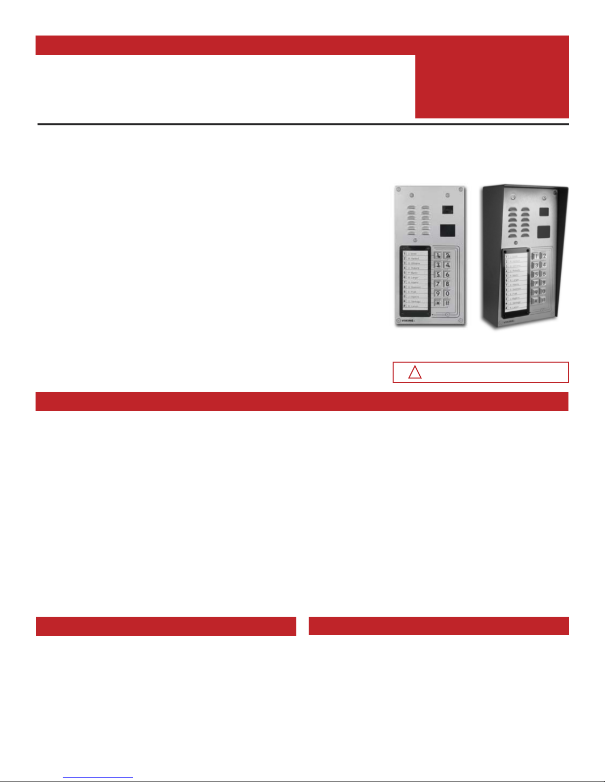
The K-1275-IP is a durable and attractive hands-free phone for apartment and residential door entry
applications requiring a vandal resistant VoIP speaker phone with an integrated 125 KHz Proximity Card
Reader and analog Color Video Camera. The K-1275-IP phone is designed to provide quick and reliable
hands-free communication for SIP VoIP phone systems or cloud based service providers. The unit can be
programmed from any PC on the same LAN or remotely using a Static IP Address. The K-1275-IP entry phone
can dial up to 12 programmable numbers and another 12 rollover numbers. The brushed stainless steel
faceplate has a built-in 12 resident directory with a waterproof, scratch resistant lens and 12 buttons for single
push auto-dialing of a tenant’s phone number or business extension.
When the K-1275-IP phone is connected to an apartment or business tenant, a built-in contact closure may
be activated to control an electric gate or door strike. Up to 1,000 keyless entry codes may be programmed,
providing tenants with keyless entry. The K-1275-IP has a built-in Proximity Card Reader with capacity to
program up to 1,000 card numbers. Keyless entry codes and card numbers can be programmed to only allow
access at specific times and/or day of the week. The K-1275-IP includes a request for exit (REX) input and
also offers event logging with time and date stamp.
The K-1275-IP-EWP shares all of the features of the K-1275-IP in addition to Enhanced Weather Protection
(EWP) for outdoor installations where the unit is exposed to precipitation or condensation. EWP products
feature foam rubber gaskets, sealed connections, gel-filled butt connectors, as well as urethane or thermal
plastic potted circuit boards. For more information on EWP, see DOD# 859.
K-1275-IP
(shown in optional VE-5x10-SS
surface mount box)
• Programmable to speed dial up to 12 numbers
• Cycles to roll over phone number on busy or no-answer
• Program up to 1,000 keyless entry codes and/or proximity card numbers
• Keyless entry codes and proximity card numbers can be programmed to only
allow access at specific times and day of week
• Event logging with time and date stamp
• Optional Enhanced Weather Protection (EWP), EWP products are designed to
meet IP66 Ingress Protection Rating, see DOD# 859
• Hangs up on busy signal, time-out or touch tone command
• Remotely programmable
• Extended temperature range (-40°F to 140°F)
• Programmable volume adjustments for microphone and speaker
• Selectable auto-answer feature for monitoring
• Zinc plated steel rough-in box included
• Optional LRR-4 Long Range RFID Reciever, see DOD #226
• Optional VE-5x10 Surface Mount Box available, see DOD #424
• Optional VE-LIGHT kit to illuminate the front panel at night, see DOD# 428
• Diagnostics (for testing mic, speaker, relays, and proximity cards)
Vandal Resistant VoIP Entry Phone System with Built-In Directory,
Proximity Card Reader, 12 Button Auto Dialer, and Analog Video Camera
K-1275-IP
“Brushed 316 Stainless Steel”
(similar to brushed nickel)
K-1275-IP Series
VoIP Entry Phone System
with Built-In Proximity Card
Reader and Color Camera
August 23, 2017
Installation requires the assistance of a
Network Administrator / IT Technician.
!
www.vikingelectronics.com
• Residential Gate Entrance
• Courtesy Assistance Phone
• Customer Service Phone
• Automated Teller (ATM) Phone
• Kiosk Phone with up to
12 number speed dialing
• Door Entry Phone
• Apartment Entry Phone
• Use with any of Viking’s Proximity Credentials: PRX-C, PRX-C-
ISO, PRX-FOB, and LRT-4 see DOD# 198 and 226.
• Use with LRR-4 Long Range RFID Transmitter DOD# 226

2
Viking VoIP SIP System Compatibility List
NOTE: Exclusion from this list means only that compatibility has not been verified, it does not mean incompatibility.
For detailed configuration instructions for certain vendors below, see Configuring Viking VoIP Phone and SIP
Servers, DOD# 944.
* Note: Not compatible with ShoreTel Ring Group/Hunt Group (unit can be programmed to ring an extension 2 or 3 times then roll to the next number, for
a total of 5 numbers).
** Note: Relay operation commands are Not compatible with Panasonic Phone Systems (Panasonic does not transmit DTMF between station ports).
Known Incompatible System or Service Provider: Ring Central (Requires Authorization ID and Proxy address).
Vendor
Infrastructure Class
Softswitch
PBX Proxy
SBC
(session border
controller)
Service
Provider
3COM VCX X
3CX X
Aastra X
Asterisk X
Atcom X
Avaya Aura Communication Manager X
Avaya IP Office X
BlueBox X
Brekeke X
Callcentric X
Cisco Unified Communications Manager (CUCM) X X
Cisco Unified Communications Manager Express
(CUCME)
X X
Elastix X
Epygi QX200 X
Freeswitch X
Grandstream X
Interactive Intelligence X X
iPECS (Ericsson-LG) X
iptel.org X
Kamailio X X
MetaSwitch XX
NEC X
OfficeSIP X
OpenSIPS X
Panasonic** (with SIP Extension Card) X
Samsung Communications Manager (SCM) X X
ShoreTel* X
Siemens Communications Server (SCS) X
SIP Express Router (SER) X X
sip.antisip.com X
Snom PBX X
Sonus X
Switchvox X X
Teksip X
Toshiba X
VoIP.ms X

3
Image Sensor: 1/4” color CMOS
Video Output: 1 VP-P composite, NTSC, 75 ohms
Resolution: 420 lines (640 x 480 @ 30fps / 307,200 pixels)
Sensitivity: 0.025 LUX (50 IRE) F 1.2 3200K
Lens: 2.1mm, conical pinhole
FOV (Field of View): 80° Horizontal, 60° Vertical, 100° Diagonal
Tilt/Swivel Adjustment: Vertical +/- 20°, horizontal +/- 30° (see Diagram A)
IR Compatibility: This camera is equipped with an OLP (Optical Low Pass) filter to maintain
correct video color in outside applications. The standard camera is NOT compatible with IR
illuminators. If IR illumination is required, you will need to replace the existing camera with a Viking
model VCAM-1IR. For more information, see DOD# 190.
Maximum Wire Run Length: 1000 ft with *RG59/RG6 for video and CAT5 for power (1 pair) and
entry phone audio (1 pair). 150 ft with CAT5E for video, power and entry phone audio (longer
video runs are possible by using video balun transceivers.
* Note: RG59 or RG6 with solid center conductor and 95% bare copper braid shield.
Camera Specifications
Definitions
Client: A computer or device that makes use of a server. As an example, the client might request a particular file from the server.
DHCP: Dynamic Host Configuration Protocol. In this procedure the network server or router takes note of a client’s MAC address and assigns an IP address to allow the client to
communicate with other devices on the network.
DNS Server: A DNS (Domain Name System) server translates domain names (ie: www.vikingelectronics.com) into an IP address.
Ethernet: Ethernet is the most commonly used LAN
technology. An Ethernet Local Area Network typically uses twisted pair wires to achieve transmission speeds up to 1Gbps.
Host: A computer or device connected to a network.
Host Name: A host name is a label assigned to a device connected to a computer network that is used to identify the device in various forms of network communication.
Hosts File: A file stored in a computer that lists host names and their corresponding IP addresses with the purpose of mapping addresses to hosts or vice versa.
Internet: A worldwide system of computer networks running on IP protocol which can be accessed by individual computers or networks.
IP: Internet Protocol is the set of communications conventions that govern the way computers communicate on networks and on the Internet.
IP Address: This is the address that uniquely identifies a host on a network.
LAN: Local Area Network. A LAN is a network connecting computers and other devices within an office or building.
Lease: The amount of time a DHCP
server reserves an address it has assigned. If the address isn’t used by the host for a period of time, the lease can expire and the address can be
assigned to another host.
MAC Address: MAC stands for Media Access Control. A MAC address, also called a hardware address or physical address, is a unique address assigned to a device at the factory. It
resides in the device’s memory and is used by routers to send network traffic to the correct IP address. You can find the MAC address of your K-1775-IP phone printed on a white label
on the top surface of the PoE LAN port.
Router: A device that forwards data from one network to another. In order to send information to the right location, routers look at IP Address, MAC Address and Subnet Mask.
RTP: Real-Time Transport Protocol is an Internet protocol standard that specifies a way for programs to manage the real-time transmission of multimedia data over either unicast or multicast
network services.
Server: A computer or device that fulfills requests from a client. This could involve the server sending a particular file requested by the client.
Session Initiation Protocol (SIP): Is a signaling communications protocol, widely used for controlling multimedia communication sessions such as voice and video calls over Internet
Protocol (IP
) networks. The protocol defines the messages that are sent between endpoints, which govern establishment, termination and other essential elements of a call.
Static IP Address: A static IP Address has been assigned manually and is permanent until it is manually removed. It is not subject to the Lease
limitations of a Dynamic IP Address
assigned by the DHCP Server. The default static IP Address is: 192.168.154.1
Subnet: A portion of a network that shares a common address component. On TCP/IP networks, subnets are defined as all devices whose IP addresses have the same prefix. For example,
all devices with IP addresses that start with 100.100.100. would be part of the same subnet. Dividing a network into subnets is useful for both security and performance reasons. IP networks
are divided using a subnet mask.
TCP/IP: Transmission Control Protocol/Internet Protocol is the suite of communications protocols used to connect hosts on the Internet. TCP/IP uses several protocols, the two main ones
being TCP and IP. TCP/IP is built into the UNIX operating system and is used by the Internet, making it the de facto standard for transmitting data over networks.
TISP: Telephone Internet Service Provider
WAN: Wide Area Network. A WAN is a network comprising a large geographical area like a state or country. The largest WAN is the Internet
.
Wireless Access Point (AP): A device that allows wireless devices to connect to a wired network using Wi-Fi, or related standards. The AP usually connects to a router (via a wired
network) as a standalone device, but it can also be an integral component of the router itself.
Wireless Repeater (Wireless Range Extender): takes an existing signal from a wireless router or access point and rebroadcasts it to create a second network. When two or more hosts
have to be connected with one another over the IEEE 802.11 protocol and the distance is too long for a direct connection to be established, a wireless repeater is used to bridge the gap.
Power: PoE powered from K-1275-IP PCB
Maximum Cable Length: 500 ft 24 Awg stranded shielded (Belden 9537)
Frequency: 125KHz
Format: 26 bit Wiegand
Read Range: 1.25” to 2.0”
Technologies Supported: Viking PRX-C, PRX-C-ISO, PRX-FOB, LRT-4, certain legacy
HID® proximity protocols* and certain AWID 125Khz proximity protocols**
Transducer: Beeps during card read
LED: Red, turns off during card read
Humidity: Up to 100% (fully potted EWP)
Operating Temperature: -34° C to 65° C (-30° F to 150° F)
* HID and the HID logo are registered trademarks of HID Global Corporation, an ASSA
ABLOY company. All other trademarks are the property of their respective owners.
** AWID is a trademark of Applied Wireless Identification Group.
Proximity Card Reader Specifications
Diagram A
Camera Horizontal Field of View:
80° Lens FOV
Rotate
Left 30°
Camera Lens
Rotate
Right 30°
4
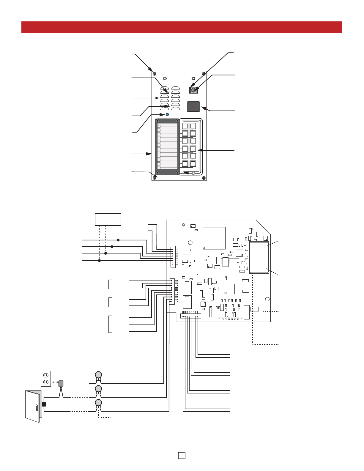
Features Overview
Note: The gel-filled (water-tight) butt connectors are designed for insulation displacement on 19-26 gauge wire with a maximum insulation of 0.082 inches.
Keypad: Push to initiate call, push again to
disconnect. Zinc Die cast with Satin Chrome
Finish, internally sealed per IP67.
Speaker Screen: Speaker screen with 0.018"
wide slots to prevent punctures from paperclips,
etc.
Faceplate Material: 14 gauge 316 stainless steel
with #4 brushed finish.
Speaker: Mylar speaker with rubber gasket to
maintain water-tight seal and eliminate water
deterioration.
Blue Call LED: Lights steady when idle, flashes
during dialing, then lights steady when answered.
Microphone: Omni-directional microphone with
protective water-resistant cloth.
Front View of the
K-1275-IP Entry Phone
Condensation Drain Hole
Mounting Screws:
(4) 6-32 X 3/4” Marine grade
316 stainless steel, flat head, T-10 Torx security
screws and drive bit (included).
Laser Etched Graphics: For long lasting easy to
read graphics.
VIKING
©
1
2
3
4
5
6
7
8
9
0
#
*
#
0
9
8
6
5
3
2
12
34
5
6
78
9
0
#
*
Color Video Camera: Wide operating
temperature range of -40°F to 140°F, NTSC
composite video output with 420 lines of
resolution, 80° wide viewing angle lens, tilt and
swivel adjustments for aiming towards visitors.
Protective Camera Window: Impact resistant
polycarbonate lens with scratch resistant
coating and water-tight gasket.
Proximity Card Reader: 26-bit Wiegand,
125KHz, red LED turns off and transducer will
beep during card read. Fully potted EWP. Read
range 1.25" to 2.0". Impact resistant
polycarbonate lens with water-tight gasket.
Optional: Connect to an additional
Long Range RFID Receiver with 26
Bit Wiegand Output (Viking Model
PRX-3 or LRR-4 See DOD# 228 or
226)
Proximity Card
Reader (26 Bit
Wiegand Input)
VE-LIGHT, etc.
White
Green
+ Red
- Black
12 VDC Power Output for
(12VDC @ 50mA max)
Request for Exit
(REX) Input
Relay 2 Output Contacts
(2A@30VDC/ 250VAC max)
Optional
Long Range
RFID Receiver
- Black
Green
Green
+ Red
COM.
Connect to Optional
Doorstrike, Mag Lock,
Gate Controller, etc.
120V AC
connected)
(not
Output Contacts
(2A@30VDC/ 250VAC max)
N.C. (Gray)
Doorstrike /
Magnetic Lock
(Power typically not
required for gate controllers)
COM. (Blue)
N.O. (Yellow)
3 Gel-Filled Butt
Connectors (included)
Camera
Power
- Black
+ Red
Brown
N.C.
Violet
White
N.O.
Relay 1
Rear (PCB) View of K-1275-IP
White
White
+ Red
- Black
- Black
+ Red
Black
Black
MAC:
18E80FXXXXXX
Speaker
LED
Microphone
Call Switch
PoE LAN Port 10/100,
PoE Class 2 (<6.5 Watts):
Connect to your LAN via
RJ45 plug and CAT5 or
greater twisted pair wire.
asdesaxtff
MAC Address Label: The
MAC address is aunique
12 digit number used by
routers to send network
traffic to the correct IP
address.
Yellow Network Status
LED: Lights steady to
indicate power and data
link. Blinks to indicate
network activity.
Green Unit Status LED
5
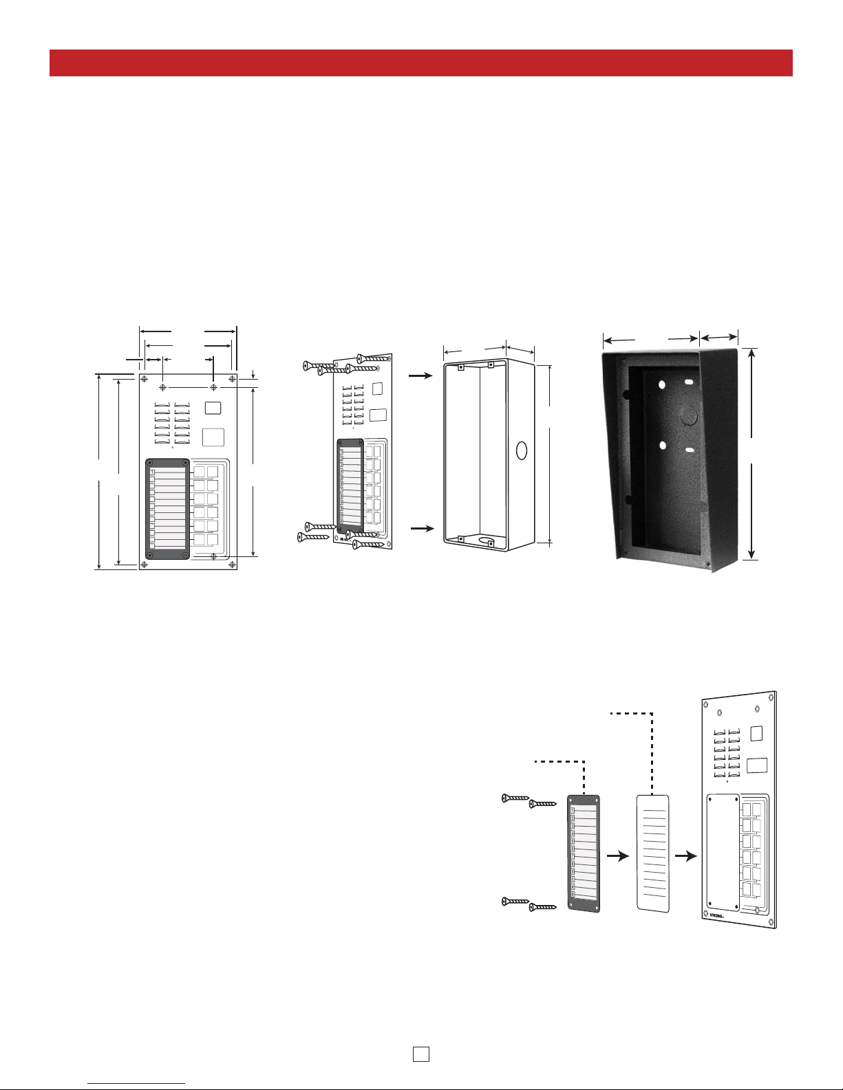
Installation and Mounting
VIKING
©
1
2
3
4
5
6
7
8
9
0
#
*
#
9
8
6
3
2
Optional VE-5x10 Surface Mount
Box (not included), see DOD# 424
10.0"
9.5"
4.50"
2.596"
5.00"
8.65"
0.425"
0.952"
Front View
of the K-1275-IP
9.12"
2.5"
4.5"
Zinc-Plated Steel
Rough-In Box
(included)
Side View
of the K-1275-IP
(8) #6-32 x 3/4" Stainless
Steel, T-10 Torx Security
Screws with drive bit
(included)
14 Gauge Marine
Grade 316 Stainless
Steel Faceplate
10.14"
3.69"
5.22"
- OR -
A. Mounting
The K-1275-IP is designed to be installed in a sheltered location, and is not meant to be used outdoors. For outdoor
applications use the K-1275-IP-EWP. The K-1275-IP can either be installed as a flush mount unit using the included
rough in box, or as a surface mount unit using an optional VE-5x10 or VE-5x10-SS. The rough in box uses the inner
set of four holes on the face plate while the VE-5x10 uses the outside set of holes. A set of dummy screws and nuts are
provided to fill the unused mounting holes.
NOTE: Write down the MAC Address (found on the RJ-45 jack) as this may be needed to identify the unit after installation.
B. Changing the Directory
To install a directory, remove the four screws that
mount the directory lens to the front of the K-1275-IP
using the included Allen wrench. Insert a paper
directory behind the lens and secure the two back onto
the front panel being careful to align the names with
the front panel graphics.
Note: To print directory forms for the K-1275-IP, go to
www.vikingelectronics.com and enter “930” in the DOD
field at the top of the page for a direct link to the PDF.
5
7
0
Paper Directory
Directory
Lens
6
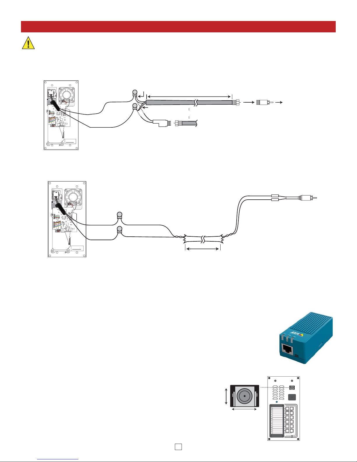
Camera Wiring and Adjustments
A. Using RG59 for Analog Video (Recommended)
Yellow (Video)
3-Wire Gel-Filled Butt
Connectors included
(3M Scotchlok UR2)
Back View of the K-1275-IP
To unused input on TV,
VHF modulator, whole
house video distribution
equipment, IP video
encoder (Axis M7001), etc.
* RG59 or RG6 Shielded
Video Cable, up to 1000 ft
Center conductor
stripped back 5/8"
Twisted foil and braided shield
"F"
Connector
"F" to Phono Plug
Adapter
(Radio
Shack part #278-252)
- Black (GND)
OR
Black
Yellow/Red
** Female "F" to Wire or "BNC" to Wire
Converter Cable (not included)
VIKING
Model:
xxxxxxxxx
P/N: xxxxxxxxx
S/N: XXXXXX
Viking Electronics, Inc. (715)386-8861
1531 Industrial St., Hudson, WI 54016
DEV:
RoHS
J6
Q17
1
570
8
2W
J6
MAC:
18E80FXXXXXX
asdesaxtff
IMPORTANT: Electronic devices are susceptible to lightning and power station electrical surges from the AC outlet.
It is recommended that a surge protector be installed to protect against such surges.
* Note: RG59 or RG6 with solid center conductor and 95% bare copper braid shield.
** Note: For ease of installation, a Viking Female "F" to
Wire Converter Cable can be used (Part # 261217) or
"BNC" to wire converter cable (Part # U213510) can be
used. Go to www.vikingelectronics.com and click on
"Spare Parts" to order.
B. Using CAT5E or CAT6 for Analog Video (see Caution below)
Video GND (-) Green
Video Out (+) W/G
* Up to 150 ft
3-Wire Gel-Filled Butt
Connectors included
(3M Scotchlok UR2)
CAT5E or
CAT6 Cable
(see Caution below)
Phono (RCA) Plug,
F Connector, Etc.
(+)
(-)
To unused input on TV, VHF
modulator, whole house video
distribution equipment, IP video
encoder (Axis M7001), etc.
Video Out (+)
Video GND (-)
W/G Green
Back View of the K-1275-IP
VIKING
Model:
xxxxxxxxx
P/N: xxxxxxxxx
S/N: XXXXXX
Viking Electronics, Inc. (715)386-8861
1531 Industrial St., Hudson, WI 54016
DEV:
RoHS
J6
J6
MAC:
18E80FXXXXXX
asdesaxtff
* Note: Up to 150 ft video cable run length can be achieved using CAT5E or CAT6 cable. Longer cable runs can be used if a passive or active video Balun
transceiver is used on each end of the cable. Generally, passive transceivers can achieve up to 750 ft cable runs where active transceivers can achieve up to
3000 ft runs depending on cable type, etc. The type of video balun transceiver required is specific to your cable run length. For more information on video balun
transceivers go to: www.northernvideo.com.
Caution: When routing CAT5E or CAT6 cable, maintain a minimum distance of 3 ft from any parallel high voltage wire (110 VAC) and a minimum of 2 ft from
crossing any high voltage wire. For installations where RF noise is expected (commercial applications) or wire runs are near high voltage (110 VAC) wires, a
shielded video cable such as RG6 is recommended.
C. Using a Video Encoder to Convert the Analog NTSC Video to IP
D. Adjusting the Camera
Axis manufactures video servers that encode analog video signal for transmission across IP
network or the internet. The single channel model M7011 is shown. Supplied software allows
you to access Axis units connected to the network (auto-discovery) and program them via a
web page interface. The video can then be monitored from any location on the network.
For more information, go to www.axis.com
The camera can be tilted and rotated to your desired
position. A portable service (test) monitor can be used
to determine the correct viewing angle during
installation.
Important: To prevent the edge of the faceplate from
being viewed in the video image, do not rotate the
camera beyond 30 degrees or tilt beyond 20 degrees.
#
0
9
8
6
4
3
Axis Model
M7011 shown
Vertical (Tilt)
Adjustment
+/- 20 degrees
maximum
Horizontal (Rotation)
Adjustment
+/- 30 degrees maximum
1
2
3
4
5
5
6
7
8
9
0
*
#
VIKING
12
34
5
6
78
0
9
#
*
©
7
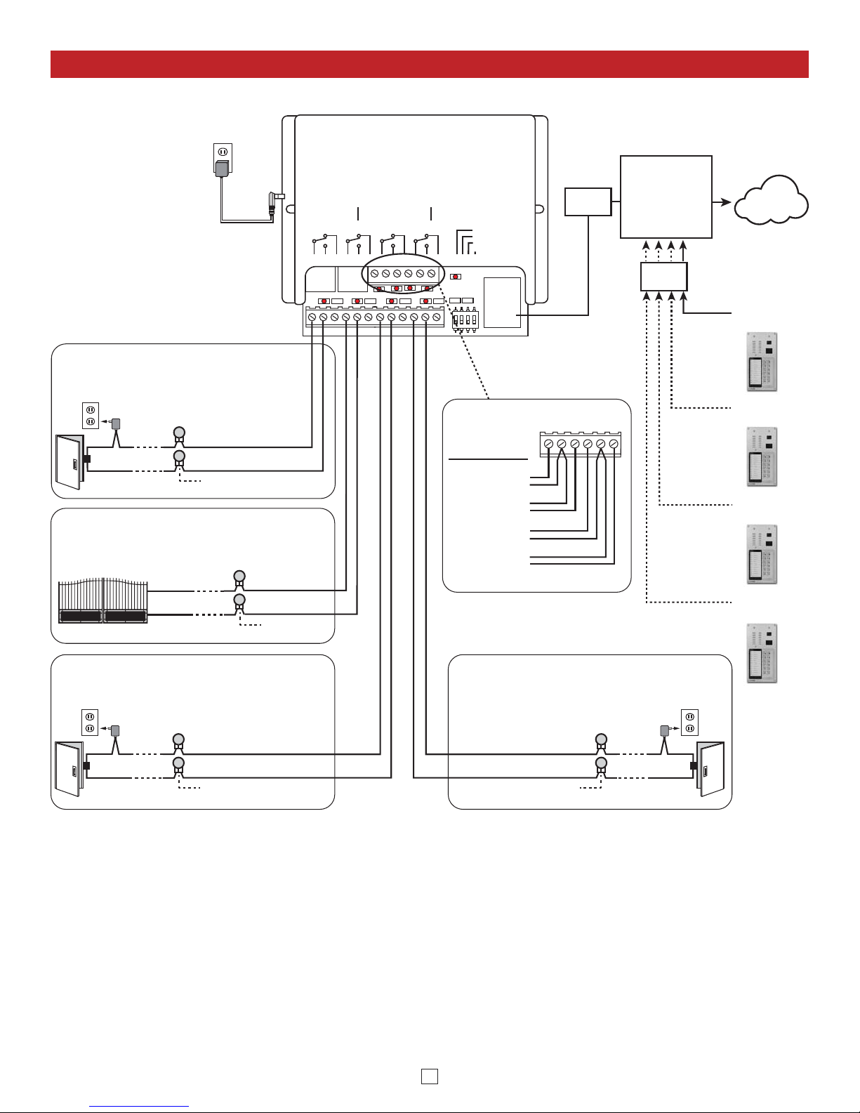
Using a Viking Model RC-4A for Secure Remote Relay Control
Switch
SIP VoIP PBX,
SIP Cloud based
Service Provider
or
PC with SIP
Server Software
Internet
PoE
Switch
LED 8
LED 7LED 6
LED 4
LED 3
LED 2
LED 1
LED 5
LED 9
123on4
1234
VIKING
ELECTRONICS
HUDSON, WI 54016
NETWORK ENABLED
RELAY CONTROLLER
MODEL RC-4A
©
VIKING
1
IN1 C IN2 IN3 C IN4
23456
POWER 12V DC
RE LAY 1 RE LAY 2 RE LAY 3 REL AY 4
1
2
3
4
5
7
8
9
10
11
12
STATUS
LED
6
NETWORK
LOGIC LEVEL
PROGRAMMING
RESTORE DEFAULTS
SPARE
12V DC Adapter
(included)
Sensor
Examples:
Door Sensor
Gate Sensor
Door Sensor
Door Sensor
N.O.
COM.
Connect to Doorstrike,
Mag Lock, Gate Controller, etc.
2 Gel-Filled Butt
Connectors (included)
Doorstrike /
Magnetic Lock
120V AC
Door / Gate Examples:
Door near Entry Phone 1
N.O.
COM.
2 Gel-Filled Butt
Connectors (included)
(Power typically not
required for gate controllers)
Gate Controller
K-1275-IP
Entry Phone 1
K-1275-IP
Entry Phone 2
K-1275-IP
Entry Phone 3
K-1275-IP
Entry Phone 4
Relay 2 Output Contacts (5A@30VDC / 250VAC max)
Connect to Gate Controller, etc.
Gate near Entry Phone 1
N.O.
COM.
2 Gel-Filled Butt
Connectors (included)
Doorstrike /
Magnetic Lock
120V AC
Door near Entry Phone 2
N.O.
COM.
Relay 4 Output Contacts (5A@30VDC /
250VAC max) Connect to Doorstrike,
Mag Lock, Gate Controller, etc.
2 Gel-Filled Butt
Connectors (included)
Doorstrike /
Magnetic Lock
120V AC
Door near Entry Phone 3
1
IN1 C IN2 IN3 C IN4
23456
Relay 1 Output Contacts (5A@30VDC / 250VAC max)
Connect to Doorstrike,
Mag Lock, Gate Controller, etc.
Relay 3 Output Contacts (5A@30VDC / 250VAC max)
The front panel of the K-1275-IP is mounted using security Torx screws to help prevent intruders from removing the panel
and accessing the on board door strike/gate control relays. For applications requiring additional security, a Viking model
RC-4A remote relay controller can be used. The relay controller is mounted securely inside the building and connected to
the same LAN as the K-1275-IP. The on board door strike relays would not be used in this case as the K-1275-IP will send
an encrypted message to the RC-4A to activate its relays which control the door strikes/gates. For more information, see
DOD# 582 at www.VikingElectronics.com.
Up to 4 K-1275-IP’s can communicate with one RC-4A allowing you to securely control four entrances.
When using an RC-4A for remote relay control the K-1275-IP’s relays should be set to “External” in the PC programming.
Note: If the K-1275-IP loses communications with the RC-4A, the LED on the front panel of the K-1275-IP will flash 3 times
every 2 seconds indicating the communication error. If this error occurs, make sure the RC-4A is powered, has a network
connection and has the correct IP address and security code of the K-1275-IP displaying errors.
 Loading...