

Viking E-1600-20A/EWP, E-30-PT/EWP, E-1600-30A/EWP, E-1600A-BLT2-EWP, K-1200/EWP Product Manual
...
PRODUCT MANUAL
Designed, Manufactured and Supported in the USA
COMMUNICATION & SECURITY SOLUTIONS
Add Panel Lighting to Your
Viking Doorbox or Entry Phone
Applications
The VE-LIGHT kit adds bright LED illumination to
any doorbox or entry phone that is housed in a
Viking VE-5x5, VE-6x7 or VE-5x10 enclosure. It
can also be used on Viking’s E-1600A-BLT-EWP
tower phone.
The stainless steel bracket is easily mounted using
existing holes and hardware. Two bright white
LEDs are used as the light source, so there are no
filaments to break or bulbs to burn out.
If used with the W-1000, W-3000 or W-3005, the
VE-LIGHT can be wired directly to the AC power
input of the doorbox, or use the included 12 volt
power supply. Any power source between 12 and
24 volts, AC or DC can be used to supply the VE-
LIGHT with power.
• Ultra bright LEDs for long life
• Easy retro-fit to existing entry phones
• Can use the same power source as doorbox
• Can be powered from 12 to 24 volts AC or DC
Power: 120V AC/12V DC 500mA, UL listed
adapter provided or use any 12-24V AC or DC
source @ 50mA
Dimensions: 5” x 3” x 1”(127mm x 8mm x 25mm)
Environmental: -15°F to 130°F (-26°C to 54°C)
with 5% to 95% non-condensing humidity
Shipping Weights: 1 lb (0.45 kg)
Maximum Power Run: 1000 ft (304m) using 24
AWG wire
Material: 24 gauge Marine Grade 316 stainless
steel
VE-LIGHT
Enclosure Lighting
Kit
December 20, 2016
Features
Specifications
www.vikingelectronics.com
Information: (715) 386-8861
VIKING
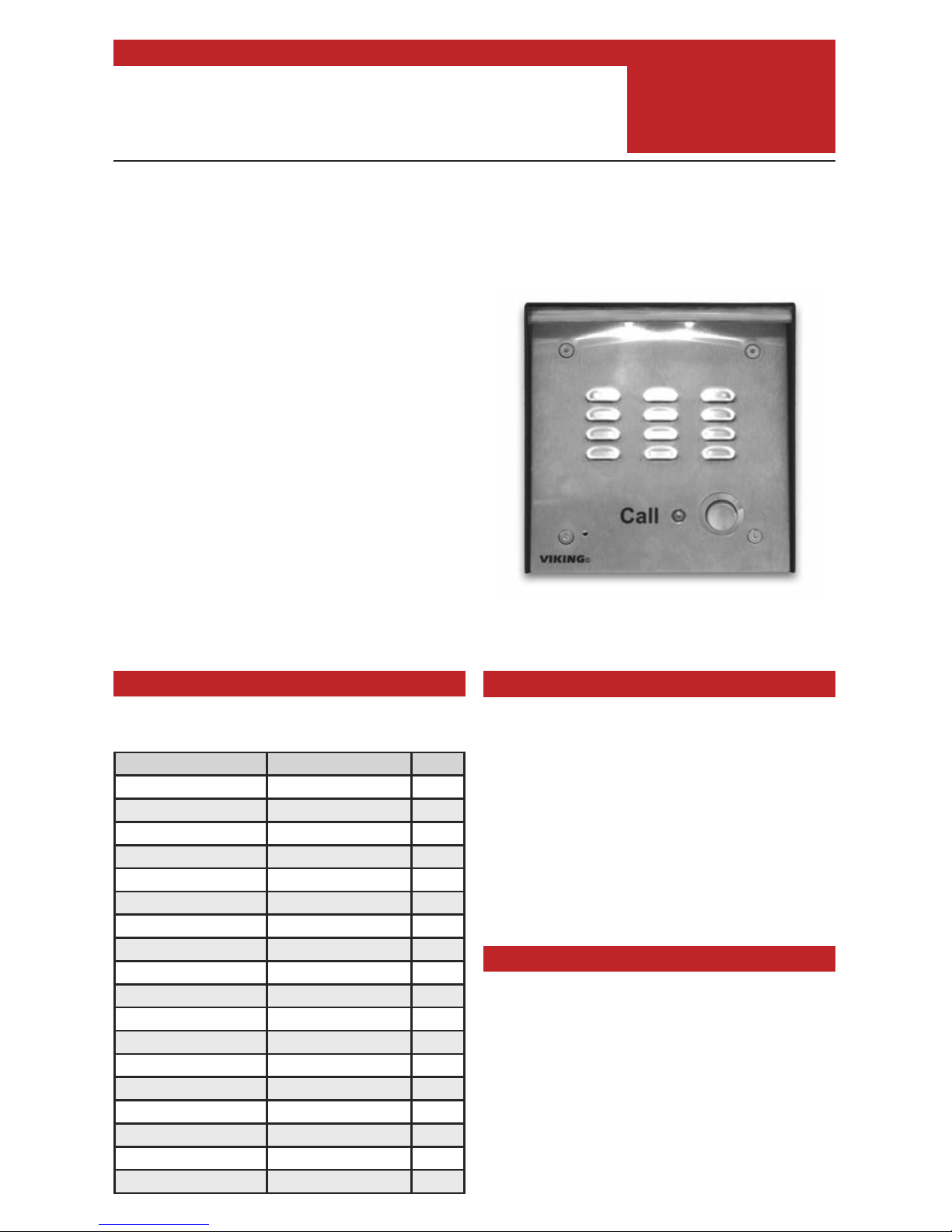
VE-LIGHT shown above with Viking W-3000
and VE-5x5 (not included)
Viking Model VE Model DOD#
E-10A/EWP VE-5X5 / SS 210
E-30/EWP VE-5X5 / SS 212
E-30-PT/EWP VE-5X5 / SS 214
E-35/EWP VE-5X5 / SS 178
E-1600-20A/EWP VE-5X5 / SS 215
E-1600-30A/EWP VE-5X5 / SS 215
E-1600A-BLT-EWP (included) 217
E-1600A-BLT2-EWP (included) 217
K-1200/EWP VE-5x10 / SS 182
K-1205/EWP VE-5x10 / SS 183
K-1500-7 VE-5x10 / SS 352
K-1700-3/EWP VE-6x7 / SS 157
K-1705-3/EWP VE-6x7 / SS 159
K-1900-7/EWP VE-5x10 / SS 364
K-1900-8/EWP VE-5x10 / SS 362
W-1000/EWP VE-5X5 / SS 170
W-3000/EWP VE-5X5 / SS 180
W-3005/EWP VE-5X5 / SS 181
• The VE-LIGHT is designed to be used in conjunction with the following Viking products
Installation
IMPORTANT: Electronic devices are susceptible to lightning and power station electrical surges from both the AC
outlet and the telephone line. It is recommended that a surge protector be installed to protect against such surges.
Step 1
When using the power terminals, make sure your product is listed in Diagram 1. If your product is not
listed please see section B below and wire using the included power supply.
Step 2 Disconnect power from the doorbox or phone.
Step 3 Remove the doorbox or phone from the surface mount box.
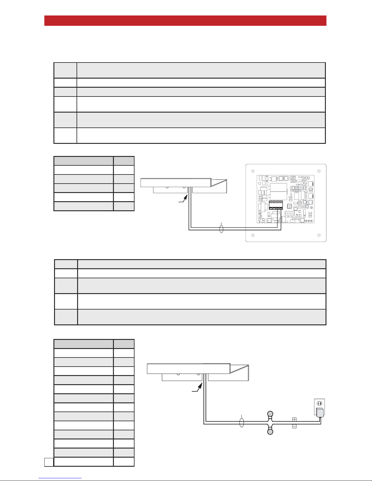
Step 4
Connect the two wires from the VE-LIGHT to the power input terminals of the doorbox (see Diagram
2). Note: Wires can be connected in either polarity.
Step 5
Place the VE-LIGHT bracket against the upper mounting lip of the surface mount box and route wires
through the provided slot (see Diagram 2).
Step 6
Carefully place the phone or doorbox back into the surface mount box, making sure the wires stay in
the slot (see Diagram 5).
B. Using the Included Power Supply (see Diagram 3)
A. Using the Power Input Terminals of a Viking Doorbox
Diagram 1
Viking Model DOD#
K-1200/EWP 182
K-1205/EWP 183
W-1000/EWP 170
W-3000/EWP 180
W-3005/EWP 181
Viking Model DOD#
E-10A/EWP 210
E-30/EWP 212
E-30-PT/EWP 214
E-35/EWP 178
E-1600-20A/EWP 215
E-1600-30A/EWP 215
E-1600A-BLT-EWP 217
E-1600A-BLT2-EWP 217
K-1500-7 352
K-1700-3/EWP 157
K-1705-3/EWP 159
K-1900-7/EWP 364
K-1900-8/EWP 362
Diagram 3
Step 1 Disconnect power from the doorbox or phone.
Step 2 Remove the doorbox or phone from the surface mount box.
Step 3
Connect the two wires from the VE-LIGHT to the included power supply using the included butt connectors (see Diagram 4). Note: Wires can be connected in either polarity.
Step 4
Place the VE-LIGHT bracket against the upper mounting lip of the surface mount box and route wires
through the provided slot (see Diagram 4).
Step 5
Carefully place the phone or doorbox back into the surface mount box, making sure the wires stay in
the slot (see Diagram 5).
Rear View of Viking Doorbox
(not included)
Not polarity
sensitive
Front View of the VE-LIGHT
IMPORTANT:
Wires MUST be
routed through
the provided slot.
Diagram 2
Front View of the VE-LIGHT
IMPORTANT:
Wires MUST be
routed through
the provided slot.
* (2) Gel-Filled
Butt Connectors
(included)
Not polarity
sensitive
120V AC
12V DC
Adapter
(included)
Negative
Positive
Diagram 4
* Note: The gel-filled (water-tight) butt connectors are designed for insulation displacement on 19-26 gauge wire with a maximum insulation of
0.082 inches. Do not strip wires prior to terminating.
2

C. Mounting with a Surface Mount Box and Phone or Doorbox
Phone or
Doorbox
(E-30 shown,
not included)
Surface Mount Box
(VE-5x5 shown,
not included)
VE-LIGHT
Call
Diagram 5
Related Products
3
Surface Mount Viking Products While Maintaining Weather and Vandal Resistance
The VE-5x5, VE-6x7 and VE-5x10 add vandal
and weather resistance, as well as versatility to
many Viking products. The VE-Series back-
boxes are available in black fine texture powder
painted steel or Marine Grade 316 stainless
steel. The weather resistant boxes are designed
to be surface mounted to a wall, post, single
gang box, or a VE-GNP gooseneck pedestal.
The VE-5x5 is designed to be used with the E-10A-EWP, E-30-
EWP, E-30-PT-EWP, E-60-EWP, E-65-EWP, E-70-EWP, E-75EWP entry phones, the E-1600-20A-EWP and E-1600-30A-EWP
emergency phones, as well as the W-1000-EWP and W-3000-
EWP handsfree doorboxes. The VE-6x7 is designed to be used
with the K-1700-3-EWP and K-1705-EWP entry phones and the
VE-5x10 is designed to be used with the K-1900-7-EWP and the
K-1900-8-EWP vandal resistant phones.
The VE-GNP gooseneck pedestals are designed to be used with
the VE-5x5, VE-6x7 and VE-5x10 backboxes and are ideal for
drive up communications. The VE-PNL’s are VE-Series back-
boxes with a blank aluminum panel. The user can customize the
clear-coated aluminum panel to mount a PRX-1 card reader, PRX-
2 keypad or switch. The kits come complete with box, gasket,
panel and screws. Model numbers that end with “SS” are stainless
steel version. Note: The use of magnets to mount the VE-Series
enclosure to a metal surface can affect the operation of the enclosed product.
For more information
see DOD# 424

Printed in the U.S.A.DOD# 428
ZF301930 Rev C
Due to the dynamic nature of the product design, the information contained in this document is subject to change without notice. Viking Electronics, and its affiliates
and/or subsidiaries assume no responsibility for errors and omissions contained in this information. Revisions of this document or new editions of it may be issued
to incorporate such changes.
Product Support: (715) 386-8666
IF YOU HAVE A PROBLEM WITH A VIKING PRODUCT, CONTACT: VIKING TECHNICAL SUPPORT AT (715) 386-8666
Our Technical Support Department is available for assistance Monday 8am - 4pm and Tuesday through Friday 8am - 5pm central time. So
that we can give you better service, before you call please:
1. Know the model number, the serial number and what software version you have (see serial label).
2. Have your Product Manualin front of you.
3. It is best if you are on site.
RETURNING PRODUCT FOR REPAIR
The following procedure is for equipment that needs repair:
1. Customer must contact Viking's Technical Support Department at 715-386-8666 to obtain a Return Authorization (RA) number. The cus-
tomer MUST have a complete description of the problem, with all pertinent information regarding the defect, such as options set, conditions,
symptoms, methods to duplicate problem, frequency of failure, etc.
2. Packing: Return equipment in original box or in proper packing so that damage will not occur while in transit. Static sensitive equipment
such as a circuit board should be in an anti-static bag, sandwiched between foam and individually boxed. All equipment should be wrapped
to avoid packing material lodging in or sticking to the equipment. Include ALL parts of the equipment. C.O.D. or freight collect shipments cannot be accepted. Ship cartons prepaid to: Viking Electronics, 1531 Industrial Street, Hudson, WI 54016
3. Return shipping address: Be sure to include your return shipping address inside the box. We cannot ship to a PO Box.
4. RA number on carton: In large printing, write the R.A. number on the outside of each carton being returned.
RETURNING PRODUCT FOR EXCHANGE
The following procedure is for equipment that has failed out-of-box (within 10 days of purchase):
1. Customer must contact Viking’s Technical Support at 715-386-8666 to determine possible causes for the problem. The customer MUST
be able to step through recommended tests for diagnosis.
2. If the Technical Support Product Specialist determines that the equipment is defective based on the customer's input and troubleshooting,
a Return Authorization (R.A.) number will be issued. This number is valid for fourteen (14) calendar days from the date of issue.
3. After obtaining the R.A. number, return the approved equipment to your distributor, referencing the R.A. number. Your distributor will then
replace the Viking product using the same R.A. number.
4. The distributor will NOT exchange this product without first obtaining the R.A. number from you. If you haven't followed the
steps listed in 1, 2 and 3, be aware that you will have to pay a restocking charge.
Warranty
4
TWO YEAR LIMITED WARRANTY
Viking warrants its products to be free from defects in the workmanship or materials, under normal use and service, for a period of two years
from the date of purchase from any authorized Viking distributor. If at any time during the warranty period, the product is deemed defective or
malfunctions, return the product to Viking Electronics, Inc., 1531 Industrial Street, Hudson, WI., 54016. Customer must contact Viking's Technical
Support Department at 715-386-8666 to obtain a Return Authorization (R.A.) number.
This warranty does not cover any damage to the product due to lightning, over voltage, under voltage, accident, misuse, abuse, negligence
or any damage caused by use of the product by the purchaser or others. This warranty does not cover non-EWP products that have been
exposed to wet or corrosive environments. This warranty does not cover stainless steel surfaces that have not been properly maintained.
NO OTHER WARRANTIES
. VIKING MAKES NO WARRANTIES RELATING TO ITS PRODUCTS OTHER THAN AS DESCRIBED ABOVE
AND DISCLAIMS ANY EXPRESS OR IMPLIED WARRANTIES OR MERCHANTABILITY OR FITNESS FOR ANY PARTICULAR PURPOSE.
EXCLUSION OF CONSEQUENTIAL DAMAGES
. VIKING SHALL NOT, UNDER ANY CIRCUMSTANCES, BE LIABLE TO PURCHASER,
OR ANY OTHER PARTY, FOR CONSEQUENTIAL, INCIDENTAL, SPECIAL OR EXEMPLARY DAMAGES ARISING OUT OF OR RELATED
TO THE SALE OR USE OF THE PRODUCT SOLD HEREUNDER.
EXCLUSIVE REMEDY AND LIMITATION OF LIABILITY
. WHETHER IN AN ACTION BASED ON CONTRACT, TORT (INCLUDING NEGLIGENCE OR STRICT LIABILITY) OR ANY OTHER LEGAL THEORY, ANY LIABILITY OF VIKING SHALL BE LIMITED TO REPAIR OR REPLACEMENT OF THE PRODUCT, OR AT VIKING'S OPTION, REFUND OF THE PURCHASE PRICE AS THE EXCLUSIVE REMEDY AND
ANY LIABILITY OF VIKING SHALL BE SO LIMITED.
IT IS EXPRESSLY UNDERSTOOD AND AGREED THAT EACH AND EVERY PROVISION OF THIS AGREEMENT WHICH PROVIDES
FOR DISCLAIMER OF WARRANTIES, EXCLUSION OF CONSEQUENTIAL DAMAGES, AND EXCLUSIVE REMEDY AND LIMITATION OF
LIABILITY, ARE SEVERABLE FROM ANY OTHER PROVISION AND EACH PROVISION IS A SEPARABLE AND INDEPENDENT ELEMENT
OF RISK ALLOCATION AND IS INTENDED TO BE ENFORCED AS SUCH.
 Loading...