


Use/Install
GUIDE
Under-counter
Micro Green & Herb Cabinet
GCV12

TABLE OF CONTENTS
FEATURES AND SPECIFICATIONS 3
UNPACKING AND INSPECTION 4
SAFETY PRECAUTIONS 5-6
INSTALLATION & STARTUP 6-11
PROGRAMMING 12-13
SETTING UP YOUR GROWING CYCLES 14
FUNCTIONS OF THE ZONE SCREEN 14
FUNCTIONS OF THE MAIN RESERVOIR SCREEN 14
PLANTING & GROWING 15
GROWING GUIDE 16
GROWING DO’S AND DON’TS 17
CLEANING AND MAINTENANCE 18-19
PERIODIC MAINTENANCE PROCEDURES 20
REPLACING THE LIGHTS 21
SANITATION AND FOOD SAFETY 22
FREQUENTLY ASKED QUESTIONS & TROUBLESHOOTING 23
MICRO GREEN PROBLEMS 24
RESOURCES 25-26
REPLACEMENT PARTS, WIRING & PLUMBING DIAGRAMS 27-28
SERVICE INFORMATION 30
WARRANTY 31
TABLE OF CONTENTS
2
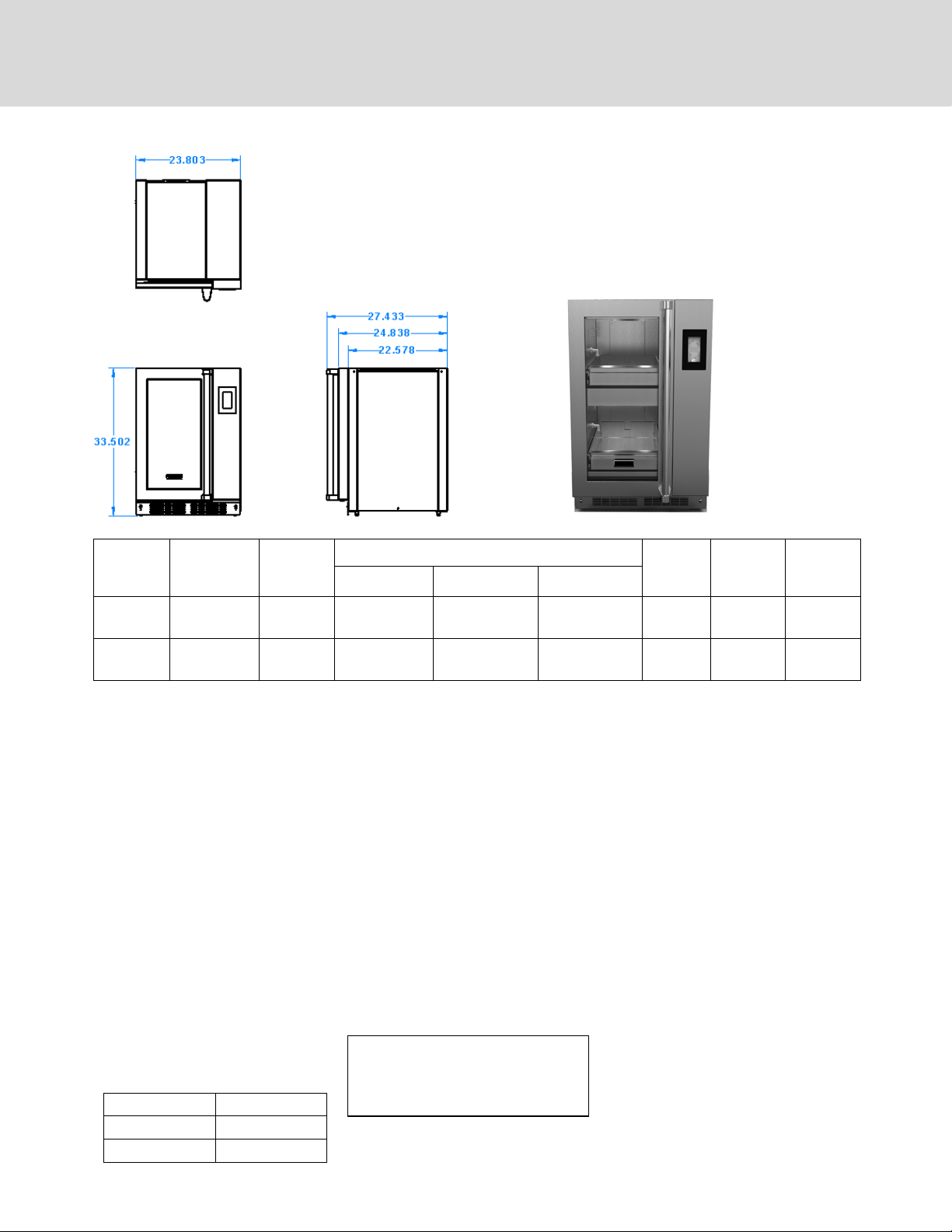
FEATURES AND SPECIFICATIONS
Your Viking Range, LLC Micro Green & Herb Cabinet provides a self-contained
environment that is ideal for growing herbs, micro greens and even edible owers.
The lights produce the proper spectrum and an irrigation system delivers water and
nutrients to the plants. The automated system provides everything the plants need
to grow year round and right in the kitchen. It is preprogrammed for the growing
needs for common herbs and micro greens. You can customize the growing
conditions for other plants as needed.
GCV12LSS
Model
Number
Number of
Growing
Zones
Capacity
10”x20”
Trays
Overall Dimensions Door
Height Depth Width
Hinge
Location
Adjustable
Leg
Height
GCV12RSS 2 2 33-1/2 (851 mm) 24-7/8” (632 mm) 23-7/8 (607 mm) Right 1-1/8
(28.6 mm)
GCV12LSS 2 2 33-1/2 (851 mm) 24-7/8” (632 mm) 23-7/8 (607 mm) Left 1-1/8
(28.6 mm)
CONSTRUCTION...Welded & riveted double wall, non-insulated cabinet construction.
CABINET MATERIAL... 430 series stainless
steel exterior; 301 series interior with reective nish
BASE FRAME... 18 gauge stainless steel full
depth bolsters.
LEGS…2.5” Adjustable leveling bolts
DOORS...Double panel tempered glass
door with integrated gasket. Full length
door handle. GCV12RSS hinged on right;
GCV12LSS hinged on left.
GROWING DRAWERS... Removable growing drawers. Stainless steel construction
with drainage holes in rear for ebb and ow
irrigation. Each drawer will accommodate
one standard 10” x 20” at with 5” or 7”
greenhouse dome for sprouting. Includes
one set of growing trays and 5” domes.
Level Growing Space
1 (top shelf) 10.125”
2 10.125”
CONTROLS...Touchscreen digital controls.
Automated system provides correct
measures of water, nutrients, relative humidity, lighting on optimum cycle for plant
growth and nutrient data. Preprogrammed
default settings for most growing needs;
programmable for other growing situations. Lock-out access code.
ENVIRONMENT... Digital controls for automatic light, watering schedule and humidity levels for growing. Temperature based
on ambient room temperature.
WATERING SYSTEM... Automatic ltered
pump/aerator irrigation system delivers
water and nutrients from the reservoir to
the plants. Programmable watering cycle.
Auto-ll reservoir. 3/8” NPT ll connection:
3/8” NPT drain connection. pH and TDS
(total dissolved solids) sensors.
Default Programs:
Watering Cycle: Once every 4 days
Watering Time: 5 Minutes
Daylength: 18 Hours (lights on each day)
GROWING LIGHTS... Equipped with 18” T5
high output uorescent light xtures. Each
xture includes an integrated electronic
ballast, 6400°K lamp with a nano-tech reector for maximum reection. Lights imitate the suns’ rays for optimum growing.
Removable opaque polycarbonate shields.
Fully programmable light cycles.
ELECTRICAL CHARACTERISTICS...
GCV12: operates on 120 volts, 1.6 amps, 60
cycle, single phase. Junction box provided
for hardwiring of unit or a power cord kit
may be purchased and installed in order to
plug unit into existing outlet.
ACCESSORIES/OPTIONS...
Starter kit: includes growing trays,
mats, domes, sifter, pH & TDS calibration solutions, hydrogen peroxide, 20
gallon plastic tub, measuring syringe
Power cord kit: includes one 6’ power
cord with a NEMA 5-15P molded plug
cap; cord grip; wire nuts.
Shipping
Weight
150 (68kg)
150 (68kg)
3
UNPACKING AND INSPECTION
This appliance
should be
thoroughly
cleaned prior to
use. See the CLEANING
INSTRUCTIONS in this
manual.
1. Remove the cabinet from shipping carton, ensuring that all packing materials
and protective plastic has been removed from the unit.
2. Inspect all components for completeness and condition.
3. If any freight damage is present, a freight claim must be led immediately with
the shipping company.
4. Freight damage is not covered under warranty.
NOTE: DO NOT discard the
carton or other packing materials until you have inspected the appliance for hidden
damage and checked it for
proper operation.
5. Check to insure all components are included: cabinet, instruction packet and
additional accessories.
6. Read operation instructions completely.
7. Appliance should be thoroughly cleaned before use. See CLEANING
INSTRUCTIONS in this manual (pages 17-18).
Refer to SHIPPING DAMAGE
CLAIM PROCEDURE on
bottom of this page.
CAUTION: Health and safety regulations vary by jurisdiction. Prior to installation, operator must be aware and must
adhere to all local and state codes, including proper installation, plumbing and electrical hook up, as well as any health
certicates that may be required when growing food in your establishment. Viking Range, LLC assumes no responsibility
for improper installation or use of this product or failure to adhere to local regulations.
NOTE: This unit is to be installed with adequate backow protection to comply with all applicable federal, state and local
codes.
FREIGHT DAMAGE PROCEDURE
NOTE: For your protection, please note that equipment in this shipment was carefully inspected and packaged by skilled
personnel before leaving the factory. Upon acceptance of this shipment, the transportation company assumes full
responsibility for its safe delivery.
IF SHIPMENT ARRIVES DAMAGED:
1. VISIBLE LOSS OR DAMAGE: Be certain that any visible loss or damage is noted on the freight bill or express receipt,
and that the note of loss or damage is signed by the delivery person.
2. FILE CLAIM FOR DAMAGE IMMEDIATELY: Regardless of the extent of damage. Contact your dealer immediately.
3. CONCEALED DAMAGE: If damage is unnoticed until the merchandise is unpacked, notify the transportation
company or carrier immediately, and then le a “CONCEALED DAMAGE” claim with them. This should be done within
fteen (15) days from the date the delivery was made to you. Be sure to retain the container for inspection.
Viking Range, LLC cannot assume liability for damage or loss incurred in transit. Freight damage is not covered under
warranty. We will, however, at your request, supply you with the necessary documents to support your claim.
4

IMPORTANT SAFETY INSTRUCTIONS
For your safety and the proper operation of this appliance, please follow these safety guidelines. This manual should remain with the
appliance so that new owners and users learn about the product and relevant safety precautions. Carefully read through this manual
before installing and using the herb cabinet
This appliance is designed to be operated by adults.
The water from your unit is not for drinking.
Keep your seeds, nutrients and growing mediums in a safe, dry storage area.
When using electrical appliances basic safety precautions should be followed, including the following:
1. Be familiar with the appliance use, limitations and associated restrictions. Operating instructions must be read and understood by all
persons using or installing this appliance.
2. This appliance must be grounded. Connect only to properly grounded outlet or circuit.
3. Use this appliance only for its intended purpose as described in the manual.
4. Cleanliness of this appliance and its accessories is essential to good sanitation.
5. DO NOT submerge this appliance in water. This appliance is not jet stream approved. DO NOT direct water jet or steam jet at this
appliance, or at any control panel or wiring. DO NOT splash or pour water on, in or over any controls, control panel or wiring. DO NOT
use corrosive chemicals or vapors in this appliance.
6. DO NOT store this appliance outdoors. DO NOT use this product near water – for example, near a kitchen sink, in a wet basement, or
near a swimming pool, and similar areas.
7. DO NOT operate this appliance if it has a damaged cord or plug, if it is not working properly, or if it has been damaged or dropped. Do
not immerse cord or plug in water, keep cord away from heated surfaces, and do not let cord hang over edge of table or counter.
8. DO NOT cover or block any openings on the appliance.
9. Only qualied service personnel should service this appliance.
Safety Precautions During Operation
1. Contaminated items and/or garbage must not be present in the appliance.
2. Keep the door closed when not working with the cabinet.
3. Do not remove the growing drawers when the appliance is watering. Refer to instructions for controlling the watering and lighting
schedules.
4. Do not sit or stand on the open door or growing drawers. Doing so will ruin the drawers and slides.
5. Turn o the power and shut o the water supply when the appliance is not in use. The pH sensor must be placed back into its case with
storage solution when not in use.
6. Use genuine OEM parts when servicing and repairing the appliance. Any attempts to repair the cabinet without an authorized
professional can be dangerous and void your warranty.
7. Take care when removing the grow drawers as they may weigh as much as 15 pounds when fully loaded with plants, soil and water.
8. When moving your cabinet, ensure there is no water in the reservoir. Water may cause level issues if left in the unit while it is being
moved, and slosh out of the reservoir creating a slip hazard.
CAUTION: Purchase supplies and seeds from reputable suppliers and follow instructions for proper safety and growing. Viking Range,
LLC assumes no liability for conditions resulting from improper growing, maintenance and safety. Follow all safe food handling practices
when growing and harvesting.
SAFETY PRECAUTIONS
WARNING: ELECTRIC SHOCK HAZARD
WARNING
All service requiring access to non-insulated components must be performed by qualied service personnel. Failure to heed this warning may result in severe electric shock.
CAUTION: ELECTRIC SHOCK HAZARD
Disconnect this appliance from electrical power before performing any maintenance or service.
5
SAFETY PRECAUTIONS
WARNING:
Risk of personal injury
Installation procedures must be performed by a qualied technician with full
knowledge of all applicable electrical and plumbing codes. Failure could result
in personal injury and property damage.
IMPORTANT:
Power cord is 6' long
CAUTION: Electrical Shock
Hazard
If necessary, contact a licensed electrician to install an appropriate 15 amp
electrical circuit with correct NEMA receptacle. Ensure that the plug is accessible after installation.
DO NOT use an extension cord.
The ground prong of the power cord is part of a system designed to protect
you from electric shock in the event of internal damage.
DO NOT cut o the large round ground prong or twist a blade to t an existing receptacle.
IMPORTANT: FILTERED
WATER REQUIRED
Due to varying water quality in dierent municipalities, make sure that your
facility water is ltered of sediment and chemicals before hooking up the ll
lines. Sediment from hard and/or softened water may eventually clog up the
pumps and lters.
IMPORTANT:
Not under warranty
Damage to unit due to being connected to the wrong voltage or phase is NOT
covered by warranty.
GROUNDING INSTRUCTIONS
This appliance is equipped with a cord having a grounding wire with a grounding plug which must be hard wired or
plugged into an outlet that is properly installed and grounded. In the event of an electrical short circuit, grounding reduces
the risk of electric shock by providing an escape wire for the electric current.
LOCATION
WARNING—Improper use of the grounding can result in a risk of electric shock. Consult a qualied electrician or service agent if the grounding instructions are not completely understood, or if doubt exists as to whether the appliance is
properly grounded.
INSTALLATION AND STARTUP
LOCATION AND INSTALLATION
Place the cabinet on level ground so that the inside water ows evenly. Adjust the leveling legs so that they are on the
oor. If your oor is not level, adjust the legs so that the unit is level. NOTE: Unit must be level in order to function
properly.
See CUTOUT DIMENSIONS ON NEXT PAGE
Leave at least 19 inches (483 mm) at the front of the cabinet, so there is ample space for opening the doors and pulling
the drawers out.
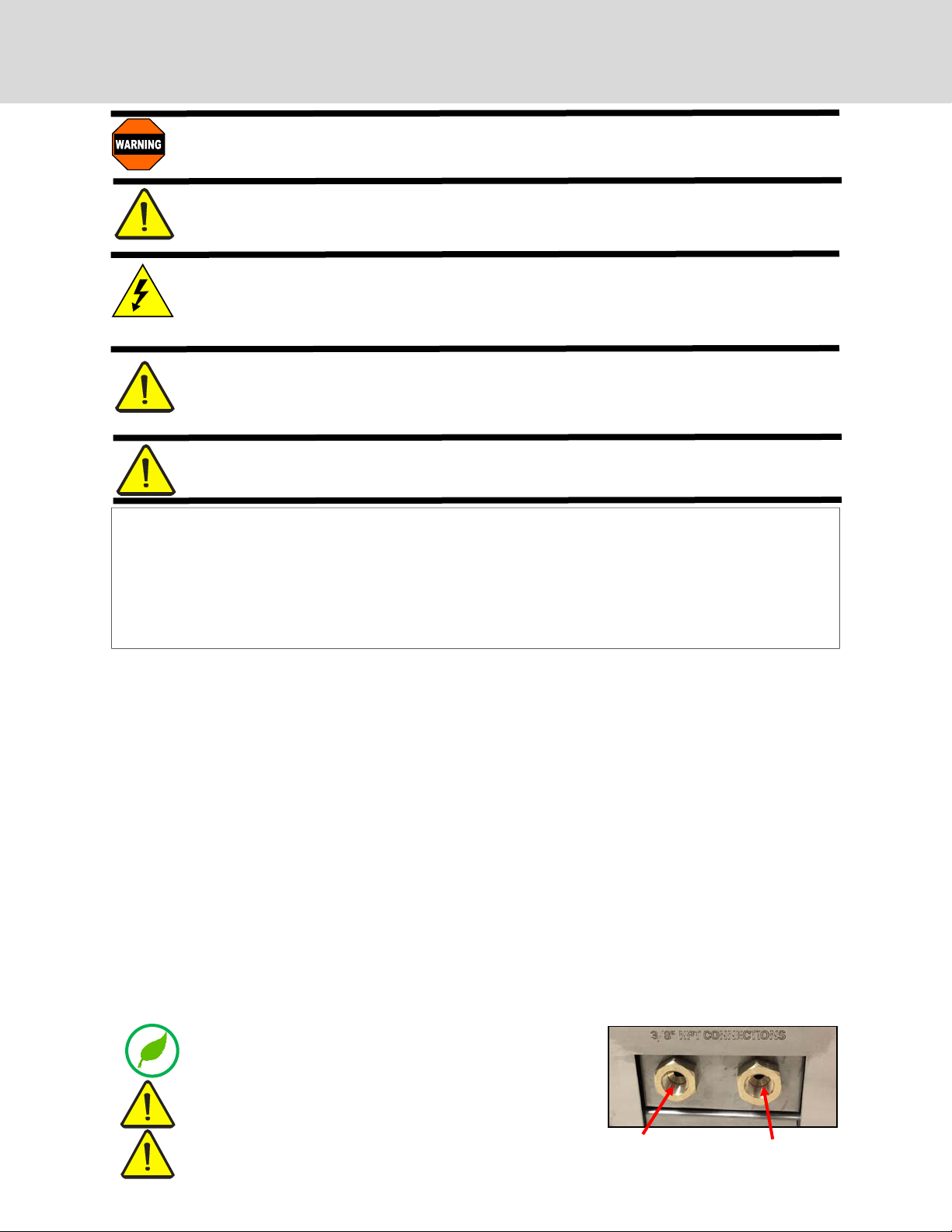
Connect city water supply and city drain to the 3/8” NPT female ttings at the back of the unit . Access to the
connections will be at the back of the cabinet. NOTE: This unit is to be installed with adequate backow protection
to comply with all applicable federal, state and local codes.
City water connection must not be further than 10 feet from the cabinet and no higher than 6 feet from the
connections. A minimum of 35 PSI is required to feed the cabinet.
Install the lights and diuser panels (instructions on page 20)
The 120V electrical outlet should be within 6 feet of the cabinet. Do not use an extension cord. Connect to a properly
grounded outlet according the electrical specications for the cabinet. See page 3 for specications.
Pipes that have not been in regular use should be cleaned an ushed
with running water prior to connecting to cabinet
Make sure the water inlet hose and drain hose are not twisted, crushed,
entangled or leaking. Do not use connection hoses that have been used
previously for other appliances.
If the unit is built in to a wall or structure, make sure that it can
be easily moved for access to the back and side panels for
service and maintenance.
6
City DRAIN connection:
3/8” NPT female fitting
City FILL connection:
3/8” NPT female fitting
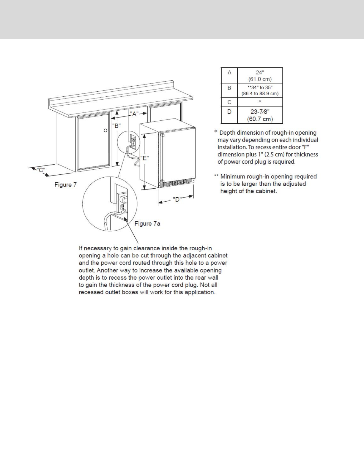
CUTOUT DIMENSIONS
7
START-UP
Note: the cabinet must be plugged in or wired and plumbed by a professional technician to all applicable local and state plumbing
and electrical codes. When you power up the unit in, it will turn on and you will see the startup screen (A). The unit runs diagnostics and start-up functions while this screen is visible. You do not need to do anything while the startup screen is showing. The
unit will automatically go to the HOME screen following the start up screen. To unlock the screen, press any button and a number
pad will appear. Enter “1551” then ““. Note: when the cabinet sits for long periods of time or it is turned o and then on again, it
will automatically revert to locked mode. You will have to use the unlock code any time this happens. Follow these steps to set up
your Herb cabinet for the rst time:
A
B
C
D
E
F
GCV12: 2 zones
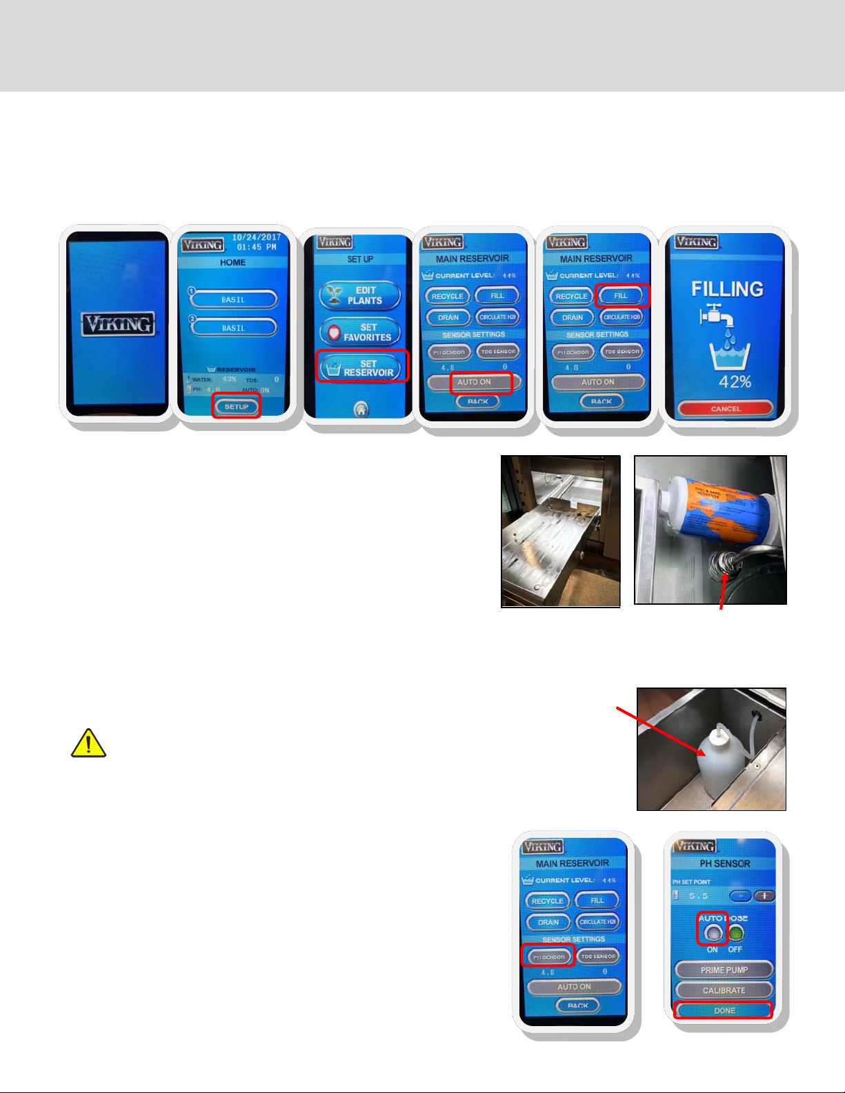
FILL THE WATER RESERVOIR USING CITY WATER
Ensure water lines are hooked up rst (see page 6). Ensure the reservoir is free
of dirt and foreign objects before lling.
1. Remove the lower grow drawer to access the water reservoir
2. From the home screen (B), press SETUP, SET RESERVOIR (C), AUTO ON (D)
to switch to city water mode*
3. Press FILL (E) and check to make sure the water is lling into the reservoir.
The screen will display FILLING (F).
4. Once full, the cabinet’s onboard computer will maintain a constant water
level
*For manual lling, make sure to press AUTO OFF, then ll manually to the top
of the oat sensor (about 3.25” deep). Water level must be monitored and replenished if it gets low.
SET UP THE pH DOSER (pH down solution required)
Note: Auto dosing requires that the irrigation pump be primed rst.
See page 10 for instructions.
1. Remove the lower grow drawer to access the dry box (Fig. 3)
2. Place a pH dosing bottle in the dry box. Any clean bottle will do as long as
it is not taller than the dry box. Drill a hole into the cap to insert the dosing
line. If the cap is the same size as your pH down solution bottle, place the
cap from the dosing bottle onto the pH down bottle. If they are not the
same size, ll the pH dosing bottle with pH down solution. Place the bottle
into the dry box.
3. From the home screen (B), press SETUP, SET RESERVOIR (C), then
4. Press PH SENSOR (F), then
5. Set AUTO DOSE to ON (G) and then
6. Press DONE (G)
The onboard computer will check every hour and will run the dosing pump as
needed to maintain the PH level. Default PH is 5.5, but can be changed on the
SET RESERVOIR screen. Most plants need a pH level of 5 to 7.
See growing tips on page 16 regarding low pH.
Note: Calibration does not need to be done on initial set-up.
8
Fig. 1
Access the water
reservoir
Fig. 3 Dry box with pH
dosing bottle
F
Fig. 2 Float switch/sensor;
right side of reservoir;
shuts off water once filled
to proper level
G
Continued on next page
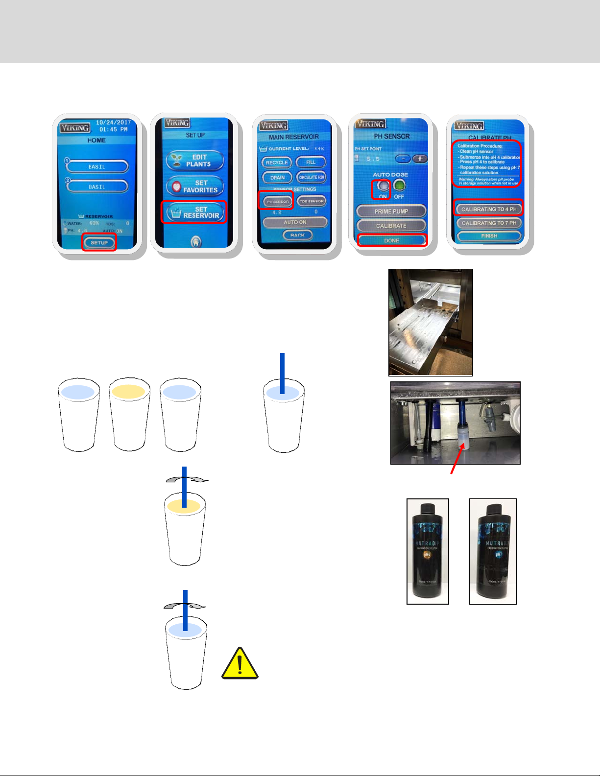
CALIBRATE THE pH SENSOR
START-UP (continued)
A
1. Remove the lower grow drawer to access the reservoir (Fig.1)
2. Locate the pH sensor probe on the right side of the reservoir (Fig.2)
3. Fill one cup of water, one cup of pH buer #4 (Fig. 3) and one cup of pH buer #7
(Fig. 4)
4. Remove cap from the sensor and gently wash the pH probe in the water and dry on
a clean cloth.
B
C
D
E
Fig. 1 Access the
water reservoir; the
sensor will be on
the left side.
water
5. Gently swish the
probe in the pH buer
#4. Continue to swish
the probe and follow
instructions in step 6.
7. Wash the pH sensor
in the cup of water
and dry on a clean
cloth. Repeat steps
5 and 6 for pH buer #7 solution
#4
#7
#4
#7
water
6. Enter the pH calibration screen press
SETUP (A), SET RESERVOIR (B), PH
SENSOR(C), then CALIBRATE (D) and
follow the instructions on the screen.
Calibration will take about three minutes
to complete.
8. Press DONE when calibration is complete
IMPORTANT: Safely store the pH sensor cap and use it to stop the
sensor from drying out when the water reservoir is empty. Do not
let the pH sensor dry out. Fill cap with pH #4 calibration solution
before placing it on probe to store the sensor. Failure to follow this
procedure will ruin the sensor and void the warranty.
Fig. 2 Blue PH sensor (shown with cap on)
Fig. 3
PH buffer #4
Fig. 4
PH buffer #7
Continued on next page
9
START-UP (continued)
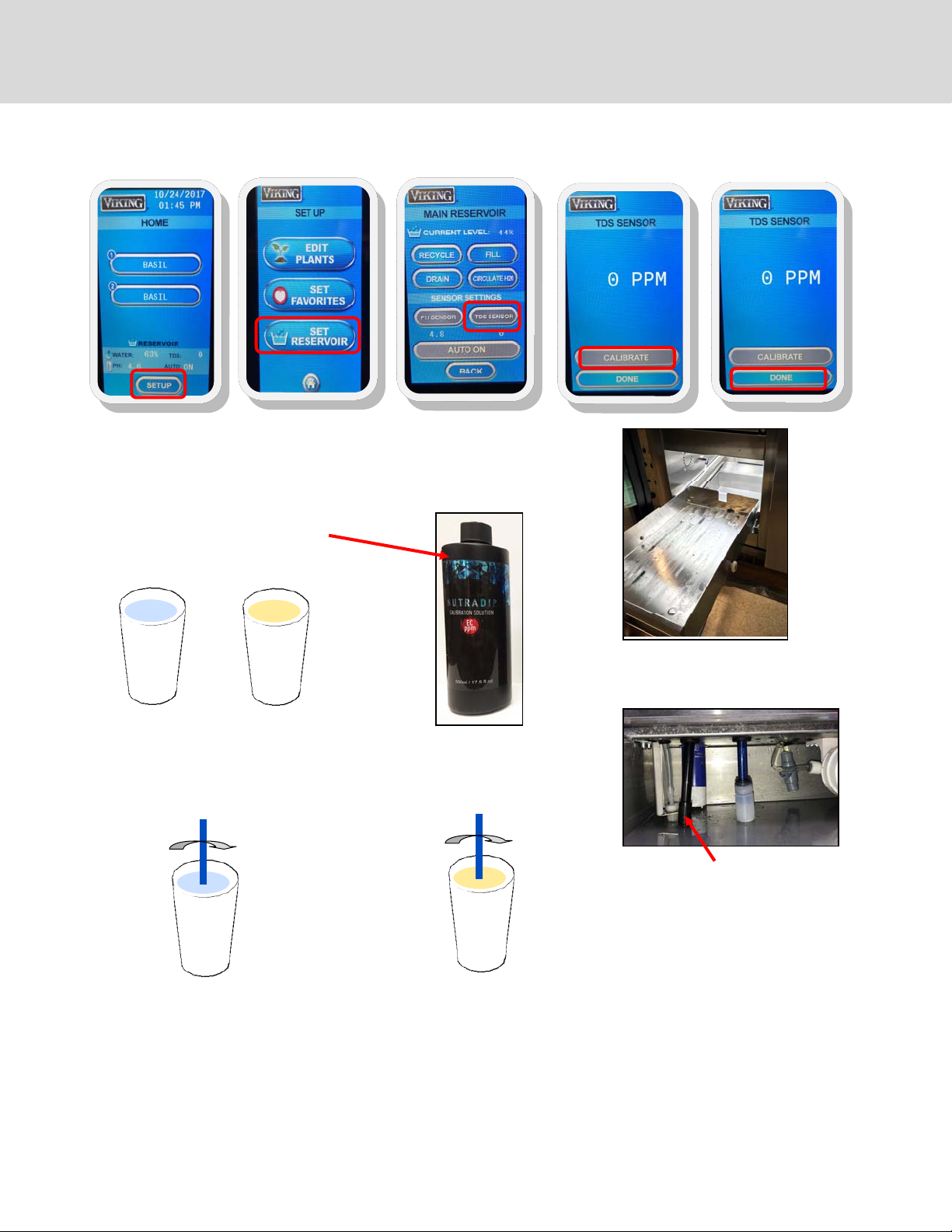
CALIBRATE THE TOTAL DISSOLVED SOLIDS (TDS) SENSOR (EC 1000 PPM solution required)
A
1. Remove the lower grow drawer to access the reservoir (Fig.1)
2. Locate the TDS sensor probe on the right side of the reservoir (Fig.2)
3. Fill one cup of water, and one EC
1000 PPM solution
B
C
D
E
water
4. Gently wash the TDS probe in the
water and dry on a cloth
water
EC
PPM
Fig. 1
Access the water reservoir
5. Gently swish the probe in EC PPM solution and, while swishing the probe,
enter the calibration screen.
Fig. 2
TDS sensor (black)
EC
PPM
6. To enter the TDS calibration screen press SETUP (A), SET RESERVOIR (B), TDS SENSOR(C), then CALIBRATE (D) and follow the
instructions on the screen. Continue to swish the probe in the solution for three minutes.
Calibration will take about three minutes to complete.
Press DONE (E) when complete.
Continued on next page
10

PRIMING THE IRRIGATION PUMP
START-UP (continued)
Access reservoir (Fig. 1)
1. If present, remove the bottom grow tray
2. Slide out drawer to access the reservoir
Fill reservoir
1. Make sure that the unit has been connected to the water and power
according to local codes
2. From the HOME screen, press SET UP, SET RESERVOIR, AUTO ON, FILL
3. Wait until the reservoir is full with water. Monitor the lling of the reservoir to assure proper ll.
Fig. 3
Priming valve in
OPEN position
Fig. 4
Priming valve in
CLOSED position
Fig. 1
Fig. 2
Irrigation pump
Priming valve
Priming
1. Access the priming valve near the irrigation pump. It should be in the OPEN position and
water should be owing downwards into the reservoir
2. From the HOME screen, choose ZONE 2 (A). This will be the growing zone that is directly
above the pump. Press WATER NOW (B).
3. Open (1/4 clockwise turn) and wait for steady stream of water to come out of the priming
valve (Fig 3); once you have a steady stream of water, close the valve (Fig 4).
4. Water should now be owing steadily from the irrigation nozzle in the zone selected in
step 2 (Fig. 5). Press WATER NOW (B) to turn o the watering cycle for that zone. Leave
the priming valve in the CLOSED position.
Your pump is now primed.
Fig. 5 Zone
irrigation nozzle
A
B
11

SETTING UP YOUR GROWING CYCLES
Note: The cabinet must be plugged in or hard wired and plumbed by a professional technician. Follow these steps to set
up your cabinet for the rst time.
GCV12
2 zones
A
SET UP THE DATE AND TIME
On the home screen, press the date/time in the upper right hand corner. This will take you to the TIME AND DATE SCREEN (A).
Using the UP and DOWN arrows, set the date and time.
Press DONE when you are nished.
The date and time are now set so you can accurately program and monitor the growing cycles.
SELECT SEEDS FROM THE SEED LIST
The cabinet comes with pre-set cycles for growing a variety of plants. It can also be programmed to set up the zones for special
seeds or changing the lighting and watering cycles for each plant. On the HOME screen (B), select the zone for the seed you
would like to program: GCV12 (2 zones). On the zone screen (C), press CHANGE SEED and you will be taken to the FAVORITES
screen(D).
An alphabetical list of preprogrammed seeds will appear. Scroll through the list to nd the seed you want, using the NEXT button to get to each screen (there are 5 screens, with a few spaces left empty at the end for custom programming of new items).
NONE is the rst item and can be used for designating shelves that might not be needed during a particular growing cycle. A
list of the preprogrammed seeds appears on page 14. Press SELECT to choose your seed. Repeat for each of the zones you wish
to use.
B
C D
Continued on next page
12

SETTING UP YOUR GROWING CYCLES (continued)
PROGRAMMING LIGHTING AND WATERING CYCLES
You can change the lighting and watering cycles for specic seeds, or new seeds that are not in the default programming
cycles.
EDIT CYCLES
From the HOME screen (A), press SET UP. On the SET UP SCREEN (B), press EDIT PLANTS.
From the SEED LIST SCREEN (C), Select a plant and then the cycle will appear for that zone. On the EDIT SCREEN (D), you will see
buttons for temperature, water and lights. You may also edit plant names on this screen for new seeds.
A
B
C
D
To change the temperature for when the fans turn on, press to increase or decrease the temperature. You
may also set the RH using the + and - buttons next to the RH symbol. Fans will come on if the temperature
and/or the RH rises above your settings.
To change the lighting cycle, press CHANGE to scroll through the lighting options. They are OFF, 12/DAY,
16/DAY, 18/DAY, 20/DAY (12, 16, 18 & 20 are the hours the lights will be on each day; default is 18 hours per
day)
To change the watering cycle, press and use the arrows to select a watering cycle. The choices for watering cycle are:
OFF: (no watering cycle)
1X DAY: (once each day)
2X DAY: (twice each day)
1-2 DAY: (once every other day)
1-3 DAY: (once every 3 days)
1-4 DAY: once every 4 days (default for most cycles; soil germination)
1-5 DAY: once every 5 days
Note: once or twice a day watering cycles are normally used for growing hydroponically, depending on your hydroponic growing
media, i.e. perlite, mats, etc.)
You may also change the duration of the watering cycle anywhere between 1 and 10 minutes. Press the + and - buttons to
increase or decrease the minutes. The default is 5 minutes. Press BACK when you are nished. You can select another plant to
change or press to return to the HOME screen.
To change a plant name, press PLANT NAME; a keyboard will appear and you can type in a new name.
Press “” to save the name. You can then edit the cycles for your new seed.
SET YOUR FAVORITE PLANTS
You can reduce the size of your plant selection list from the home screen to just your favorites so you
don’t have to scroll through the entire list of saved plants to nd your favorites; at the same time you will
keep the programming for all of your plants, when you need them.
From the HOME screen, press SETUP, then from the SETUP screen, select SET FAVORITES. You will see the
entire list of plants you have stored in the controller. To set your favorites, press the screen to the right of
the plant names you would like to make your favorites. A little heart will appear, indicating that the plant
is now a favorite. To de-select plants from the list, press the heart button until it disappears. You can scroll
through the entire list using the NEXT button. To save your favorites, press the HOME button
13
Continued on next page

SETTING UP YOUR GROWING CYCLES
TO START A GROWING CYCLE
On the HOME screen, select a seed for the zone you have just planted (Fig. 1), and you will enter the screen with the settings for that
zone (Fig. 2).
Press START CYCLE (may also say RESTART CYCLE if the same cycle has been started in the past) and a cycle will begin. Then press the
HOME button. Repeat for each zone that you have planted. Dierent zones can be started on dierent days, so not all have to be active at the same time and you can stagger growing cycles.
The water pump will operate at the top of every hour to circulate the water and mix nutrients. In the GCV12, it will run for one minute.
Fig. 1
Fig. 2
OTHER FUNCTIONS IN THE ZONE SCREEN
If you plant something dierent or move trays from one zone to another, you
can change to the cycle for a dierent seed by pressing CHANGE SEED. This will
take you to your FAVORITES menu and you can select from your favorites.
If you would like to do an unscheduled watering, you can press the WATER
NOW button and start a watering cycle. Monitor the watering cycle and press
the WATER NOW button again when you would like the watering cycle to stop.
To cancel a growing cycle, go to the ZONE screen for the particular cycle you
want the cancel. Press RESTART CYCLE. This will cancel the existing cycle and
automatically start a new cycle. You will see the day counter on the top right of
the screen revert to DAY 00.
OTHER FUNCTIONS IN THE MAIN RESERVOIR SCREEN
From this screen, you can automatically drain and ll your cabinet using the DRAIN and FILL buttons. In addition to the regular DRAIN
and FILL functions, there is also a RECYCLE function. This function can be used when all you want to do is exchange old water for new
water in the cabinet.
CAUTION:
The cabinet MUST be hooked up to city water connection AND drain for doing any of these functions. It is equipped with a
“last chance” safety option to not do an automatic drain. This is built in to make sure you are hooked up to municipal water and drain before you perform any drain or recycle operation. The screen will ask if you are sure before beginning the
draining process. A draining screen will appear for you to monitor the progress on the draining cycle.
The cabinet will automatically circulate the water in the reservoir every hour. However, the CIRCULATE H2O button can be used
when adding nutrients. It will activate the water pump to stir and distribute the water in the reservoir after adding nutrients. It will
run for one minute in the GCV12.
14

LETS’ GROW!
PLANTING & GROWING
Planting and growing is easy. Follow these simple instructions. See the growing guide for specic plants on the next page.
Please refer to the Growing Guide and Growing Tips on pages 16-17 for successful growing and harvesting of specic plants.
See Sanitation and Safety Guidelines and FAQ’s on pages 20-21 for safe growing and harvesting.
Materials Needed (planting using soil)*:
Potting Soil (sterile) Screen/Mat 1—20 gal plastic tub (unsifted soil); smaller tub (sifted soil)
Seeds Shaker Humidity domes
10” x 20” planting trays** Sifter Measuring cups & spoons (for measuring seed quantities)
Misting bottle
*If you are planting hydroponically, you will need a soil-free medium such as perlite or soil free mat instead of soil
**You may also use 10” x 10” planting trays; 2 will t in the same space as a 10” x 20”
1. PLACE SOIL INTO ONE OF THE TUBS
2. USING SIFTER, SIFT SOIL INTO THE SECOND TUB; YOU WILL NEED ABOUT ONE TO 1.5 CUPS OF SIFTED SOIL PER TRAY TO BE
PLANTED
3. ADD MORE SOIL TO THE FIRST TUB, ENOUGH TO FILL PLANTING TRAYS 1/2 TO 3/4 FULL AND MOISTEN SOIL ENOUGH TO MAKE IT
DAMP AND CRUMBLY—NOT WET AND MUDDY; STIR WHEN ADDING WATER; DO NOT ADD WATER TO THE TUB OF SIFTED SOIL
4. INSERT MATS INTO PLANTING
TRAY(S)
7. SECURE HUMIDITY DOME. MAKE
SURE DOME VENTS ARE CLOSED
5. PUT MOIST UNSIFTED SOIL IN
TRAY(S), FILL TO 1/2 TO 3/4
FULL, AND SMOOTH
8. PLACE TRAY(S) ON SHELF IN
CABINET
6. MEASURE OUT SEED QUANTITY AND SEED EVENLY
WITH SHAKER (see
amounts in Growing Guide,
p. 15). SPRINKLE JUST
ENOUGH SIFTED SOIL OVER
SEEDS TO COVER THEM. IF
THE TOP LAYER OF SIFTED
SOIL IS DRY, MIST LIGHTLY
TO MOISTEN (do not soak
the top layer).
9. SET PROGRAM FOR LIGHT
AND WATERING SCHEDULE
ACCORDING TO THE
GROWING GUIDE
10. LEAVE DOME(S) ON FOR AT LEAST 48 HOURS
(until seeds sprout)
11. REMOVE THE HUMIDITY DOME(S) FOR THE
REMAINDER OF THE GROWING CYCLE
12. HARVEST!
Harvest all greens
15
Or thin out greens and use as they grow

GROWING GUIDE
Seed Sowing Amount
seeds per 10”x20”
tray
Amaranth 2 tsp 2-3 days 2 weeks 1 every 4 days 3 oz (95g)
Arugula 1 tsp 2-3 days 3 weeks 1 every 4 days 4.7 oz (145g)
Basil 1 tsp 2-3 days 4-5 weeks 1 every 5 days 7.5 oz (235g)
Beet Tops 1/2 cup 2-3 days 2 weeks 1 every 4 days 4.3 oz (135g)
Broccoli 1 tbsp. 2-3 days 1 week 1 every 4 days 8.4 oz (260g)
Buckwheat 1/2 cup 2-3 days 1 week 1 every 3 days 13.3 oz (415g)
Cabbage 1 tbsp 2-3 days 2 weeks 1 every 4 days 5.2 oz (160g)
Chervil 2 tbsp. 8-10 days 3 weeks 1 every 4 days 4.5 oz (140g)
Chives 2 tbsp. 4-7 days 2 weeks 1 every 4 days 2.6 oz (80g)
Cilantro 1/4 cup 8-10 days 3 weeks 1 every 4 days 4.3 oz (135g)
Dill 1 tbsp. 4-7 days 3 weeks 1 every 4 days 3.5 oz (110g)
Fenugreek 1/4 cup 2-3 days 2 weeks 1 every 4 days 6.4 oz (200g)
Flax 1 tbsp 2-3 days 2 weeks 1 every 4 days 2.7 oz (85g)
Kale 1 tbsp 2-3 days 2 weeks 1 every 4 days 6.4 oz (200g)
Komatsuna 2 tsp 2-3 days 2 weeks 1 every 4 days 6.4 oz (200g)
Lemon Balm 2 tsp 8-10 days 4 weeks 1 every 4 days 3 oz (95g)
Lentils 1/2 cup 2-3 days 1 week 1 every 4 days 5.7 oz (180g)
Lettuce 1 tbsp 4-7 days 3 weeks 1 every 4 days 2.1 oz (65g)
Marjoram 1 tsp 4-7 days 4 weeks 1 every 4 days 1.3 oz (40g)
Mizuna 1 tbsp 2-3 days 2 weeks 1 every 4 days 4 oz (124g)
Mustard 1 tbsp 2-3 days 2 weeks 1 every 4 days 6.4 oz (200g)
Nasturtium 1/2 cup 4-7 days 1-2 weeks 1 every 4 days 9.3 oz (290g)
Oregano 1 tsp 4-7 days 4 weeks 1 every 5 days 1 oz (32g)
Parsley 1 tbsp 4-7 days 3 weeks 1 every 4 days 5.4 oz ( 168g)
Pea, Sugar 1 cup 2-3 days 2 weeks 1 every 4 days 9.6 oz (300g)
Pea 1 cup 2-3 days 2 weeks 1 every 4 days 9.6 oz (300g)
Peppercress 1 tbsp 2 days 2 weeks 1 every 4 days 4.5 oz (140g)
Radish 2-3 tbsp. 2-3 days 1 week 1 every 4 days 10.3 oz (320g)
Sage 2 tbsp 2-3 days 2 weeks 1 every 4 days 2.7 oz (85g)
Savory 1 tbsp 2-3 days 2 weeks 1 every 5 days 1.1 oz (35g)
Shiso 2 tsp 2-3 days 2-3 weeks 1 every 4 days 4.1 oz (128g)
Sorrell 2 tsp 2-3 days 2 weeks 1 every 4 days 3 oz (92g)
Sorrell, Ruby Veined 1 tsp 4-7 days 2-3 weeks 1 every 4 days 5.3 oz (165g)
Sunflower 1 cup 2-3 days 1 week 1 every 4 days 12.2 oz (380g)
Swiss Chard 1/2 cup 4-7 days 3 weeks 1 every 4 days 4.3 oz (134g)
Thyme 2 tsp 4-7 days 4 weeks 1 every 5 days 1.6 oz (50g)
Wheatgrass 1 cup 2-3 days 1 week 1 every 4 days 8.3 oz (258g)
*Yields may vary depending on seed variety, quality and growing conditions
¹For soil-free (hydroponic) growing, change watering cycle to once or twice per day; frequency is dependent on t ype of media that is used
Dome On Time
(germination)
Grow Time
(harvest)
Watering
Schedule¹ (soil)
Harvest Yield
per Tray*
NOTE: If sowing
multiple varieties
of seeds in the
same growing
zone, set watering
to once per 4 days
16

GROWING DO’S AND DON’T’S
DO MAINTAIN TEMPERATURE AND HUMIDITY
Keep the room temperature between 55°F and 90°F (13°C and 32°C), and the humidity level in the cabinet between
30 and 60%.
DO KEEP IT CLEAN
Keep your growing environment clean. Clean the reservoir, reservoir lter and growing shelves every month accord-
ing to the cleaning instructions on pages 17-19.
DON’T OVERWATER
Overwatering, especially at the beginning of the growing cycle can bring on mold and mildew. Most watering cycles
have been pre-set for every 4 days and are usually sucient for most plants, depending on the ambient temperature
and humidity.
DO USE HUMIDITY DOMES DURING GERMINATION
The humidity domes increase the temperature and humidity to enhance germination. Keep them on the trays for the
rst 2-3 days, with the vents closed. Remove them when the seeds start to sprout.
DO USE PROPER SOIL OR MEDIA
Purchase clean potting soil from a reputable supplier. Make sure there is a lter pad in the bottom of the tray to keep
soil from running into the water reservoir. We have had good results with Happy Frog brand potting soil, but there
are many choices on the market. Don’t use garden soil as it can get compacted and interfere with proper watering. If
growing hydroponically, purchase mats or other hydroponic media such as perlite. Note: depending on the media,
growing results may be dierent than soil. You may have to experiment with hydroponic media to determine which
type works best for growing dierent plants. There are many resources online describing the use, pros and cons of
the dierent types of media that are available. For discussion on hydroponic growing media, consult
www.epicgardening.com
DON’T OVERFEED
Overfeeding can cause damage to plants. For best results follow the instructions on your nutrient bottle. Most quick
growing micro greens (one to two weeks) do not require any nutrients. Greens with a longer growing cycle (herbs,
arugula, etc.) or greens that are used for multiple harvests require nutrients, and should only be added after week one
or two at the earliest.
DO KEEP pH LEVELS BETWEEN 5 AND 7
Balance your pH level at 5 in the beginning of the growing cycle for best results, as the pH is likely to increase as the
cycle goes on. The cabinet is equipped with an automatic dosing system to keep pH levels from going too high. Be
sure to check your dosing bottle regularly to make sure it doesn’t run out. Low pH is rare, but if it occurs citric acid
(organic) or potassium hydrochloride can be used to raise the level. Make sure they are mixed according to manufacturer’s direction and used sparingly. These and other hydroponic supplies can be purchased at a local hydroponic
growing store or on the internet.
DO SOW SEEDS A LITTLE ON THE HEAVY SIDE
Thin out young plants and allow others to grow and ll out.
DO USE HYDROGEN PEROXIDE
If you accidentally keep your humidity domes on too long or overwater your seeds, they may develop powdery mil-
dew. You can spray them with a mixture of hydrogen peroxide and water. Mix 1 tbsp. of hydrogen peroxide (17-35%
food grade) in 1 quart of water. Spray only the soil, as the solution can cause plants to rot in on themselves.
DO LOVE YOUR PLANTS!
Take time and care with your plants. Check them frequently for mold or other kinds of stress. You can see great
growth, even in one day!
17

CLEANING AND MANTENANCE
CLEANING THE RESERVOIR & IRRIGATION SYSTEM
1. Make sure cabinet is connected to city drain and water. If you are not hooked up to a drain and city water you will need to manual-
ly drain and ll the cabinet; if this is the case, connect the drain tting to a hose that runs to a drain or sink. Do not activate the DRAIN
function until you have a place to drain the water with a hose to a sink or drain, observing all municipal codes. Used water from the
cabinet is not potable.
2. Remove the bottom drawer(s)
3. From the HOME screen, press SETUP
4. In the SETUP screen, press SET RESERVOIR
5. Press DRAIN. The next screen that appears will ask if you are sure. Double check that the cabinet is hooked up to a drain. Otherwise it
will drain onto your oor! If you are not sure, press no and double check. If you are sure, press YES.
6. The cabinet will start to drain the reservoir. This may take up to 20 minutes. Once the reservoir has been drained, wipe o any dirt
with a clean rag.
7. Add your preferred cleaning solution (i.e. hydrogen peroxide mixture) into the reservoir. Follow the guidelines on the label of the
agent. The capacity of the GCV12 is 3.25 gallons. H
8. From the HOME screen, press SET RESERVOIR, then FILL. Filling should take approximately 20 minutes.
9. When the reservoir has relled, from the HOME screen press ZONE 1 and then WATER NOW so that the cleaning solution ows through
the cabinet’s piping system to ZONE 1
10. Repeat step 9 for ZONE 2
11. Once the zones and reservoir are cleaned, from the HOME screen, press SETUP, SET RESERVOIR, then RECYCLE. This will drain the reservoir of the cleaning solution and then rell it with fresh water for your next growing cycle.
concentration should be 5 tsp per one gallon of water.
2O2
Step 3
Step 9
Step 4
Step 9
Step 5
Step 11
Step 5
Step 11
Step 6
Step 11
Step 8
Step 11
18

CLEANING AND MANTENANCE (continued)
CLEANING THE GROWING DRAWERS Clean your grow drawers between each harvest. However, keep a close eye on the
environment and immediately clean any mold or organic matter.
Do not use any chemically damaging or toxic cleaning products such as bleach. Do not use stainless steel cleaner on the
interior of the cabinet. Using chemical cleaning products can be toxic and also damage the stainless steel drawers and
cabinet. You can use 30% hydrogen peroxide to clean the reservoir and water lines (5 teaspoons per gallon of water).
Read all warning labels on the hydrogen peroxide or other cleaning products.
Keep your growing environment clean.
Clean the reservoir, reservoir lter and grow drawers every month.
GENERAL STAINLESS STEEL
CLEANING
Clean the exterior of your cabinet when ngerprints
and large amounts of dust appear on the outer surfaces. Using stainless steel cleaner from your local
hardware store, spray on and wipe down with a cloth
going with the grain (As seen in the pictures). DO
NOT USE STAINLESS STEEL CLEANER IN THE
RESERVOIR OR IN THE DRAWERS. Stainless steel
cleaner is to only be used on the outer surfaces of
your cabinet!
CLEANING CAUTIONS
When you wipe down the reservoir, do not knock the pumps, misalign the pipes or the sensors.
Draining the reservoir sends water down and out from the drain hose. Water from the cabinet is not for drinking as biological residues may still be present and could be harmful.
Do not use steel wool pads to clean the reservoir as they will damage the steel and its rust-resistant nish.
Do not use detergents or solutions that contain chlorides, ammonias, alkalis or abrasive cleaners. Use only environmentally safe, nontoxic solutions in the manufacturers’ recommended concentration. Non-chlorine bleach from an environmentally-friendly company
may be used in accordance with the guidelines on the packaging.
DAMAGE TO STAINESS STEEL IS PERMANENT, COSTLY TO REPAIR, AND IS NOT COVERED BY THE WARRANTY
19

PERIODIC MAINTENANCE PROCEDURES
INSIDE THE RESERVOIR
A. DRAIN, CLEAN AND FLUSH RESERVOIR (Monthly)
SEE INSTRUCTIONS ON PAGE 17
B. CHANGE FILTER (30-45 days*—more often in areas with
hard water; lter is washable for extended use)
1. Locate the lter (large blue or white canister in the reser-
voir) and unscrew the canister counter clockwise. Make
sure to support very well the lter mounting bracket
while unscrewing lter in order to reduce the risk of
breaking mount.
2. Remove and discard excess water.
3. Change the lter and screw the canister back into place
by lining tabs up with head and cartridge. Push until it
bottoms out, then twist clockwise.
You may need to re-prime the pump after this process. See instructions on how to prime the pump on page 10.
* How often you change your lter is dependent on whether you
are growing in soil or hydroponic media. Once you get through a
few growing cycles, you will be able to determine how often it
should be changed. One indicator the lter needs to be changed
is inadequate water ow to the trays during a watering cycle.
Water Filter
Water circulation pump; white
filter cap at bottom
C. CHECK AND CLEAN FILTER CAP (Monthly)
1. Remove the small white cap at the bottom of the blue
cylindrical circulation pump.
2. Rinse the cap.
3. Place the cap back onto the pump
* If the water ow to your growing drawers is inadequate during a
watering cycle, check the lter cap to see if it needs to be cleaned.
INSIDE THE GROWING ZONES
A. CLEAN DRAWERS (Monthly)
1. Remove a drawer from the cabinet
2. Use a clean cloth with hot soapy water or hydrogen peroxide
solution to wipe down the grow drawer; make sure the drain
holes are cleared of any debris.
3. Rinse o the drawer with clean water
4. Dry with clean cloth
5. Replace in cabinet
6. Repeat steps for all drawers
20

REPLACING THE LIGHTS
Occasionally you may need to replace a light bulb. It is a simple process, similar to changing the bulb on an aquarium hood.
For part number, see the list on page 26.
NOTE: T5 growing lights running at the default
time of 18 hours per day is considered high use
and the eciency of the bulbs will reduce approximately 10% after 20,000 hours. Bulbs should be
replaced every 18-24 months to ensure best performance.
Remove the diuser shield by pushing it up with both
hands, then pushing it back far enough for the front to
drop down, and then pull out.
Grab each end of the bulb (metal ends of tube), rotate
clockwise until you can pull the bulb out.
Insert the ends of the new bulb into the black ends of the
ballast, then turn counter-clockwise until the bulb snaps
into place.
Replace the shield by lifting it up and back over the notch
in the back of the cabinet, push up the front until it clears
the front of the diuser frame, pull forward and drop into
place.
Push up and back over
notch in back of cabinet,
then let front drop down
21

SANITATION AND FOOD SAFETY GUIDELINES
For your health and safety, please read the information
below regarding sanitation, safe growing and food
safety.
Micro greens and herbs are not sprouts, but rather, baby
plants with intense avor and nutrients. There are dierences in growing and harvesting micro greens that make
them much safer than sprouts.
Starting with Seeds
Make sure that all seeds you buy have been handled as a
food crop, not a farm crop. Seeds that have been in contact with animals or animal waste could be contaminated
with salmonella or E.coli O157 H7 and could lead to food
poisoning. Reputable seed suppliers test all lots of seed
for contamination.
Make sure that each container of seed is labeled with the
name of the seed producer or distributor, the lot number
and the country of origin.
Keep records to ensure trace-back and recall procedures.
Sanitation
Always use clean seed, as stated above, and soil, tested for
E. coli and salmonella.
Sanitize equipment; regularly clean an sanitize all growing
drawers, cabinet and reservoir with hydrogen peroxide
rate recommended below. We recommend a thorough
cleaning/disinfecting weekly, or when new trays are planted.
Don’t let greens or seeds come into contact with manure
or other contaminated organic material.
Hands and equipment must be kept clean at all times for
handling micro greens. We recommend food handling
gloves during planting and harvesting.
Water in the reservoir should be clean, potable water, tested for bacterial contamination.
It is recommended that 2% chlorine from calcium hypochlorite be used as a seed sanitation method if your intention is sprouting. This is not necessary for micro greens,
but can be done as an extra precaution.
Using Calcium Hypochlorite
Rate: 3 ounces calcium hypochlorite in 1 gallon of warm
water. Mix thoroughly and soak seed for 20 minutes. Rinse
seed thoroughly in clean water, then nish soaking time, if
required, in clean water. Avoid breathing the fumes of
chlorine. Masks should be worn to lter the fumes is you
choose this method.
Using Hydrogen Peroxide:
Soak seeds in hydrogen peroxide. Add 5 ounces of 5% hydrogen peroxide and one ounce distilled vinegar to one
quart of room temperature water. Pour the solution over
the seed and let stand for 5 minutes, making sure that all
of the seed is in contact with the solution. Drain and rinse
the seeds in clean water several times to make ensure the
solution has been removed. Plant seed as usual. This
again is recommended for sprouting, but not necessary for
growing micro greens and herbs.
Growing Conditions
The environment in which E. coli and salmonella thrive is
warm and moist. Most commercial sprouts are grown in
large tanks of water, which tumble the seeds much like a
washing machine tumbles clothes. In these conditions, if
one seed is contaminated, it will be spread to all of the
sprouts in the water bath.
Micro greens are not grown in water. We recommend
growing them in sterile soil or other sterile media. While a
sprout bath spreads pathogens from one sprout to another, soil acts like a lter, actually removing the source of
contamination.
Harvesting
While a sprout is consumed whole, including the leaves,
roots and seed husk, micro greens are newly germinated,
small plants like you’d nd in any garden. All micro greens
should be harvested with clean hands, or using food handling gloves, clipped at least 2” away from the root system
and soil, using clean disinfected scissors. Ensure all debris
is removed from micro greens and cleaned thoroughly
before consumption.
Refrigerate cut micro greens, except basil (cut basil is delicate and does not like the cold). Treat them and any foods
containing them as you would any nutritious food.
If you love sprouts, consider growing micro greens. Their
bright and intense avor will be even more enjoyable now
that you have condence that they are also safe to enjoy.
22

FREQUENTLY ASKED QUESTIONS & TROUBLESHOOTING
How much soil should I put in my trays?
You should ll each tray 1/2 to 3/4 full with sterile potting soil. Make sure the soil is well moistened, but not overly
muddy or soupy. See Resources page 25 for some brands we have found to be high quality soils. For seeds with a
shorter life cycle like pea shoots, radishes, wheatgrass (1-2 weeks), 1/2 full is adequate. For seeds with longer life cycles
such as basil, oregano, arugula, etc., go with 3/4 full.
Can I mix in my seeds or cover with dirt?
For the best results for germination, sprinkle them with a ne layer of sifted soil, just enough to cover the seeds. Usually 1 to 1-1/2 cups of sifted soil works. The ner soil spreads easily and provides a nice blanket over the seeds for germination so that more seeds sprout and at the same rate.
When should I use plant nutrients?
The cabinet will display total dissolved solids (TDS) of the water in the reservoir. Note what the TDS is when you rst ll
the reservoir and try to maintain a TDS of 100-250 above that number. Add 2.75 oz. (80ml) of nutrients at a time, wait
15 minutes to adjust the TDS.
Is the cabinet pre-programmed?
Yes, the cabinet is pre-programmed for the seeds listed on page 15 for soil growing. There are a few empty positions
open in the menu for adding more seeds and you can erase and replace items in the seed menu. You can also designate your favorite seeds for frequently used cycles. All of the seed programs are adjustable for light and watering
schedules.
How often should I perform maintenance on my cabinet?
The cabinet requires frequent monitoring and care. It should be inspected thoroughly and cleaned at least once a
month. This may vary with your usage, depending on the number and types of plants, nutrients and TDS build-up and
growing medium (soil vs. hydroponic). Please refer to maintenance and cleaning procedures in this manual.
Does the water reservoir keep itself lled?
Yes. If your cabinet has been plumbed and hooked up to municipal water supply, then it is pre-programmed exchange
the water in the reservoir once a week and top o as needed.
What do I do if the reservoir won’t recycle?
Check to ensure that the connection on your city drain is open and free of blockage. If the cabinet is new, it may not be
primed. See instructions in this manual on page 10 for priming the pump.
What do I do if there is a zone that won’t water?
Make sure only one zone is being watered at a time. Only one zone can be watered at one time, so watering schedules
for each zone will be staggered an hour apart, if they are programmed to water at the same time. Check the programmed schedule to ensure it is not programmed to be OFF. If still no watering, access the reservoir and insure that
the pump is on and primed.
What if I see a weak/no water supply to the drawers during a watering cycle?
It’s likely that the screen over the lter is clogged with debris and needs to be cleaned or the lter needs to be replaced.
See maintenance and cleaning instructions on page 19.
What if the drawers don’t appear to be draining properly?
Check the drain holes at the back of the drawers and clear them if they are blocked. A pipe cleaner is ideal for this
maintenance.
23

MICRO GREEN PROBLEMS
WHITE MOLD
SLOW GERMINATION
Identication Remedy
White mold looks like a spider web crawling
across the surface of the growing media. It starts
out in one area in a small, wispy ball and then
expands quickly over the growing media.
Make sure your trays are CLEAN before
you plant
Decrease the humidity by increasing air
circulation
Decrease the seed density of your future
plantings, especially for mucilaginous
seeds
Try using some grapefruit seed extract
mixed with water as an organic solution
Identication Remedy
Most micro green seeds germinate in 2-4 days,
but some may take a bit longer. If you’re seeing
germination times that are longer than what is
outlined in the table on page 15, something is
wrong.
Increase moisture in the tray by misting
or running an unscheduled watering
cycle
Do a germination test on a paper towel
to see if the seed is bad. Place a paper
towel in a growing tray, moisten it by
misting with a mister and sprinkle the
seeds on top. Cover with a propagation
dome and see if they sprout.
CLUMPY MICROGREENS
FAILURE TO THRIVE
Identication Remedy
When you’re spreading your seed out in trays, it
can be dicult to get an even spread. If you
plant too densely, they will clump together, especially if their mucilaginous. When they sprout, a
few of the seedlings will push the rest of them up
into the air, suspending the roots and possibly
bringing dirt along with them. It makes harvesting dicult.
Decrease total seed volume planted in
each tray
Spread seeds more evenly throughout
the tray
Identication Remedy
The greens look weak and pale. This is an all
encompassing condition that could result from a
number of factors. It is dicult to troubleshoot
this condition if all of the other conditions above
have been addressed.
The weakness could be due to a lack of moisture
control—either too dry or too wet. In some cases
the seed is not properly planted, or the humidity
dome is removed at the wrong time.
Make sure to read the seed growing
instructions on the packets of seeds
Stick to a normal watering schedule
Make sure you leave the humidity domes
on for an adequate amount of time
If growing hydroponically, check your
nutrient concentration; make sure nutrients are mixed according to the manufacturers directions
24

RESOURCES
The growing cabinet comes with a starter set of domes and trays. An optional starter kit is available and includes growing
trays, domes, mats, sifter, TDS calibration solution, PH kit, hydrogen peroxide, 20 gallon plastic tub (for mixing/sifting soil)
and measuring syringe (for adding nutrients).
Many supplies, including seeds and growing media, can be found at local greenhouses and garden supply sellers. The internet is a great resource for nding everything you need for your growing cabinet. A list of some resources is on the next page.
TDS reader: for measuring
the initial TDS of your water
Growing trays (with
drain holes) and
vented domes
supply
Plastic tubs for mixing and
sifting soil
Sterile soil or hydroponic growing media
Seeds: purchase from
reputable supplier
Sifter to sift dry soil to cover
seeds for germination
Growing mats/filters to keep
soil from running out of the
trays into the water. Thicker
mats can be used for hydroponic growing
Rockwool or stonewool starter cubes/trays for hydroponic growing.
Perlite, coconut coir and other media
may also be used. For discussion on
hydroponic growing media, consult
www.epicgardening.com
Measuring syringe to add
nutrients
Plant food: for hydroponic
growing or seeds with
longer growing cycles.
Seeds with shorter growing
cycles get enough nutrients
from the soil
PH kit: PH#4 and PH#7 bottles to
calibrate the pH probe.
TDS 1000 EC ppm solution: To
calibrate total dissolved solids
probe
25

List of brands for supplies*
RESOURCES
Growing trays
(with drain holes)
and vented
domes:
Mondi™
Super Sprouter™
Sun Systems™
Sterile soil:
Fox Farms Happy Frog™
Miracle Gro™
Hydroponic growing media
(perlite, rockwool):
Handy Pantry™
Miracle Gro™
Therm-O-Rock™
Viagrow™
Plant It™
Grodan™
Growing mats/lters:
Handy Pantry™
For discussion on hydroponic
growing media, consult
www.epicgardening.com
TDS reader:
Milwaukee™
Plastic tub for mixing and sifting soil:
Rubbermaid™
pH and TDS Calibration Solutions:
Nutradip™
General Hydroponics™
Seeds:
Johnny’s Selected Seeds™
Burpee™
Cahaba Clubs Herbal Outpost™
Eden Brothers™
pH down and pH up solutions*:
Nutradip™
General Hydroponics™
Botanicare™
Plant food:
Miracle Gro™
Jungle Juice™
General Hydroponics Flora Series™
Fox Farm Gringo Rasta,™ Bush Doctor™
and Hydroponic Trio™
* Do not use solutions intended for swimming pools.
These are not safe for plants.
* This is not a compete list or an endorsement of these products. Brands are trademarked and not affiliated with Viking Range, LLC
26

REPLACEMENT PARTS - GCV12RSS & GCV12LSS
MICRO GREEN & HERB CABINET COMPONENTS 120V, 1.6 A
Part Number Description
18050-0051 leveling bolt
18310-0209 22” drawer slide
29038-5154 18” tempered glass door (GCV12)
29038-3263 polymatte light diffuser panel
18616-0415 T5 growing light fixture and bulb
18614-0322 muffin fan 115V
18616-0224 transformer 120/208/240, 24V40VA
18615-0172 3/8” female NPT tube fitting
18607-0017 terminal board CH03265
18602-0002 water level float switch
18605-00130 16/3 HSJO Cord without plug
18615-0176 Straight 1/2” NPT to 3/8” tube fitting
18615-0179 Straight 1/4” NPT to 3/8” tube fitting
18615--0222 90 degree elbow 1/4” NPT to 3/8” tubing
18616-0419 TDS sensor
18616-0420 pH sensor
18616-0423 temperature/RH sensor w/housing
18614-0115 water pump 12VDC
18614-0397 peristaltic pump 12VDC
18614-0124 water filter replacement cartridge
18614-0033 solenoid valve 3/8” tube 5/16” ORF
18615-0166 3/8” bulkhead tube fitting
Part Number Description
18616-0451 power supply, 12 VDC, 120 VAC
18616-0438 Isolation board
18616-0425 cable, HUBA press transmitter
18616-0418 press transmitter type 400
18615-0168 ball valve 3/8” tube
18615-0161 tee 3/8” tube
18617-0049 rubber plug grommet 9600K44
18614-0035 Solenoid valve HD 120
18614-0316 muffin fan cord, 40” #4C552
18614-0164 straight fitting 3/8” tube x 3/8” NPT
18616-0416 I/O board
18616-0417 touch screen 4.3
18615-0169 rubber hose 1/4 ID x 3/8 OD
18615-0162 90 FTG 3/8” tube
18616-0422 CAT cable
18615-0167 3/8” polyurethane tubing
18616-0434 EVA tubing, .188 ID x .312 OD
18616-0435 .312 OD tension spring clamp
18616-0436 nylon loop clamp 1-1/2” ID
18616-0430 propagation tray with drain holes, 10” x 20”
18616-0429 propagation 4” dome 10”x 20” w/ vents
27

WIRING DIAGRAM
CAUTION: Use only (OEM) original equipment manufacturer replacement parts. Using unauthorized
parts may cause serious injury or damage to the cabinet. Replacement parts should be installed by a
qualied service technician.
Contact Viking Range Preferred Service at 888-845-4641 with your model and serial number for replacement
parts.
28

PLUMBING DIAGRAM
CAUTION: Use only (OEM) original equipment manufacturer replacement parts. Using unauthorized
parts may cause serious injury or damage to the cabinet. Replacement parts should be installed by a
qualied service technician.
Contact Viking Range Preferred Service at 888-845-4641 with your model and serial number for replacement
parts.
29

SERVICE INFORMATION
If service is required, call your authorized service agency.
Have the following information readily available:
• Model number
• Serial number
• Date purchased
• Name of dealer from whom purchased
Clearly describe the problem that you are having. If you are unable to obtain the name of an authorized service agency, or if
you continue to have service problems, contact Viking Range at (888) 845-4641 or write to:
VIKING RANGE, LLC
PREFERRED SERVICE
111 Front Street
Greenwood, Mississippi 38930 USA
Record the information indicated below. You will need it if service is ever required. The serial number and model number
for your appliance are located on the serial tag:
Model No. ______________________________________________ Serial No. ______________________________
Date of Purchase _________________________________________ Date Installed ___________________________
Dealer’s Name___________________________________________________________________________________
Address_________________________________________________________________________________________
________________________________________________________________________________________________
If service requires installation of parts, use only authorized parts to insure protection under the warranty.
Keep this manual for future reference.
30

HOUSEHOLD PRODUCT WARRANTY
MICRO GREEN AND HERB CABINET WARRANTY
TWO YEAR FULL WARRANTY
Micro green and herb cabinets and all of their componen t parts, except as detailed below*†‡, are warranted to be free from defective materials or workmanship in normal residential use for a period of two (2) years from the date of original retail purchase. Viking
Range, LLC, warrantor, agrees to repair or replace, at its option, any part which fails or is found to be defective during the warranty
period.
*FULL NINETY (90) DAY COSMETIC WARRANTY: Product is warranted to be free from cosmetic defects in material or workmanship (such as scratches on stainless steel, paint/porcelain blemishes, etc.) for a period of ninety (90) days from the original retain purchase or closing date for new construction, whichever period is longer. Any defects must be reported to the
selling dealer within ninety (90) days from date of original purchase. Viking Range, LLC uses high quality processes and materials available to produce all color finished. However, slight variation may be noticed because of the inherent differences
in painted parts and porcelain parts as well as differences in kitchen lighting, product locations and other factors. Therefore, this warranty does not apply to color variation attributable to such factors.
†FULL NINETY DAY (90) WARRANTY IN “RESIDENTIAL PLUS” APPLICATIONS: This full warranty applies to applications where use
of the product extends beyond normal residential use, but the warranty period for products in such applications is ninety
(90) days. Examples or applications covered by this warranty are bed an breakfasts, fire stations, private clubs, churches,
yachts, etc. Un de r th i s “ R es i d ential Plus” wa r ranty, the product, its components and accessories are warranted to be free
from defective material or workmanship for a period of ninety (90) days from the date of original retail purchase. This warranty excludes use of the product in all commercial locations such as restaurants, food service locations and institutional
food service locations.
‡CONSUMABLE COMPONENTS: Consumable components such as light bulbs and filters are not covered by this warranty.
Refer to the warranties from the original manufacturers of these items.
TERMS AND CONDITIONS
This warran ty extends to the original purchaser of the product warr anted hereunder and to eac h transferee owner of the product
during the term of the warranty and applies to the products purchased and located in the United States, Canada, Mexico and the
Caribbean (excluding Cuba, Dominican Republic and Haiti). Products must be purchased in the country where service is requested.
If the product or one of its component parts co ntains a defect or malfunction during the full warranty period after a reasonable
number of attempts by the warrantor to remedy the defect or malfunction, the owner is entitled to either a refund or replacement of
the product or its component part or parts. Replacement of a component part includes its f ree installation, except as specified under the limited warranty. Under the terms of this warranty, service must be performed by a factory authorized Viking Range, LLC
service agent or representative. Service will be provided during normal business hours, and labor performed at overtime or premium
rates shall not be covered by this warranty.
Owner shall be responsible for proper installation, providing reasonable and necessary maintenance, providing proof of purchase
upon request, and making the appliance reasonable accessible for service. The return of the Owner Registration Card is not a condition of warranty coverage. You should, however, return the Owner Registration Card so the Viking Ran ge, LLC can contact you
should any question of safety arise which could affect you.
WHAT IS NOT COVERED BY THIS WARRANTY: THIS This warranty shall not apply to damage resulting from abuse, failure to provide reasonable an necessary maintenance, accident, delivery, negligence, natural disaster, loss of electrical power to the product for any
reason, alteration, outdoor use, improper installation, improper operation, or repair or service of the product by anyone other than
an Authorized Viking Range, LLC service agency or representative. This warranty does not cover commercial usage.
LIMITATIONS OF REMEDIES AND DURATION OF IMPLIED WARRANTY
OWNER’S SOLE AND EXCLUSIVE REMEDY FOR A CLAIM OF ANY KIND WITH RESPECT TO THIS PRODUCT SHALL BE THE REMEDIES SET FORTH
ABOVE. VIKING RANGE, LLC IS NOT RESPONSIBLE FOR CONSEQUENTIAL OR INCIDENTAL DAMAGE, INCLUDING BUT NOT LIMITED TO
FOOD OR MEDICINE LOSS, DUE TO PRODUCT FAILURE, WHETHER ARISING OUT OF BREACH OF WARRANTY, BREACH OF CONTRACT OR
OTHERWISE. Some jurisdictions do not allow the exclusion or limitation of incidental or consequential damages, do the above limita-
tion may not apply to you. ANY IMPLIED WARRANTIES OF MERCHANTABILITY OR FITNESS FOR A PARTICULAR PURPOSE APPLICABLE TO
THIS PRODUCT ARE LIMITED IN DURATION TO THE PERIOD OF COVERAGE OF THE APPLICABLE EXPRESS WRITTEN LIMITED WARRANTIES SET
FORTH ABOVE. Some states do not allow limitations on how long an implied warranty lasts, so the above limitation may not apply to
you.
WARRANTY SERVICE
To obtain warranty service, contact an authorized Viking Range, LLC service agent, or Viking Range, LLC, 111 Front Street, Greenwood, Mississippi 38930, *888) 845-4641. Provide model and serial number and date of original purchase or closing date for a new
construction. For the name of your nearest authorized Viking Range, LLC service agency, call Viking Range, LLC.
IMPORTANT: Retain proof of original purchase to establish warranty period.
Specifications subject to change without notice.
31

065974-000 EN
Viking Range, LLC
111 Front Street
Greenwood, Mississippi 38930 USA
(662) 455-1200
For product information, call 1-888-(845-4641)
or visit the our web site at vikingrange.com in the US
or brigade.ca in Canada
32
(103117)
 Loading...