

Page 1
Fios Router
USER
GUIDE
Model G3100
©2020 Verizon
Page 2

CONTENTS
01 /
INTRODUCTION
Package Contents
System Requirements
Features
Getting to Know Your
Fios Router
02 /
CONNECTING YOUR FIOS
ROUTER
Setting up Your Fios
Router
Expanding Wi-Fi
coverage
Computer Network
Configuration
03 /
WIFI SETTINGS
Overview
Wi-Fi Status
Basic Settings
Advanced Settings
Channel Settings
Guest Network
04 /
CONFIGURING NETWORK
SETTINGS
Accessing Network
Settings
Using Network
Settings
Main Screen
Page 3

TABLE OF CONTENTS
05 / 07 /
USING NETWORK CONFIGURING SECURITY
CONNECTIONS SETTINGS
3
Accessing Network Firewall
Connections
Network (Home/Oce)
Connection
Wi-Fi Access Point
Connection
Ethernet Connection
Broadband Connection
(Ethernet/Coax)
Access Control
Port Forwarding
Port Triggering
DMZ Host
Static NAT
IPv Pinholes
08 /
06 /
SETTING PARENTAL
CONTROLS
Activating Parental
Controls
Rule Summary
CONFIGURING ADVANCED
SETTINGS
Using Advanced
Settings
Utilities
Network Settings
Date And Time
DNS Settings
Monitoring
System Settings
verizon.com/fios | ©2020 Verizon. All Rights Reserved
Page 4

CONTENTS
09 / 11 /
TROUBLESHOOTING NOTICES
Troubleshooting Regulatory Compliance
Tips Notices
Frequently Asked
Questions
10 /
SPECIFICATIONS
General
Specifications
LED Indicators
Environmental
Parameters
Page 5

01 /
INTRODUCTION
1.0 Package Contents
1.1 System Requirements
1.2 Features
1.3 Getting to Know Your
Fios Router
Page 6

/ INTRODUCTION
Verizon Fios Router lets you transmit
and distribute digital entertainment and
information to multiple devices in your
home/office.
Your Fios Router supports networking
using coaxial cables, Ethernet, or Wi-Fi,
making it one of the most versatile and
powerful routers available.
6
verizon.com/fios | ©2020 Verizon. All Rights Reserved
Page 7

PACKAGE CONTENTS, SYSTEM
P
REQUIREMENTS AND FEATURES
./ PACKAGE CONTENTS
Your package contains:
• Fios Router
• Power adapter
• Ethernet cable, three meters (white)
• OSS (Open Source Software) insert guide
./ SYSTEM REQUIREMENTS
System and software requirements are:
• A computer or other network device supporting Wi-Fi or wired
Ethernet
• A web browser, such as Chrome™, Firefox®, Internet Explorer 8®
or higher, or Safari® 5.1 or higher
./ FEATURES
Your Fios Router features include:
• Support for multiple networking standards, including
– WAN – Gigabit Ethernet and MoCA 1.1 interfaces
– LAN – 802.11 a/b/g/n/ac/ax, Gigabit Ethernet and MoCA 2.5
interfaces
• Integrated wired networking with 4-port Ethernet switch and
Coax (MoCA)
– Ethernet supports speeds up to 1000 Mbps
Page 8

/ INTRODUCTION
– MoCA 2.5 LAN enabled to support speed up to 2500 Mbps
over coaxial cable
– MoCA 1.1 WAN enabled to support speed up to 100 Mbps
over coaxial cable
• One USB 3.0 port
• IoT - Bluetooth
• Integrated Wi-Fi networking with 802.11a/b/g/n/ac/ax access
point featuring:
– backward compatible to 802.11a/b/g/n/ac
– 2.4 GHz 11ax 4x4
– two 5 GHz 11ax 4x4
• Enterprise-level security, including:
8
– Fully customizable firewall with Stateful Packet Inspection
(SPI)
– Content filtering with URL-keyword based filtering, parental
controls, and customizable filtering policies per computer
– Intrusion detection with Denial of Service protection against
IP spoofing attacks, scanning attacks, IP fragment overlap
exploit, ping of death, and fragmentation attacks
– Virtual server functionality; providing protected access to
internet services such as web, FTP, email, and telnet
– DMZ (demilitarized zone) host support of a network security
neutral zone between a private network and the internet
– Event logging
– Home Network Protection
verizon.com/fios | ©2020 Verizon. All Rights Reserved
Page 9

FEATURES
– Static NAT
– Port forwarding
– Port triggering
– Access control
– Advanced Wi-Fi protection featuring WPA2 & WPA3 Modes
and MAC address filtering
– Wi-Fi Multimedia (WMM) for Wi-Fi QoS (quality-of-service)
• Compatible with Wi-Fi Mesh system
• Dual-stack network configuration of IPv4 and IPv6
• DHCP server
• WAN interface auto-detection
• Dynamic DNS
• DNS server
• LAN IP and WAN IP address selection
• MAC address cloning
• QoS support (end to end layer 2/3) featuring: Dierentiated
Services (Diserv), 802.1p/q prioritization, and pass-through of
WAN-side DSCPs, Per Hop Behaviors (PHBs), and queuing to
LAN-side devices
• Secure remote management using HTTPS or My Fios app
• Static routing
• VPN (VPN pass through only)
• IGMP
• Daylight savings time support
Page 10
/ INTRODUCTION
./ GETTING TOKNOW YOUR FIOS ROUTER
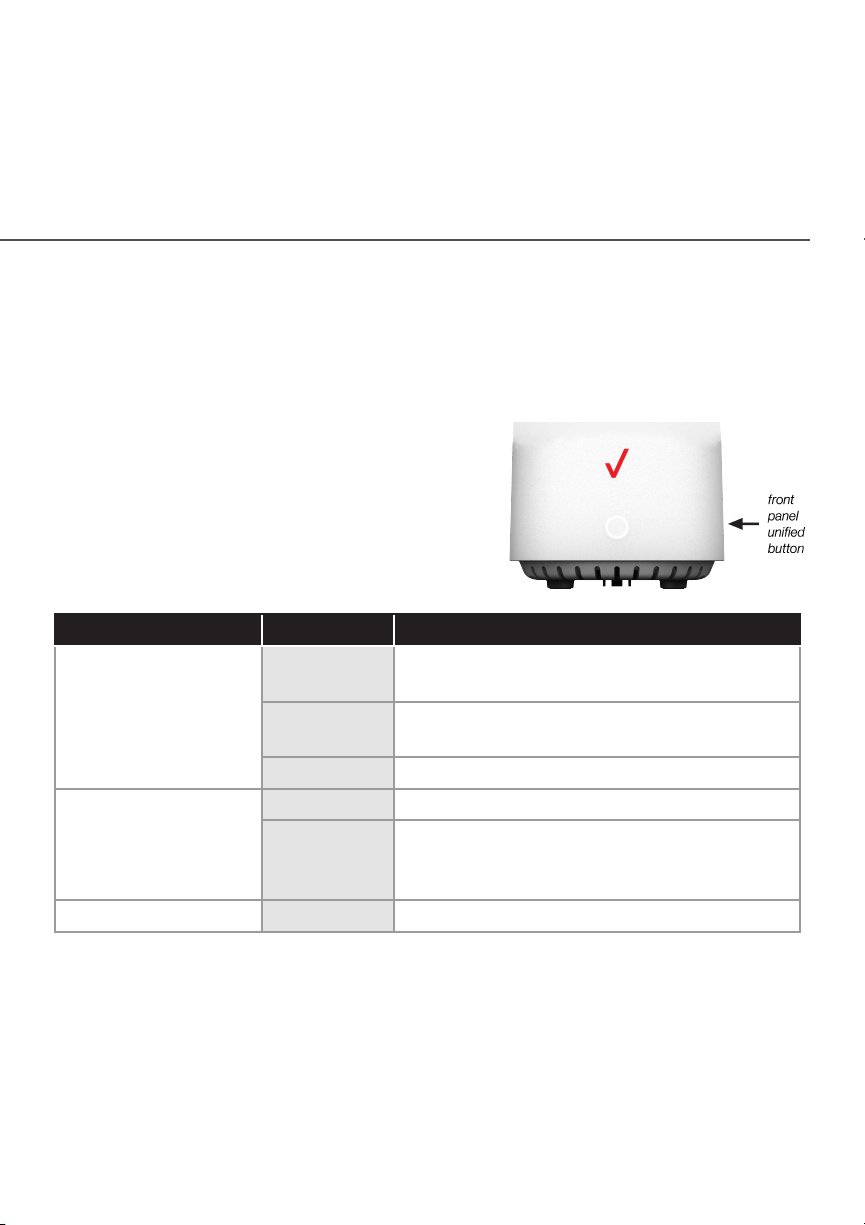
1.3a/ FRONT PANEL
The front panel’s unified button allows quick access to the Wi-Fi
Protected Setup (WPS) feature and pairing mode.
The Router Status LED will be solid
white when your Fios Router is turned
on, connected to the internet, and
functioning normally.
Router Status LED
Condition Status LED Color Fios Router
Normal WHITE Normal operation (solid)
Router is booting (fast blink)
BLUE Pairing mode (slow blink)
Pairing successful (solid)
GREEN Wi-Fi has been turned o (solid)
Issue(s) YELLOW No internet connection (solid)
RED Hardware/System failure detected (solid)
Overheating (fast blink)
Pairing Failure (slow blink)
Power OFF Power o
10
The WPS button is used to initiate Wi-Fi Protected Setup. This is an
easy way to add WPS capable devices to your Wi-Fi network. To
activate the WPS function, press and hold the unified button located
on the front of your Fios Router for more than two seconds. When
WPS is initiated from your router, the Router Status LED slowly
flashes blue for up to two minutes, allowing time to complete the
verizon.com/fios | ©2020 Verizon. All Rights Reserved
Page 11

GETTING TO KNOW YOUR FIOS ROUTER
WPS pairing process on your Wi-Fi device (also known as a Wi-Fi
client). When a device begins connecting to your router using WPS,
the Router Status LED rapidly flashes blue for a few seconds, and
turns solid blue and then solid white as the connection completes.
If there is an error during the WPS pairing process, the Router
Status LED slowly flashes red for two minutes after the error
occurs.
Refer to the “Connecting A Wi-Fi Device Using WPS” for more
details. In addition, the unified button also provides a quick view
of the operational state of the Fios Router using various colors as
indicated in the chart above. Please refer to section 9.0h for details
on the rear LEDs.
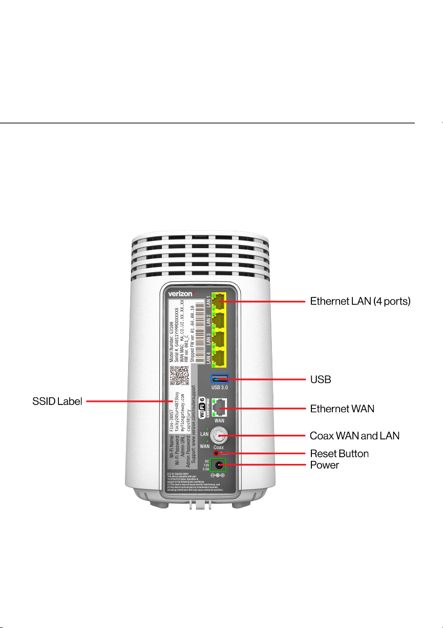
1.3b/ REAR PANEL
The rear panel of your router has a label that contains important
information about your device, including the default settings for
the Fios Router’s Wi-Fi name (SSID), Wi-Fi password (WPA2 key),
local URL for accessing the router’s administrative pages, and
administrator password. The label also contains a QR code that
you can scan with your smartphone, tablet, or other cameraequipped Wi-Fi device to allow you to automatically connect your
device to your Wi-Fi network without typing in a password (requires
a QR code reading app with support for Wi-Fi QR codes).
Page 12
/ INTRODUCTION
The rear panel has seven ports; F-type coax, Ethernet LAN (four),
Ethernet WAN, and USB. The rear panel also includes a DC power
jack and a reset button.
12
verizon.com/fios | ©2020 Verizon. All Rights Reserved
Page 13

GETTING TO KNOW YOUR FIOS ROUTER
• EEttheherrnenett L LAANN - connects devices to your Fios Router using
Ethernet cables to join the local area network (LAN). The four
Ethernet LAN ports are 10/100/1000 Mbps auto-sensing and
can be used with either straight-through or crossover Ethernet
cables.
• UUSBSB - provides up to 1000 mA at 5 VDC for attached devices.
For example, you could charge a cell phone.
• EEtthheerrnneet Wt WAN AN - connects your Fios Router to the internet using
an Ethernet cable.
• CCooaax Wx WAN aAN annd Ld LANAN - connects your router to the internet and/
or to other MoCA devices using a coaxial cable.
Warning: The WAN coax port is intended for connection to
Verizon Fios only. It must not be connected to any exterior or
interior coaxial wires not designated for Verizon Fios.
• RReesseett B Buutttotonn - allows you to reset your router to the factory
default settings. To perform a soft reboot, press and hold the
button for at least three seconds. To reset your router to the
factory default settings, press and hold the button for at least
ten seconds.
• PPoweowerr - connects your Fios Router to an electrical wall outlet
using the supplied power adapter.
Warning: The included power adapter is for home use only,
supporting voltages from 105-125 voltage in AC. Do not use in
environments with greater than 125 voltage in AC.
Page 14

/ INTRODUCTION
14
1.3c/ MOUNTING THE FIOS ROUTER TO A WALL
For optimum performance, the Fios Router is designed to stand in a
vertical upright position. Verizon does not recommend wall mounting
the Fios Router. However, if you wish to mount your Fios Router,
you can purchase a wall mount bracket from the Verizon Fios
Accessories Store at
verizon.com/home/accessories/networking-wifi
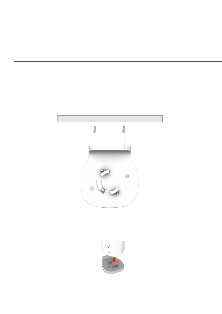
To mount your Fios Router to a wall:
1. You may use the wall-mount template sheet for positioning
the Fios Router.
2. Mark the mounting holes using the template sheet as shown
below.
verizon.com/fios | ©2020 Verizon. All Rights Reserved
Page 15
GETTING TO KNOW YOUR FIOS ROUTER
3. Drive two screws into the wall. Leave the screws extended
about 0.2 inches from the wall.
4. Verify the screws are positioned correctly by placing the wall
bracket on the screws. Then remove the wall bracket from
the wall.
5. There are two mounting slots located on the bottom of the
Fios Router. It allows you to securely attach your router to
the wall. Align the slots with the wall mount bracket.
Page 16
/ INTRODUCTION
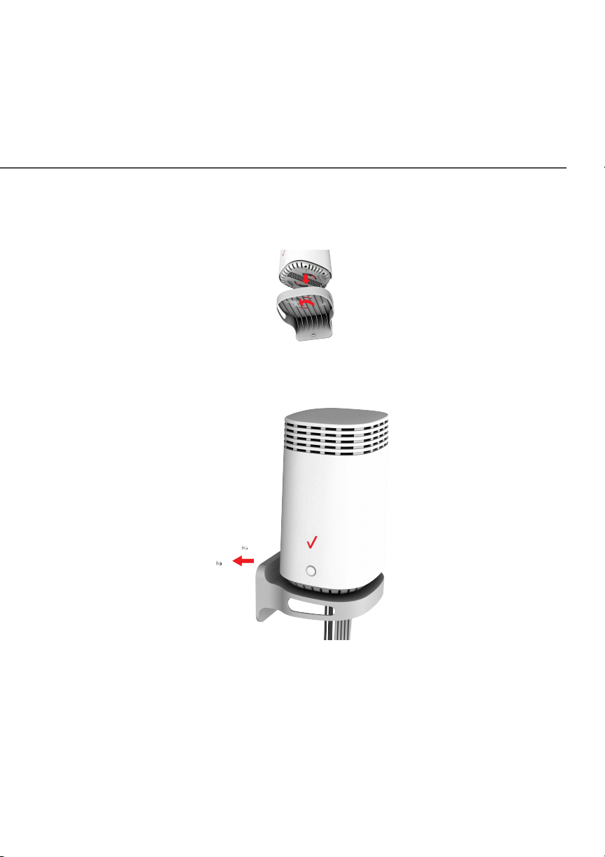
6. Attach the router to the wall mount bracket through an easy
twist and lock action.
7. Align the wall mount bracket with the attached router to the
screws, then slide the bracket down until it locks in place.
16
verizon.com/fios | ©2020 Verizon. All Rights Reserved
Page 17
GETTING TO KNOW YOUR FIOS ROUTER
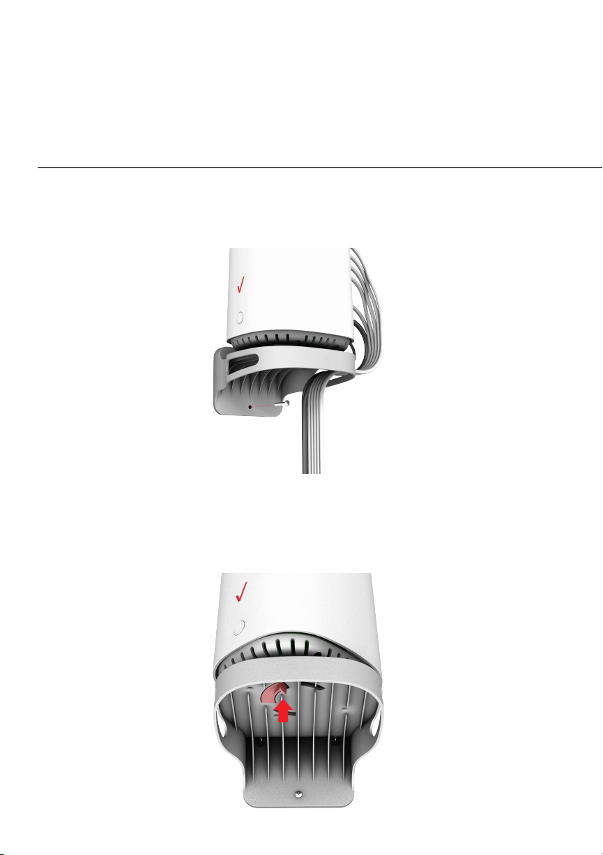
8. To secure the bracket, place one screw into the small hole of
the bracket and tighten the screw into your wall.
Note: To release the lock, twist the router counter-clockwise
and press down on the small clip on the bottom of the
bracket.
Page 18

02 /
CONNECTING YOUR FIOS ROUTER
2.0 Setting up Your Fios Router
2.1 Expanding Wi-Fi coverage
2.2 Computer Network
Configuration
2.3 Main Screen
Page 19

/ CONNECTING YOUR
FIOS ROUTER
Connecting your Fios Router and
accessing its web-based User
Interface (UI) are both simple
procedures.
Accessing the UI may vary slightly,
depending on your device’s operating
ystem and web browser.
s
19
verizon.com/fios | ©2020 Verizon. All Rights Reserved
Page 20
SETTING UP YOUR FIOS ROUTER
./ SETTING UP YOUR FIOS ROUTER
Before you begin, if you are replacing an existing router, disconnect
it. Remove all old router components, including the power supply.
They will not work with your new Fios Router.
2.0a/ INSTALLATION INSTRUCTIONS
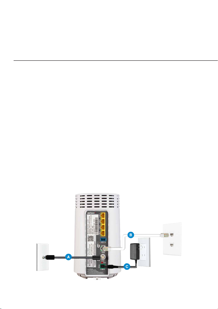
. CONNECONNECCTT Y YOUROUR C CABLEABLESS
A. Connect the coax cable from the coax port on your
router to a coax outlet. (Required for Fios TV)
B. Connect the Ethernet cable from your router’s WAN
port to an Ethernet outlet. (Required for internet speeds
greater than 100 Mbps)
C. Connect the router power cord to an electrical outlet.
Page 21
/ CONNECTING YOUR
FIOS ROUTER
D. Router will take up to 10 minutes to power up completely.
Move on when the front light is solid white.
2. CCONNEONNECCTT Y YOUROUR DEVICE DEVICESS
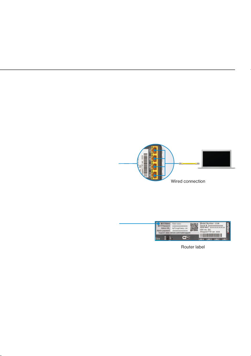
WirWired or Wi-Fied or Wi-Fi? Y? Your choiceour choice..
WirWireded
A. Connect the
Ethernet cable to
any yellow LAN port
on your router.
B. Connect the other end to your computer.
21
Wi-FiWi-Fi
A. Get the Wi-Fi name
and password o the
label on your router.
B. On your device, choose your
Wi-Fi name when it appears.
C. Enter the Wi-Fi password exactly as it is on your router
label.
verizon.com/fios | ©2020 Verizon. All Rights Reserved
Page 22

SETTING UP YOUR FIOS ROUTER
Wi-Fi NeWi-Fi Nettwworkork
The Fios Router has one Wi-Fi name supporting 2.4 GHz
and 5 GHz signals. The Self-Organizing Network (SON)
feature lets your devices move between the two signals
automatically for an optimized Wi-Fi connection.
3. CCOMPLETEOMPLETE A ACCTIVTIVAATIONTION
Activate your router by opening a web browser on your
computer and following the prompts.
2.0b/ CONFIGURE YOUR FIOS ROUTER
1. Open a web browser on the device connected to your
Fios Router network.
2. In the browser address field (URL), enter:
myfiosgateway.com, then press the EnEntterer key on your
keyboard.
Alternately, you can enter: https://192.168.1.1
The first time you access your Fios Router, an Easy Setup
Wizard displays to help step you through the setup process.
Page 23
/ CONNECTING YOUR
FIOS ROUTER
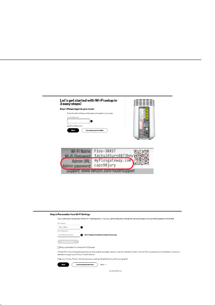
3. On the StStep 1: Pleasep 1: Please log in te log in to yo your rour routouterer screen, enter the
password that is printed next to the Admin password on the
label on the rear of your router.
23
4. Click NNexextt. The StStep 2: Pep 2: Persersonalizonalize Ye Your Wi-Fi Seour Wi-Fi Setttingstings
screen displays. Click on the check box next to SeSetup and tup and
Enable YEnable Your Guesour Guest Wi-Fi (Opt Wi-Fi (Optional)tional) to personalize your
Guest Wi-Fi Name and Password.
verizon.com/fios | ©2020 Verizon. All Rights Reserved
Page 24
SETTING UP YOUR FIOS ROUTER
For your protection, your Fios Router is pre-set at the factory to
use WPA2 (Wi-Fi Protected Access) encryption for your Wi-Fi
network. This is the best setting for most users and provides
maximum security.
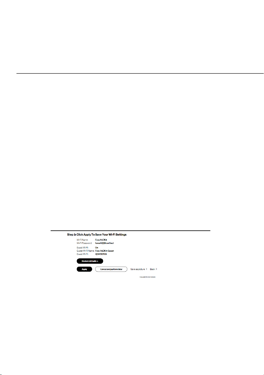
5. Click NNexextt. The StStep 3: Click Apply tep 3: Click Apply to Sao Savve Ye Your Wi-Fi our Wi-Fi
SeSetttingstings screen appears. You have an option of saving the
Wi-Fi settings as an image on your device by clicking the
SaSavve as picture as picturee button. After you click SaSavve as picture as picturee to
save your Wi-Fi settings as an image, click ApplyApply to save the
Wi-Fi changes to your Fios Router.
Important: If you are on a Wi-Fi device when setting up your
Fios Router, you will be disconnected from the Wi-Fi network
when you change the Wi-Fi name or Wi-Fi password. When this
occurs, your Fios Router will detect this situation and prompt
you to reconnect using the new settings.
Page 25
/ CONNECTING YOUR
FIOS ROUTER
25
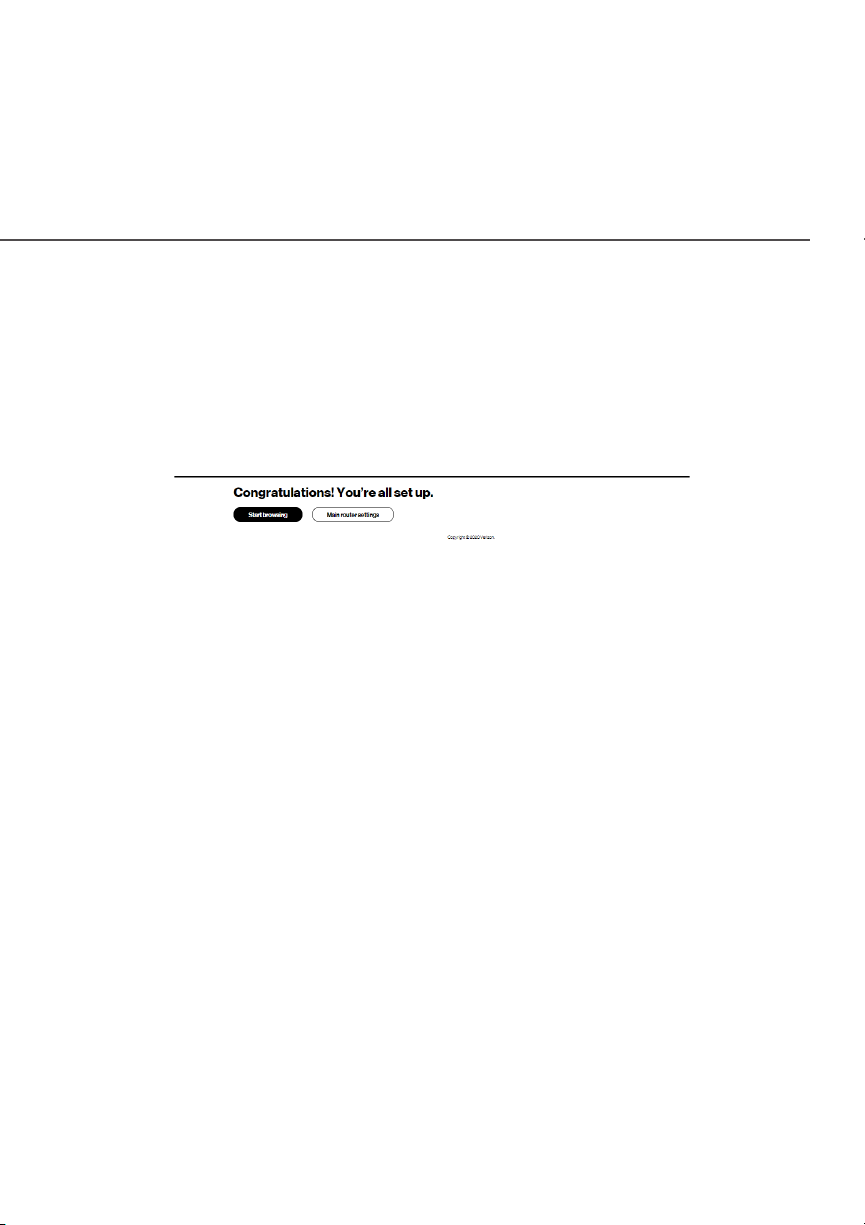
The CongrCongraatulatulations! Ytions! You’rou’re all se all seet upt up.. screen displays once
your Fios Router verifies the final settings and has successfully
connected to the internet and is ready for use. You can click on
Main router settings to access the main screen of the Fios Router
or click on Start browsing and you will be directed to the
Verizon.com website.
If your Fios Router is subsequently reset to the factory default
settings, the settings printed on the label will again be in eect.
If your Fios Router fails to connect, follow the troubleshooting steps
in the Troubleshooting section of this guide.
./ EXPANDING WIFI COVERAGE
Connecting Verizon’s Fios Extender to the Fios Router allows you
to extend Wi-Fi signal range of the Fios Router for eliminating Wi-Fi
dead zones on your Wi-Fi network.
verizon.com/fios | ©2020 Verizon. All Rights Reserved
Page 26

EXPANDING WIFI COVERAGE
2.1a/ WIFI INSTALLATION
1. Place the Fios Extender directly next to the Fios Router.
2. Connect the power cord from the extender to an electrical
outlet.
3. When the light on the extender is solid yellow, press
and hold the buttons on your router and extender for 2+
seconds until they slowly begin to blink blue.
4. The lights on the router and extender should turn solid blue
while the Wi-Fi connection is initiating and solid white when
the connection is complete.
5. Once the Wi-Fi connection is complete, you can unplug and
move the extender to an area between your router and an
area with spotty Wi-Fi coverage. Once plugged in again, the
light should turn solid white again within a few minutes.
You’re all set! Your devices will connect automatically with the
same Wi-Fi network name and password as your Fios Router.
Page 27

/ CONNECTING YOUR
FIOS ROUTER
27
2.1b/ WIRED INSTALLATION
1. Place the Fios Extender and Fios Router near a coax
outlet—ideally in an area with spotty Wi-Fi coverage.
2. Connect the coax cable from the extender to a coax outlet.
(If the coax outlet is already in use, you can use the coax
splitter included in the shipping box.)
3. Connect the power cord from the extender to an electrical
outlet.
4. The light on the extender should turn solid white within a few
minutes, indicating the connection is complete.
You’re all set! Your devices will connect automatically with the same
Wi-Fi network name and password as your Fios Router.
./ COMPUTER NETWORK CONFIGURATION
Each network interface on your computer should either
automatically obtain an IP address from the upstream Network
DHCP server (default configuration) or be manually configured with
a statically defined IP address and DNS address. We recommend
leaving this setting as it is.
verizon.com/fios | ©2020 Verizon. All Rights Reserved
Page 28

COMPUTER NETWORK CONFIGURATION
2.2a/ CONFIGURING DYNAMIC IP ADDRESSING
To configure a computer to use dynamic IP addressing:
WINDOWS 7/8
1. In the Control Panel, locate NeNettwwork and Inork and Intterneernett, then
select VieView New Nettwwork Staork Status and Ttus and Taskaskss.
2. In the VieView yw your activour active nee nettwworkorks – Connect or diss – Connect or disconnectconnect
section, click LLococal Aral Area Connectionea Connection in the Connections
field. The Local Area Connection Status window displays.
3. Click PrPropertiesoperties. The Local Area Connection Properties
window displays.
4. Select InIntterneernet Prt Proottocol Vocol Version 4 (ersion 4 (TTCPCP/IP/IPv4)v4), then click
PrPropertiesoperties. The Internet Protocol Version 4 (TCP/IPv4)
Properties window displays.
5. Click the ObObtain an IP addrtain an IP address autess automaomaticticallyally radio button.
6. Click the ObObtain DNS stain DNS serverver addrer address autess automaomaticticallyally radio
button, then click OKOK.
7. In the Local Area Connection Properties window, click OKOK
to save the settings.
8. To configure Internet Protocol Version 6 (TCP/IPv6) to use
dynamic IP addressing, repeat steps 1 to 7. However for
step 4, select InIntterneernet Prt Proottocol Vocol Version 6 (ersion 6 (TTCPCP/IP/IPv6) v6) in
the
Pr Propertiesoperties option (refer to IPv6 section for Fios Router
configuration).
Page 29

/ CONNECTING YOUR
FIOS ROUTER
WINDOWS 10
1. On the Windows desktop, click on the StartStart icon. Select
SeSetttingstings and click NeNet
2. In the Network & Internet, click EEthernethernett.
3. Select NeNettwwork and Sharing Cenork and Sharing Centterer. The VieView yw your basicour basic
nenettwwork inork infformaormation and stion and seet up connectionst up connections window
displays.
4. In the VieView yw your activour active nee nettwworkorkss, click EEthernethernett in the
Connections Connections field. The EEthernethernet Stat Statustus window displays.
5. Click PrPropertiesoperties. The EEthernethernet Prt Propertiesoperties window displays.
6. Select InIntterneernet Prt Proottocol Vocol Version 4 (ersion 4 (TTCPCP/IP/IPv4)v4), then click
PrPropertiesoperties. The InIntterneernet Prt Proottocol Vocol Version 4 (ersion 4 (TTCPCP/IP/IPv4)v4)
PrPropertiesoperties window displays.
twwork & Inork & Intterneernett.
29
7. Click the ObObtain an IP addrtain an IP address autess automaomaticticallyally radio button.
8. Click the ObObtain DNS stain DNS serverver addrer address autess automaomaticticallyally radio
button, then click OKOK.
9. In the LLococal Aral Area Connection Prea Connection Properties operties window, click OK OK to
save the settings.
10. To configure Internet Protocol Version 6 (TCP/IPv6) to
use dynamic IP addressing, repeat steps 1 to 9. However
for step 6, select InIntterneernet Prt Proottocol Vocol Version 6 (ersion 6 (TTCPCP/IP/IPv6)v6) in
the Pr Propertiesoperties option (refer to IPv6 section for Fios Router
configuration).
verizon.com/fios | ©2020 Verizon. All Rights Reserved
Page 30

COMPUTER NETWORK CONFIGURATION
MACINTOSH OS X
1. Click the AppleApple icon in the top left corner of the desktop. A
menu displays.
2. Select
window displays.
SySyssttem Prem Preeffererencesences. The System Preferences
3. Click
4. Verify that
highlighted and displays
5. Click AAssisssist Met Me.
6. Follow the instructions in the Network Diagnostics
Assistant.
2.2b/ CONNECTING OTHER COMPUTERS AND NETWORK
NeNettwworkork.
EEthernethernett, located in the list on the left, is
ConnectConnecteded.
DEVICES
You can connect your Fios Router to other computers or set top
boxes using an Ethernet cable, Wi-Fi connection (Wi-Fi), or coaxial
cable.
ETHERNET
1. Plug one end of an Ethernet cable into one of the open
yellow Ethernet ports on the back of your Fios Router.
2. Plug the other end of the Ethernet cable into an Ethernet
port on the computer.
Page 31

/ CONNECTING YOUR
FIOS ROUTER
3. Repeat these steps for each computer to be connected to
your Fios Router using Ethernet. You can connect up to four.
31
CONNECTING A WIFI DEVICE USING WPS
Wi-Fi Protected Setup (WPS) is an easier way for many devices
to set up a secure Wi-Fi network connection. Instead of manually
entering passwords or multiple keys on each Wi-Fi client, such as
a laptop, printer, or external hard drive, your Fios Router creates a
secure Wi-Fi network connection.
In most cases, this only requires the pressing of two buttons – one
on your Fios Router and one on the Wi-Fi client. This could be either
a built-in button or one on a compatible Wi-Fi adapter/card, or a
virtual button in software. Once completed, this allows Wi-Fi clients
to join your Wi-Fi network.
To initialize the WPS process, you can either press and hold the
unified button located on the front of your Fios Router for more
than two seconds or use the UI and press the on-screen button.
You can easily add Wi-Fi devices to your Wi-Fi network using the
WPS option if your Wi-Fi device supports the WPS feature.
To access WPS using the user interface:
1. From the main menu, select Wi-FiWi-Fi settings, then select Wi-FiWi-Fi
PrProottectected Seed Setup (tup (WPS)WPS).
verizon.com/fios | ©2020 Verizon. All Rights Reserved
Page 32

COMPUTER NETWORK CONFIGURATION
2. Enable the protected setup by moving the selector to OnOn.
3. Use one of the following methods:
• If your Wi-Fi client device has a WPS button, press the
unified button on your Router for more than two seconds,
then click the WPS button on your Wi-Fi device (client) to
start the WPS registration process.
• If your client device has a WPS PIN, locate the PIN
printed on the client’s label or in the client documentation.
Enter the PIN number in the ClienClient WPS PINt WPS PIN field. The
ClienClient WPS PINt WPS PIN field is located in the section 2 - PIN 2 - PIN
enrenrollmenollmentt on the user interface.
• Click RRegisegistterer.
• Alternatively, you can enter the Router’s PIN shown on
this screen into the WPS user interface of your device, if
this PIN mode is supported by your Wi-Fi device.
Page 33

/ CONNECTING YOUR
FIOS ROUTER
4. After pressing the unified button (WPS) on your Router, you
have two minutes to press the WPS button on the client
device before the WPS session times out.
When the unified button (WPS) on your Router is pressed,
the Router Status LED on the front of your Router begins
flashing blue. The flashing continues until WPS pairing to the
client device completes successfully. At this time, the Router
Status LED turns solid blue.
If WPS fails to establish a connection to a Wi-Fi client device
within two minutes, the Router Status LED on your Router
flashes red for two minutes to indicate the WPS pairing
process was unsuccessful. After flashing red, the light
returns to solid white to indicate that Wi-Fi is on.
33
Note: Wi-Fi Protected Setup (WPS) cannot be used if WPA3
security is enabled or SSID broadcast is disabled or if MAC
address authentication is enabled with an empty white list.
CONNECTING A WI-FI DEVICE USING A PASSWORD
1. Verify each device that you are connecting with Wi-Fi has
built-in Wi-Fi or an external Wi-Fi adapter.
2. Open the device’s Wi-Fi settings application.
3. Select your Fios Router’s Wi-Fi network name (SSID) from
the device’s list of discovered Wi-Fi networks.
verizon.com/fios | ©2020 Verizon. All Rights Reserved
Page 34

MAIN SCREEN
4. When prompted, enter your Fios Router’s Wi-Fi password
(WPA2 or WPA3 key) into the device’s Wi-Fi settings. Your
Router’s default Wi-Fi network name and password are
located on the sticker on the rear panel of your Fios Router.
5. Verify the changes were implemented by using the device’s
web browser to access a site on the internet.
6. Repeat these steps for every device that you are connecting
with Wi-Fi to your router.
COA X
1. Verify all coax devices are turned o.
2. Disconnect any adapter currently connected to the coaxial
wall jack in the room where your router is located.
3. Connect one end of the coaxial cable to the coaxial wall
jack and the other end to the coax port on your network
device.
4. Power up the network device.
./ MAIN SCREEN
When you log into your router, the dashboard main page displays
the main navigation menu of connection status, Wi-Fi settings,
network settings, parental control, firewall security level, and
advanced quick links.
Page 35

2.3a/ Menu
/ CONNECTING YOUR
FIOS ROUTER
35
The main menu contains the following configuration options and
chapters:
• Status - this chapter
• Wi-Fi - Chapter 3
• Network - Chapter 4 and Chapter 5
• Parental Controls - Chapter 6
• Firewall - Chapter 7
• Advanced - Chapter 8
verizon.com/fios | ©2020 Verizon. All Rights Reserved
Page 36

MAIN SCREEN
2.3b/ S TAT U S
Router Status
This section displays firmware and hardware version numbers,
and the status of your router’s local network (LAN) and internet
connection (WAN).
Page 37

03 /
WIFI SETTINGS
3.0 Overview
3.1 Wi-Fi Status
3.2 Basic Settings
3.3 Advanced Settings
3.4 Channel Settings
3.5 Guest Network
Page 38

/ WIFI SETTINGS
38
Wi-Fi networking enables you to free
yourself from wires, making your devices
more accessible and easier to use.
You can create a Wi-Fi network,
including accessing and configuring
Wi-Fi security options.
verizon.com/fios | ©2020 Verizon. All Rights Reserved
Page 39

OVERVIEW
./ OV
Your Fios Router provides you with Wi-Fi connectivity using the
802.11a, b, g, n, ac or ax standards. These are the most common
Wi-Fi standards.
802.11b has a maximum data rate of 11 Mbps, 802.11a and 802.11g
have a maximum data rate of 54 Mbps, 802.11n has a maximum
data rate of 450 Mbps, 802.11ac has a maximum data rate of 3.12
Gbps, and 802.11ax has a maximum data rate of 4.8 Gbps.
802.11b and g standards operate in the 2.4 GHz range. 802.11ac
operates in the 5 GHz range. 802.11n and ax operate in both the
2.4 GHz and 5 GHz ranges.
Note:
Even one
entire Wi-Fi network.
ERVIEW
802.11a,
such
802.11b
device connected to the network will slow your
are
legacy modes and
are
not recommended.
The Wi-Fi service and Wi-Fi security are activated by default.
The level of security is preset to WPA2 encryption using a unique
default WPA2 key (also referred to as a passphrase or password)
pre-configured at the factory. This information is displayed on a
sticker located on the rear of your router.
Your router integrates multiple layers of security. These include
Wi-Fi Protected Access (WPA/WPA2), and firewall.
Page 40

/ WIFI SETTINGS
40
./ WIFI STATUS
Use the Wi-Fi status feature to view the status of your router’s Wi-Fi
network.
To view the status:
1. Access the dashboard main page. You can quickly view your
router’s Wi-Fi status in the Wi-FiWi-Fi column.
2. In the Wi-FiWi-Fi column for Primary NePrimary Nettwworkork and GuesGuest Net Nettwworkork,
the following information displays:
• ON/ON/OFFOFF - displays whether the Wi-Fi radio is active.
When the radio is not enabled, no Wi-Fi devices will be
able to connect to the home network.
• Wi-Fi Name (Wi-Fi Name (SSID)SSID) - displays the SSID (Service Set
Identifier) shared among all devices on a Wi-Fi network.
The SSID is the network name. All devices must use the
same SSID.
• Wi-Fi PWi-Fi Passasswworordd - displays the Pre-Shared Key of the
Wi-Fi security.
verizon.com/fios | ©2020 Verizon. All Rights Reserved
Page 41

BASIC SETTINGS
./ BASIC SETTINGS
You can configure the basic security settings for either 2.4 GHz or
5 GHz of your Wi-Fi network.
To configure the basic security radio, SSID and security settings:
1. Select Wi-Fi from the left pane, and then click Basic Basic
SeSetttingstings.
2. To activate the Wi-Fi radio, click the OnOn radio button.
3. If desired, enter a new name for the Wi-Fi network in
the SSID field or leave the default name that displays
automatically.
4. To activate the Wi-Fi security, click the WPWPA2 A2 or WPWPA3A3 radio
button.
5. Enter the PSK (Pre-Shared Key) password.
6. Click SaSavve Changese Changes to save the changes.
Page 42

/ WIFI SETTINGS
42
./ ADVANCED SETTINGS
You can change your advanced Wi-Fi security settings, such as
disable your SSID broadcast to secure your Wi-Fi trac; stop
your Fios Router from broadcasting your SSID; set Wi-Fi MAC
authentication to limit access to specific Wi-Fi devices; and change
the Wi-Fi mode to limit or allow access to your Wi-Fi network based
on the type of technology as well as other advanced Wi-Fi options.
verizon.com/fios | ©2020 Verizon. All Rights Reserved
Page 43

ADVANCED SETTINGS
3.3a/ BROADCAST
You can configure the Fios Router’s SSID broadcast capabilities
to allow or disallow Wi-Fi devices from automatically using a
broadcast SSID name to detect your router Wi-Fi network.
1. Select Wi-FiWi-Fi from the left pane, and then click AAdvdvanced anced
SeSetttingstings.
2. To enable SSID broadcasting, click the EnableEnable radio button.
SSID broadcast is enabled by default. The SSID of the Wi-Fi
network will be broadcast to all Wi-Fi devices.
To disable SSID broadcasting, click the DisDisableable radio button.
The public SSID broadcast will be hidden from all Wi-Fi
devices. You will need to manually configure additional Wi-Fi
devices to join the Wi-Fi network.
3. When all changes are complete, click SaSavve Changese Changes to save
the changes.
3.3b/ MAC AUTHENTICATION
You can configure your router to limit access to your Wi-Fi
network allowing access only to those devices with specific MAC
addresses.
To set Wi-Fi MAC authentication:
1. To enable access control, select the Enable AEnable Access Lisccess Listt
check box.
Page 44

/ WIFI SETTINGS
44
2. Select either:
• AAccepccept all det all devices lisvices listted beloed beloww – allows only the listed
devices to access the Wi-Fi network.
Warning: This will block Wi-Fi network access for all devices not
in the list. Only devices in the list will be able to connect to the
Wi-Fi network.
• DenDeny all dey all devices lisvices listted beloed beloww – denies access to the listed
devices. All other Wi-Fi devices will be able to access the
Wi-Fi network if they use the correct Wi-Fi password.
3. Enter the MAC address of a device, then click the AAdd dd
button.
4. Repeat step 2 and step 3 to add additional devices, as
needed.
5. To remove a specific device’s MAC address, click the
RReemmoveove button next to the specific MAC address.
6. When all changes are complete, click SaSavve Changese Changes to save
the changes.
verizon.com/fios | ©2020 Verizon. All Rights Reserved
Page 45

ADVANCED SETTINGS
3.3c/ 802.11 MODE
From the 802.11 Mode page, you can limit the Wi-Fi access to your
network by selecting the 2.4 GHz and 5 GHz Wi-Fi communication
standard (mode) best suited or compatible with the devices you
allow access to your Wi-Fi network.
Select the Wi-Fi mode as follows:
• Compatibility – This is the default mode setting on 5 GHz,
providing a good balance of performance and interoperability
with existing Wi-Fi devices. 802.11a,n,ac and ax devices can
connect.
• Legacy – This is the default mode setting on 2.4 GHz, providing
broad connection support for old and new Wi-Fi devices. Only
802.11b,g and n devices can connect.
• 802.11n is available on both 2.4 GHz and 5 GHz frequencies.
• Connecting 802.11a or b devices will cause your Wi-Fi network
to slow on that radio and is not recommended.
• When all changes are complete, click
changes.
SaSavve Changese Changes to save the
Page 46

/ WIFI SETTINGS
46
3.3d/ OTHER ADVANCED WIFI OPTIONS
You can view additional Wi-Fi options.
Comment: Recommend leaving defaults as is unless otherwise
directed.
View the following options:
Caution: These settings should only be configured by
experienced network technicians. Changing the settings could
adversely aect the operation of your router and your local
network.
• SON Wi-Fi Enabled - allows for smart roaming to provide
reliable Wi-Fi network with full signal strength in all areas.
• Group key update – to update the WPA shared key, click
the EnableEnable checkbox.
• Interval time – time interval used to update the WPA
shared key (used to generate the group key).
• Transmit Power – adjusts the power of the Wi-Fi signal.
• Wi-Fi QoS (WMM) - improves the quality of service
(QoS) for voice, video, and audio streaming over Wi-Fi by
prioritizing these data streams.
• WMM Power Save - improves battery life on mobile Wi-Fi
devices such as smart phones and tablets by fine-tuning
power consumption.
Important: WMM (Wi-Fi Multimedia) QoS and Power Save require
a Wi-Fi client device which also supports WMM.
verizon.com/fios | ©2020 Verizon. All Rights Reserved
Page 47

CHANNEL SETTINGS
./ CHANNEL SETTINGS
You can configure the channel settings for either 2.4 GHz or
5 GHz of your Wi-Fi network.
Page 48

/ WIFI SETTINGS
48
On the Channel SeChannel Setttingstings page for either 2.4 GHz or 5 GHz, the
following information displays:
• ChannelChannel - this is the radio channel used by the Wi-Fi router and
its clients to communicate with each other. The channel must be
the same on the router and all of its Wi-Fi clients.
– Select the channel you want the Wi-Fi radio to use to
communicate, or accept the default AAututomaomatictic channel
selection. Then the router will automatically assign itself a
radio channel.
– Select the KKeep meep my channel sy channel selection during poelection during powwer cyer cyclecle
check box to save your channel selection when your
Fios Router is rebooted.
verizon.com/fios | ©2020 Verizon. All Rights Reserved
Page 49

CHANNEL SETTINGS
– DFS Channels are enabled by default during channel scans.
To disable DFS scan uncheck the DFS option.
Note: DFS channels are a subset of the 5 GHz network that
is shared with radar systems. Some consumer devices do
not support these channels and cannot connect to routers
using them. Examples include some media streaming devices.
Disabling this feature will allow the router to select the best
available channel to broadcast on and allow these devices to
connect.
• Channel WidthChannel Width - displays the Wi-Fi channel currently in use on
each band. Default setting is “Au
available non-DFS channels. On 5 GHz, the DFS channels
range from 52-144.
• Channel AnalyChannel Analyzzerer - displays the analysis of channel availability.
Click PPerferform Neorm New Scw Scanan to perform channel availability scan
for the Fios Router accommodating the best radio channel and
providing the best Wi-Fi performance.
Auttoo”, users can select from
• Channel ScorChannel Scoree - scans and displays a network congestion
score of one to ten in each Wi-Fi channel. It can be used to
determine which channels to use or to avoid. Higher score
indicates less congestion in a channel.
• Channel AnalyChannel Analysissis - scans and displays channel bandwidth and
signal strength of available APs.
Page 50

/ WIFI SETTINGS
50
./ GUEST NETWORK
The GuesGuest Net Nettwworkork is designed to provide internet connectivity
to your guests but restricts access to your primary network and
shared files. The primary network and the guest network are
separated from each other through firewalls. You create one Guest
Wi-Fi SSID and one password, and use it for all guests. GuesGuest Wi-Fi t Wi-Fi
can be managed using either the Fios Router’s web interface, or via
the Verizon MyFios app. The guest network SSID does not change
when you make a change to your primary network SSID.
The Fios Router is shipped from the factory with Guest
Wi-Fi turned o. The default SSID for Guest Wi-Fi is preconfigured
at the factory to the default Wi-Fi network name (SSID) which is
displayed on a sticker located at the rear of the router followed by
hyphen guest (-Guest). For example – if the router is shipped with a
default SSID of “Fios-ABCDE” then the default SSID for Guest Wi-Fi
is “Fios-ABCDE-Guest”.
verizon.com/fios | ©2020 Verizon. All Rights Reserved
Page 51

GUEST NETWORK
3.5a/ GUEST WI-FI
To enable Guest Wi-Fi:
1. From the main menu, select Wi-FiWi-Fi, then select GuesGuest t
NeNettwworkork.
2. Click the OnOn radio button and enter a valid SSIDSSID and
PPassasswworordd.
3. Press
Important: It is not recommended to create a guest network
without a password.
SaSavve Changese Changes to save the changes.
3.5b/ GUEST WIFI DEVICES
The devices on the GuesGuest Net Nettwworkork can be viewed on the GuesGuest t
Wi-Fi deWi-Fi device lisvice listt. If the admin toggles the button next to a device to
OO, that device will be blocked from accessing the internet.
Refer to “Connecting A Wi-Fi Device Using WPS” on page 31
for the Wi-Fi Protected Setup (WPS) setup.
Page 52

04 /
CONFIGURING NETWORK SETTINGS
4.0 Accessing Network Settings
4.1 Using Network Settings
Page 53

/ CONFIGURING
NETWORK SETTINGS
You can configure the basic network
settings for your Fios Router’s network.
53
verizon.com/fios | ©2020 Verizon. All Rights Reserved
Page 54

ACCESSING NETWORK SETTINGS
Caution: The settings described in this chapter should only be
configured by experienced network technicians. Changes could
adversely aect the operation of your router and your local
network.
./ ACCESSING NETWORK SETTINGS
The NeNettwworkork section allows you to view and manage your network
connections and devices. You can block websites and internet
services, set port forwarding, view device details, and rename
devices.
4.0a/ NETWORK STATUS
To view your network connections:
Select NeNettwworkork from the left pane, and then click NeNettwwork sork statatustus.
Page 55

/ CONFIGURING
NETWORK SETTINGS
55
– To view and edit the details of a specific network connected
device, click the hyperlinked name from the DeDevice opvice optionstions
drop-down menu.
– To filter the network connected device, click the drop down
menu
and select one of the options.
– To remove all inactive network connections, click the RReefrfresh esh
HosHostt option at the bottom of the list.
The following sections detail the types of network connection
settings that you can view and configure.
./ USING NETWORK SETTINGS
You can access and configure common network parameters:
• Block this DeBlock this Devicevice/Un-Block this DeUn-Block this Devicevice - Click this option
to quickly enable/disable a device from having internet
access.
• WWebsitebsite Blockinge Blocking - To block specific websites, click
Website Blocking. The Parental Controls page displays.
For additional information about blocking websites, refer
to Chapter 6 Setting Parental Controls.
verizon.com/fios | ©2020 Verizon. All Rights Reserved
Page 56

USING NETWORK SETTINGS
• Block InBlock Intterneernet Servicest Services - Internet services blocking
prevents a device on your network from accessing
specific services, such as receiving email or downloading
files from FTP sites. Block Internet services by locating
the device, then clicking Block Internet Services. The
Access Control page displays. For additional information
on blocking internet services, refer to the Access Control
section in Chapter 7 Configuring Security Settings.
• PPort Fort Forworwarardingding - Port Forwarding allows your network
to be exposed to the internet in specific limited and
controlled ways. For example, you could allow specific
applications, such as gaming, voice, and chat, to
access servers in the local network. To access the Port
Forwarding page, click Port Forwarding.
For additional information, refer to the Port Forwarding
section in Chapter 7 Configuring Security Settings.
• VieView Dew Device Device Detailstails - Click View Device Details to display
the Device Information page and view the selected
device’s information, such as IP Address, MAC address,
Network Connection, Lease Type, Port Forwarding
Services, as well as the Ping TPing Tesestt option.
• RRename this Deename this Devicevice - To change the name of a specific
device, click Rename this Device. The Rename Device
page displays. If desired, enter the new device name and/
or select a dierent icon. Click ApplyApply to save changes.
The Network status page will open with the new name
and icon displayed.
Page 57

05 /
USING NETWORK CONNECTIONS
5.0 Accessing Network
Connections
5.1 Network (Home/Oce)
Connection
5.2 Wi-Fi Access Point Connection
5.3 Ethernet Connection
5.4 Broadband Connection
(Ethernet/Coax)
Page 58

/ USING NETWORK
CONNECTIONS
58
Your Fios Router supports various local
area network (LAN) and wide area
network (WAN), or internet connections
using Ethernet or coaxial cables.
You can configure aspects of the
network and internet connections as
well as create new connections.
verizon.com/fios | ©2020 Verizon. All Rights Reserved
Page 59

ACCESSING NETWORK CONNECTIONS
Caution: The settings described in this chapter should only be
configured by experienced network technicians. Changes could
adversely aect the operation of your router and your local
network.
./ ACCESSING NETWORK CONNECTIONS
You can access your network connections and view the
connections by connection type.
To access the network connections:
1. Select NeNettwworkork, then select NeNettwwork Connectionsork Connections.
2. To display all connection entries, click the AAdvdvancedanced button.
Page 60

/ USING NETWORK
CONNECTIONS
60
3. To view and edit the details of a specific network connection,
click the hyperlinked name or the action icon. The following
sections detail the types of network connections that you
can view.
./ NETWORK HOME/OFFICE CONNECTION
You can view the properties of your local network. This connection
is used to combine several network interfaces under one virtual
network. For example, you can create a home/oce network
connection for Ethernet and other network devices.
Note: When a network connection is disabled, the underlying
devices formerly connected to it will not be able to obtain a new
DHCP address from that Fios Router network interface.
To view the connection:
1. On the NeNettwwork Connectionsork Connections page, click the NeNettwwork ork
(Home/(Home/Oce)Oce) connection link. The NeNettwwork (Home/ Oce) ork (Home/ Oce)
PrPropertiesoperties page displays.
verizon.com/fios | ©2020 Verizon. All Rights Reserved
Page 61

NETWORK HOME/OFFICE CONNECTION
2. To rename a network connection, enter the new network
name in the NameName field.
3. Click ApplyApply to save the changes.
5.1a/ CONFIGURING THE HOME/OFFICE NETWORK
To configure the network connection:
1. In the NeNettwwork (Home/ork (Home/Oce) PrOce) Propertiesoperties page, click
SeSetttingstings. The configuration page displays.
Page 62

/ USING NETWORK
CONNECTIONS
62
2. Configure the following sections, as needed.
verizon.com/fios | ©2020 Verizon. All Rights Reserved
Page 63

NETWORK HOME/OFFICE CONNECTION
GENERAL
In the GenerGeneralal section, verify the following information:
StaStatustus - displays the connection status of the network.
•
•
NeNettwworkork – displays the type of network connection.
• Connection TConnection Typeype - displays the type of connection
interface.
• PhPhyysicsical Aal Addrddressess - displays the physical address of the
network card used for the network.
MTUMTU - displays the Maximum Transmission Unit (MTU)
•
indicating the largest packet size permitted for internet
transmissions:
– AAututomaomatictic: sets the MTU (Maximum Transmission
Unit) at 1500.
–
AAututomaomatic btic by DHCPy DHCP: sets the MTU according to the
DHCP connection.
– ManualManual: allows you to manually set the MTU.
InIntterneernet Prt Proottocolocol
•
In the Internet Protocol section, specify one of the
following:
– No IPNo IPv4 Av4 Addrddressess: the connection has no IP address.
This is useful if the connection operates under a
bridge.
–
ObObtain an IPtain an IPv4 Av4 Addrddress Aess Aututomaomaticticallyally: the network
connection is required by Verizon to obtain an IP
address automatically. The server assigning the IP
Page 64

/ USING NETWORK
CONNECTIONS
64
address also assigns a subnet mask address, which
can be overridden by entering another subnet mask
address.
– UsUse the Fe the Folloollowing IP Awing IP Addrddressess: the network connection
uses a permanent or static IP addrIP addressess and SubneSubnet t
MaskMask address, provided by Verizon or experienced
network technician.
BRIDGE
In the BridgeBridge section of the NeNettwwork (Home/ork (Home/Oce) PrOce) Propertiesoperties, you
can configure the various LAN interfaces.
Caution: Do not change these settings unless specifically instructed
to by Verizon. Changes could adversely aect the operation of your
Fios Router and your local network.
Verify the following information:
• StaStatustus – displays the connection status of a specific
network connection.
• AActionction – contains an EEditdit hyperlink that, when clicked,
generates the next level configuration page for the
specific network connection or network device.
verizon.com/fios | ©2020 Verizon. All Rights Reserved
Page 65

NETWORK HOME/OFFICE CONNECTION
IP ADDRESS DISTRIBUTION
The IP AIP Addrddress Disess Distributiontribution section is used to configure the
Dynamic Host Configuration Protocol (DHCP) server parameters of
your Fios Router.
Once enabled and configured, the DHCP server automatically
assigns IP addresses to any network devices which are set to
obtain their IP address dynamically.
If DHCP Server is enabled on your Fios Router, configure the
network devices as DHCP Clients. There are 2 basic options in this
section: DisDisabledabled and DHCP ServDHCP Serverer.
To set up the Fios Router’s network bridge to function as a DHCP
server:
1. In the IP AIP Addrddress Disess Distributiontribution section, select the DHCP DHCP
sserververer. Once enabled, the DHCP server provides automatic
IP assignments (also referred to as IP leases) based on the
preset IP range defined below.
• Start IP AStart IP Addrddressess – Enter the first IP address in the IP
range that the Fios Router will automatically begin
assigning IP addresses from. Since your Fios Router’s
IP address is 192.168.1.1, the default Start IP Address is
192.168.1.2.
• End IP AEnd IP Addrddressess – Enter the last IP address in the IP
range that the Fios Router will automatically stop the
IP address allocation at. The maximum end IP address
range that can be entered is 192.168.1.254.
Page 66

/ USING NETWORK
CONNECTIONS
2. If Windows Internet Naming Service (WINS) is being used,
enter the WINS ServWINS Serverer address.
3. In the LLeasease Time in Minute Time in Minuteses field, enter the amount of time a
network device is allowed to connect to the Fios Router with
its currently issued dynamic IP address.
4. Click ApplyApply to save changes.
IP ADDRESS DISTRIBUTION ACCORDING TO DHCP OPTION
VENDOR CLASS IDENTIFIER
DHCP vendor class is related to DHCP option 60 configuration
within the router. Adding option 60 configurations allows for
particular vendor to get lease from a specified pool of address.
66
ROUTING TABLE
You can configure your Fios Router to use static or dynamic routing.
• StaStatic rtic routingouting – specifies a fixed routing path to neighboring
destinations based on predetermined metrics.
• Dynamic rDynamic routingouting – automatically adjusts how packets travel on
the network. The path determination is based on network/device
reachability and status of network being traveled.
To configure routing:
1. In the RRouting Touting Tableable section, click AAdd nedd new rw routoutee button to
display and modify the new route configuration page.
verizon.com/fios | ©2020 Verizon. All Rights Reserved
Page 67

WIFI ACCESS POINT CONNECTION
2. To save your changes click ApplyApply.
./ WIFI ACCESS POINT CONNECTION
A Wi-Fi Access Point network connection allows Wi-Fi devices to
connect to the local area network (LAN) using the 2.4 GHz or
5 GHz Wi-Fi network.
Note: Once disabled, all Wi-Fi devices connected to that Wi-Fi
network will be disconnected from the LAN network and internet.
To view the connection settings:
1. In the NeNettwwork Connectionsork Connections page, click the NeNettwwork(Home/ork(Home/
Oce)Oce) connection link.
2. To access the 5.5.0GHz Wi-Fi A0GHz Wi-Fi Access Pccess Poinoint 1 Prt 1 Propertiesoperties or
2.2.4GHz Wi-Fi A4GHz Wi-Fi Access Pccess Poinoint 2 Prt 2 Propertiesoperties page, click the
5.5.0GHz Wi-Fi A0GHz Wi-Fi Access Pccess Poinoint 1 t 1 or 2.2.4GHz Wi-Fi A4GHz Wi-Fi Access ccess
PPoinoint 2t 2 link listed under the Underlying DeUnderlying Devicevice section.
Page 68

/ USING NETWORK
CONNECTIONS
3. To disable the connection, click the DisDisableable button.
4. To rename the connection, enter a name in the NameName field.
68
5. Click ApplyApply to save the changes.
6. Reboot your Fios Router.
5.2a/ CONFIGURING Wi-Fi ACCESS POINT PROPERTIES
To configure the connection:
1. In the 5.5.0GHz Wi-Fi A0GHz Wi-Fi Access Pccess Poinoint 1 Prt 1 Propertiesoperties or 2.2.4GHz 4GHz
Wi-Fi AWi-Fi Access Pccess Poinoint 2 Prt 2 Propertiesoperties page, click SeSetttingting. The
configuration page displays.
verizon.com/fios | ©2020 Verizon. All Rights Reserved
Page 69

WIFI ACCESS POINT CONNECTION
2. Verify the following information:
• StaStatustus - displays the connection status of the network.
• NeNettwworkork – displays the type of network connection.
• Connection TConnection Typeype - displays the type of connection
interface.
• PhPhyysicsical Aal Addrddressess - displays the physical address of the
network card used for the network.
• MTUMTU - specifies the largest packet size permitted for
internet transmissions:
– AAututomaomatictic: set the MTU (Maximum Transmission
Unit) at 1500.
– AAututomaomatic btic by DHCPy DHCP: sets the MTU according to the
DHCP connection.
– ManualManual: allows you to manually set the MTU.
3. Click ApplyApply to save changes.
Page 70

/ USING NETWORK
CONNECTIONS
70
./ ETHERNET CONNECTION
You can view the properties of your Ethernet LAN connection using
an Ethernet cable inserted into one of your Fios Router’s Ethernet
LAN ports.
To view the connection settings:
1. In the NeNettwwork Connectionsork Connections page, click the NeNettwwork(Home/ork(Home/
Oce)Oce) connection link.
2. Next, to access the
EEthernethernet Prt Propertiesoperties page, click the
EEthernethernett link listed under the Underlying DeUnderlying Devicevice section.
3. To rename the network connection, enter the new name in
the
NameName field.
4. Click ApplyApply to save changes.
verizon.com/fios | ©2020 Verizon. All Rights Reserved
Page 71

ETHERNET CONNECTION
5.3a/ CONFIGURING ETHERNET PROPERTIES
To configure the connection:
1. In the EEthernethernet Prt Propertiesoperties page, click SeSetttingstings. The
configuration page displays.
2. Configure the following settings, as needed.
GENERAL
Verify the following information:
• StaStatustus - displays the connection status of the network.
• NeNettwworkork – displays the type of network connection.
• Connection TConnection Typeype - displays as HarHardwdwarare Ee Ethernethernet t
SSwitwitchch.
Page 72

/ USING NETWORK
CONNECTIONS
• PhPhyysicsical Aal Addrddressess - displays the physical address of the
network card used for the network.
• MTUMTU - specifies the largest packet size permitted for
– AAututomaomatictic: sets the MTU (Maximum Transmission Unit
at 1500).
– AAututomaomatic btic by DHCPy DHCP: sets the MTU according to the
DHCP connection.
– ManualManual: allows you to manually set the MTU.
• HW SHW Switwitch Pch Portsorts - displays the status of each LAN port.
3. Click ApplyApply to save the changes.
./ BROADBAND CONNECTION ETHERNET/COAX
72
You can view the properties of your broadband connection (your
connection to the internet). This connection may be via either
Ethernet or Coaxial cable.
To view the connection settings:
1. In the NeNettwwork Connectionsork Connections page, click the BrBroadband oadband
Connection (EConnection (Ethernethernet/t/CoaxCoax)) or CoaxCoax link.
verizon.com/fios | ©2020 Verizon. All Rights Reserved
Page 73

BROADBAND CONNECTION
(ETHERNET/COAX)
Page 74
/ USING NETWORK
CONNECTIONS
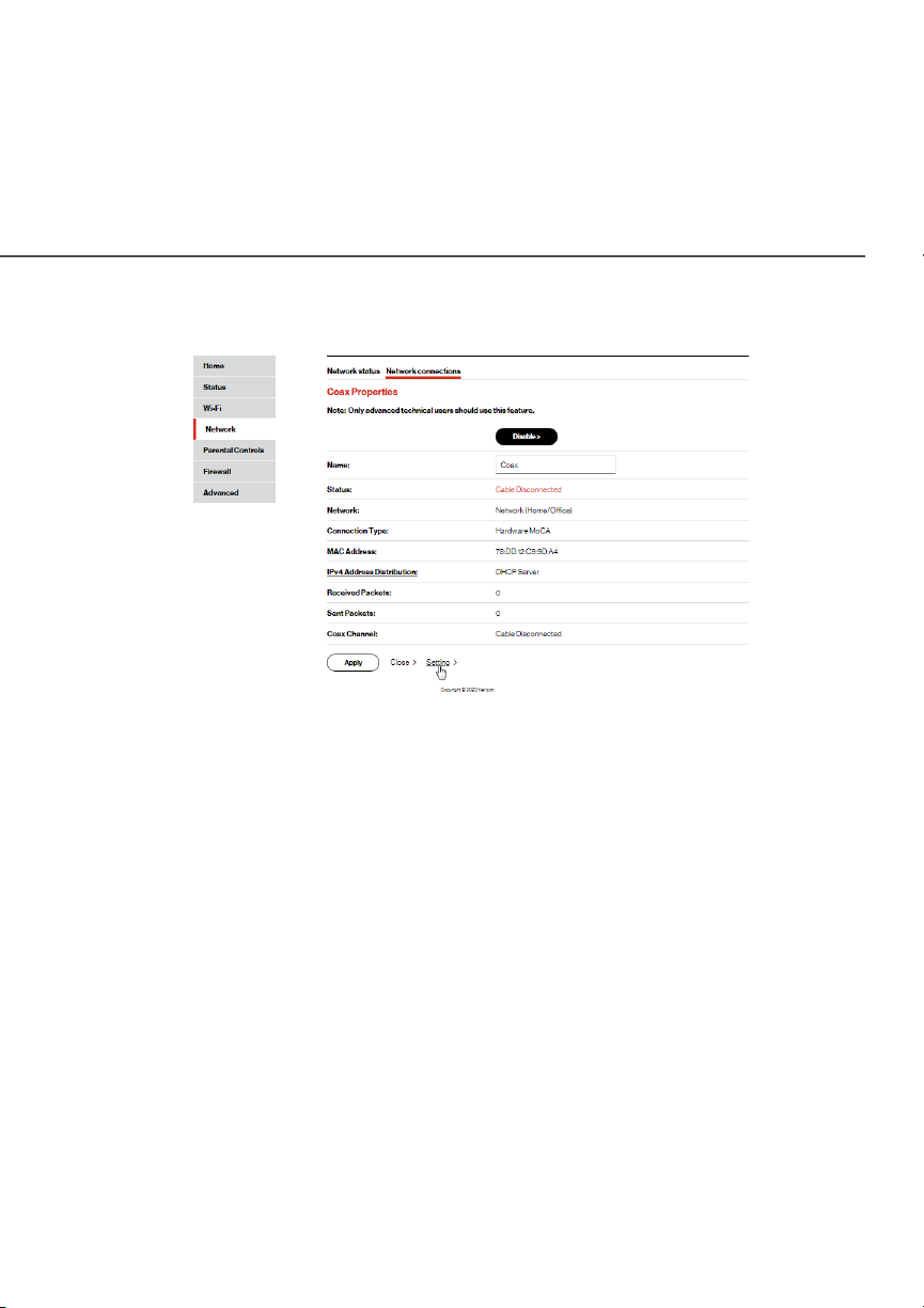
Coax PrCoax Propertiesoperties
2. To rename the network connection, enter the new name in
the NameName field.
74
3. Click ApplyApply to save changes.
5.4a/ CONFIGURING THE ETHERNET/COAX CONNECTION
To configure the connection:
1. In the BrBroadband Connection (Eoadband Connection (Ethernethernet/t/CoaxCoax) Pr) Propertiesoperties
page, click SeSetttingstings. The configuration page displays.
verizon.com/business/products/fios-internet | ©2020 Verizon. All Rights Reserved
Page 75

BROADBAND CONNECTION
(ETHERNET/COAX)
2. Configure the following settings, as needed.
GENERAL
Verify the following information:
• StaStatustus - displays the connection status of the network.
• NeNettwworkork – displays the type of network connection.
• Connection TConnection Typeype - displays the type of connection
interface.
Page 76

• PhPhyysicsical Aal Addrddressess - displays the physical address of the
network card used for the network.
• MTUMTU - specifies the largest packet size permitted for
internet transmissions:
– AAututomaomatictic: sets the MTU (Maximum Transmission Unit
– AAututomaomatic btic by DHCPy DHCP: sets the MTU according to the
– ManualManual: allows you to manually set the MTU.
COAX LINK
• PrivPrivacy - acy - to set PrivPrivacyacy, select the EnabledEnabled check box.
This causes all devices connected to the coaxial cable to
use the same password. This is recommended. To set the
password, enter the Coax Link password in the PPassasswworordd
field.
at 1500).
DHCP connection.
/ USING NETWORK
CONNECTIONS
76
• To enable or disable the Coax link, click DisDisableable or EnableEnable.
• To view the devices connected using the coaxial cable,
click the Go tGo to Wo WAN Coax StaAN Coax Statustus link.
• In the InIntterneernet Prt Proottocolocol section, specify one of the
following:
– No IPNo IPv4 Av4 Addrddressess: the connection has no IP address.
This is useful if the connection operates under a
bridge.
verizon.com/business/products/fios-internet | ©2020 Verizon. All Rights Reserved
Page 77

BROADBAND CONNECTION
(ETHERNET/COAX)
– ObObtain an IPtain an IPv4 Av4 Addrddress Aess Aututomaomaticticallyally: the network
connection is required by Verizon to obtain an IP
address automatically. The server assigning the IP
address also assigns a subnet mask address, which
can be overridden by entering another subnet mask
address.
– UsUse the Fe the Folloollowing IP Awing IP Addrddressess: the network
connection uses a permanent or static IP addrIP addressess
and SubneSubnet Maskt Mask address, provided by Verizon or
experienced network technician.
• To override the subnet mask, select the OvOverride Subneerride Subnet t
MaskMask check box, then enter the new subnet mask.
• Click RReleaseleasee/RReneeneww in the DHCP LDHCP Leaseasee field to drop/
get an IP address from the DHCP server.
• In the ExpirExpires In es In field, enter the amount of time a network
device is allowed to connect to the Fios Router with its
currently issued dynamic IP address.
• IPIPv4 DNS - v4 DNS - selects ObObtain IPtain IPv4 DNS Av4 DNS Addrddress ess
DynamicDynamicallyally for using Dynamic DNS. Each time the public
IP address changes, the DNS database is automatically
updated with the new IPv4 address. In this way, even
though the IP address changes often, the domain name
remains constant and accessible.
• InIntterneernet Connection Firt Connection Fireewwall - all - allows you to enable or
disable the firewall configuration on this interface.
3. Click ApplyApply to save changes.
Page 78

06 /
SETTING PARENTAL CONTROLS
6.0 Activating Parental Controls
6.1 Rule Summary
Page 79

/ SETTING
PARENTAL CONTROLS
The abundance of harmful information
on the internet poses a serious
challenge for employers and parents
alike as they ask “How can I regulate
what my employee or child does on the
internet?”
With that question in mind, your
Fios Router’s Parental Controls were
79
designed to allow control of internet
access on all locally networked devices.
verizon.com/fios | ©2020 Verizon. All Rights Reserved
Page 80

ACTIVATING PARENTAL CONTROLS
./ ACTIVATING PARENTAL CONTROLS
You can create a basic access policy for any computer or device
on your Fios Router network. Parental controls limit internet access
to specific websites based on a schedule that you create.
Access can be limited on specific websites or keywords embedded
in a website. For example, you can block access to the ‘www.
anysite.com’ as well as block any website that has the word ‘any’ in
its site name.
To limit computer access:
1. Select PPararenental Contal Contrtrolsols.
2. In Step 1 (optional), select the computers or device where
you are limiting access in the Primary NePrimary Nettwwork & Guesork & Guest t
NeNettwwork Deork Device Lisvice Listt box, then click AdAddd. The devices
display in the
SelectSelected Deed Devicesvices section.
3. To remove a device from the SelectSelected Deed Devicesvices list box,
select the device, then click
the Primary NePrimary Nettwwork & Guesork & Guest Net Nettwwork Deork Device Lisvice Listt list box.
4. In Step 2, click one of the following options in the
AAccess Byccess By section:
• Block the fBlock the folloollowing Wwing Websitebsites and Embedded Kes and Embedded Keeyywworords ds
within a URLwithin a URL – blocks the specified websites and
websites with names containing the specified keyword.
•
AlloAllow the fw the folloollowing Wwing Websitebsites and Embedded Kes and Embedded Keeyywworords ds
within a URLwithin a URL – allows the specified websites and
websites with names containing the specified keyword.
RReemmoveove. The device displays in
Limit Limit
Page 81

/ SETTING
PARENTAL CONTROLS
81
• Block ALL InBlock ALL Intterneernet At Accessccess – blocks the access to all
internet websites.
5. Enter the name of the WWebsitebsitee or Embedded kEmbedded keeyywworord within d within
a URLa URL, then click AdAddd.
verizon.com/fios | ©2020 Verizon. All Rights Reserved
Page 82

RULE SUMMARY
6. To remove a website or keyword, select the word, then click
RReemmoveove.
7. Create a schedule by selecting the days of the week when
the rule will be active or inactive.
8. Set the time when the rule will be active or inactive, then
specify the start time and end time.
9. Create a rule name and description.
10. Click ApplyApply to save changes.
NEW! The VVerizerizon My Fioson My Fios app provides robust security to protect
your home and business networks. Click the Click herClick heree link to
download the My Fios app for using the My Fios app on the iOS or
Android OS.
. / RULE SUMMARY
You can view the rules created for your Fios Router.
To view the rule summary, select Rule SummaryRule Summary. The Rule
Summary page opens with the rule name, description, and
computer or device displayed.
You can enable, view, edit, or delete the rule; refer to Scheduler
Rules for additional setting details.
Page 83

07 /
CONFIGURING SECURITY SETTINGS
7.0 Firewall
7.1 Access Control
7. 2 Port Forwarding
7.3 Port Triggering
7.4 DMZ Host
7.5 Static NAT
7.6 IPv6 Pinholes
Page 84

/ CONFIGURING
SECURITY SETTINGS
84
Your Fios Router’s security suite
includes comprehensive and robust
security services, such as stateful
packet inspection, firewall security, user
authentication protocols, and password
protection mechanisms.
These and other features help protect
your computers from security threats on
the internet.
verizon.com/fios | ©2020 Verizon. All Rights Reserved
Page 85

FIREWALL
This chapter covers the following security features:
• Firewall - select the security level for the firewall.
• Access Control - restrict access from the local network to the
internet.
• Port Forwarding - enable access from the internet to specified
services provided by computers on the local network.
• Port Triggering - define port triggering entries to dynamically
open the firewall for some protocols or ports.
• DMZ Host - allows a single device on your primary network to
be fully exposed to the internet for special purposes such as
internet gaming.
• Static NAT - allow multiple static NAT IP addresses to be
designated to devices on the network.
• IPv6 Pinhole - provide access tunnel to a service on a host for a
particular application.
• Security Log - view and configure the security log.
. / FIREWALL
The firewall is the cornerstone of the security suite for your
Fios Router. It has been exclusively tailored to the needs of the
residential or oce user and is pre-configured to provide optimum
security.
The firewall provides both the security and flexibility that home
and oce users seek. It provides a managed, professional level
of network security while enabling the safe use of interactive
applications, such as internet gaming and video conferencing.
Page 86

/ CONFIGURING
SECURITY SETTINGS
86
Additional features, including surfing restrictions and access
control, can also be configured locally through the user interface or
remotely by a service provider.
The firewall regulates the flow of data between the local network
and the internet. Both incoming and outgoing data are inspected,
then either accepted and allowed to pass through your Fios Router
or rejected and barred from passing through your Fios Router,
according to a flexible and configurable set of rules. These rules
are designed to prevent unwanted intrusions from the outside, while
allowing local network users access to internet services.
The firewall rules specify the type of services on the internet that
are accessible from the local network and types of services in the
local network that are accessible from the internet.
Each request for a service that the firewall receives is checked
against the firewall rules to determine whether the request should
be allowed to pass through the firewall. If the request is permitted to
pass, all subsequent data associated with this request or session is
also allowed to pass, regardless of its direction.
For example, when accessing a website on the internet, a request
is sent to the internet for this site. When the request reaches your
Fios Router, the firewall identifies the request type and origin, such
as HTTP and a specific computer in the local network. Unless your
Fios Router is configured to block requests of this type from this
computer, the firewall allows this type of request to pass to the
internet.
verizon.com/fios | ©2020 Verizon. All Rights Reserved
Page 87

FIREWALL
When the website is returned from the web server, the firewall
associates the website with this session and allows it to pass;
regardless HTTP access from the internet to the local network is
blocked or permitted. It is the origin of the request, not subsequent
responses to this request, which determines whether a session can
be established.
7.0a/ SETTING FIREWALL CONFIGURATION
You can select a maximum, typical, or minimum security level to
block, limit, or permit all trac. The following table shows request
access for each security level.
Security Level
Internet Requests
Incoming Trac
Local Network Requests
Outgoing Trac
Maximum Blocked Limited
Typical Blocked Unrestricted
Minimum Unrestricted Unrestricted
The request access is defined as:
• Blocked trac - no access allowed, except as configured in
Port Forwarding and Remote Access
• Limited - permits only commonly used services, such as email
and web browsing
• Unrestricted - permits full access of incoming trac from the
internet and allows all outgoing trac, except as configured in
Access Control
Page 88

/ CONFIGURING
SECURITY SETTINGS
7.0b/ SPECIFYING GENERAL SETTINGS FOR IPV4 OR IPV6
To set your firewall configuration:
1. From the Firewall GenerGeneralal settings page, click on desired
IPIPv4 sv4 seetttings/IPtings/IPv6 sv6 seetttingstings option to configure IPv4/IPv6
security.
88
2. Select a security level by clicking one of the radio buttons.
Using the Minimum SecurityMinimum Security setting may expose the local
network to significant security risks, and should only be used
for short periods of time to allow temporary network access.
3. Click ApplyApply to save changes.
verizon.com/fios | ©2020 Verizon. All Rights Reserved
Page 89

ACCESS CONTROL
. / ACCESS CONTROL
You can block individual computers on your local network from
accessing specific services on the internet. For example, you
could block one computer from accessing the internet, then block
a second computer from transferring files using FTP as well as
prohibit the computer from receiving incoming email.
Access control incorporates a list of preset services, such as
applications and common port settings.
7.1a/ ALLOW OR RESTRICT SERVICES
To allow or restrict services:
1. From the Firewall page, select AAccess Conccess Contrtrolol. The Access
Control page opens with the Allows and Blocked sections
displayed. The Allowed section only displays when the
firewall is set to maximum security.
2. To block a service, click AdAddd. The AAdd Add Access Conccess Contrtrol Ruleol Rule
page displays.
Page 90

/ CONFIGURING
SECURITY SETTINGS
3. To apply the rule to:
• Networked Computer/Device - select AAnyny.
• Specific devices only - select UsUser Deer Definedfined.
4. In the Protocol field, select the internet protocol to be
allowed or blocked. If the service is not included in the list,
select UsUser Deer Definedfined. The EEdit Servicedit Service page displays. Define
the service, then click OKOK. The service is automatically
added to the AAdd Add Access Conccess Contrtrol Ruleol Rule section.
90
5. Specify when the rule is active as AAllwwaysays or UsUser Deer Definedfined.
6. Then click AAdd rule sdd rule schedulechedule to specify the days of the week
when the rule will be active.
verizon.com/fios | ©2020 Verizon. All Rights Reserved
Page 91

ACCESS CONTROL
7. Click NeNew Hours Range Enw Hours Range Entry try and set the start time and
end time when the rule will be active.
8. Click ApplyApply to save changes.
9. Click ApplyApply again to save all changes.
10. The Access Control page displays a summary of the new
access control rule.
7.1b/ DISABLE ACCESS CONTROL
You can disable an access control and enable access to the
service without removing the service from the Access Control
table. This can make the service available temporarily and allow
you to easily reinstate the restriction later.
Page 92

/ CONFIGURING
SECURITY SETTINGS
• To disable an access control, clear the check box next to the
service name.
• To reinstate the restriction, select the check box next to the
service name.
• To remove an access restriction, select the service and click
RReemmoveove. The service is removed from the Access Control table.
. / PORT FORWARDING
You can activate port forwarding to expose the network to the
internet in a limited and controlled manner. For example, enabling
applications, such as gaming and voice, to work from the local
network as well as allowing internet access to servers within the
local network.
92
To create port forwarding rules:
1. From the FirFireewwallall page, select PPort Fort Forworwarardingding. The PPort ort
FForworwarardingding page opens with the current rules displayed.
verizon.com/fios | ©2020 Verizon. All Rights Reserved
Page 93

PORT FORWARDING
2. To create a new rule, select the IP address in the Select IP Select IP
frfrom menuom menu drop down.
3. Select the application in the ApplicApplicaation Ttion To Fo Forworwarardd drop
down.
4. Click AdAddd. The rule displays in the Applied RulesApplied Rules section.
5. Click ApplyApply to save changes.
7.2a/ ADVANCED PORT FORWARDING RULES
You can configure advanced port forwarding rules.
To configure the rules:
1. In the PPort Fort Forworwarardingding page, select AAdvdvancedanced.
2. If needed, to select a port to forward communication to,
select an option in the CusCusttom Pom Portsorts drop down.
Page 94

/ CONFIGURING
SECURITY SETTINGS
3. If a single port or range of ports is selected, text boxes
display. Select the PrProottocolocol and the port numbers.
4. To schedule the rule, select either AAllwwaysays or UsUser Deer Definedfined in
the ScheduleSchedule list box.
5. Click AdAddd. The rule displays in the Applied RulesApplied Rules section.
6. Click ApplyApply to save changes.
. / PORT TRIGGERING
Port triggering can be described as dynamic port forwarding. By
setting port triggering rules, inbound trac arrives at a specific
network host using ports that are dierent than those used for
outbound trac. The outbound trac triggers the ports where the
inbound trac is directed.
94
For example, a gaming server is accessed using UDP protocol on
port 2222. The gaming server then responds by connecting the
user using UDP on port 3333, when a gaming session is initiated.
In this case, port triggering must be used since it conflicts with the
following default firewall settings:
• Firewall blocks inbound trac by default.
• Server replies to your Fios Router IP, and the connection is not
sent back to the host since it is not part of a session.
verizon.com/fios | ©2020 Verizon. All Rights Reserved
Page 95

PORT TRIGGERING
To resolve the conflict, a port triggering entry must be defined,
which allows inbound trac on UDP port 3333 only after a network
host generated trac to UDP port 2222. This results in your
Fios Router accepting the inbound trac from the gaming server
and sending it back to the network host which originated the
outgoing trac to UDP port 2222.
To configure port triggering:
1. Select Port Triggering.
2. To add a service as an active protocol, click AdAddd. The EEdit dit
PPort Tort Triggering Ruleriggering Rule page displays.
3. Enter the service name then configure its inbound and
outbound trigger ports. Click AdAddd to save changes.
Page 96
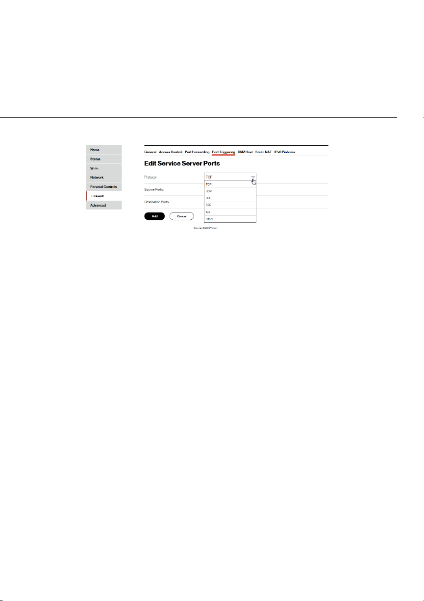
/ CONFIGURING
SECURITY SETTINGS
96
4. Click ApplyApply to save all changes.
. / DMZ HOST
DMZ Host allows a single device on your primary network to be fully
exposed to the internet for special purposes like internet gaming.
Warning: Enabling DMZ Host is a security risk. When a device on
your network is a DMZ Host, it is directly exposed to the internet
and loses much of the protection of the firewall. If it is compromised,
it can also be used to attack other devices on your primary network.
Follow these steps to designate a device on your primary network
as a DMZ Host:
1. From the FirFireewwallall page, select DMZ HosDMZ Hostt.
2. Select EnableEnable for the DMZ Host.
3. Enter the IP address of the device you want to designate as
the DMZ Host.
4. Click ApplyApply.
verizon.com/fios | ©2020 Verizon. All Rights Reserved
Page 97

STATIC NAT
. / STATIC NAT
Static NAT allows devices located behind a firewall that is
configured with private IP addresses to appear to have public IP
addresses to the internet. This allows an internal host, such as a
web server, to have an unregistered (private) IP address and still be
accessible over the internet.
To configure static NAT:
1. Select StaStatic NAtic NATT.
2. To create a static NAT, click AdAddd. The AAdd NAdd NATT/NAPT Rule/NAPT Rule
page displays.
Page 98

/ CONFIGURING
SECURITY SETTINGS
98
3. Select a source address in the SpecifSpecify Ay Addrddressess field or enter
an IP address in the text box.
4. Enter the Public IP APublic IP Addrddressess.
5. If using port forwarding, select the Enable PEnable Port Fort Forworwararding ding
ffor Staor Static NAtic NATT check box.
6. Click ApplyApply to save changes.
7. Repeat these steps to add additional static IP addresses.
verizon.com/fios | ©2020 Verizon. All Rights Reserved
Page 99

IPV PINHOLES
. / IPV PINHOLES
The IPv6 Pinhole feature of the Fios Router allows an application to
send incoming packets for a certain port number to the destination
computer by setting up the rule of authorization.
You can view the Pinhole rules created for your Fios Router. To
view the rule summary, select IPIPv6 Pinholev6 Pinhole. The screen displays
opened pinhole port and its status. It shows the IP addresses of
remote device and connected device on your network.
You can enable, view, edit, or delete the rules as shown on the
above screen.
Page 100

08 /
CONFIGURING ADVANCED SETTINGS
8.0 Using Advanced Settings
8.1 Utilities
8.2 Network Settings
8.3 Date And Time
8.4 DNS Settings
8.5 Monitoring
8.6 System Settings
 Loading...