


VH7200 Humidistat Series
For Humidification & Dehumidification Control
For Commercial HVAC Applications
(Issue Date September 29, 2008 – 028-0208 R4)
Product overview |
|
The VH7200 humidity controller family is specifically designed for control of |
|
humidification and dehumidification equipment such as steam header direct |
|
injection, desiccant wheel, or stand alone humidification / dehumidification |
|
equipment. The product features a complete embedded humidity control |
|
solution with an intuitive backlit LCD display that walks the installer through the |
|
configuration steps, making the process extremely simple. Accurate relative |
|
humidity control is achieved due to the product’s unique PI time proportional |
|
control algorithm, which virtually eliminates humidity offset associated with |
|
traditional, differential-based humidity controllers. |
|
All models contain a binary input, which can be set by the user to monitor an |
|
electrode humidifier canister service status or may be used as a general |
|
purpose service indicator. Models are available which contain more advanced |
|
features such as discharge humidity proportional high limit, and indoor humidity |
|
setpoint reset based upon outdoor air temperature to conserve energy and |
|
eliminate condensation on windows and structure. |
Fig.1 VH7200 series humidistats |
|
The additional following documents are available at: www.viconics.com
•Information on the BACnet models (VH72xxX1000B), is available on document ITG-VH7200-BAC-Exx
Models available
|
|
Application |
|
|
Model Number |
|
|
|
|
|
Dehumidification |
|
|
|
|
|
|
|
|
|
|
|
|
Output |
|
|
|
||
|
|
|
|
|
|
|
|
|
|
|
|
|
|
|
|
|
|
|
|
|
|
|
|
|
|||||
|
|
Model with Outdoor reset & Proportional High Limit |
|
VH7270K1000 (X) |
|
|
|
|
|
On-Off 24 Vac |
|
|
|
|
|
|
|
|
|
|
|
|
|
|
|
||||
|
|
|
|
|
|
|
|
|
|
|
|
|
|
|
|
|
|
|
|
|
|
|
|
|
|
|
|||
|
|
Model with Outdoor reset & Proportional High Limit |
|
VH7270F1000 (X) |
|
|
|
|
|
On-Off 24 Vac |
|
|
|
|
|
|
|
|
|||||||||||
|
|
|
|
|
|
|
|
|
|
|
|
|||
|
|
Models with outdoor reset only |
|
VH7200A1000 (X) |
|
|
|
|
|
On-Off 24 Vac |
|
|
|
|
|
|
|
|
|||||||||||
|
|
|
|
|
|
|
|
|
|
|
|
|
|
|
|
|
|
|
|
|
|
|
|
|
|
|
|
|
|
|
|
* NEW * Duct Mount Model with Outdoor reset & |
|
VH7270D1000 (X) |
|
|
|
|
|
On-Off 24 Vac |
|
|
|
|
|
|
|
|
|
|
|
|
|
|
|
||||
|
|
Proportional High Limit |
|
|
|
|
|
|
|
|
|
|||
|
|
|
|
|
|
|
|
|
|
|
|
|
|
|
|
|
|
|
|
|
|
|
|
||||||
(X) model number represents available communication options: X=none for Stand-alone and X=B for BACnet MS-TP. |
||||||||||||||
Features and benefits |
|
|
|
|
|
|
|
|
|
|
|
|
||
|
|
|
|
|
|
|
|
|
|
|||||
|
|
Features |
|
|
Benefits |
|
|
|
|
|||||
|
|
• Embedded humidification and dehumidification |
|
|
Simplifies installation and reduce installation |
|
||||||||
|
|
sequences |
|
|
costs |
|
|
|
|
|||||
|
|
• Embedded internal RH sensor |
|
|
Eliminates components |
|
|
|
|
|||||
|
|
• Proportional high limit override |
|
|
Prevents costly damage due supply humidity |
|
||||||||
|
|
• (VH7270 Models Only) |
|
|
condensation |
|
|
|
|
|||||
|
|
• Humidity setpoint reset based on outdoor |
|
|
Saves energy and prevents window |
|
||||||||
|
|
temperature |
|
|
condensation in colder climates |
|
|
|
|
|||||
|
|
• Sensor failure protection |
|
|
Prevents water damage |
|
|
|
|
|||||
|
|
• PI time proportioning algorithm |
|
|
Increased comfort, accuracy, and energy savings |
|
||||||||
|
|
• Binary input |
|
|
Adds functionality (Trigger service alarms ) |
|
||||||||
|
|
• Unique configuration menu routine |
|
|
Minimizes parameter tampering |
|
|
|
|
|||||
|
|
• Lockable keypad |
|
|
Tamper proof, no need for humidistat guards |
|
||||||||
|
|
• EEPROM memory |
|
|
No loss configuration parameters |
|
||||||||
|
|
• Optional remote humidity sensors |
|
|
Increase flexibility and functionality |
|
||||||||
|
028-0208 R4_LIT-VH72x0-E14.doc |
|
|
|
|
|
www.viconics.com / sales@viconics.com |
|||||||
2
Features overview
•Internal RH sensor and optional remote RH input with embedded humidification and dehumidification sequence of operation.
•Humidity set point reset based upon outdoor temperature sensing for added flexibility.
•Proportional high limit input to prevent over-humidification due to supply humidity condensation.
•Lockable keypads for tamper proofing. No need for extra humidistat guard.
•Programmable binary input for added flexibility. The input can be programmed as the following:
-None: No function will be associated with the input
-Service: a backlit flashing Service alarm will be displayed on the humidistat LCD screen when the input is energized. It can be tied in to the AC unit control card, which provides an alarm in case of malfunction.
-Canister: a backlit flashing Canister alarm will be displayed on the humidistat LCD screen when the input is energized. It can be tied to a Dry contact output supplied by others.
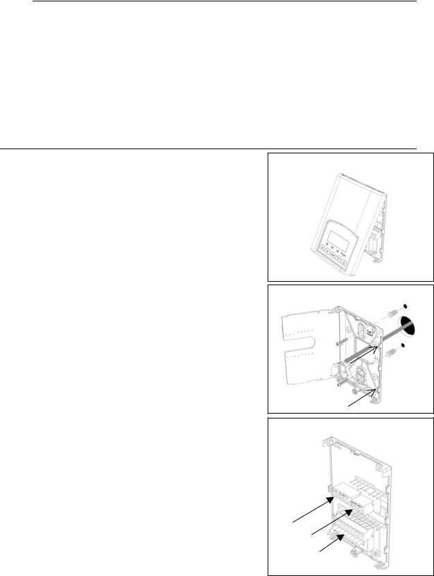
Installation
•Remove security screw on the bottom of humidistat cover.
•Open up by pulling on the bottom side of humidistat.
•Remove Assembly and remove wiring terminals from sticker.
(Fig. 2)
A) Location:
1- Should not be installed on an outside wall. 2- Must be installed away from any heat source.
3- Should not be installed near an air discharge grill. 4- Should not be affected by direct sun radiation.
5- Nothing must restrain vertical air circulation to the humidistat.
B) Installation:
1- Swing open the humidistat PCB to the left by pressing the PCB locking tabs. (Fig. 3)
2- Pull out cables 6” out of the wall.
3- Wall surface must be flat and clean.
4- Insert cable in the central hole of the base.
5- Align the base and mark the location of the two mounting holes on the wall. Install proper side of base up.
6- Install anchors in the wall.
7- Insert screws in mounting holes on each side of the base.
(Fig. 3)
8- Gently swing back the circuit board on the base and push on it until the tabs lock it.
10Strip each wire 1/4 inch.
11Insert each wire according to wiring diagram. 13Gently push back into hole excess wring (Fig. 4)
14- Re-Install wiring terminals in correct location. (Fig. 4) 15Reinstall the cover (top side first) and gently push back
extra wire length into the hole in the wall. 16Install security screw.
For VH7270D1000 duct-mount model only:
1- Make 1” diameter hole in duct wall
2- Insert the duct sensor and fix the electrical box to the duct wall in the vertical position (respect airflow direction).
3- Install the humidistat to the electrical box using the supplied screws (2).
4- Follow steps 1-16 above.
Note: For dimensions please see page 14
Fig.2
Fig.3
Fig.4

3
Wiring
Terminal identification & screw terminal arrangement
|
Part Number |
|
VH7270K |
|
VH7270D/F |
|
|
|
VH7200A |
||||
|
|
|
|
|
|
Top left |
terminal block |
|
|
|
|
||
1 |
|
|
Not used |
|
|
Not used |
|
|
|
Not used |
|||
2 |
HUM |
|
|
|
|
X |
|
|
Not used |
|
|
|
X |
|
|
|
|
|
|
|
|||||||
3 |
HUM |
|
|
|
|
X |
|
|
Not used |
|
|
|
X |
|
|
|
|
|
|
|
|||||||
4 |
R |
|
|
|
|
X |
|
|
X |
|
|
|
X |
5 |
C |
|
|
|
|
X |
|
|
X |
|
|
|
X |
|
|
|
|
|
|
Top right |
terminal block |
|
|
|
|
||
6 |
DEH |
|
|
|
|
X |
|
|
X |
|
|
|
X |
|
|
|
|
|
|
|
|
|
|||||
7 |
DEH |
|
|
|
|
X |
|
|
X |
|
|
|
X |
|
|
|
|
|
|
|
|
|
|||||
8 |
|
|
Not used |
|
|
Not used |
|
|
|
Not used |
|||
|
|
|
|
|
|
Bottom |
terminal block |
|
|
|
|
||
9 |
|
|
Not used |
|
|
Not used |
|
|
|
Not used |
|||
10 |
|
|
Not used |
|
|
Not used |
|
|
|
Not used |
|||
11 |
HUM 0-10 |
|
|
|
|
X |
|
|
X |
|
|
|
Not used |
12 |
DI1 |
|
|
|
|
X |
|
|
X |
|
|
|
X |
13 |
HS |
|
|
|
|
X |
|
|
X |
|
|
|
X |
14 |
SCOM |
|
|
|
|
X |
|
|
X |
|
|
|
X |
15 |
OS |
|
|
|
|
X |
|
|
X |
|
|
|
X |
16 |
HL |
|
|
|
|
X |
|
|
X |
|
|
|
Not used |
Fig.5 : VH7200’s wiring terminals
Wiring notes:
Note 1:
Reference of the analog 0-10 Vdc control signal is the common of the power supply of the humidistat. (terminal C)
Note 2:
Electromechanical dry contact is to be used with the binary input. Electronic triacs cannot be used as mean of switching for the input. The switched leg to the input for the input to activate is terminal Scom
Note 3:
The transformer of the unit provides power to the humidistat and any additional loads wired to the humidistat.
Note 4:
Both the remote humidity sensors ( HS & HL terminals ) use 0 to 10 Vdc type humidity sensors.
Detailed wiring diagram for model VH7270K1000 |
|
|
|
|
|
|
|
|
|||||
|
|
|
|
|
|
HumidificationOutput : |
|
|
|
|
|
||
|
|
|
|
|
|
( On/Off ) or ( 0-10 Vdc ) |
|
|
|
|
|
||
|
|
|
|
|
|
Refer to parameter: |
|
|
|
|
S.A. |
||
|
|
|
|
|
|
|
"SeqOpera" |
|
|
|
|
|
|
|
|
|
|
|
|
|
FLOW |
(0-10 Vdc) |
|
FLOW |
|
|
|
VH2030D1000 |
VH7270K1000 |
|
(On/Off) HUMIDIFIER |
SWITCH |
|
SWITCH |
VH2030D1000 |
||||||
|
|
|
|
HUMIDIFIER |
|
HUMIDITY TRANSMITTER |
|||||||
OPTIONAL |
HUMIDITY CONTROLLER |
H |
H |
|
|
|
|
( OPTIONAL HIGH LIMIT ) |
|||||
DUCT |
|
0-10 24V |
Com |
X |
|||||||||
MOUNTED |
|
|
|
|
|
|
|
X |
|
|
|||
|
|
|
|
Dry contact |
|
|
|
|
|
COM. 24 Vac |
0-10 Vdc |
||
HUMIDITY |
|
|
|
|
|
|
|
|
|
||||
TRANSMITTER |
|
|
|
|
|
|
|
|
|
|
BLACK |
RED |
ORANGE |
VH2030W1000 |
|
|
|
|
|
|
|
|
|
|
|||
|
|
|
|
|
|
|
|
|
|
|
|
|
|
OPTIONAL |
|
|
|
|
|
Dehumidification |
|
|
|
|
|
|
|
WALL |
|
|
|
|
|
|
|
|
|
|
|
||
|
|
|
|
Dry contact |
and/or |
|
|
|
|
|
|
||
MOUNTED |
|
|
|
|
|
|
|
|
|
|
|
|
|
|
|
|
|
|
air exchanger |
|
|
|
|
|
|
||
HUMIDITY |
HUMHUM R |
C |
|
|
|
|
|
|
|
|
|
||
DEH DEH |
|
|
|
|
|
|
|
|
|
|
|||
TRANSMITTER |
|
|
|
|
|
|
|
|
|
|
|||
|
|
|
|
|
|
|
|
|
|
|
|
||
Note: |
|
|
|
|
|
|
|
|
|
|
|
|
|
When a remote |
or |
|
|
|
|
|
|
|
|
|
|
|
|
humidity |
|
|
|
|
|
|
|
|
|
|
|
|
|
transmitter |
HUM |
|
|
|
|
|
|
|
|
|
|
|
|
is connected to |
0-10 DI1 |
HS Scom OS |
HL |
|
|
|
|
|
|
|
|
|
|
the VH7200, |
|
|
|
|
|
|
|
|
|
|
|
|
|
it's internal |
|
|
|
|
|
|
|
|
|
|
|
|
|
humidity |
|
|
|
|
|
|
|
|
|
|
Binary Input "Di1" Set |
|
|
sensor is |
|
|
|
|
S2020E1000 or S2000D1000 |
|
|
|
for "SERVICE" alarm |
|
|||
automatically |
|
|
|
|
|
OPTIONAL OUTDOOR |
|
|
|
|
|
|
|
|
|
|
|
|
TEMPERATURE SENSOR |
|
|
|
|
|
|
||
disabled. |
|
|
|
|
|
|
|
|
|
|
|
||
|
|
|
|
|
|
|
|
|
|
|
|
|
|
Fig.6 : VH7270F1000 wiring diagram

4
Specific wiring diagrams for all models VH7200A1000, VH7270F1000, VH7270K1000
24 Vac Hot
On/Off Humidification
On/Off Humidification
24 Vac Com.
On/Off Dehumidification
On/Off Dehumidification
HUM HUM |
R |
C |
DEH DEH |
|
|
|
VH7270K1000 Universal
Analog 0-10 Vdc Humidification Digital input, dry contact to "Scom"
Remote humidity sensor (opt.)
HUM |
DI1 HS |
Scom |
OS |
HL |
|
0-10 |
|||||
|
Supply Humidity High Limit Sensor (opt.)
Outside air temperature sensor (opt.)
Sensor(s) and BI input common
24 Vac Com.
24 Vac Hot
VH7270F1000 Analog
VH7270D1000 Analog
Analog 0-10 Vdc Humidification Digital input, dry contact to "Scom"
Remote humidity sensor (opt.)
On/Off Dehumidification
On/Off Dehumidification
R |
C |
DEH DEH |
|
|
HUM |
DI1 HS |
Scom |
OS |
HL |
|
0-10 |
|||||
|
Supply Humidity High Limit Sensor (opt.)
Outside air temperature sensor (opt.)
Sensor(s) and BI input common
24 Vac Hot
On/Off Humidification
On/Off Humidification
24 Vac Com.
On/Off Dehumidification
On/Off Dehumidification
HUM HUM |
R |
C |
DEH DEH |
|
|
|
VH7200A1000 On/Off

 DI1
DI1  HS
HS  Scom
Scom OS
OS 

Digital input, dry contact to "Scom"  Optional remote humidity sensor
 Outside air temperature sensor (opt.) Sensor(s) and BI input common

5
Remote humidity sensor accessories
Model number
VH2020W1000
VH2020D10000
S2000D1000
S2020E1000
S1010E1000
Wall mounted humidity transmitter 2% R.H. Duct mounted humidity sensor 2% R.H. Duct mounted outside air temperature sensor
Outside air temperature sensor in a NEMA 4 enclosure Outside air temperature sensor, capsule type ( ¼” dia., 1” long )
VH2020W1000, remote wall mounted room humidity sensor.
(see Fig.8) (wiring diagram next page)
VH2020D1000, remote duct mounted humidity sensor c/w junction box.
(see Fig.9) (wiring diagram next page)
This sensor can be used for:
•Remote return air humidity sensing with the sensor mounted on the return air duct.
•Supply air humidity sensor used as a high limit protection.
S2020E1000, commercial style outside air temperature sensor in a NEMA 4 enclosure. (see Fig.10) (wiring diagram next page)
S1010E1000, residential style outside air temperature sensor, capsule type. (see Fig.11) (wiring diagram next page)
•These sensors are used for the humidity setpoint reset function based on outdoor temperature.
INSTALLATION NOTICE !
 • If replacing an old humidistat, label the wires
before removal of the old humidistat.
 • Electronic controls are static sensitive devices. Discharge yourself properly before manipulation and installing the humidistat.
•Short circuit or wrong wiring may permanently damage the humidistat or the equipment.
•Anti-short cycling can be set to 0 minutes for equipment that posses their own anti cycling timer. Do not use that value unless the equipment is equipped with such internal timer. Failure to do so can damage the equipment.
•All VH7200 series humidistat are to be used only as operating controls. Whenever a control failure could lead to personal injury and/or loss of property, it becomes the responsibility of the user to add safety devices and/or alarm system to protect against such catastrophic failures.
Fig.9– VH2020W1000
Fig.10 – VH2020D1000 / S2000D1000
Fig.11 – S2020E1000
Fig.12 – S1010E1000
 Loading...