


FLOW SENSORS
TM
INSTALLATION GUIDE
FSRxxxx SERIES
Ultrasonic Flow Meter
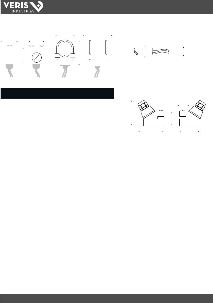
PRODUCT IDENTIFICATION
Monitor: FSR Series
Transducers: FST1, FST2, FST3, FST4, FST5
FSR
Note: Do not cut transducer cables to alter length. This will void the factory warranty. Cables are available in several lengths. Assess the installation location prior to ordering to determine the optimum length. If the wrong length is ordered, contact the factory.
FST1, 2, 3 |
FST4, 5 |
DIMENSIONS
FSR Monitor
Temp Sensors


 DANGER
HAZARD OF ELECTRIC SHOCK, EXPLOSION, OR ARC FLASH
•Followsafeelectricalworkpractices.SeeNFPA70EintheUSA,orapplicablelocalcodes.
•Thisequipmentmustonlybeinstalledandservicedbyqualifiedelectricalpersonnel.
•Read,understandandfollowtheinstructionsbeforeinstallingthisproduct.
•Turno allpowersupplyingequipmentbeforeworkingonorinsidetheequipment.
•Useaproperlyratedvoltagesensingdevicetoconfirmpoweriso . DONOTDEPENDONTHISPRODUCTFORVOLTAGEINDICATION
Failure to follow these instructions will result in death or serious injury.
A quali ed person is one who has skills and knowledge related to the construction and operation of this electrical equipment and the installation, and has received safety training to recognize and avoid the hazards involved. NEC2009 Article 100
No responsibility is assumed by Veris Industries for any consequences arising out of the use of this material.
NOTICE
•Thisproductisnotintendedforlifeorsafetyapplications.
•Donotinstallthisproductinhazardousorclassifiedlocations otherthanthoselistedinSpecifications.
•Readandunderstandtheinstructionsbeforeinstalling thisproduct.
•Turno allpowersupplyingequipmentbeforeworkingonit.
•Theinstallerisresponsibleforconformancetoallapplicablecodes.
No responsibility is assumed by Veris Industries for any consequences arising out of the use of this material.
6.4” |
|
|
4.1” |
||||
(163 mm) |
(105 |
mm) |
|||||
6.0” |
|
|
|
|
|
||
|
|
|
|
||||
(153 mm) |
|
|
|
|
|
|
|
4.3” (110 mm)
0.75”  (19 mm)
 2x 0.5” (13 mm)
1.4” (35 mm)
2.1” (53 mm)
Z205739-0D |
PAGE 1 |
©2013 Veris Industries USA 800.354.8556 or +1.503.598.4564 / support@veris.com |
05131 |
Alta Labs, Enercept, Enspector, Hawkeye, Trustat, Aerospond, Veris, and the Veris ‘V’ logo are trademarks or registered trademarks of Veris Industries, L.L.C. in the USA and/or other countries.
FSRxxxx SERIES
TM
INSTALLATION GUIDE
|
|
|
|
|
|
|
|
|
|
|
|
|
|
FST(1, 2, 3) Transducer |
|
|
|
|
|
|
|
|
|
|
|
|
|
|
|
|
|
|
|
|
|
FST(1, 2, 3) Insert Temperature Sensor |
||||||||||||||||||||||||||||||||||
|
|
|
|
|
|
|
|
|
|
|
|
|
|
|
|
|
|
|
|
|
|
|
|
|
A |
|
|
|
|
|
|
|
|
|
|
|
|
|
C |
|
|
|
|
|
|
Cable Diameter |
|
|
|
|
|
|
|
|
|
|
|
|
|
|
|
|
||||||||
|
|
|
|
|
|
|
|
|
|
|
|
|
|
|
|
|
|
|
|
|
|
|
|
|
|
|
|
|
|
|
|
|
|
|
|
|
|
|
|
|
|
|
|
|
|
|
|
|
|
|
|
|
|
|
|
|
|
|
|
|||||||||||
|
|
|
C |
|
|
|
|
|
|
|
|
|
A |
|
|
|
|
|
|
|
|
|
|
|
|
|
|
|
|
|
|
|
|
|
|
|
|
|
|
|
0.3 “ (7 mm) |
|
|
|
0.5 “ |
|||||||||||||||||||||||||
|
|
|
|
|
|
|
|
|
|
|
|
|
|
|
|
|
|
|
|
|
|
|
|
|
|
|
|
|
|
|
|
|
|
|
|
|
|
|
|
|
|
|
|
|
|
|||||||||||||||||||||||||
|
|
|
|
|
|
|
|
|
|
|
|
|
|
|
|
|
|
|
|
|
|
|
|
|
|
|
|
|
|
|
|
|
|
|
|
|
|
|
|
|
|
|
|
|
|
|||||||||||||||||||||||||
|
|
|
|
|
|
|
|
|
|
|
|
|
|
|
|
|
|
|
|
|
|
|
|
|
|
|
|
|
|
|
|
|
|
|
|
|
|
|
|
|
|
|
|
|
|
|
|
|
|
|
|
|
|
|
|
|
(13 mm) |
|
|
|||||||||||
|
|
|
|
|
|
|
|
|
|
|
|
|
|
|
|
|
|
|
|
|
|
|
|
|
|
|
|
|
|
|
|
|
|
|
|
|
|
|
|
|
|
|
|
|
|
|
|
|
|
|
|
|
|
|
|
|
||||||||||||||
|
|
|
|
|
|
|
|
|
|
|
|
|
|
|
|
|
|
|
|
|
|
|
D |
|
|
|
|
|
|
|
|
|
|
|
|
|
|
|
|
|
|
|
|
|
|
|
|
|
|
|
|
|
|
|
|
|
|
|
|
|
|
|
|
|
0.2 “ |
|||||
|
|
|
|
|
|
|
|
|
|
|
|
|
|
|
|
|
|
|
|
|
|
|
|
|
|
|
|
B |
|
|
|
|
|
|
|
|
|
|
|
|
|
|
|
|
|
|
|
|
|
|
|
|
|
|
|
|
|
|
|
|
|
|||||||||
|
|
|
|
|
|
|
|
|
|
|
|
|
|
|
|
|
|
|
|
|
|
|
|
|
|
|
|
|
|
|
|
|
|
|
|
|
|
|
|
|
|
|
|
|
|
|
|
|
|
|
|
|
|
|
|
|
|
|
|
|
|
|
|
(5 mm) |
||||||
|
|
|
|
|
|
|
|
|
|
|
|
|
|
|
|
|
|
|
|
|
|
|
|
|
|
|
|
|
|
|
|
|
|
|
|
|
|
|
|
|
|
|
|
|
|
|
|
|
|
|
|
|
|
|
|
|
|
|
|
|
|
|
|
|||||||
|
|
|
|
|
|
|
|
|
B |
|
|
D |
|
|
|
|
|
|
|
|
|
|
|
|
|
|
|
|
|
|
|
|
|
|
|
|
|
|
|
|
|
|
|
|
|
|
|
|
|
|
|
|
|
|
|
|
|
|
|
|
|
|
||||||||
|
|
|
|
|
|
|
|
|
|
|
|
|
|
|
|
|
|
|
|
|
|
|
|
|
|
|
|
|
|
|
|
|
|
|
|
|
|
|
|
|
|
|
|
|
|
|
|
|
|
|
|
|
|
|
|
|
|
|
|
|
|
|
|
|
|
|
|
|
|
|
|
|
|
|
|
|
|
|
|
|
|
|
|
|
|
|
|
|
|
|
|
|
|
|
|
|
|
|
|
|
|
|
|
|
|
|
|
|
|
|
|
|
|
|
|
|
|
|
|
|
|
|
|
|
|
|
|
|
|
|
|
|
|
|
|
|
|
|
|
|
|
|
|
|
|
|
|
|
|
|
|
|
|
|
|
|
|
|
|
|
|
|
|
|
|
|
|
|
|
|
|
|
|
|
|
|
|
|
|
|
|
|
|
|
|
|
|
|
|
|
|
|
|
|
|
|
|
|
|
|
|
|
|
|
|
|
|
|
|
|
|
|
|
|
|
|
|
|
|
|
|
|
|
|
|
|
|
|
|
|
|
|
|
|
|
|
|
|
|
|
|
|
|
|
|
|
|
|
|
|
|
|
|
|
|
|
|
|
|
|
|
|
|
|
|
|
|
|
|
|
|
|
|
|
|
|
|
|
|
|
|
|
|
|
|
|
|
|
|
|
|
|
|
|
|
|
|
|
|
|
|
|
|
|
|
|
|
|
|
|
|
U-Bolt Connection |
|
|
|
|
|
|
|
|
|
|
|
|
|
|
|
|
|
|
|
|
|
|
|
|
|
|
|
|
|
|
|
|
|
|
||||||||
|
|
|
|
|
|
|
|
|
|
|
|
|
|
|
|
|
|
|
|
|
|
|
|
|
|
|
|
|
(2” Pipe Only) |
|
|
|
|
|
|
|
|
|
|
|
|
|
|
|
|
|
|
|
|
|
|
|
|
|
|
|
|
|
|
|
|
|
|
|||||||
|
|
|
|
|
|
|
|
|
|
|
|
|
|
|
|
|
|
|
|
|
|
|
|
|
|
|
|
|
|
|
|
FST(4, 5) Transducer |
||||||||||||||||||||||||||||||||||||||
|
|
Pipe |
|
|
Pipe |
|
|
|
A |
|
|
|
B |
|
|
|
|
|
|
C |
|
|
|
D |
|
|
|
|
|
|
|
|||||||||||||||||||||||||||||||||||||||
|
|
Size |
|
Material |
|
|
|
|
|
|
|
|
|
|
|
|
|
|
|
|
|
|
|
|
|
|
|
|
|
|
|
|
|
|
|
|
|
|
|
|
|
|
|
|
|
|
|
|
|
|
|
|
|
|
|
|
0.75” |
|||||||||||||
|
|
|
|
|
|
ANSI |
|
2.46”(63 mm) |
2.36”(60 mm) |
|
|
2.66”(68 mm) |
|
0.840 (22 mm) |
|
|
|
|
|
|
|
|
|
|
|
|
|
|
|
|
|
(19 mm) |
||||||||||||||||||||||||||||||||||||||
|
|
|
|
|
|
|
|
|
|
|
|
|
|
|
|
|
|
|
|
|
|
|||||||||||||||||||||||||||||||||||||||||||||||||
|
|
|
|
|
|
|
|
|
|
|
|
|
|
|
|
|
|
|
|
|
|
|||||||||||||||||||||||||||||||||||||||||||||||||
|
|
|
|
|
|
|
|
|
|
|
|
|
|
|
|
|
|
|
|
|
|
|
|
|
|
|
|
|
|
|
|
|
|
|
|
|
|
|
|
|||||||||||||||||||||||||||||||
|
|
½” |
|
Copper |
|
2.46”(63 mm) |
2.36”(60 mm) |
|
|
3.33”(85 mm) |
|
0.625”(16 mm) |
|
|
|
|
|
|
|
|
|
|
|
|
|
|
|
|
|
|
|
|
|
|
|
|
|
|
|
|||||||||||||||||||||||||||||||
|
|
|
|
|
|
|
|
|
|
|
|
|
|
|
|
|
|
|
|
|
|
|
|
|
|
|
|
|||||||||||||||||||||||||||||||||||||||||||
|
|
2.7” |
|
|
|
|
|
|
|
|
|
|
|
|
|
|
|
|
|
|
|
|
|
|
|
|
||||||||||||||||||||||||||||||||||||||||||||
|
|
|
|
|
|
|
|
|
|
|
|
|
|
|
|
|
|
|
|
|
|
|
|
|
|
|
|
|
|
|
|
|
|
|
|
|
|
|
|
|
|
|
|
|
|
|
|
|
|
|
|
|
|
|
|
|
|
|
|
|
|
|
|
|
|
|
|
|
||
|
|
|
|
|
|
Tubing |
|
2.46”(63 mm) |
2.28”(58 mm) |
|
|
3.33”(85 mm) |
|
0.500”(13 mm) |
(67 mm) |
|
|
|
|
|
|
|
|
|
|
|
|
|
|
|
|
|
|
|
|
|
|
|
|
|||||||||||||||||||||||||||||||
|
|
|
|
|
|
|
|
|
|
|
|
|
|
|
|
|
|
|
|
|
|
|
|
|
|
|
|
|
||||||||||||||||||||||||||||||||||||||||||
|
|
|
|
|
|
|
|
|
|
|
|
|
|
|
1.6” |
|
|
|
|
|||||||||||||||||||||||||||||||||||||||||||||||||||
|
|
|
|
|
|
ANSI |
|
2.46”(63 mm) |
2.57”(66 mm) |
|
|
2.66”(68 mm) |
|
1.050”(27 mm) |
|
|
|
|
|
|
|
|
|
|
|
|
|
|
|
|
|
|||||||||||||||||||||||||||||||||||||||
|
|
|
|
|
|
|
|
|
|
|
|
|
|
|
|
|
|
|
|
|
|
(40 mm) |
|
|
|
|
|
|
|
|||||||||||||||||||||||||||||||||||||||||
|
|
|
|
|
|
|
|
|
|
|
|
|
|
|
|
|
|
|
|
|
|
|
|
|||||||||||||||||||||||||||||||||||||||||||||||
|
¾” |
|
Copper |
|
2.46”(63 mm) |
2.50”(64 mm) |
|
|
3.56”(91 mm) |
|
0.875”(23 mm) |
|
|
|
|
|
|
|
|
|
|
|
|
|
|
|
|
|
|
|
|
|
|
|
2.2” |
|||||||||||||||||||||||||||||||||||
|
|
|
|
|
|
|
|
|
|
|
|
|
|
|
|
|
|
|
|
|
|
|
|
|||||||||||||||||||||||||||||||||||||||||||||||
|
|
|
|
|
|
|
|
|
|
|
|
|
|
|
|
|
|
|
|
|
|
|
|
|||||||||||||||||||||||||||||||||||||||||||||||
|
|
|
|
|
|
|
|
2.9” |
|
|
|
|
|
|
|
|
|
|
|
|
||||||||||||||||||||||||||||||||||||||||||||||||||
|
|
|
|
|
|
Tubing |
|
2.46”(63 mm) |
2.50”(64 mm) |
|
|
3.56”(91 mm) |
|
0.750”(19 mm) |
|
|
|
|
|
|
|
|
|
|
|
|
|
|
|
|
|
|
|
|||||||||||||||||||||||||||||||||||||
|
|
|
|
|
|
|
|
|
|
|
|
|
|
|
|
|
|
|
|
|
|
|
|
|
|
|
|
|
|
|
|
|
|
|
|
|
||||||||||||||||||||||||||||||||||
|
|
|
|
|
|
|
|
|
|
|
|
(74 mm) |
|
|
|
|
|
|
|
|
|
|
|
(56 mm) |
||||||||||||||||||||||||||||||||||||||||||||||
|
|
|
|
|
|
|
|
|
|
|
|
|
|
|
|
|
|
|
|
|
|
|
|
|
|
|
|
|
|
|
|
|
|
|
|
|
|
|
|
|
|
|
|
|
|
|
|
|
|
|
|
|
|
|
|
|
|
|
|
|
|
|||||||||
|
|
|
|
|
|
ANSI |
|
2.46”(63 mm) |
2.92”(75 mm) |
|
|
2.86”(73 mm) |
|
1.315”(34 mm) |
|
|
|
|
|
|
|
|
|
|
|
|
|
|
|
|
|
|
|
|
|
|
|
|
|
|
|
|||||||||||||||||||||||||||||
|
|
|
|
|
|
|
|
|
|
|
|
|
|
|
|
|
|
|
|
|
|
|
|
|
|
|
|
|
|
|
|
|
|
|
|
|
|
|
||||||||||||||||||||||||||||||||
|
1” |
|
Copper |
|
2.46”(63 mm) |
2.87”(73 mm) |
|
|
3.80”(97 mm) |
|
1.125”(29 mm) |
|
|
|
|
|
|
|
|
|
|
|
|
|
|
|
|
|
|
|
|
|
|
|
|
|
|
|
||||||||||||||||||||||||||||||||
|
|
|
|
|
|
|
|
|
|
|
|
|
|
|
|
|
|
|
|
|
|
|
|
|
|
|
|
|
|
|
|
|
|
|
|
|
|
|
|
|
|
|||||||||||||||||||||||||||||
|
|
|
|
|
|
Tubing |
|
2.46”(63 mm) |
2.75”(70 mm) |
|
|
3.80”(97 mm) |
|
1.000”(26 mm) |
|
|
|
|
|
|
|
|
|
|
|
|
|
|
|
|
|
|
|
|
|
|
|
|
|
|
|
|||||||||||||||||||||||||||||
|
|
|
|
|
|
|
|
|
|
|
|
|
|
|
|
|
|
|
|
|
|
|
|
|
|
|
|
|
|
|
|
|
|
|
|
|
|
|
|
|
|
|||||||||||||||||||||||||||||
|
|
|
|
|
|
ANSI |
|
2.79”(71 mm) |
3.18”(81 mm) |
|
|
3.14”(80 mm) |
|
1.660”(43 mm) |
|
|
|
|
|
|
|
|
|
|
|
|
|
|
|
|
|
|
|
|
|
|
|
|
|
|
|
|||||||||||||||||||||||||||||
|
|
|
|
|
|
|
|
|
|
|
|
|
|
|
|
|
|
|
|
|
|
|
|
|
|
|
|
|
|
|
|
|
|
|
|
|
|
|
||||||||||||||||||||||||||||||||
|
1¼” |
|
Copper |
|
2.46”(63 mm) |
3.00”(77 mm) |
|
|
4.04”(103 mm) |
|
1.375”(35 mm) |
|
|
|
|
|
|
|
|
|
|
|
|
|
|
|
|
|
|
|
|
|
|
|
|
|
|
|
||||||||||||||||||||||||||||||||
|
|
|
|
|
|
|
|
|
|
|
|
|
|
|
|
|
|
|
|
|
|
|
|
|
|
|
|
|
|
|
|
|
|
|
|
|
|
|
|
|
|
|||||||||||||||||||||||||||||
|
|
|
|
|
|
Tubing |
|
2.46”(63 mm) |
3.00”(77 mm) |
|
|
4.04”(103 mm) |
|
1.250”(32 mm) |
|
|
|
|
|
|
|
|
|
|
|
|
|
|
|
|
|
|
|
|
|
|
|
|
|
|
|
|||||||||||||||||||||||||||||
|
|
|
|
|
|
|
|
|
|
|
|
|
|
|
|
|
|
|
|
|
|
|
|
|
|
|
|
|
|
|
|
|
|
|
|
|
|
|
|
|
|
|||||||||||||||||||||||||||||
|
|
|
|
|
|
ANSI |
|
3.02”(77 mm) |
3.42”(87 mm) |
|
|
3.33”(85 mm) |
|
1.900”(49 mm) |
|
|
|
|
|
|
|
|
|
|
|
|
|
|
|
|
|
|
|
|
|
|
|
|
|
|
|
|||||||||||||||||||||||||||||
|
|
|
|
|
|
|
|
|
|
|
|
|
|
|
|
|
|
|
|
|
|
|
|
|
|
|
|
|
|
|
|
|
|
|
|
|
|
|
||||||||||||||||||||||||||||||||
|
1½” |
|
Copper |
|
2.71”(69 mm) |
2.86”(73 mm) |
|
|
4.28”(109 mm) |
|
1.625”(42 mm) |
|
|
|
|
|
|
|
|
|
|
|
|
|
|
|
|
|
|
|
|
|
|
|
|
|
|
|
||||||||||||||||||||||||||||||||
|
|
|
|
|
|
|
|
|
|
|
|
|
|
|
|
|
|
|
|
|
|
|
|
|
|
|
|
|
|
|
|
|
|
|
|
|
|
|
|
|
|
|||||||||||||||||||||||||||||
|
|
|
|
|
|
Tubing |
|
2.71”(69 mm) |
3.31”(85 mm) |
|
|
4.28”(109 mm) |
|
1.500”(39 mm) |
|
|
|
|
|
|
|
|
|
|
|
|
|
|
|
|
|
|
|
|
|
|
|
|
|
|
|
|||||||||||||||||||||||||||||
|
|
|
|
|
|
|
|
|
|
|
|
|
|
|
|
|
|
|
|
|
|
|
|
|
|
|
|
|
|
|
|
|
|
|
|
|
|
|
|
|
|
|||||||||||||||||||||||||||||
|
2” |
|
ANSI |
|
3.71”(95 mm) |
3.42”(87 mm) |
|
|
5.50”(140 mm) |
|
2.375”(61 mm) * |
|
|
|
|
|
|
|
|
|
|
|
|
|
|
|
|
|
|
|
|
|
|
|
|
|
|
|
||||||||||||||||||||||||||||||||
|
|
|
|
|
|
|
|
|
|
|
|
|
|
|
|
|
|
|
|
|
|
|
|
|
|
|
|
|
|
|
|
|
|
|
|
|
|
|
|
|
|
|
|
|
|
|
|
|
|
|
|
|
|
|
|
|
|
|
|
|
|
|
|
|
|
|
||||
|
|
Copper |
|
3.71”(95 mm) |
3.38”(86 mm) |
|
|
5.50”(140 mm) |
|
2.125”(54 mm) * |
|
|
|
|
|
|
|
|
|
|
|
|
|
|
|
|
|
|
|
|
|
|
|
|
|
|
|
|||||||||||||||||||||||||||||||||
|
(U-bolt |
|
|
|
|
|
|
|
|
|
|
|
|
|
|
|
|
|
|
|
|
|
|
|
|
|
|
|
|
|
|
|
|
|||||||||||||||||||||||||||||||||||||
|
|
only) |
|
|
|
|
|
|
|
|
|
|
|
|
|
|
|
|
|
|
|
|
|
|
|
|
|
|
|
|
|
|
|
|
|
|
|
|
|
|
|
|
|
|
|
|
|
|
|
|
|
|
|
|
|
|
|
|
|
|
|
|
|
|
|
|
|
|
||
|
|
|
Tubing |
|
3.21”(82 mm) |
3.85”(98 mm) |
|
|
4.75”(121 mm) |
|
2.000”(51 mm) * |
|
|
|
|
|
|
|
|
|
|
|
|
|
|
|
|
|
|
|
|
|
|
|
|
|
|
|
||||||||||||||||||||||||||||||||
|
|
|
|
|
|
|
|
|
|
|
|
|
|
|
|
|
|
|
|
|
|
|
|
|
|
|
|
|
|
|
|
|
|
|
|
|
||||||||||||||||||||||||||||||||||
|
|
|
|
|
|
|
|
|
|
|
|
|
|
|
|
|
|
|
|
|
|
|
|
|
|
|
|
|
|
|
|
|
|
|
|
|
|
|
|
|
|
|
|
|
|
|
|
|
|
|
|
|
|
|
|
|
|
|
|
|
|
|
|
|
|
|
|
|
|
|
* Varies due to U-bolt feature
Z205739-0D |
PAGE 2 |
©2013 Veris Industries USA 800.354.8556 or +1.503.598.4564 / support@veris.com |
05131 |
Alta Labs, Enercept, Enspector, Hawkeye, Trustat, Aerospond, Veris, and the Veris ‘V’ logo are trademarks or registered trademarks of Veris Industries, L.L.C. in the USA and/or other countries.

FSRxxxx SERIES
TM
INSTALLATION GUIDE
TABLE OF CONTENTS |
|
|
Quick Install................................................................................................................. |
4 |
|
1 |
- Transducer Location................................................................................................. |
4 |
2 |
- Electrical Connections.............................................................................................. |
4 |
3 |
- Pipe Preparation and Transducer Mounting............................................................. |
4 |
4 |
- Startup..................................................................................................................... |
5 |
Introduction................................................................................................................ |
6 |
|
General.......................................................................................................................... |
6 |
|
Application Versatility |
6 |
|
User Safety |
6 |
|
Data Integrity |
6 |
|
Product Identification |
6 |
|
Part 1 - Transmitter Installation 7 Transducer Connections 7 AC Power Connections 8 DC Power Connections 8
Part 2 – Transducer Installation 9 General 9 Step 1 - Mounting Location 9 Step 2 - Transducer Spacing 9 Step 3 - Entering Pipe and Liquid Data 10 Step 4 - Transducer Mounting 11 V-Mount and W-Mount Installation 11 FSTxxxx Small Pipe Transducer Installation 12 Mounting Transducers in Z-Mount Configuration 12
Part 3 - Inputs/Outputs 14 General 14 4-20 mA Output 14 Control Outputs (non BTU only) 14 Frequency Output (non BTU only) 15 RS-485 16 Heat Flow (BTU only) 16
PART 4 - Startup and Configuration |
18 |
|
Before Starting the Instrument |
18 |
|
Instrument Startup |
18 |
|
Keypad Programming |
18 |
|
Menu Structure |
18 |
|
BSC Menu -- |
Basic Menu 19 |
|
CH1 Menu -- |
Channel 1 Menu 20 |
|
CH2 Menu -- |
Channel 2 Menu 23 |
|
SEN Menu -- |
Sensor Menu 24 |
|
SEC Menu -- |
Security Menu 24 |
|
SER Menu -- |
Service Menu 25 |
|
DSP Menu -- |
Display Menu 27 |
|
Part 5 - Software Utility |
28 |
Introduction |
28 |
System Requirements |
28 |
Installation |
28 |
Initialization |
28 |
Basic Tab |
28 |
Flow Tab |
30 |
Filtering Tab |
30 |
Output Tab |
31 |
Channel 1 - 4-20 mA Configuration............................................................................. |
31 |
Channel 2 - RTD Configuration (BTU only) |
32 |
Channel 2 - Control Output Configuration (non BTU only) |
33 |
Setting Zero and Calibration |
33 |
Target Dbg Data Screen - Definitions |
34 |
Saving Meter Configuration on a PC |
35 |
Printing a Flow Meter Configuration Report |
35 |
Appendix 35 Specifications 35 Menu Maps 37 Communications Protocols 40 Heating and Cooling Measurement 44 Meter Error Codes 46 Control Drawings 47 K-Factors Explained 51 Fluid Properties 52 Pipe Charts 53 CE Compliance Drawings 58
Z205739-0D |
PAGE 3 |
©2013 Veris Industries USA 800.354.8556 or +1.503.598.4564 / support@veris.com |
05131 |
Alta Labs, Enercept, Enspector, Hawkeye, Trustat, Aerospond, Veris, and the Veris ‘V’ logo are trademarks or registered trademarks of Veris Industries, L.L.C. in the USA and/or other countries.

FSRxxxx SERIES
TM
INSTALLATION GUIDE
QUICK INSTALL
This manual contains detailed operating instructions for all aspects of the FSR Series. The following condensed instructions are provided to assist the operator in getting the instrument started up and running as quickly as possible. This pertains to basic operation only. If specific instrument features are to be used or if the installer is unfamiliar with this type of instrument, refer to the appropriate section in the manual for complete details.
Note: The following steps require information supplied by the meter itself, so it is necessary to supply power to the unit, at least temporarily, to obtain setup information.
2 - Electrical Connections
Transducer/Power Connections
1.Route the transducer cables from the transducer mounting location back to the enclosure. Connect the transducer wires to the terminal block in the enclosure.
Note: Do not cut transducer cables to alter length. This will void the factory warranty. Cables are available in several lengths. Assess the installation location prior to ordering to determine the optimum length. If the wrong length is ordered, contact the factory.
1 - Transducer Location
1.In general, select a mounting location on the piping system with a minimum of 10 pipe diameters (10x the pipe inside diameter) of straight pipe upstream and 5 straight diameters downstream. See Table 2.1 for additional configurations.
2.Select a mounting method for the transducers based on pipe size and liquid characteristics. See Table 2.2. Transducer configurations are illustrated in Figure Q.1 below. The V-mount configuration is usually the first choice, with W-mount and Z-mount used if needed to boost signal strength.
Note: All FST1xxxx, FST2xxxx, and FST3xxxx transducers use V-Mount configuration.
3.Enter the following data into the meter via the integral keypad or the software utility (if not entered by the factory)
1.Transducer mounting method
2.Pipe O.D. (Outside Diameter)
3.Pipe wall thickness
4.Pipe material
5.Pipe sound speed*
6.Pipe relative roughness*
7.Pipe liner thickness
8.Pipe liner material
9.Fluid type
10.Fluid sound speed*
11.Fluid viscosity*
12.Fluid specific gravity*
* Nominal values for these parameters are included within the operating system. Modify if the exact system values are known.
TOP VIEW |
TOP VIEW |
TOP VIEW |
OF PIPE |
OF PIPE |
OF PIPE |
W-Mount V-Mount  Z-Mount
Figure Q.1 - Transducer Mounting Configurations
2. Verify that power supply is correct for the meters power option.
AC units require 95 to 265 VAC, 47 to 63 Hz @ 17 VA maximum. DC units require 10 to 28 VDC @ 5 Watts maximum.
3. Connect power to the flow meter.
 Downstream+
 Downstream-
 Upstream-
 Upstream+
Figure Q.2 - Transducer Connections
3 - Pipe Preparation and Transducer Mounting
FST4xxxx, FST5xxxx Transducers
1.Place the flow meter in signal strength measuring mode. This value is available on the display (Service Menu) or in the data display of the software utility.
2.The pipe surface, where the transducers are to be mounted, must be clean and dry. Remove scale, rust or loose paint to ensure satisfactory acoustic conduction. Wire brushing the rough surfaces of pipes to smooth bare metal may also be useful.
Plastic pipes do not require preparation other than cleaning.
3.Apply a single ½” (12 mm) bead of acoustic couplant grease to the upstream transducer and secure it to the pipe with a mounting strap.
4.Apply acoustic couplant grease to the downstream transducer and press it onto the pipe using hand pressure at the lineal distance calculated in Step 1.
5.Space the transducers according to the recommended values found on the product configuration sheet or from the software utility. Secure the transducers with the mounting straps at these locations.
4. Record the value calculated and displayed as Transducer Spacing (FST4, FST5 only).
Z205739-0D |
PAGE 4 |
©2013 Veris Industries USA 800.354.8556 or +1.503.598.4564 / support@veris.com |
05131 |
Alta Labs, Enercept, Enspector, Hawkeye, Trustat, Aerospond, Veris, and the Veris ‘V’ logo are trademarks or registered trademarks of Veris Industries, L.L.C. in the USA and/or other countries.

FSRxxxx SERIES
TM
INSTALLATION GUIDE
FST1xxxx, FST2xxxx, and FST3xxxx Transducers
1.Place the flow meter in signal strength measuring mode. This value is available on the display (Service Menu) or in the data display of the software utility.
2.The pipe surface, where the transducers are to be mounted, must be clean and dry. Remove scale, rust or loose paint to ensure satisfactory acoustic conduction. Wire brushing the rough surfaces of pipes to smooth bare metal may also be useful.
Plastic pipes do not require preparation other than cleaning.
3.Apply a single ½” (12 mm) bead of acoustic couplant grease to the top half of the transducer and secure it to the pipe with bottom half or U-bolts.
4.Tighten the nuts so that the acoustic coupling grease begins to flow out from the edges of the transducer and from the gap between the transducer and the pipe. Do not over tighten.
4 - Startup
Initial Settings and Power Up
1.Apply power to the monitor.
2.Verify that SIG STR is greater than 5.0.
3.Input proper units of measure and I/O data.
Z205739-0D |
PAGE 5 |
©2013 Veris Industries USA 800.354.8556 or +1.503.598.4564 / support@veris.com |
05131 |
Alta Labs, Enercept, Enspector, Hawkeye, Trustat, Aerospond, Veris, and the Veris ‘V’ logo are trademarks or registered trademarks of Veris Industries, L.L.C. in the USA and/or other countries.
FSRxxxx SERIES
TM
INSTALLATION GUIDE
INTRODUCTION
General
The Veris ultrasonic flow meter is designed to measure the fluid velocity of liquid within a closed conduit. The transducers are a non-contacting clamp-on or clamparound type that does not foul and is easy to install.
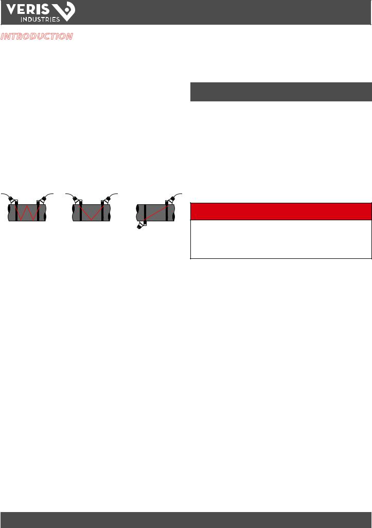
The Veris family of transit time flow meters utilize two transducers that function as both ultrasonic transmitters and receivers. The transducers are clamped on the outside of a closed pipe at a specific distance from each other. The transducers can be mounted in V-Mount where the sound transverses the pipe two times,
W-Mount where the sound transverses the pipe four times, or in Z-Mount where the transducers are mounted on opposite sides of the pipe and the sound crosses the pipe once. The selection of mounting method is based on pipe and liquid characteristics that both have an effect on how much signal is generated. The flow meter operates by alternately transmitting and receiving a frequency modulated burst of sound energy between the two transducers and measuring the time interval that it takes for sound to travel between the two transducers. The difference in the time interval measured is directly related to the velocity of the liquid in the pipe.
Because the transducers are non-contacting and have no moving parts, the flow meter is not affected by system pressure, fouling, or wear. FST4 and FST5 transducers are rated to a pipe surface temperature of -40 to +250 °F (-40 to +121 °C). FST1, FST2, and FST3 small pipe transducers are rated from -40 to +185 °F (-40 to +85 °C).
Frequency |
Transducers |
Transmission |
Pipe Size and |
|
|
Modes |
Type |
2 MHz |
All ½”thru 1½” |
Selected by |
Specific to |
|
2”Tubing |
Firmware |
Transducer |
1 MHz |
2”ANSI and Copper |
Selected by |
Specific to |
|
Firmware |
Transducer |
|
|
|
||
|
all 2”to 24” |
W, V, and Z |
2”to 24” |
|
|
|
|
500 kHz |
larger than 24” |
W, V, and Z |
24”and Greater |
|
|
|
|
User Safety
The FSR Series employs modular construction and provides electrical safety for the operator. The display face contains voltages no greater than 28 VDC. The display face swings open to allow access to user connections.
TOP VIEW |
TOP VIEW |
TOP VIEW |
OF PIPE |
OF PIPE |
OF PIPE |
W-Mount V-Mount  Z-Mount
Figure 1.1 - Ultrasound Transmission
Application Versatility
The FSRxxxx flow meter can be successfully applied on a wide range of metering applications. The simple-to-program monitor allows the standard product to be used on pipe sizes ranging from ½ inch to 100 inches (12 mm to 2540 mm) pipe*. A variety of liquid applications can be accommodated:
ultrapure liquids
potable water
chemicals
sewage
reclaimed water
cooling water
river water
plant effluent
others

 DANGER
HAZARD OF ELECTRIC SHOCK, EXPLOSION, OR ARC FLASH
•Disconnect electrical power before opening the instrument enclosure.
•Wiring must conform to applicable codes.
Failure to follow these instructions will result in death or serious injury.
Data Integrity
Non-volatile flash memory retains all user-entered configuration values in memory for several years at 77°F (25°C), even if power is lost or turned off. Password protection is provided as part of the Security menu (SEC MENU) and prevents inadvertent configuration changes or totalizer resets.
Product Identification
The serial number and complete model number of the monitor are located on the top outside surface of the housing. If technical assistance is required, please provide the Customer Service Department with this information.
Z205739-0D |
PAGE 6 |
©2013 Veris Industries USA 800.354.8556 or +1.503.598.4564 / support@veris.com |
05131 |
Alta Labs, Enercept, Enspector, Hawkeye, Trustat, Aerospond, Veris, and the Veris ‘V’ logo are trademarks or registered trademarks of Veris Industries, L.L.C. in the USA and/or other countries.

FSRxxxx SERIES
TM
INSTALLATION GUIDE
PART 1 - MONITOR INSTALLATION
After unpacking, save the shipping carton and packing materials in case the instrument is stored or re-shipped. Inspect the equipment and carton for damage. If there is evidence of shipping damage, notify the carrier immediately.
Mount the enclosure in an area that is convenient for servicing, calibration, and observation of the LCD readout.
1.Locate the monitor within the length of transducer cables supplied. If this is not possible, it is recommended that the cable be exchanged for one that is of proper length. If additional cable is added, utilize RG59 75 Ω coaxial cable and BNC connections. Transducer cables that are up to 990 feet (300 meters) can be accommodated.
Transducer Connections
To access terminal strips for wiring, loosen the two screws in the enclosure door and open.
Guide the transducer terminations through the monitor conduit hole located in the bottom-left of the enclosure. Secure the transducer cable with the supplied conduit nut (if flexible conduit was ordered with the transducer).
The terminals within the unit are of a screw-down barrier terminal type. Connect the appropriate wires at the corresponding screw terminals in the monitor. Observe upstream and downstream (+/–) orientation. See Figure 1.3.
2. Mount the monitor in a location:
•Where little vibration exists.
•That is protected from corrosive fluids.
•That is within the monitor’s ambient temperature limits -40 to +185°F (-40 to +85°C).
•That is out of direct sunlight. Direct sunlight may increase monitor temperature to above the maximum limit.
3.Mounting - Refer to Figure 1.2 for enclosure and mounting dimension details. Ensure that enough room is available to allow for door swing, maintenance and conduit entrances. Secure the enclosure to a flat surface with two appropriate fasteners.
6.4” |
|
|
4.1” |
||||
(163 mm) |
(105 |
mm) |
|||||
6.0” |
|
|
|
|
|
||
|
|
|
|
||||
(153 mm) |
|
|
|
|
|
|
|
4.3” (110 mm)
|
2.1” |
0.75” |
(53 mm) |
|
|
(19 mm) |
|
2x 0.5” |
|
(13 mm) |
|
1.4” |
|
Figure 1.2 - FSR Dimensions
4.Conduit Holes - Conduit holes should be used where cables enter the enclosure. Holes not used for cable entry should be sealed with plugs.
Note: Use NEMA 4 [IP-65] rated fittings/plugs to maintain the watertight integrity of the enclosure. Generally, the right conduit hole (viewed from front) is used for power, the left conduit hole for transducer connections, and the center hole is utilized for I/O wiring.
|
|
|
|
|
|
|
|
|
|
|
|
|
372 |
|
O N |
|
|
|
|
|
|
|
|
|
|
|
|
1500mA250V |
|
1 |
|
|
|
|
|
|
|
|
|
|
|
|
W |
|
2 |
|
|
|
|
|
|
|
|
|
|
|
|
|
|
3 |
|
|
|
|
|
|
|
|
|
|
|
|
|
|
4 |
AModbus |
Gnd Modbus |
Total Reset |
Out mA 20-4 |
OutFrequency |
2 Control |
1 Control |
.Gnd Signal |
|
|
ACL |
|
|
|
|
NeutralAC |
VAC264 - 95 |
US |
:OUTDC |
PWC -100:INAC |
|||||||||
|
ModbusB |
R RoHSTUV |
|
0 |
strodynecom ACN |
|||||||||
|
|
|
|
|
|
|
|
|
|
|
C |
|
|
|
|
|
|
|
|
|
|
|
|
|
|
E167432 |
3A.0/+15V |
|
. www |
+ |
Downstream |
|
|
|
|
|
|
|
|
|
|
|
.astrodyne |
|
- |
|
|
|
|
|
|
|
|
|
|
|
|
15E 240VAC,50/60Hz |
|
|
|
|
|
|
|
|
|
|
|
|
|
|
- |
|
- |
Upstream |
|
|
|
|
|
|
|
|
|
|
R2807 |
15A. |
+Vo |
+ |
Modbus RxTFX TFX |
|
|
|
|
|
|
|
|
|
Vo- |
|||
|
|
|
|
|
|
|
|
|
|
|
|
|
|
|
To Transducers |
Note: Wire colors may vary! |
|
|
|
(+) connection with be either red or blue; |
Figure 1.3 - Transducer Connections. |
(–) connection will be either black or clear. |
|
Note: The transducer cable carries low level, high frequency signals. Do not add length to the cable supplied with the transducers. If additional cable is required, contact the manufacturer to arrange an exchange for a transducer with the appropriate length of cable. Cables to 990 feet (300 meters) are available. If adding cable, ensure that it is RG59 75 Ω compatible and uses BNC terminations.
Connect power to the screw terminal block in the monitor. See Figure 1.4 and Figure 1.5. Utilize the conduit hole on the right side of the enclosure for this purpose. Use wiring practices that conform to local and national codes (e.g., The National Electrical Code® Handbook in the U.S.).
 CAUTION
•HAZARD OF IMPROPER OR UNSAFE OPERATION
•This instrument requires clean electrical line power. Do not operate this unit on
circuits with noisy components (e.g., fluorescent lights, relays, compressors, or variable frequency drives).
•Do not use with high current step-down transformers from high voltage sources.
•Do not run signal wires with line power in the same wiring tray or conduit.
Any other wiring method may be unsafe or cause improper operation of the instrument.
Z205739-0D |
PAGE 7 |
©2013 Veris Industries USA 800.354.8556 or +1.503.598.4564 / support@veris.com |
05131 |
Alta Labs, Enercept, Enspector, Hawkeye, Trustat, Aerospond, Veris, and the Veris ‘V’ logo are trademarks or registered trademarks of Veris Industries, L.L.C. in the USA and/or other countries.

FSRxxxx SERIES
TM
INSTALLATION GUIDE
AC Power Connections
Connect 90 to 265 VAC, AC Neutral and Chassis Ground to the terminals referenced in Figure 1.4. Do not operate without an earth (chassis) ground connection.
ACN |
strodyne |
|
+Vo |
|||
|
www.astrodyne.com |
|
|
|||
W USC 1500mA250V D VE 372 |
PWC-15E |
0.15A |
-Vo |
|||
AC IN : 100-240VAC,50/60Hz |
||||||
|
DC OUT : +15V / 0.3A |
|
R2807 |
|||
|
R |
TUV |
RoHS |
|||
ACL |
C E167432 US |
|
|
|||
|
|
|
|
|
||
|
95 - 264 VAC |
|
|
|
|
|
|
AC Neutral |
|
|
|
|
|
Signal Gnd. |
|
|
|
|
|
|
Control 1 |
|
|
|
|
|
|
Control 2 |
|
|
|
|
|
|
Frequency Out |
|
|
|
|
||
4-20 mA Out |
|
|
|
|
||
Reset Total |
|
|
|
|
|
|
Modbus Gnd |
|
|
|
Modbus |
||
Modbus B |
|
|
|
|
||
|
|
|
|
TFX Rx |
||
Modbus A |
Downstream |
|
|
|
TFX Tx |
|
|
|
|
|
Upstream |
|
|
O 1 |
2 |
3 |
4 |
+ - - + |
|
||||
N |
|
|
|
|
Figure 1.4 - AC Power Connections
Note: In electrically noisy applications, ground the meter to the pipe where the transducers are mounted to provide additional noise suppression. This approach is only effective with conductive metal pipes. Remove the earth (chassis) ground derived from the line voltage power supply at the meter and connect a new earth ground between the meter and the pipe being measured.
Note: The terminal blocks accomodate wire gauges up to 14 AWG.
Note: AC powered versions are protected by a field replaceable fuse. This fuse is equivalent to Littelfuse/Wickmann P.N. 3720500041 or 37405000410.
DC Power Connections
The device can be operated from a 10 to 28 VDC source, as long as the source is capable of supplying a minimum of 5 Watts of power.
Connect the DC power to 10 to 28 VDC In, Power Gnd., and Chassis Gnd., as in Figure 1.5.


 10 - 28 VDC
Power Gnd.
Signal Gnd. |
|
|
Control 1 |
|
|
Control 2 |
|
|
Frequency Out |
|
|
4-20 mA Out |
|
|
Reset Total |
|
|
Modbus Gnd |
Modbus |
|
Modbus B |
||
TFX Rx |
||
Modbus A |
TFX Tx |
|
Downstream |
Upstream |
O 1 |
2 |
3 |
4 |
+ - - + |
|
||||
N |
|
|
|
|
10 -28 VDC
Power
Ground
Figure 1.5 - DC Power Connections
Note: DC powered versions are protected by an automatically resetting fuse. This fuse does not require replacement.
Z205739-0D |
PAGE 8 |
©2013 Veris Industries USA 800.354.8556 or +1.503.598.4564 / support@veris.com |
05131 |
Alta Labs, Enercept, Enspector, Hawkeye, Trustat, Aerospond, Veris, and the Veris ‘V’ logo are trademarks or registered trademarks of Veris Industries, L.L.C. in the USA and/or other countries.

FSRxxxx SERIES
TM
INSTALLATION GUIDE
PART 2 - TRANSDUCER INSTALLATION
General
The FST transducers contain piezoelectric crystals for transmitting and receiving ultrasonic signals through walls of liquid piping systems. FST transducers are relatively simple and straightforward to install, but spacing and alignment of the transducers is critical to the system’s accuracy and performance. Take care to ensure that these instructions are carefully executed. FST1, FST2, and FST3 small pipe transducers have integrated transmitter and receiver elements that eliminate the requirement for spacing measurement and alignment.
Mounting of the FST4 and FST5 clamp-on ultrasonic transit time transducers is a three-step process:
1.Select the optimum location on a piping system.
2.Enter the pipe and liquid parameters into either the software utility or key the parameters into the transmitter using the keypad. The software utility or the monitor’s firmware calculates proper transducer spacing based on these entries.
3.Pipe preparation and transducer mounting.
BTU meters require two RTDs to measure heat usage. The flow meter utilizes 1,000 Ω, three-wire, platinum RTDs in two mounting styles. Surface mount RTDs are available for use on well insulated pipes. Mounting the RTD in an uninsulated area causes inconsistent temperature readings. Insertion (wetted) RTDs should be sued in these areas instead.
Step 1 - Mounting Location
The first step in the installation process is the selection of an optimum location for the flow measurement to be made. This requires a basic knowledge of the piping system and its plumbing.
An optimum location is defined as:
•A piping system that is completely full of liquid when measurements are being taken. The pipe may become completely empty during a process cycle, which results in the error code 0010 (Low Signal Strength) being displayed on the flow meter while the pipe is empty. This error code clears automatically once the pipe refills with liquid. It is not recommended to mount the transducers in an area where the pipe may become partially filled. Partially filled pipes cause erroneous and unpredictable operation of the meter.
•A piping system that contains lengths of straight pipe such as those described in Table 2.1. The optimum straight pipe diameter recommendations apply to pipes in both horizontal and vertical
orientation. The straight runs in Table 2.1 apply to liquid velocities that are nominally 7 FPS (2.2 MPS). As liquid velocity increases above this nominal rate, the requirement for straight pipe increases proportionally.
•Mount the transducers in an area where they will not be inadvertently bumped or disturbed during normal operation.
•Avoid installations on downward flowing pipes unless adequate downstream head pressure is present to overcome partial filling of or cavitation in the pipe.
•Note: Do not cut transducer cables to alter length. This will void the factory warranty. Cables are available in several lengths. Assess the installation location prior to ordering to determine the optimum length. If the wrong length is ordered, contact the factory.
Piping Configuration and Transducer Positioning Upstream |
Downstream |
|
|
Pipe |
Pipe |
|
Diameters |
Diameters |
|
* |
** |
|
25 |
5 |
Flow |
|
|
|
14 |
5 |
Flow |
|
|
* |
** |
|
|
10 |
5 |
 Flow
Flow
 *
* 
 **
**

10 5
Flow
* 
 **
**

10 5
Flow
* 
 **
**

24 5

 Flow
Flow
 *
* 
 **
**
Table 2.1 - Piping Configuration and Transducer Positioning
The flow meter system provides repeatable measurements on piping systems that do not meet these requirements, but accuracy of these readings may be influenced to various degrees.
Step 2 - Transducer Spacing
Transit time flow meters can be used with two different transducer types. Meters that utilize the FST4 and FST5 transducer sets consist of two separate sensors that function as both ultrasonic transmitters and receivers. FST1, FST2, and FST3
transducers integrate both the transmitter and receiver into one assembly that fixes the separation of the piezoelectric crystals. These transducers are clamped on the outside of a closed pipe at a specific distance from each other.
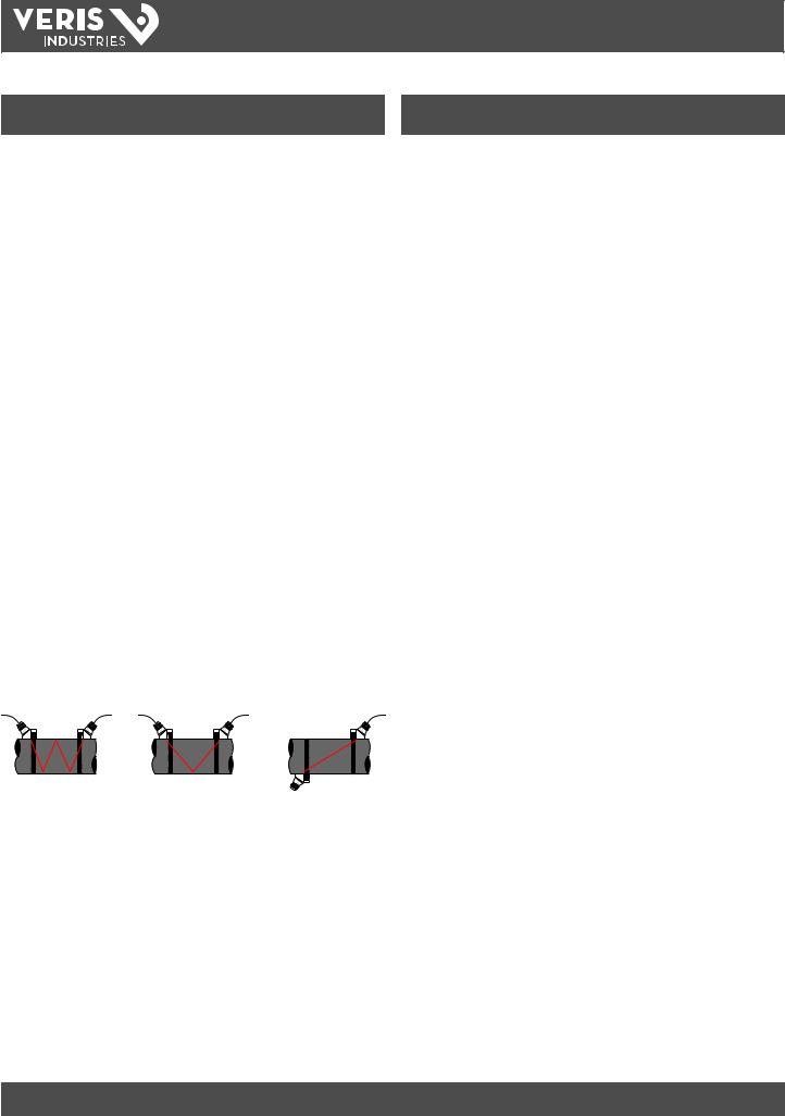
The FST4 and FST5 transducers can be mounted in:
W-Mount where the sound traverses the pipe four times. This mounting method produces the best relative travel time values but the weakest signal strength.
V-Mount where the sound traverses the pipe twice. V-Mount is a compromise between travel time and signal strength.
Z-Mount where the transducers are mounted on opposite sides of the pipe and the sound crosses the pipe once. Z-Mount will yield the best signal strength but the smallest relative travel time.
Z205739-0D |
PAGE 9 |
©2013 Veris Industries USA 800.354.8556 or +1.503.598.4564 / support@veris.com |
05131 |
Alta Labs, Enercept, Enspector, Hawkeye, Trustat, Aerospond, Veris, and the Veris ‘V’ logo are trademarks or registered trademarks of Veris Industries, L.L.C. in the USA and/or other countries.
FSRxxxx SERIES
TM
INSTALLATION GUIDE
Mounting |
Pipe Material |
Pipe Size |
Liquid |
|
Mode |
|
|
Composition |
|
|
Plastic (all types) |
|
|
|
|
|
|
|
|
|
Carbon Steel |
2-4 in. (50-100 mm) |
|
|
W-Mount |
Stainless Steel |
|
||
|
|
|||
|
|
|
||
Copper |
|
|
||
|
|
|
||
|
|
|
|
|
|
Ductile Iron |
Not Recommended |
|
|
|
Cast Iron |
|
||
|
|
|
||
|
|
|
|
|
|
Plastic (all types) |
|
|
|
|
|
|
|
|
|
Carbon Steel |
4-12 in. (100-300 mm) |
|
|
V-Mount |
Stainless Steel |
|
Low TSS; non-aerated |
|
|
|
|||
Copper |
4-30 in. (100-750 mm) |
|||
|
|
|||
|
|
|
|
|
|
Ductile Iron |
2-12 in. (50-300 mm) |
|
|
|
Cast Iron |
|
||
|
|
|
||
|
|
|
|
|
|
Plastic (all types) |
> 30 in. (>750 mm) |
|
|
|
|
|
|
|
|
Carbon Steel |
>12 in. (>300 mm) |
|
|
Z-Mount |
Stainless Steel |
|
||
|
|
|||
|
|
|
||
Copper |
> 30 in. (>750 mm) |
|
||
|
|
|||
|
|
|
|
|
|
Ductile Iron |
>12 in. (>300 mm) |
|
|
|
Cast Iron |
|
||
|
|
|
||
|
|
|
|
Table 2.2 - Transducer Mounting Modes — FST4, FST5
For further details, reference Figure 2.1. The appropriate mounting configuration is based on pipe and liquid characteristics. Selection of the proper transducer mounting method is not entirely predictable and many times is an iterative process. Table 2.2 contains recommended mounting configurations for common applications. These recommended configurations may need to be modified for specific applications
if such things as aeration, suspended solids, out of round piping or poor piping conditions are present. Use of meter diagnostics in determining the optimum transducer mounting is covered later in this section.
TOP VIEW |
TOP VIEW |
TOP VIEW |
OF PIPE |
OF PIPE |
OF PIPE |
W-Mount V-Mount  Z-Mount
Figure 2.1- Transducer Mounting Modes — FST4, FST5
Size |
Frequency |
Transducer |
Mounting Mode |
|
Setting |
|
|
|
|
FST1 |
|
1/2 |
2 MHz |
|
|
FST2 |
|
||
|
|
FST3 |
|
|
|
|
|
|
|
FST1 |
|
|
|
|
|
3/4 |
2 MHz |
FST2 |
|
|
|
FST3 |
|
|
|
|
|
|
|
FST1 |
|
|
|
|
|
1 |
2 MHz |
FST2 |
|
|
|
FST3 |
V |
|
|
|
|
|
|
FST1 |
|
|
|
|
|
|
|
|
|
1 1/4 |
2 MHz |
FST2 |
|
|
|
FST3 |
|
|
|
|
|
|
|
FST1 |
|
|
|
|
|
1 1/2 |
2 MHz |
FST2 |
|
|
|
FST3 |
|
|
|
|
|
|
1 MHz |
FST1 |
|
2 |
|
|
|
FST2 |
|
||
|
|
||
|
2 MHz |
FST3 |
|
|
|
|
|
Table 2.3 - Transducer Mounting Modes — FST1, FST2, FST3
Step 3 - Entering Pipe and Liquid Data
The system calculates proper transducer spacing by utilizing piping and liquid information entered by the user. Enter this information via the keypad or via the optional software utility.
The best accuracy is achieved when transducer spacing is exactly what the meter calculates, so use the calculated spacing if signal strength is satisfactory. If the pipe is not round, the wall thickness is not correct, or the actual liquid being measured has a different sound speed than the liquid programmed into the transmitter, the spacing can vary from the calculated value. If that is the case, place the transducers sat the highest signal level observed by moving the transducers slowly around the mount area.
Note: Transducer spacing is calculated on “ideal” pipe. Ideal pipe is almost never found so the transducer spacing distances may need to be altered. An effective way to maximize signal strength is to configure the display to show signal strength, fix one transducer on the pipe and then starting at the calculated spacing, move the remaining transducer small distances forward and back to
find the maximum signal strength point.
Important! Enter all of the data on this list, save the data, and reset the meter before mounting transducers.
Z205739-0D |
PAGE 10 |
©2013 Veris Industries USA 800.354.8556 or +1.503.598.4564 / support@veris.com |
05131 |
Alta Labs, Enercept, Enspector, Hawkeye, Trustat, Aerospond, Veris, and the Veris ‘V’ logo are trademarks or registered trademarks of Veris Industries, L.L.C. in the USA and/or other countries.
FSRxxxx SERIES
TM
INSTALLATION GUIDE
The following information is required before programming the instrument:
Transducer mounting configuration |
Pipe O.D. (Outer Diameter) |
|
|
Pipe wall thickness |
Pipe material |
|
|
Pipe sound speed1 |
Pipe relative roughness1 |
Pipe liner thickness (if present) |
Pipe liner material (if present) |
|
|
Fluid type |
Fluid sound speed1 |
Fluid viscosity1 |
Fluid specific gravity1 |
Note: Much of the data relating to material sound speed, viscosity, and specific gravity is pre-programmed into the flow meter. This data only needs to be modified if it is known that a particular applications data varies from the reference values. Refer to Part 4 of this manual for instructions on entering configuration data into the flow meter via the monitor’s keypad. Refer to
Part 5 for data entry via the software.
|
|
|
TOP OF PIPE |
|
|
|
45° |
45° |
|
|
|
YES |
YES |
|
|
|
45° |
45° |
|
|
TOP OF PIPE |
|
FLOW METER MOUNTING |
TOP OF PIPE |
|
|
ORIENTATION |
||
|
|
|
|
|
|
|
|
FST4, FST5 TRANSDUCERS |
|
45° |
|
45° |
45° |
45° |
|
YES |
YES |
YES |
YES |
|
|
|
|
|
45° |
|
45° |
45° |
45° |
|
FLOW METER |
|
|
FLOW METER |
|
MOUNTING ORIENTATION |
|
|
MOUNTING ORIENTATION |
|
2” FST1, FST2, FST3 TRANSDUCERS |
<2” FST1, FST2, FST3 TRANSDUCERS |
||
1 Nominal values for these parameters are included within the operating system. The nominal values may be used as they appear or may be modified if exact system values are known.
After entering the data listed above, the meter calculates proper transducer spacing for the particular data set. This distance is in inches if it is configured in English units, or millimeters if configured in metric units.
Step 4 - Transducer Mounting
Pipe Preparation
Before mounting the transducers onto the pipe surface, clean an area slightly larger than the flat surface of each transducer to eliminate all rust, scale and moisture. For pipes with rough surfaces, such as ductile iron pipe, wire brush the surface to a
shiny finish. Paint and other coatings need not be removed unless flaked or bubbled. Plastic pipes typically do not require surface preparation other than soap and water cleaning.
Properly orient the transducers and spaced them on the pipe to provide optimum reliability and performance. On horizontal pipes, when Z-Mount is required, mount the transducers 180 radial degrees from one another and at least 45 degrees from the top-dead-center and bottom-dead-center of the pipe. See Figure 2.2 Also see Z-Mount Transducer Installation. On vertical pipes the orientation is not critical.
Measure the spacing between the transducers using the two spacing marks on the sides of the transducers. These marks are approximately 0.75” (19 mm) back from the nose of the FST4/FST5 transducers. See Figure 2.3.
Mount FST1, FST2, and FST3 transducers with the cable exiting within ±45 degrees of the side of a horizontal pipe. See Figure 2.2. On vertical pipes the orientation does not apply.
Figure 2.2 - Transducer Orientation — Horizontal Pipes
Alignment
Marks
Figure 2.3 - Transducer Alignment Marks
V-Mount and W-Mount Installation
Application of Couplant
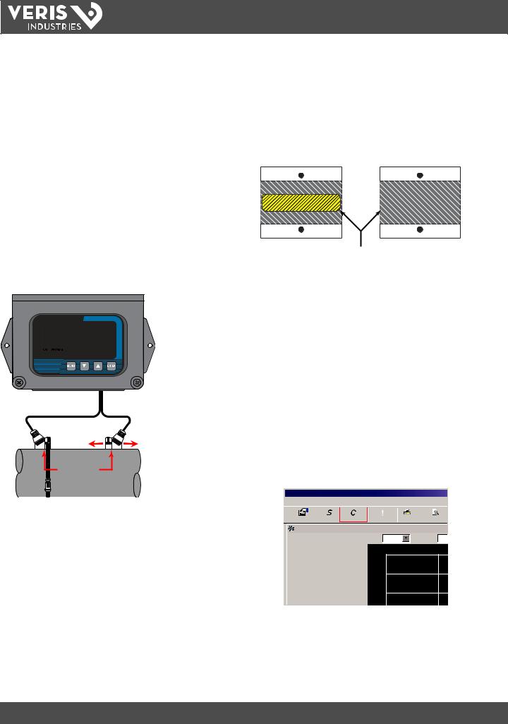
For FST4 and FST5 transducers, place a single bead of couplant, approximately ½ inch (12 mm) thick, on the flat face of the transducer. See Figure 2.4. Generally, a silicone-based grease is used as an acoustic couplant, but any grease-like substance that is rated not to “flow” at the temperature that the pipe may operate at will be acceptable. For pipe surface temperature over 130°F (55°C) Sonotemp® (P.N. D002- 2011-010) is recommended.
½”
(12 mm)
Figure 2.4 - Application of Couplant
Z205739-0D |
PAGE 11 |
©2013 Veris Industries USA 800.354.8556 or +1.503.598.4564 / support@veris.com |
05131 |
Alta Labs, Enercept, Enspector, Hawkeye, Trustat, Aerospond, Veris, and the Veris ‘V’ logo are trademarks or registered trademarks of Veris Industries, L.L.C. in the USA and/or other countries.
FSRxxxx SERIES
TM
INSTALLATION GUIDE
Transducer Positioning
1.Place the upstream transducer in position and secure with a mounting strap. Place straps in the arched groove on the end of the transducer. A screw is provided to help hold the transducer onto the strap. Tighten the transducer strap securely.
2.Place the downstream transducer on the pipe at the calculated transducer spacing. See Figure 2.5. Apply firm hand pressure. If signal strength is greater than 5, secure the transducer at this location. If the signal strength is not 5 or greater then using firm hand pressure, slowly move the transducer both towards and away from the upstream transducer while observing signal strength. Clamp thetransducer where the highest signal strength is observed. Signal levels much less than 5 may not yield acceptable data.
Note: Signal strength readings update only every few seconds, so it is advisable to move the transducer 1/8”, wait, see if signal is increasing or decreasing and then repeat until
the highest level is achieved.
3.If after adjustment of the transducers the signal strength does not rise to above 5, then select an alternate transducer mounting method. If the mounting method was W-Mount, then re-configure the monitor for V-Mount, move the downstream transducer to the new spacing distance and repeat Step 4.
Transducer
Spacing
Figure 2.5 - Transducer Positioning
Small Pipe Transducer Installation
The small pipe transducers are designed for specific pipe outside diameters. Do not attempt to mount a transducer onto a pipe that is either too large or too small for the transducer.
FST1, FST2, and FST3 installation consists of the following steps:
1.Apply a thin coating of acoustic coupling grease to both halves of the transducer housing where the housing will contact the pipe. See Figure 2.6.
1/16” (1.5 mm) Acoustic Couplant Grease
Figure 2.6 - Application of Acoustic Couplant — FST1, FST2, FST3 Transducers
2.On horizontal pipes, mount the transducer in an orientation such that the cable exits at ±45 degrees from the side of the pipe. Do not mount with the cable exiting on either the top or bottom of the pipe. On vertical pipes the orientation does not matter. See Figure 2.2.
3.Tighten the wing nuts or “U” bolts so that the acoustic coupling grease begins to flow out from the edges of the transducer or from the gap between the transducer halves. Do not over tighten.
4.If signal strength is less than 5, remount the transducer at another location on the piping system.
5.Configuration Procedure:
a.Establish communications with the transit tme meter. See Part 5 - Software Utility.
b.From the tool bar, select calibration.
 USP - Device Addr 127
File Edit View Communications Window Help
Configuration Strategy Calibration |
! |
|
Print Previe |
||
Errors |
|
||||
Device Addr 127 |
|
|
|
|
|
|
|
Time: 60 Min |
|
Scale: 200 |
|
|
|
2000 |
|
|
|
Flow: |
1350 Gal/Min |
|
|
|
|
Totalizer Net: |
0 OB |
|
|
|
|
Pos: |
0 OB |
1600 |
|
|
|
Neg: |
0 OB |
|
|
|
|
Sig. Strength: |
15.6% |
|
|
|
|
Margin: |
100% |
1200 |
|
|
|
Delta T: |
-2.50 ns |
|
|
|
|
|
|
|
|
||
Last Update: |
09:53:39 |
|
|
|
|
c. On the pop-up screen, click Next twice to get to page 3 of 3. Click Edit in this screen.
Z205739-0D |
PAGE 12 |
©2013 Veris Industries USA 800.354.8556 or +1.503.598.4564 / support@veris.com |
05131 |
Alta Labs, Enercept, Enspector, Hawkeye, Trustat, Aerospond, Veris, and the Veris ‘V’ logo are trademarks or registered trademarks of Veris Industries, L.L.C. in the USA and/or other countries.

FSRxxxx SERIES
TM
INSTALLATION GUIDE
Calibration (Page 3 of 3) - Linearization
28.2
Gal/M
Delta Time
1) Please establish a reference flow rate.
1FPS / 0.3MPS Minimum.
2)Enter the reference flow rate below. (Do not enter 0)
3)Wait for flow to stabilize.
4)Press the Set button.
Flow:
Set
Edit
Export...
d.In the Calibration Points Editor screen, use the Add and Remove buttons as needed. Click OK when complete.
e.The display returns to Calibration (Page 3 of 3). Click finish
f.Power cycle the unit to activate the new settings.
Mounting Transducers in Z-Mount Configuration
Installation on larger pipes requires careful measurements of the linear and radial placement of the FST4 and FST5 transducers. Failure to properly orient and place the transducers on the pipe may lead to weak signal strength and/or inaccurate readings.
1.Place the transducers on opposite sides of the pipe. This distance around the pipe is calculated by multiplying the pipe diameter by 1.57. The transducer spacing along the pipe is the same as found in the Transducer Positioning section.
2.For FST4 and FST5 transducers, place a single bead of couplant, approximately ½ inch (12 mm) thick, on the flat face of the transducer. See Figure 2.4. Generally, a silicone-based grease is used as an acoustic couplant, but any good quality grease-like substance that is rated to not “flow” at the temperature that the pipe may operate at is acceptable.
3.Place the upstream transducer in position and secure with a stainless steel strap or other fastening device. Place straps in the arched groove on the end of the transducer. A screw is provided to help hold the transducer onto the strap. Tighten transducer strap securely. Larger pipes may require more than one strap to reach the circumference of the pipe.
4.Place the downstream transducer on the pipe at the calculated transducer spacing. See Figure 2.7. Using firm hand pressure, slowly move the transducer both towards and away from the upstream transducer while observing signal strength. Clamp the transducer at the position where the highest signal strength is observed. Signal strength of between 5 and 98 is acceptable. The factory default signal strength setting is 5, however there are many application specific conditions that may prevent the signal strength from attaining this level.
A minimum signal strength of 5 is acceptable as long as this signal level is maintained under all flow conditions. On certain pipes, a slight twist to the transducer may cause signal strength to rise to acceptable levels.
5.Certain pipe and liquid characteristics may cause signal strength to rise to greater than 98. At this level, the signals may saturate the input amplifiers and cause erratic readings. To lower the signal strength, change the transducer mounting method to the next longest transmission path. For example, if there is excessive signal strength and the transducers are mounted in a Z-Mount, try changing to
V-Mount or W-Mount. Finally you can also move one transducer slightly off line with the other transducer to lower signal strength.
6.Secure the transducer with a stainless steel strap or other fastener.
|
TOP OF PIPE |
|
TOP VIEW |
PIPE CROSS |
|
SECTIONAL |
||
OF PIPE |
||
VIEW |
||
|
Distance = Pipe Outer Diameter * 1.57
Figure 2.7 - Z-Mount Transducer Placement
Z205739-0D |
PAGE 13 |
©2013 Veris Industries USA 800.354.8556 or +1.503.598.4564 / support@veris.com |
05131 |
Alta Labs, Enercept, Enspector, Hawkeye, Trustat, Aerospond, Veris, and the Veris ‘V’ logo are trademarks or registered trademarks of Veris Industries, L.L.C. in the USA and/or other countries.

FSRxxxx SERIES
TM
INSTALLATION GUIDE
PART 3 - INPUTS/OUTPUTS
General
The FSR1 is available in two configurations: the flow model and the energy model. The flow model is equipped with a 4-20 mA output, two open collector outputs, a rate frequency output, and RS-485 communications using the Modbus RTU command set. The energy version has inputs for two 1,000 Ω RTD sensors in place of the rate frequency and alarm outputs. This version allows the measurement of pipe input and output temperatures for calculating energy usage calculations.
4-20 mA Output
The 4-20 mA output interfaces with most recording and logging systems by transmitting an analog current signal that is proportional to system flow rate. The 4-20 mA output is internally powered (current sourcing) and can span negative to positive flow/energy rates.
90-265 VAC
|
AC Neutral |
Signal Ground |
|
Signal Gnd. |
|
Loop |
Control 1 |
|
Control 2 |
|
|
Resistance |
|
|
Frequency Out |
|
|
|
|
|
|
4-20 mA Out |
|
|
Reset Total |
|
7 VDC
Drop
Meter Power
For AC powered units, the 4-20 mA output is driven from a +15 VDC source located within the meter, isolated from earth ground connections. The AC powered model accommodates loop loads up to 400 Ω. DC powered meters utilize the DC power supply voltage to drive the current loop. The current loop is not isolated from DC ground or power. Figure 3.1 shows graphically the allowable loads for various input voltages. The combination of input voltage and loop load must stay within the shaded area of Figure 3.1.
|
|
|
Supply Voltage - 7 VDC |
= Maximum Loop Resistance |
|
|||||
|
|
|
|
0.02 |
|
|
||||
|
|
|
|
|
|
|
|
|
|
|
|
1100 |
|
|
|
|
|
|
|
|
|
|
1000 |
|
|
|
|
|
|
|
|
|
(Ohms) |
900 |
|
|
|
|
|
|
|
|
|
800 |
|
|
|
|
|
|
|
|
|
|
|
|
|
|
|
|
|
|
|
|
|
|
700 |
|
|
|
|
|
|
|
|
|
Load |
600 |
|
|
|
|
|
|
|
|
|
500 |
|
|
|
|
Operate in the |
|
||||
Loop |
|
|
|
|
|
|||||
400 |
|
|
|
|
|
|||||
|
|
|
|
Shaded Regions |
|
|||||
|
|
|
|
|
|
|||||
|
300 |
|
|
|
|
|
||||
|
200 |
|
|
|
|
|
|
|
|
|
|
10010 |
12 |
14 |
16 |
18 |
20 |
22 |
24 |
26 |
28 |
Supply Voltage (VDC)
Figure 3.1 - Allowable Loop Resistance (DC Powered Units)
Figure 3.2 - 4-20 mA Output
The 4-20 mA output signal is available between the 4-20 mA Out and Signal Gnd. terminals as shown in Figure 3.2.
Control Outputs
Two independent open collector transistor outputs are included with the flow meter. Each output can be configured for one of the following four functions:
Rate Alarm
Signal Strength Alarm
Totalizing/Totalizing Pulse
Errors
None
Both control outputs are rated for a maximum of 100 mA and 10 to 28 VDC. A pull-up resistor can be added externally or an internal 10 kΩ pull-up resistor can be selected using DIP switches on the power supply board.
O 1 2 3 4
N
Figure 3.3 - Switch Settings
Switch |
S1 |
S2 |
S3 |
S4 |
On |
Control 1 pull-up; |
Control 2 pull-up; |
Frequency output |
Square wave |
|
Resistor IN circuit |
Resistor IN circuit |
pull-up; |
output |
|
|
|
Resistor IN circuit |
|
Off |
Control 1 pull-up; |
Control 2 pull-up; |
Frequency output |
Simulated turbine |
|
Resistor OUT OF |
Resistor OUT OF |
pull-up; |
output |
|
circuit |
circuit |
Resistor OUT OF |
|
|
|
|
circuit |
|
Table 3.1 - DIP Switch Functions |
|
|
|
|
Z205739-0D PAGE 14 ©2013 Veris Industries USA 800.354.8556 or +1.503.598.4564 / support@veris.com 05131
Alta Labs, Enercept, Enspector, Hawkeye, Trustat, Aerospond, Veris, and the Veris ‘V’ logo are trademarks or registered trademarks of Veris Industries, L.L.C. in the USA and/or other countries.

FSRxxxx SERIES
TM
INSTALLATION GUIDE
Set the on/off values for the Rate Alarm and Signal Strength Alarm using either the keypad or the software utility.
Typical control connections are illustrated in Figure 3.4. Please note that only the Control 1 output is shown. Control 2 is identical except the pull-up resistor is governed by SW2.
|
|
VCC |
|
|
|
|
|
|
|
|
|
|
|
|
10K |
|
|
|
|
|
|
|
|
|
|
90-265 VAC |
O 1 |
2 3 |
4 |
SW1/SW2 |
|
90-265 VAC |
O |
1 |
2 |
3 |
4 |
|
N |
|
|
10 - 28 |
N |
SW1/SW2 |
|||||||
AC Neutral |
|
|
|
AC Neutral |
|
|
|
|
|
|||
Signal Gnd. |
|
|
|
|
VDC |
|
|
|
|
|
|
|
|
|
|
|
Signal Gnd. |
|
|
|
|
|
|
||
Control 1 |
|
|
|
|
|
|
|
|
|
|
|
|
|
|
|
|
|
Control 1 |
|
|
|
|
|
|
|
Control 2 |
|
|
|
|
|
|
|
|
|
|
|
|
|
|
|
|
|
Control 2 |
|
|
|
|
|
|
|
Frequency Out |
|
|
|
|
|
|
|
|
|
|
|
|
|
|
|
|
|
Frequency Out |
|
|
|
|
|
|
|
4-20 mA Out |
|
|
|
|
100 mA Maximum |
|
|
|
|
|
|
|
|
|
|
|
4-20 mA Out |
|
|
|
|
|
|
||
Reset Total |
|
|
|
|
|
|
|
|
|
|
|
|
|
|
|
|
|
Reset Total |
|
|
|
|
|
|
|
|
|
|
|
|
|
|
|
|
|
|
|
|
Figure 3.4 - Typical Control Connections
Alarm Output
The flow rate output permits output changeover at two separate flow rates allowing operation with an adjustable switch deadband. Figure 3.5 illustrates how the setting of the two set points influences rate alarm operation.
A single-point flow rate alarm places the ON setting slightly higher than the OFF setting, establishing a switch deadband. If a deadband is not established, switch chatter (rapid switching) may result if the flow rate is very close to the switch point.
Minimum |
|
Maximum |
|
Flow |
|
Flow |
|
Set OFF |
Set ON |
Output ON |
|
|
|
|
|
Output OFF
Deadband
Figure 3.5 - Single Point Alarm Operation
Batch/Totalizer Output
Totalizer mode configures the output to send a 33 mSec pulse each time the display totalizer increments divided by the TOT MULT. The TOT MULT value must be a whole, positive, numerical value.
Fir example, If the totalizer exponent (TOTL E) is set to E2 (×100) and the totalizer multiplier (TOT MULT) is set to 1, then the control output pulses each time the display totalizer increments or once per 100 measurement units totalized.
Totalizer Output for Energy Meter
Energy units can be ordered with a totalizer pulse output option. This option is installed in the position where the Ethernet option would normally be; therefore, the totalizer pulse output option and the Ethernet communications output cannot be installed simultaneously.
Optional totalizing pulse specifications:
Signal |
1 pulse for each increment of the totalizer’s least significant digit |
|
|
Type |
Opto-isolated, open collector transistor |
Pulse Width |
30 msec, max. pulse rate 16 Hz |
|
|
Voltage |
28 VDC max. |
|
|
Current |
100 mA max. (current sink) |
Pull-up Resistor |
2.8 kΩ to 10 kΩ |
|
|
Wiring and configuring this option is similar to the totalizing pulse output for the flow only version. This option must use an external current limiting resistor.
Totalizing
Pulse Output |
|
VCC |
|
|
|
2.8K to 10K |
|
Option |
|
|
|
|
100 mA |
Pull-up |
|
|
|
Maximum |
Resistor |
|
Pulse |
RxD |
Isolated Output |
|
Total |
|
Total Pulse |
TB1 |
|
|
Internal
Signal Strength Alarm
The SIG STR alarm provides an indication that the signal level reported by the transducers has fallen to a point where flow measurements may not be possible. It can also be used to indicated that the pipe has emptied. Like the rate alarm
described previously, the signal strength alarm requires that two points be entered, establishing an alarm deadband. The ON value must be lower than the OFF value. If a deadband is not established and the signal strength decreases to approximately the value of the switch point, the output may “chatter.”
Error Alarm Outputs
When a control output is set to ERROR mode, the output activates when an error causes the meter to stop measuring reliably. See the Appendix of this manual for a list of potential error codes.
Z205739-0D |
PAGE 15 |
©2013 Veris Industries USA 800.354.8556 or +1.503.598.4564 / support@veris.com |
05131 |
Alta Labs, Enercept, Enspector, Hawkeye, Trustat, Aerospond, Veris, and the Veris ‘V’ logo are trademarks or registered trademarks of Veris Industries, L.L.C. in the USA and/or other countries.

FSRxxxx SERIES
TM
INSTALLATION GUIDE
Frequency Output [FSRxxx1x only]
The frequency output is an open-collector transistor circuit that outputs a pulse waveform that varies proportionally with flow rate. This type of frequency output is also know as a “Rate Pulse” output. The frequency output is proportional to the max flow rate entered into the meter. The maximum output frequency is 1000 Hz.
In addition to the control outputs, the frequency output can be used to provide total information by use of a K-factor that relates the number of pulses from the frequency output to the number of accumulated pulses that equates to a specific volume.
This relationship is described by the following equation: K-factor = 60,000 / full scale units. The 60,000 relates to measurement units in volume/min. Measurement units in seconds, hours or days would require a different numerator.
If the frequency output is to be used as a totalizing output, then the meter and the receiving instrument must have identical K-factor values programmed into them to ensure that accurate readings are recorded by the receiving instrument. Unlike standard mechanical flow meters such as turbines, gear or nutating disk meters, the K-factor can be changed by modifying the MAX RATE flow rate value.
Note: For a full treatment of K-factors please see the Appendix of this manual.
There are two frequency output types available:
1.) Turbine meter simulation - This option is utilized when a receiving instrument is capable of interfacing directly with a turbine flow meter’s magnetic pickup. The output is a relatively low voltage AC signal whose amplitude swings above and below the signal ground reference. The minimum AC amplitude is approximately 500 mV peak-to-peak. To activate the turbine output circuit, turn SW4 OFF .
500 mVp-p |
0 |
Figure 3.7 - Frequency Output Waveform (Simulated Turbine)
2.) Square-wave frequency - This option is utilized when a receiving instrument requires that the pulse voltage level be either of a higher potential and/or referenced to DC ground. The output is a square-wave with a peak voltage equaling the instrument supply voltage when the SW3 is ON.
If desired, an external pull-up resistor and power source can be utilized by leaving SW3 OFF. Set SW4 to ON for a square-wave output.
+V
0
Figure 3.8 - Frequency Output Waveform (Square Wave)
RS-485
The RS-485 feature allows up to 126 metering systems to be placed on a single threewire cable bus. Each meter is assigned a unique numeric address that allows all of the meters on the cable network to be independently accessed. A Modbus RTU command protocol is used to interrogate the meters. An explanation of the command structure is detailed in the APPENDIX of this manual. Flow rate, total, signal strength and temperature (if so equipped) can be monitored over the digital communications bus. Baud rates up to 9600 and cable lengths to 5,000 feet (1,500 meters) are supported without repeaters or “end of line” resistors.
To interconnect meters, utilize three-wire shielded cable such as Belden® 9939 or equal. In noisy environments, connect the shield on one end to earth ground. Use a USB to RS-485 converter to communicate with a PC running Windows 98, Windows ME, Windows 2000, Windows NT, Windows XP, Windows Vista, or Windows 7.
For computers with RS-232C serial ports, use an RS-232C to RS-485 converter to interconnect the RS-485 network to a communication port on a PC. If monitoring more than 126 meters, use an additional converter and communication port.
|
|
|
|
|
4-20 mA Out |
|
|
|
|
|
Reset Total |
|
|
|
TD(A)- |
|
Modbus Gnd |
|
|
|
TD(B)+ |
|
Modbus B |
|
|
|
GND |
|
Modbus A |
|
|
4-20 mA Out |
GND |
|
|
|
|
+12V |
|
|
|
|
|
Reset Total |
|
|
|
|
A (-) |
Modbus Gnd |
|
|
|
Model 485USBTB-2W |
B (+) |
Modbus B |
Converter485- |
RS-485 |
RS232 to RS485 |
|
|
485SD9TBModel |
|||
A (-) |
Modbus A |
|
|
To 12 VDC |
|
|
B (+) |
|
|
Supply |
|
|
GND |
|
|
|
|
USB to RS485 |
|
RSRS-232 |
|
||
Figure 3.9 - RS-485 Network Connections
Heat Flow [BTU meters only]
The BTU meter allows the integration of two 1000 Ω, 3-wire, platinum RTDs with the flow meter, providing a means of measuring energy consumed in liquid heating and cooling systems. The RTDs are attached at the factory to a simple plug-in connector eliminating the possibility of mis-wiring. Simply install the RTDs on or in the pipe as recommended, and then plug the RTDs into the meter. The surface mount versions are available in standard lengths of 20 feet (6 meters), 50 feet (15 meters) and 100 feet (30 meters) of attached shielded cable.
BACK OF |
CONNECTOR |
1000 Ω |
RETURN LINE |
RTD #2 |
1000 Ω |
SUPPLY LINE
RTD #1
Figure 3.10 - RTD Schematic
Installation of Surface Mount RTDs
Only use surface mount RTDs on well insulated pipe. Installing the RTD in an uninsulated area causes inconsistent temperature readings.
Select areas on the supply and return pipes to mount the RTDs. Remove or peel back the insulation all the way around the pipe in the installation area. Clean an area slightly larger than the RTD down to bare metal on the pipe.
Place a small amount of heat sink compound on the pipe in the RTD installation location. See Figure 3.11. Press the RTD firmly into the compound. Fasten the RTD to the pipe with the included stretch tape.
Z205739-0D |
PAGE 16 |
©2013 Veris Industries USA 800.354.8556 or +1.503.598.4564 / support@veris.com |
05131 |
Alta Labs, Enercept, Enspector, Hawkeye, Trustat, Aerospond, Veris, and the Veris ‘V’ logo are trademarks or registered trademarks of Veris Industries, L.L.C. in the USA and/or other countries.

FSRxxxx SERIES
TM
INSTALLATION GUIDE
Route the RTD cables back to the flow meter and secure the cable so that it will not be pulled on or abraded inadvertently. Replace the insulation on the pipe, ensuring that the RTDs are not exposed to air currents.
Heat Tape
Wiring to Meter
After the RTDs have been mounted to the pipe, route the cable back to the meter through the middle hole in the enclosure. Connect to the meter inserting the RTD connector into the mating connector on the circuit board.
MINCO
Heat Sink
Compound
Clean RTD Mounting
Area to Bare Metal Surface
Figure 3.11 - Surface Mount RTD Installation
Installation of Insertion RTDs
Insertion RTDs are typically installed through ¼ inch (6 mm) compression fittings and isolation ball valves. Insert the RTD sufficiently into the flow stream such that a minimum of ¼ inch (6 mm) of the probe tip extends into the pipe diameter. Only use insertion (wetted) RTDs on pipes that are not insulated.
Mount RTDs within ±45 degrees of the side of a horizontal pipe. On vertical pipes the orientation is not critical. Route the RTD cables back to the flow meter and secure the cable so that it will not be pulled on or abraded inadvertently.
If the cables are not long enough to reach the meter, route the cables to an electrical junction box and add additional cable from that point. Use three-wire shielded cable, such as Belden® 9939 or equal, for this purpose.
Note: Adding cable adds to the resistance the meter reads and may have an effect on absolute accuracy. If cable is added, ensure that the same length is added to both RTDs to minimize errors
due to changes in cable resistance.
ACN |
strodyne |
+Vo |
|
|
|||
|
www.astrodyne.com |
|
|
|
|||
W US C 1500mA250V D VE 372 |
PWC-15E |
0.15A |
-Vo |
|
|
||
AC IN : 100-240VAC,50/60Hz |
|
|
|
||||
|
DC OUT : |
+15V / 0.3A |
R2807 |
|
|
||
|
R |
TUV |
|
|
|
||
ACL |
C E167432 US |
RoHS |
|
|
|
||
|
|
|
|
|
|
||
|
|
|
|
|
1 2 |
|
|
|
95 - 264 VAC |
|
|
RTD RTD |
|
|
|
|
AC Neutral |
|
|
|
|
||
|
|
Exc. |
|
Exc. |
SUPPLY LINE |
||
|
|
|
|
Sig. |
|
Sig. |
RTD #1 |
|
|
|
|
|
|
||
|
|
|
|
|
SETTEMP. 50°Cto0 |
100°Cto0 200°Cto40 |
RTD’s |
Reset Total |
|
|
|
RETURN LINE |
|||
Signal Gnd. |
|
|
|
|
|
RTD #2 |
|
|
|
|
|
|
|
||
4-20 mA Out |
|
|
|
|
|
||
Modbus Gnd |
|
|
|
- |
|
||
|
|
Modbus |
|
||||
Modbus B |
|
|
|
|
|||
|
|
|
TFX Rx |
|
|||
Modbus A |
Downstream |
|
|
TFX Tx |
|
||
|
|
|
Upstream |
|
|
|
|
+ - - + |
Figure 3.13 - Connecting RTDs
Replacement RTDs
Complete RTD kits, including the energy meters plug-in connector and calibration values for the replacements, are available from the manufacturer.
It is also possible to use other manufacturer’s RTDs. The RTDs must be 1000 Ω platinum RTDs suitable for a three-wire connection. A connection adapter is available to facilitate connection to the meter. See Figure 3.14.
|
|
WHITE |
|
|
|
|
RED |
RTD2 |
|
PIN #8 |
|
BLACK |
|
|
PIN #6 |
PIN #5 |
|
||
|
|
|||
|
|
GREEN |
|
|
PIN #4 |
PIN #3 |
BROWN |
RTD1 |
|
PIN #2 |
PIN #1 |
|||
|
|
BLUE
DRAIN 
|
WHITE |
PIN#5 |
|
BLACK |
PIN#3 |
|
RED |
PIN#1 |
|
DRAIN |
PIN#8 |
Figure 3.12 - Insertion Style RTD Installation |
GREEN |
PIN#6 |
BLUE |
PIN#4 |
|
|
BROWN |
PIN#2 |
Figure 3.14 - RTD Adapter Connections
Note: It will be necessary to calibrate third party RTDs to the meter for proper operation. See the
Appendix of this manual for the calibration procedure.
Z205739-0D |
PAGE 17 |
©2013 Veris Industries USA 800.354.8556 or +1.503.598.4564 / support@veris.com |
05131 |
Alta Labs, Enercept, Enspector, Hawkeye, Trustat, Aerospond, Veris, and the Veris ‘V’ logo are trademarks or registered trademarks of Veris Industries, L.L.C. in the USA and/or other countries.

FSRxxxx SERIES
TM
INSTALLATION GUIDE
PART 4 - STARTUP AND CONFIGURATION
Before Starting the Instrument
Note: Flow meter systems require a full pipe of liquid before a successful start-up can be completed. Do not attempt to make adjustments or change configurations until a full pipe is verified.
Note: If Dow 732 RTV was used to couple the transducers to the pipe, the adhesive must be fully cured before readings are attempted. Dow 732 requires 24 hours to cure satisfactorily. If
Sonotemp® acoustic coupling grease was utilized as a couplant, curing is not required.
Instrument Startup
1.Verify that all wiring is properly connected and routed, as described in Part 1 of this manual.
2.Verify that the transducers are properly mounted, as described in Part 2 of this manual.
3.Apply power. The display briefly shows a software version number and then all of the segments illuminate in succession.
Important!: In order to complete the installation of the flow meter, the pipe must be full of liquid.
To verify proper installation and flow measurement operation:
1.Go to the SER MENU and confirm that signal strength (SIG STR) is between 5 and
98.If the signal strength is lower than 5, verify that proper transducer mounting methods and liquid/pipe characteristics have been entered. To increase signal strength, if a W-Mount transducer installation was selected, re-configure for a V-Mount installation (standard from factory); if V-Mount was selected, reconfigure for Z-Mount.
Note: Mounting configuration changes apply only to FST4, FST5 transducer sets.
2.Verify that the actual measured liquid sound speed is within 2% of the value entered as FLUID SS in the BSC MENU. The measured liquid sound speed (SSPD FPS and SSPD MPS) is displayed in the SER MENU. The pipe must be full of liquid in order to make this measurement.
Keypad Programming
Configure units with keypads using the keypad interface or by using the Windows® compatible software utility. Units without a keypad can only be configured using the software utility. See Part 5 of this manual for software details. Of the two methods of configuration, the software utility provides more advanced features and offers the ability to store and transfer meter configurations between meters. All entries are saved in non-volatile flash memory and are retained indefinitely in the event of power loss.
The four-key tactile feedback keypad interface allows the user to view and change configuration parameters used by the operating system.
Mode Keypad
Indicators
Figure 4.1 - Keypad Interface
1.Press the MENU key from RUN mode to enter PROGRAM mode. Press the MENU key in PROGRAM mode to exit from configuration parameter selection and menus. If changes to any configuration parameters are made, the user is prompted with a SAVE? when returning to RUN mode. Choose YES to save the new parameters in program memory.
2.The arrow ▼ keys are used to scroll through menus and configuration parameters. The arrow keys are also used to adjust parameter numerical values.
3.The ENTER key functions are:
•Pressed from the RUN mode to view the current software version operating in the instrument.
•Used to access the configuration parameters in the various menus.
•Used to initiate changes in configuration parameters.
•Used to accept configuration parameter changes.
Menu Structure
The flow meter firmware uses a hierarchical menu structure. A map of the user interface is included in the Appendix of this manual. The map provides a visual path to the configuration parameters that users can access. Employ this tool each time configuration parameters are accessed or revised.
The seven menus used in the software are as follows:
Menu |
Description |
|
|
BSC |
Basic. Contains all of the configuration parameters necessary to initially program |
|
the meter to measure flow. |
CH1 |
Channel 1. Configures the 4-20 mA output. |
|
|
CH2 |
Channel 2. Configures the type and operating parameters for channel 2 output |
|
options. Channel 2 parameters are specific to the model used. |
SEN |
Sensor. Used to select the sensor type (i.e. FST1, FST2, etc.). |
SEC |
Security. Used for resetting totalizers, returning filtering to factory settings, and |
|
revising the security password. |
SER |
Service. Contains system settings used for advanced configuration and zeroing |
|
the meter on the pipe. |
DSP |
Display. Used to configure meter display functions. |
|
|
Z205739-0D |
PAGE 18 |
©2013 Veris Industries USA 800.354.8556 or +1.503.598.4564 / support@veris.com |
05131 |
Alta Labs, Enercept, Enspector, Hawkeye, Trustat, Aerospond, Veris, and the Veris ‘V’ logo are trademarks or registered trademarks of Veris Industries, L.L.C. in the USA and/or other countries.
 Loading...