


Pub. # OM17-EC
|
|
Operating Instructions |
|
|
|
|
|
|
2000XA, 3100, 3150 Soil EC Mapping System |
||
|
|
Table of Contents |
|
Section 1 |
|
|
|
1-1 |
|
Warranty |
|
1-2 |
|
Safety |
|
1-5 |
|
FCC Note |
|
1-6 |
|
Declaration of Conformity |
|
1-8 |
|
Statement of Use |
|
1-10 |
|
Lift Procedure |
|
Section 2 |
|
|
|
2-1 |
|
Electronics Overview and Set-up: EC Surveyor |
|
2-3 |
|
Electronics Overview and Set-up: DataLogger |
|
2-4 |
|
Software Set-up: SoilViewer |
|
Section 3 |
|
|
|
3-1 |
|
Implement Overview and Set-up |
|
3-2 |
|
Electro-hydraulics Set-up |
|
Section 4 |
|
|
|
4-1 |
|
Field Operations—EC Surveyor |
|
4-2 |
|
Field Operations—EC Surveyor with DataLogger |
|
4-5 |
|
Field Operations—EC Surveyor with SoilViewer software |
|
4-6 |
|
Field Operations--Implement |
|
Section 5 |
|
|
|
5-1 |
|
Troubleshooting |
|
5-2 |
|
SoilViewer Troubleshooting |
|
Section 6 |
|
Maintenance and Service Procedures |
|
6-1 |
|
#1. EC Surveyor signal testing |
|
6-2 |
|
#2. Testing electrical continuity |
|
6-4 |
|
#3. Diagnosing and correcting EC signal problems |
|
6-11 |
|
#4. Spring plunger testing and replacement |
|
6-13 |
|
#5. Diagnosing GPS-related problems |
|
6-17 |
|
#6. Firmware updates and SD card formatting |
|
6-20 |
|
#7. Implement lubrication |
|
6-22 |
|
#8. Bearing replacement |
|
6-24 |
|
#9. Micro-chip replacement |
|
1-1

Pub. # OM17-EC
VERIS 2000XA, 3100, 3150 Soil EC Mapping System
Soil EC Surveyor Software Version 1.2
Sensor DataLogger Version 1.03
Section 1
Warranty
Veris Technologies warrants this product to be free of defects in materials and workmanship for a period of one (1) year from the date of delivery to the purchaser. Veris Technologies will repair or replace any product returned to Salina, Kansas, which appears upon inspection to be defective in materials or workmanship. Veris Technologies will have shall have no obligation under this warranty for the cost of labor, down-time, transportation charges, or for the repair or replacement of any product that has been misused, carelessly handled, modified, or altered.
ALL OTHER WARRANTIES OF ANY KIND, WHETHER EXPRESSED OR IMPLIED, INCLUDING BUT NOT LIMITED TO ANY IMPLIED WARRANTY OF MERCHANTABILITY OR OF FITNESS FOR A PARTICULAR PURPOSE AND ALL CLAIMS FOR CONSEQUENTIAL DAMAGES, ARE SPECIFICALLY DISCLAIMED AND EXCLUDED.
Safety
1-2

Pub. # OM17-EC
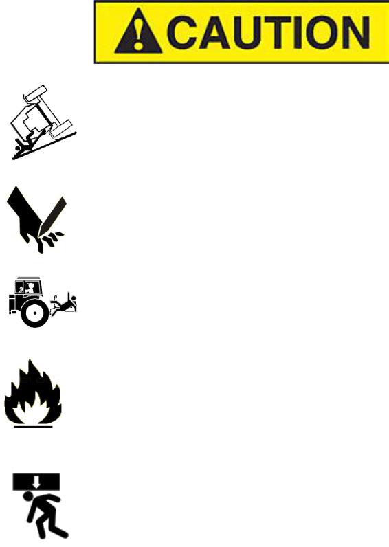
Important! Read the following SAFETY PROCEDURES before operating the Veris system:
•Read and understand all instructions on safety decals
•Escaping fluid under pressure can penetrate the skin causing serious injury. Avoid the hazard by relieving pressure before disconnecting hydraulic lines. Use a piece of paper or card-board, NOT BODY PARTS, to check for suspected leaks.
•Wear protective gloves and safety glasses or goggles when working with hydraulic and highpressure wash systems.
•If an accident occurs, see a doctor immediately. Any fluid injected into the skin must be surgically removed within a few hours or gangrene may result.
•Pinch point hazard: to prevent injury, stand clear when raising or lowering any part of the Veris implement.
•Install all transport locks before transporting or working underneath.
•Detach and store implements in an area where children normally do not play. Secure implement by using blocks and supports.
•Read Operations Manual before operating machine
•Review safety instructions with operators before operating machine and at least annually
•Never stand on or use tire as a step
•Do not tow the implement on public roads without the road-kit light package, or without the proper safety equipment and licensing as required by your State Department of Transportation. Always use safety chain.
•Riders obstruct the operator’s view. They could be struck by foreign objects or thrown from the machine.
•Never allow children to operate equipment.
•To prevent possible electrical shock, or damage to the instrument, do not connect to any power source greater than twelve (12) volts DC.
•Do not grease or oil implement while it is in operation.
•Disk edges are sharp. Be careful when working in this area.
•Disconnect battery ground cable (-) before servicing or adjusting electrical systems or before welding on implement.
•Remove buildup of mud, oil or debris.
•Be very careful when mapping stubble fields with a gasoline engine pickup. Be prepared if a fire starts.
•Keep a first aid kit and fire extinguisher handy.
1-3
Pub. # OM17-EC
Excess speed, especially when turning could cause overturning.
Never pull units faster than 15 km/hr.
Use caution when working on implement. Coulter disks are sharp and may causes cuts.
Don’t allow anyone to climb or ride on implement
The vehicle that pulls the Veris unit thru the field will get hot! There is a chance that this heat can cause field fires in stubble fields.
Don’t lower unit while any part of body is underneath
1-4

Pub. # OM17-EC
Keep safety chain installed
Install jack before unhitching; do not drop unit on foot
FCC NOTE
This equipment has been tested and found to comply with the limits for a Class A digital device, pursuant to Part 15 of the FCC Rules. These limits are designed to provide reasonable protection against harmful interference when the equipment is operated in a commercial environment. This equipment generates, uses, and can radiate radio frequency energy and, if not installed and used in accordance with the instruction manual, may cause harmful interference to radio communications. Operation of the equipment in a residential area is likely to cause harmful interference in which case the user will be required to correct the interference at this own expense.
1-5

Pub. # OM17-EC
EUROPEAN DECLARATION OF CONFORMITY
Veris Technologies, Inc., located at 601 N. Broadway in Salina Kansas, certifies that the product:
Veris 2000XA
is in conformity with the following directive and standards: Machinery Directive 2006/42/EC--1st Edition—December 2009 Electromagnetic Compatibility 2004/108/EC —December 2004
EN55022 – Measuring Radiated Emissions
The Technical File is maintained at:
Veris Technologies, Inc.
601 N. Broadway
Salina KS 67401
Date of issue: July 9, 2010
Place of issue: Salina KS USA
1-6

Pub. # OM17-EC
EUROPEAN DECLARATION OF CONFORMITY
Veris Technologies, Inc., located at 601 N. Broadway in Salina Kansas, certifies that the product:
Veris 3150
is in conformity with the following directive and standards: Machinery Directive 2006/42/EC--1st Edition—December 2009 Electromagnetic Compatibility 2004/108/EC —December 2004
EN55022 – Measuring Radiated Emissions
The Technical File is maintained at:
Veris Technologies, Inc.
601 N. Broadway
Salina KS 67401
Date of issue: April 11, 2012
Place of issue: Salina KS USA
1-7
Pub. # OM17-EC
Statement of Use
Intended use of the Veris 2000XA
The Veris 2000XA Soil EC Mapping System collects geo-referenced soil electrical conductivity (EC) measurements as it is pulled across a field by a tractor or an ATV/Quad bike. An electronic device called the Soil EC Surveyor, powered by vehicle’s 12V DC electrical system, generates a small electrical current, which is transferred into the soil through a pair of rolling electrode coulter disks. A second pair of disks measures the drop in voltage which is proportional to the electrical conductivity of soil medium at a given location. Signal response is due primarily to soil texture/grain size and soil salinity. Clay soils and soils with high salinity levels are highly conductive, while coarser soils such as sand do not conduct well. Additional weight may need to be added to the system to insure coulter disks penetrate the soil. Veris Technologies offers weights designed to mount properly to the system. The system records the data either on its own datalogger, or on a data recording device such as a laptop computer. Ultimately, the data are displayed in a map format, and variable applications of crop production materials, such as seed, fertilizer and other inputs are variably applied to the EC zones delineated on the maps. The 2000XA implement includes a set of wheels which allow it to be raised to cross ditches, irrigation canals, and for loading onto a trailer for road transport. The system is not intended to be transported on its wheels at speeds greater than 15 km/hr. Under no circumstances is the 2000XA to be transported on the road or highway behind a car or truck, as overturning may occur. The 2000XA system is designed for use in a farm field, and has no dynamic movement unless vehicle is pulling it, so guarding around soil engaging components is not needed and would interfere with field operations. Unit should not be operated when people are present in the field, as coulter disks are sharp and could cause injury if contact occurs.
Misuse of the Veris 2000XA model
Misuses of the 2000XA model include operation with people in area, and pulling the system at an excessive speed. In field position, this could result in poor data collection and possible overturning at extremely high speeds and sharp turns. In raised position, the chance of overturning is increased, as the center of gravity is higher, so care must be taken to keep speeds under 15 km/hr, and less when turning. Other possible misuses include installation of non-factory specified weights, which may overload the system or lead to additional risk of overturning.
Abnormal use of the Veris 2000XA model
Abnormal use of the 2000XA model includes using it as a cart for carrying equipment, tools, or people. Under no circumstances should anyone ride on the implement. Even though the implement is similar in appearance to a tillage tool, such as a disk harrow, it was not designed for that usage and should never be used for any purpose other than soil EC data collection.
1-8
Pub. # OM17-EC
Statement of Use
Intended use of the Veris 3150
The Veris 3150 Soil EC Mapping System collects geo-referenced soil electrical conductivity (EC) measurements as it is pulled across a field by a tractor or an pickup truck. An electronic device called the Soil EC Surveyor, powered by vehicle’s 12V DC electrical system, generates a small electrical current, which is transferred into the soil through a pair of rolling electrode coulter disks. A second pair of disks measures the drop in voltage which is proportional to the electrical conductivity of soil medium at a given location. Signal response is due primarily to soil texture/grain size and soil salinity. Clay soils and soils with high salinity levels are highly conductive, while coarser soils such as sand do not conduct well. Additional weight may need to be added to the system to insure coulter disks penetrate the soil. Veris Technologies offers weights designed to mount properly to the system. The system records the data either on its own datalogger, or on a data recording device such as a laptop computer. Ultimately, the data are displayed in a map format, and variable applications of crop production materials, such as seed, fertilizer and other inputs are variably applied to the EC zones delineated on the maps. The 3150 implement includes a set of wheels which allow it to be raised to cross ditches, irrigation canals, and for loading onto a trailer for road transport. The 3150 system is designed for use in a farm field, and has no dynamic movement unless vehicle is pulling it, so guarding around soil engaging components is not needed and would interfere with field operations. When equipped with road lights and road kit 3150 implement can be safely towed at speeds up to 80km/hr depending on road conditions. Legal road transportation depends on country, state and municipal regulations. Unit should not be operated when people are present in the field, as coulter disks are sharp and could cause injury if contact occurs.
Misuse of the Veris 3150 model
Misuses of the 3150 model include operation with people in area, and pulling the system at an excessive speed. In field position, this could result in poor data collection and possible overturning at extremely high speeds and sharp turns. In raised position, the chance of overturning is increased, as the center of gravity is higher, so care must be taken to keep speeds under 15 km/hr, and less when turning. Other possible misuses include installation of non-factory specified weights, which may overload the system or lead to additional risk of overturning.
Abnormal use of the Veris 3150 model
Abnormal use of the 3150 model includes using it as a cart for carrying equipment, tools, or people. Under no circumstances should anyone ride on the implement. Even though the implement is similar in appearance to a tillage tool, such as a disk harrow, it was not designed for that usage and should never be used for any purpose other than soil EC data collection.
1-9
Pub. # OM17-EC
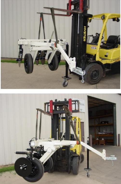
2000XA Lifting Points
Below are the recommended lifting points for the unit. Using two straps you can safely lift the unit. Make sure the straps used to lift are rated greater than 1200 lbs. Fork extensions maybe required to lift. Always stay clear when lifting the unit.
1-10
Pub. # OM17-EC
1-11

Pub. # OM17-EC
3150 Lifting Points
Below are the recommended lifting points for the unit. Using two straps you can safely lift the unit. Make sure the straps used to lift are rated greater than 1200 lbs. Fork extensions maybe required to lift. Always stay clear when lifting the unit.
1-12

Pub. # OM17-EC
Section 2
Electronics Overview and Set-up
The Veris Electronics kits includes the following items:
Protective |
EC |
Data- |
|
|
case |
Logger |
SD |
||
Surveyor |
||||
|
|
|||
|
|
card |
||
Serial |
|
|
||
|
|
reader |
||
cable |
|
|
||
|
|
|
||
Signal test |
SoilViewer |
|
|
|
box |
software |
|
|
|
|
Mtg |
|
Mtg |
|
|
bracket |
|
bracket |
|
Signal test |
|
Power |
|
|
load |
|
cord |
|
|
|
Power cord |
|
|
|
Figure 1. EC Surveyor kit |
|
|
Figure 2. DataLogger kit |
Use protective shipping/storage case to protect electronics components whenever electronics are shipped. Keep all diagnostics and operations manual with system when mapping.
Mount instrument in a location that is as free as possible from dust, vibration, and electrical interference. Display should be visible to operator and shielded from direct sunlight. Use adjustable mounting brackets to position electronics for optimal visibility (Figure 3).
Figure 3.
2-1

Pub. # OM17-EC
Figure 4. EC Surveyor (rear)
Power port:
The Soil EC Surveyor is shipped with an accessory power cord. If an alternative connection is desired, make sure that the unit
is properly connected to a power connection that is not controlled by the ignition switch. If connecting directly to the battery, we suggest a 3-amp inline fuse is installed between the battery and the instrument.
EC Signal: |
EC Data out: |
GPS input: |
EC Signal Cable |
Attach serial cable |
Connect GPS cable here. |
extension from |
here and other end |
It is designed to accept |
implement attaches |
to Sensor |
GPS input in NMEA 0183 |
to the EC Surveyor |
DataLogger or |
format via an RS232 |
here. Route cable |
laptop PC. |
connector. |
properly to prevent |
|
(GPS must send GGA and |
damage. Signal test |
|
either VTG or RMC strings |
load also attaches |
|
at a 1hz rate, at 4800 baud, |
|
||
here—used to test |
|
8 data bits, 1 stop bit, no |
EC Surveyor. |
|
parity.) |
Figure 5. EC Surveyor (front)
Fuse:
This allows the fuse to be replaced, with a 1A fastblow fuse, if blown.
Data Status: |
Power: |
On/Off: |
|
When lit, this green LED |
When lit, this red |
||
Turns power to EC |
|||
indicates data is being sent |
LED indicates EC |
||
Surveyor on and |
|||
out serial port. If not lit, EC |
Surveyor is powered |
||
off. |
|||
values are negative or GPS |
up. |
||
|
|||
signal not received. |
|
|
Figure 6. DataLogger (rear)
2-2

Reset |
|
|
|
EC: |
|
button: |
|
|
|
Serial cable |
|
Can be used |
|
|
|
from EC |
|
to reboot |
|
|
|
Surveyor |
|
DataLogger |
|
|
|
attaches here. |
|
|
|
|
|
|
|
Alarm Vol: |
|
|
|
||
Used to adjust |
|
|
volume of auditory |
|
|
alarm |
|
|
pH:
Serial cable from pH Controller (MSP only) attaches here.
Pub. # OM17-EC
Power port:
The Sensor DataLogger is shipped with an accessory power cord. If an alternative connection is desired, make sure that the unit is properly connected to a power connection that is not controlled by the ignition switch. If connecting directly to the battery, we suggest a 3-amp in-line fuse is installed between the battery and the instrument.
Figure 7. DataLogger (front)
Memory Card slot:
Formatted SD memory card must be installed when booting up, and at all times data is being collected. See Proc. #6 for formatting instructions.
Data Status: |
|
|
When lit, this green |
Power: |
On/Off: |
LED indicates data |
When lit, this red |
Turns power to |
is being recorded to |
LED indicates |
Sensor DataLogger |
memory card. If not |
Sensor DataLogger |
on and off. |
lit, EC values are |
is powered up. |
Fuse: |
negative or GPS |
This allows the fuse |
|
to be replaced, with |
||
signal not received. |
||
a 500mA Fastblow |
||
|
||
|
fuse, if blown. |
2-3

Pub. # OM17-EC
Important – Do not allow moisture to enter the Soil EC Surveyor or Sensor DataLogger, and do not pass strong magnets near the unit.
Software Setup
The Veris SoilViewer software will automatically run the setup once the CD is inserted into the computer. If not the installation can be manually started by double clicking on the setup.exe located on the CD.
|
Click Next to continue through |
Figure 8. |
installation |
|
Once the CD has begun select the installation directory and click Next
Figure 9.
2-4

Pub. # OM17-EC
Next two license agreements will need to be accepted before continuing.
Figures 10a and 10b.
The installer will install all necessary components
Figure 11.
Once the installer is completed, click finish
Figure 5
2-5

Pub. # OM17-EC
The Veris SoilViewer will now install drivers necessary to operate the included USBSerial Converter (part #41377). If you do not want to use the included converter than press cancel here, otherwise click next. If you have the USBSerial converter plugged in be sure to unplug it before clicking next.
After the drivers are successfully installed click finish and Restart your computer before opening Veris SoilViewer.
Figure 6
Once the computer is restarted the USB to
Serial converter cable can be plugged in,
Windows will recognize the new hardware.
Figure 7
Windows will then advice the new hardware is installed and ready to use.
Figure 8
2-6
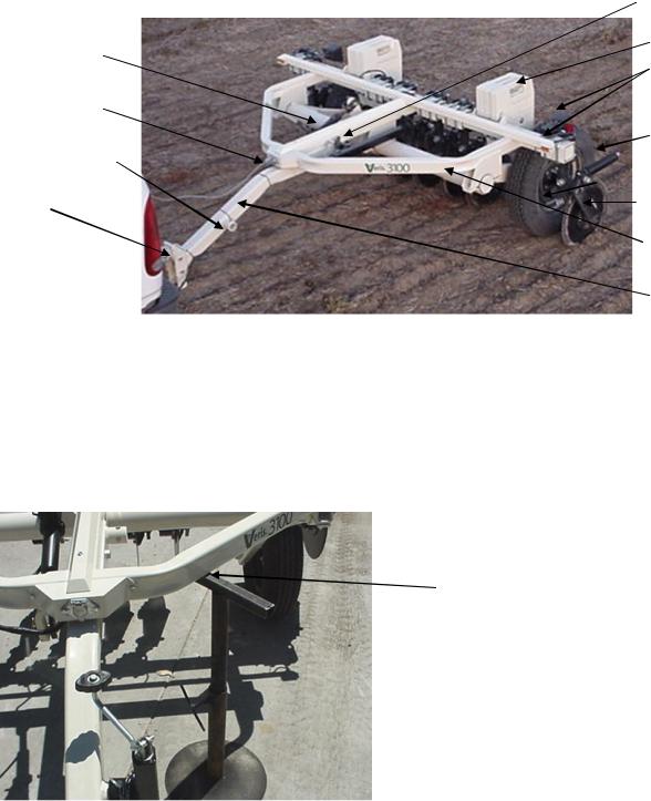
Ratchet for raising/lowering
Signal Cable quickconnect coupler port
Jack location for implement storage
Implement hitch (2” ball)
Figure 1.
Section 3
Implement Overview and Set-up (3100 shown)
Pub. # OM17-EC
Jack location for field operation
Weights
Road kit: stop, turn, and clearance lights
4-bolt hubs and P205
R75 highway tires
Coulter electrodes
Rockshaft and frame
Tongue
If the unit is crated, the tongue must be installed prior to use. To do so, please take precautions to ensure that the framework is properly supported to ensure safety.
1)Remove bands that attach tongue and framework to shipping pallet.
2)Use a forklift or small loader to raise front portion of tongue into level position and properly support with a sawhorse or other support of your choice.
Support here
Figure 2.
3-1
 Loading...