

Page 1

Operations & Maintenance Manual EN
Manuel d'utilisation et de maintenance
Bedienungs‑ und Wartungshandbuch
Manual de funcionamiento y mantenimiento
Manuale di funzionamento e manutenzione
Manual de Manutenção e Operações
Betjenings‑ og vedligeholdelsesvejledning DA
Bedienings‑ en onderhoudshandleiding NL
Drifts‑ og vedlikeholdshåndbok
Drift‑ och underhållshandbok
0900‑4788‑05‑60
FR
DE
ES
IT
PT
NO
SV
Page 2

Page 3

EN
ENGLISH ..................................................................................................................... 1
Important Information ................................................................................................. 1
Introduction................................................................................................................. 4
Setting Up the System ................................................................................................. 6
Using the Device ........................................................................................................ 10
Cleaning & Disinfecting ............................................................................................. 13
Maintenance & Safety ................................................................................................ 19
Warranty ................................................................................................................... 20
Product Specifications ............................................................................................... 20
FR
FRANÇAIS ................................................................................................................ 25
Informations importantes .......................................................................................... 25
Introduction............................................................................................................... 28
Configuration du système .......................................................................................... 29
Utilisation du dispositif .............................................................................................. 31
Nettoyage et désinfection .......................................................................................... 33
Maintenance et sécurité ............................................................................................. 36
Garantie .................................................................................................................... 38
Caractéristiques du produit ........................................................................................ 38
DE
DEUTSCH .................................................................................................................. 44
Wichtige Informationen .............................................................................................44
Einführung ................................................................................................................. 47
Einrichten des Systems ............................................................................................... 48
Verwenden des Geräts .............................................................................................. 51
Reinigung und Desinfektion ....................................................................................... 53
Wartung und Sicherheit ............................................................................................. 56
Garantie .................................................................................................................... 57
Technische Produktdaten ........................................................................................... 57
ES
ESPAÑOL .................................................................................................................. 63
Información importante ............................................................................................. 63
Introducción .............................................................................................................. 66
Configuración del sistema .......................................................................................... 67
Uso del dispositivo ..................................................................................................... 69
Limpieza y desinfección ............................................................................................. 71
Mantenimiento y seguridad ....................................................................................... 75
Garantía .................................................................................................................... 76
Especificaciones del producto .................................................................................... 76
i
Page 4

IT
ITALIANO .................................................................................................................81
Informazioni importanti ............................................................................................. 81
Introduzione .............................................................................................................. 84
Configurazione del sistema ........................................................................................ 85
Utilizzo del dispositivo ............................................................................................... 87
Pulizia e disinfezione .................................................................................................. 89
Manutenzione e sicurezza ......................................................................................... 92
Garanzia .................................................................................................................... 93
Specifiche di prodotto ............................................................................................... 93
PT
PORTUGUÊS ............................................................................................................. 99
Informações importantes ........................................................................................... 99
Introdução ............................................................................................................... 102
Configuração do sistema ......................................................................................... 103
Utilizar o dispositivo ................................................................................................. 105
Limpeza e desinfeção .............................................................................................. 107
Manutenção e segurança .........................................................................................11 0
Garantia ...................................................................................................................112
Especificações do produto ........................................................................................112
DA
DANSK .....................................................................................................................117
Vigtig information ....................................................................................................117
Indledning ............................................................................................................... 120
Indstilling af systemet ...............................................................................................121
Brug af enheden ...................................................................................................... 123
Rengøring og desinfektion....................................................................................... 125
Vedligeholdelse og sikkerhed ....................................................................................127
Garanti .................................................................................................................... 129
Produktspecifikationer ............................................................................................. 129
NL
NEDERLANDS ......................................................................................................... 134
Belangrijke informatie .............................................................................................. 13 4
Inleiding................................................................................................................... 137
Het systeem opstellen .............................................................................................. 13 8
Het apparaat gebruiken ............................................................................................141
Reinigen en desinfecteren ........................................................................................ 143
Onderhoud en veiligheid ......................................................................................... 146
Garantie .................................................................................................................. 147
Productspecificaties ................................................................................................. 14 8
ii
Page 5

NO
NORSK .................................................................................................................... 154
Viktig informasjon ................................................................................................... 154
Innledning ............................................................................................................... 157
Oppsett av systemet ................................................................................................ 15 8
Bruke enheten ......................................................................................................... 160
Rengjøring og desinfeksjon...................................................................................... 162
Vedlikehold og sikkerhet .......................................................................................... 164
Garanti .................................................................................................................... 166
Produktspesifikasjoner ............................................................................................. 166
SV
SVENSKA ................................................................................................................ 171
Viktig information.....................................................................................................171
Inledning ..................................................................................................................174
Installera systemet ................................................................................................... 175
Använda enheten .................................................................................................... 17 7
Rengöring och desinficering .................................................................................... 179
Underhåll och säkerhet ............................................................................................ 182
Garanti .................................................................................................................... 183
Produktspecifikationer ............................................................................................. 183
iii
Page 6

Page 7

EN
ENGLISH
IMPORTANT INFORMATION
CONTACT INFORMATION
To obtain additional information regarding your system, please contact Verathon®
Customer Care or visit verathon.com/support.
Headquarters European Rep Manufacturer
Verathon Inc.
20001 Nor th Creek Parkway
Bothell, WA 98011 U.S.A.
Tel: +1 800 331 2313 (US/Canada)
Tel: +1 425 867 1348
Fax: +1 425 883 2896
ABOUT THIS MANUAL
Information in this manual may change at any time without notice. For the most up‑to‑date
information, see the documentation available at verathon.com/product‑documentation.
Copyright © 2018 by Verathon Inc. All rights reserved. No part of this manual may be
copied or transmitted by any method without the express written consent of Verathon Inc.
Ambient Light Reduction, DirectView, Dynamic Light Control, GlideRite, GlideScope,
GlideScope Go, the GlideScope symbol, Spectrum, Verathon, and the Verathon Torch
symbol are trademarks or registered trademarks of Verathon Inc. All other brand and
product names are trademarks or registered trademarks of their respective owners.
Verathon Medical (Europe) B.V.
Willem Fenengastraat 13
1096 BL Amsterdam
The Netherlands
Tel: +31 (0) 20 210 30 91
Fax : +31 (0) 20 210 30 92
Verathon Medical (Canada) ULC
2227 Douglas Road
Burnaby, BC V5C 5A9
Canada
Tel: +1 604 439 3009
Fax: +1 604 439 3039
PRODUCT DESCRIPTION
GlideScope Go is a handheld video laryngoscope system designed to deliver clear airway
views, both directly and indirectly, facilitating rapid intubation. The reusable 3.5‑inch tilting
color monitor and rechargeable battery can be fully submerged for cleaning. Available
user settings include auto‑record, auto‑shutdown, and content display, supporting a more
customized user experience. This system integrates with the Spectrum™ product portfolio
offering fully disposable blades that can be swapped without powering down the monitor.
It also integrates with the GlideScope Video Baton 2.0, which reduces electronic waste
through the use of disposable Stats. GlideScope Go is ideal for working under rugged
conditions, for routine and difficult airways, and in a wide range of patients and clinical
settings.
STATEMENT OF INTENDED USE
The GlideScope Go System is intended for use by qualified medical professionals to obtain
a clear, unobstructed view of the airway and vocal cords for medical procedures.
STATEMENT OF PRESCRIPTION
Federal (United States) law restricts this device to sale by, or on the order of, a physician.
1
Page 8

NOTICE TO ALL USERS
The system should be used only by individuals who have been trained and authorized
by a physician, or by health care providers who have been trained and authorized by the
institution providing patient care. Verathon® recommends that all users do the following:
• Read the manual before using the instrument
• Obtain instruction from a qualified individual
• Practice using the video laryngoscope on a mannequin before clinical use
• Acquire clinical training experience on patients without airway abnormalities
CAUTIONS & WARNINGS
Warnings indicate that injury, death, or other serious adverse reactions may result from
use or misuse of the device. Cautions indicate that use or misuse of the device may
cause a problem, such as a malfunction, failure, or damage to the product. Throughout
the manual, pay attention to sections labeled Important, as these contain reminders or
summaries of the following cautions as they apply to a specific component or usesituation.
Please heed the following warnings and cautions.
CAUTION
regarding electromagnetic compatibility (EMC) and must be installed and operated
according to the instructions in this manual. For more information, see the Electromagnetic
Compatibility section on page22.
CAUTION
video recording. Removing the USB flash drive before a recording has fully saved may corrupt
the video file.
CAUTION
using the approved low‑temperature processes recommended by Verathon.
CAUTION
a power adapter or charging cradle.
CAUTION
or disinfecting the monitor. The screen can be scratched, permanently damaging the device.
CAUTION
WARNING
WARNING
electromagnetic compatibility, use only the accessories and components recommended by
Verathon, including the provided, medical‑approved powersupply.
Medical electrical equipment requires special precautions
Disconnect the blade or turn off the monitor in order to save a
This product may only be cleaned, disinfected, or sterilized by
Ensure the monitor's micro‑USB port is dry before connecting
Ensure that you do not use any abrasive tools when cleaning
Do not submerge the charging cradle in a liquid solution.
The monitor must be cleaned before initial use.
To reduce the risk of electrical shock and maintain
WARNING
of the video laryngoscope, ensure that you are looking in the patient’s mouth, not at the
screen. Failure to do so may result in injury, such as to the tonsils or soft palate.
When you are guiding the endotracheal tube to the distal tip
2
Page 9

WARNING
handling and disposing of cleaning, disinfection, or sterilization solutions.
Ensure that you follow the manufacturer’s instructions for
WARNING
Reuse, reprocessing, or resterilization may create a risk of contamination of thedevice.
WARNING
WARNING
cause serious injury to the operator or damage to the instrument and will void the warranty.
Contact Verathon® Customer Care for all servicing needs.
WARNING
can contact the patient and can exceed 41°C (106°F) as part of normal operation. Patient
contact with this area of the blade during intubation is unlikely, as it would cause an
obstruction of the camera view. Do not maintain continuous contact with this area of the
blade for longer than 1minute; it is possible to cause thermal damage such as a burn to the
mucosal tissue.
WARNING
are not compatible with this system:
• 0574‑0176 (Spectrum™ LoPro S3) • 0574‑0178 (Spectrum MAC S3)
• 0574‑0177 (Spectrum LoPro S4) • 0574‑0179 (Spectrum MAC S4)
Refer to part numbers when assessing whether a blade is compatible with the system. For
more information about compatible components and accessories, see page5.
WARNING
or body fluids capable of transmitting pathogens, all cleaning facilities must be in compliance
with (U.S.) OSHA Standard 29 CFR1910.1030 “Bloodborne Pathogens” or an equivalent
standard. For more information, visit www.osha.gov.
Do not reuse, reprocess, or resterilize single‑use components.
No modification of this equipment is allowed.
Do not attempt to open the system components. This may
The area surrounding the camera in the video laryngoscope
GlideScope blades labeled with the following part numbers
Because the product may be contaminated with human blood
WARNING
and has no sign of damage. Do not use this product if the device appears damaged. Ensure
that alternative airway management methods and equipment are available.
WARNING
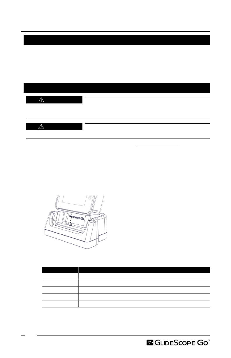
placing it in the charging cradle.
WARNING
GlideScope Go monitor.
Before every use, ensure the instrument is operating correctly
Ensure the monitor is clean and free of contamination before
The charging cradle should be used only for charging the
SYMBOLS
For a full list of caution, warning, and informational symbols used on this and other Verathon
products, please refer to the Verathon Symbol Directory at verathon.com/symbols.
3
Page 10

INTRODUCTION
SYSTEM OVERVIEW
The GlideScope Go system features a small handheld monitor that can use either
GlideScope Spectrum video laryngoscopes or GlideScope GVL® Stats.
GlideScope Spectrum video laryngoscopes are durable, single‑use plastic blades that must
be disposed of after one use. Single‑use blades are identified by an S in their name, such as
LoPro S4. These blades incorporate the following technologies:
• Dynamic Light Control™—Optimizes image brightness and clarity.
• Ambient Light Reduction™— Diminishes excess reflected light to further improve
image quality.
GVL Stats are durable, transparent, single‑use laryngoscope shells that fit over a flexible,
reusable stalk called a video baton. The Stats contain no active components, so waste is
kept to a minimum. Although they are single‑use devices, they do not have an S in their
names.
Figure 1. GlideScope Go Monitor
Indicator LED
Micro‑USB and
charging port
Power button
Connector arm
Blade/baton connector
4
LCD screen
Page 11

SYSTEM PARTS & ACCESSORIES
REQUIRED SYSTEM COMPONENTS
The following components are required for the system to function:
• GlideScope Go monitor
• Power adapter
INTERCHANGEABLE COMPONENTS
The system also must have one video laryngoscope connected to function. The
laryngoscope can be either a Spectrum™ blade or a video baton with a Stat, as shown in
the following list:
• Spectrum LoPro S1 (0574‑0165)
• Spectrum LoPro S2 (0574‑0166)
• Spectrum LoPro S3 (0574‑0194)
• Spectrum LoPro S4 (0574‑0195)
• Spectrum DirectView™ MAC S3 (0574‑0187)
• Spectrum DirectView MAC S4 (0574‑0188)
• GlideScope Video Baton 2.0, Large (size 3‑4, part number 0570‑0382) with one of
the following:
GVL® 3 Stat (0270‑ 0626)
GVL® 4 Stat (0270‑ 0628)
ADDITIONAL ACCESSORIES
The following accessories are optional and may be used with the system:
• Charging cradle
• Small carrying case
• Large carrying case
• GlideRite® Rigid Stylet (For ET tubes 6.0 mm or larger)
• GlideRite Single‑Use Stylet – Small (For ET tubes 3.0–4.0 mm)
• Micro‑to‑standard hybrid USB flash drive, for configuring settings and recording video
5
Page 12
SETTING UP THE SYSTEM
PROCEDURE 1. PERFORM INITIAL INSPECTION
1. Verify that you have received the appropriate components for your system by
referring to the packing list included with the system.
2. Inspect the components for damage.
3. If any of the components are missing or damaged, notify the carrier and Verathon®
Customer Care or your local representative.
PROCEDURE 2. CHARGE THE BATTERY
WARNING
electromagnetic compatibility, use only the accessories and components recommended by
Verathon, including the provided, medical‑approved powersupply.
WARNING
placing in the charging cradle.
For more about the battery and charging conditions, see Battery Specifications on page21.
1. Connect the power adapter to a hospital‑grade power outlet.
2. Ensure the micro‑USB port on the monitor is dry.
3. If charging directly from the power adapter, connect it to the micro‑USB port on
the monitor.
If charging with the charging cradle, connect the power adapter to the micro‑USB
port on the cradle, and then place the monitor in the cradle.
See the following table for a list of indicator LED status descriptions.
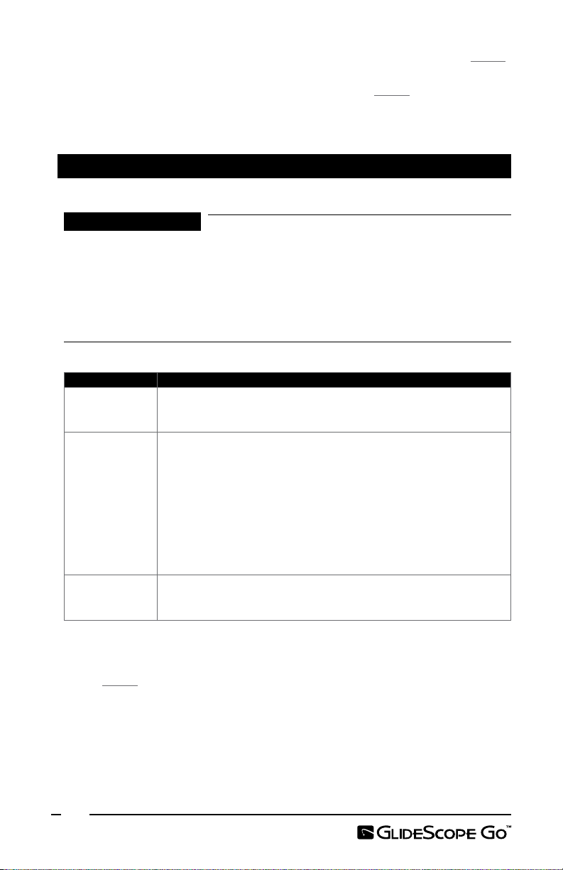
Table 1. Indicator LED Status Descriptions
LED Status Description
Solid green Battery is fully charged.
Solid orange Battery is charging with an approved or equivalent power adapter.
Solid red Battery is charging with an unapproved power adapter.
Blinking red Error. There is a problem with the battery or charging circuit.
Off Not charging.
* Using an unapproved power adapter may not charge the battery correctly. Please replace the unapproved
power adapter with the power adapter provided with the system.
To reduce the risk of electrical shock and maintain
Ensure the monitor is clean and free of contamination before
*
6
Page 13
4. Allow the battery to charge until the indicator LED is solid green.
5. Remove the monitor from the cradle, and then press the Power button on the
monitor.
Note: Do not attach a blade or baton at this time.
6. In the upper right corner of the monitor screen, verify that the installed software
version is 1.3 or higher. If not, contact Verathon® Customer Care for a software
update.
PROCEDURE 3. CONFIGURE USER SETTINGS
The User Settings Tool is a Java‑based tool and is available on the USB flash drive.
1. Connect the USB flash drive to a USB port on a computer.
2. Navigate to the USB flash drive, and then open the User Settings Tool.
3. Configure the settings as needed, and then click Save.
4. In the Save As dialog box, navigate to the USB flash drive, and then click Save.
5. Ensure the monitor is powered off, and then insert the USB flash drive into the
micro‑USB port on the monitor.
6. On the monitor, press the Power button. The monitor powers on and the settings
automatically update. The settings file is then automatically deleted to help prevent
accidentally overwriting the date and time settings.
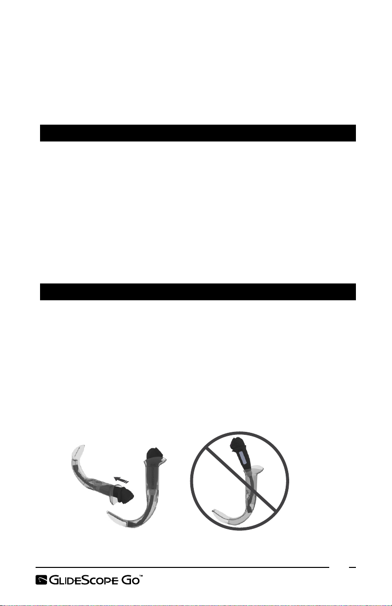
PROCEDURE 4. INSERT THE VIDEO BATON INTO THE STAT (OPTIONAL)
If you are using a video baton and a GVL® Stat, attach the Stat to the baton before you
connect the baton to the monitor.
1. Open the GVL Stat pouch, but do not remove the Stat from the packaging.
2. Ensure that the logo on the side of the baton and the logo on the side of the Stat
are aligned.
3. Slide the video baton into the GVL Stat until it clicks into place. Do not remove the
Stat from the pouch until you are ready to begin the intubation. This ensures that
the Stat remains as clean as possible.
Note: Ensure that you do not insert the video baton backwards.
Correct Incorrect
7
Page 14

4. When you remove the GVL® Stat from the packaging, visually inspect the Stat to
ensure that all exterior surfaces are free of unintended rough areas, sharp edges,
protrusions, or cracks.
5. If desired to provide additional anti‑fog benefits, you may apply Dexide™ Fred™
Lite to the camera window on the Stat.* Use the solution according to the
manufacturer’s instructions.
PROCEDURE 5. ATTACH THE BLADE OR BATON
The blade or video baton attaches to the monitor’s connector arm. The monitor rotates on
the connector arm, allowing you to set a starting angle to begin the intubation.
It is recommended that you leave the sterile, single‑use blade in the packaging while
connecting the blade and until you are ready to perform an intubation procedure.
1. Align the arrow on the monitor with the arrow on the baton or single‑use blade,
and then insert the blade/baton connector fully into the connector port on the
blade or baton.
Alignment marks
* Compatibility has been demonstrated for up to one hour of continuous exposure on video batons and Stats.
8
Page 15

PROCEDURE 6. PERFORM A FUNCTIONAL CHECK
Before you use the device for the first time, ensure the system is working properly.
1. Fully charge the monitor battery.
2. Attach the video laryngoscope to the monitor, according to the prior procedure.
3. Press the Power button. The monitor turns on.
4. Look at the screen, and verify that video is being received from the laryngoscope.
Note: The edges of the blade or Stat may be captured in the camera view. This
image acts as a frame of reference during the intubation process and ensures that
the orientation of the image is correct in the monitor.
9
Page 16

USING THE DEVICE
Prior to using the device, complete the instructions in the chapter Setting Up the System.
PROCEDURE 1. PREPARE THE SYSTEM
WARNING
are not compatible with this system:
• 0574‑0176 (Spectrum™ LoPro S3) • 0574‑0178 (Spectrum MAC S3)
• 0574‑0177 (Spectrum LoPro S4) • 0574‑0179 (Spectrum MAC S4)
Refer to part numbers when assessing whether a blade is compatible with the system. For
more information about compatible components and accessories, see page5.
WARNING
and has no sign of damage. Do not use this product if the device appears damaged. Ensure
that alternative airway management methods and equipment are available.
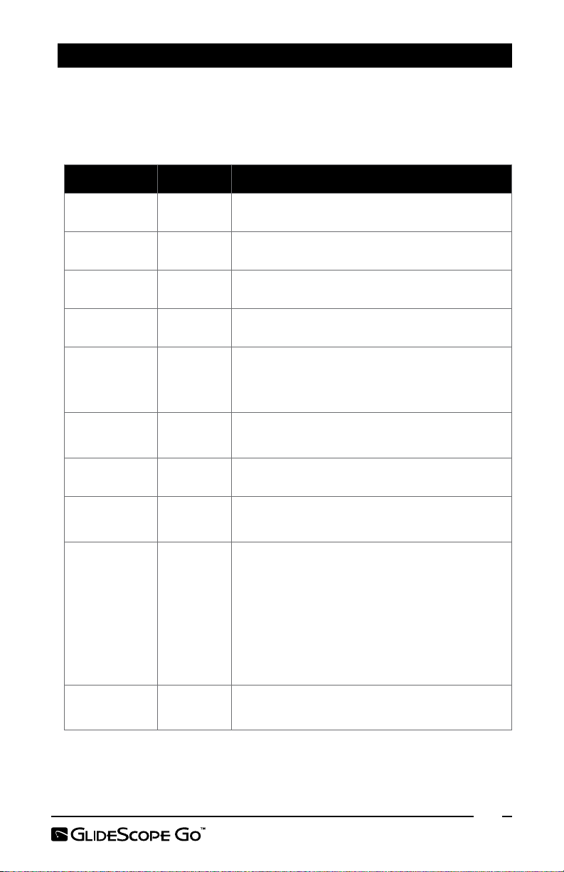
Table 2. Video Laryngoscope Sizes
GlideScope Blade Part Number Recommended Patient Weight/Size
Spectrum™ LoPro S1 0574‑ 0165 1.5–3.8kg (3.3–8.4lbs)
Spectrum LoPro S2 0574‑016 6 1.8–10kg (4–22lbs)
Spectrum LoPro S3 0574‑019 4 10kg (22lbs) to medium adult
Spectrum LoPro S4 0574‑ 0195 40kg (88lbs) to large adult
GVL® 3 Stat 0270‑ 0626 Medium adult
GVL® 4 Stat 0270‑0628 Large adult
Spectrum DirectView™ MAC S3 0574 ‑ 0187 Medium adult
Spectrum DirectView MAC S4 0574‑ 0188 Large adult
1. Ensure that each GlideScope system component has been properly cleaned or
disinfected according to the guidance provided in Tabl e 3 on page13.
2. Using the information in Table 2, in combination with a clinical assessment of the
patient and the experience and judgment of the clinician, select the GlideScope
video laryngoscope that is appropriate for the patient.
3. Attach the video laryngoscope to the monitor per Attach the Blade or Baton on
page8.
GlideScope blades labeled with the following part numbers
Before every use, ensure the instrument is operating correctly
*
* Weight ranges are approximate; a medical professional must evaluate on a patient‑by‑ patient basis.
10
Page 17
PROCEDURE 2. PERFORM AN INTUBATION
WARNING
can contact the patient and can exceed 41°C (106°F) as part of normal operation. Patient
contact with this area of the blade during intubation is unlikely, as it would cause an
obstruction of the camera view. Do not maintain continuous contact with this area of the
blade for longer than 1minute; it is possible to cause thermal damage such as a burn to the
mucosal tissue.
WARNING
of the video laryngoscope, ensure that you are looking in the patient’s mouth, not at the
screen. Failure to do so may result in injury, such as to the tonsils or soft palate.
To perform an intubation, Verathon® recommends using the GlideScope 4‑Step Technique
as outlined in this procedure. Each step begins with where the user should be looking to
complete that action. Prior to beginning this procedure, verify that the monitor is receiving
an accurate image from the video laryngoscope.
1. Look in the Mouth: With the video laryngoscope in your left hand, introduce it
along the midline of the oropharynx.
2. Look at the Screen: Identify the epiglottis, and then manipulate the blade in
order to obtain the best glottic view.
3. Look in the Mouth: Carefully guide the distal tip of the tube into position towards
the tip of the laryngoscope.
4. Look at the Screen: Complete the intubation, gently rotating or angling the tube as
needed to redirectit.
The area surrounding the camera in the video laryngoscope
When you are guiding the endotracheal tube to the distal tip
PROCEDURE 3. RECORD THE INTUBATION
CAUTION
video recording. Removing the USB flash drive before a recording has fully saved may corrupt
the video file.
1. Start the recording by ensuring the following conditions are met:
• A blade or video baton is connected to the monitor.
• A USB flash drive is connected to the micro‑USB port on the monitor.
• The monitor is powered on.
• The record feature is turned on in the user settings.
Once these conditions are met, the recording starts automatically.
2. Stop the recording by pressing and holding the power button until the monitor
has fully powered off. The recording also stops when the video laryngoscope is
disconnected, the media capacity on the USB flash drive drops too low, or the
monitor’s remaining battery charge provides less than 1minute of power.
3. If you would like to review the recording, connect the USB flash drive to a computer,
and then view the .avi file. Files are automatically named with the system date and
time.
Disconnect the blade or turn off the monitor in order to save a
11
Page 18

PROCEDURE 4. DISCONNECT THE BATON (VIDEO BATONS ONLY)
The GVL® Stat is a sterile, single‑use device. After each use, it is a biohazard, and it should
be removed from the video baton and disposed of in a manner consistent with local
protocols.
1. Hold the Stat in one hand.
2. To reduce the force required to remove the video baton from the Stat, use your
thumb and finger to gently press the collar of the Stat.
3. With the other hand, grasp the handle of the video baton and pull firmly.
12
Page 19
CLEANING & DISINFECTING
CAUTION
Ensure that you do not use any abrasive tools when cleaning
or disinfecting the monitor. The screen can be scratched, permanently damaging the device.
CAUTION
This product may only be cleaned, disinfected, or sterilized by
using the approved low‑temperature processes recommended by Verathon®.
WARNING
Because the product may be contaminated with human blood
or body fluids capable of transmitting pathogens, all cleaning facilities must be in compliance
with (U.S.) OSHA Standard 29 CFR1910.1030 “Bloodborne Pathogens” or an equivalent
standard. For more information, visit www.osha.gov.
WARNING
Ensure that you follow the manufacturer’s instructions for
handling and disposing of cleaning, disinfection, or sterilization solutions.
WARNING
Do not reuse, reprocess, or resterilize single‑use components.
Reuse, reprocessing, or resterilization may create a risk of contamination of thedevice.
WARNING
The monitor must be cleaned before initial use.
Single‑use blades arrive sterilized by ethylene oxide, and they do not require cleaning,
disinfection, or sterilization prior to use. Dispose of single‑use blades once they have been
used. Do not attempt to disinfect and reuse single‑use video laryngoscopes.
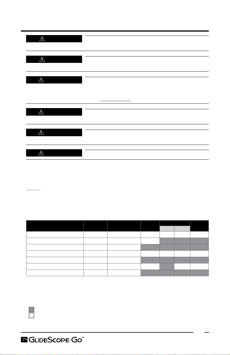
Table 3 describes the risk assessment for each system component, including the Spaulding
classification for the minimum required disinfection level. Prior to each use, ensure that
each system component has been cleaned, disinfected, or sterilized according to the
guidance provided in this table.
Table 3. System Risk Classification
Device Use
Monitor Reusable Non‑critical X
Charging cradle
Single‑use blades
Video Baton 2.0
GVL® Stats
GlideRite® RigidStylet
GlideRite Single‑Use Stylet§Single‑use —
* Clean the charging cradle whe n visibly soiled and on a regular b asis.
† For instr uctions, see the GlideRite Rigid Stylet Operations and Maintenance Manual.
§ Single‑use blades and stylets may not be reused. Dispose of single‑ use items after use.
|| Video batons require low‑level disinfection between uses, but may be high ‑level disinfected if desired.
X Checked boxes show minimum disinfection level requirement.
Shaded ar eas indicate that the disinfection or sterilization level is not required or not compatible with the device.
Unshaded areas show permissible levels of disinfe ction or sterilization based on compatibilit y with the device materials.
*
§
||
§
Reusable Non‑critical
Single‑use —
Reusable Non‑critical X
Single‑use —
†
Reusable Semi‑critical X
Spaulding
Classification
Clean
Disinfect
Low High
Sterile
13
Page 20

COMPATIBILITY & AVAILABILITY
Availability of cleaning, disinfection, and sterilization products varies by country, and
Verathon® is unable to test products in every market. Ensure that you select products
in accordance with your local laws and regulations. For information about additional
solutions that may be available, please contact Verathon Customer Care.
The following solutions have demonstrated material compatibility with the charging cradle
and monitor, and cleaning or disinfection efficacy with the monitor:
Solution Cycles
ASP® CIDEZYME® Enzymatic Detergent 15 0 0
ASP® CIDEX® OPA Disinfectant 150 0
PDI® Sani‑Cloth® AF3 Germicidal Disposable Wipe
The following solutions have demonstrated material compatibility only with the monitor
through the number of use cycles shown, but have not been tested for cleaning or
disinfection efficacy. Refer to the solution manufacturers' instructions for information
about how to use them.
Solution Cycles
Clinell® Universal Wipes 150 0
Metrex® CaviW i pes™ 150 0
Metrex® CaviWip e s1™ 150 0
Tristel Trio® Wipes System 150 0
Wip'Anios Excel Wipes 1500
150 0
PROCEDURE 1. CLEAN THE MONITOR
Clean the monitor after each use, adhering to the instructions below. Verathon has
validated the solutions and method below for compatibility and efficacy. For information
about additional solutions that may be available, please contact Verathon Customer Care.
Table 4. Cleaning Solutions for GlideScope Go
Solution Conditions
Up to 1500 cycles as per the following instructions:
Exposure: Prepare working solution at a concentration of 8–16 mL
ASP® CIDEZYME®
Enzymatic
Detergent
PDI® Sani‑Cloth®
AF3 Germicidal
Disposable Wipe
per L (1–2 U.S. fluid ounces per U.S. gallon). Soak component for
1–3 minutes. Use a lint‑free cloth or cotton‑tip swab to clean the
component while still immersed, paying special attention to the
areas around the button, hinge, all surface contours, and edges.
Rinse: Rinse for 3 minutes under running water. Ensure the HDMI
connector and micro USB connector are properly rinsed.
Up to 1500 cycles as per the following instructions:
Exposure: Use towelette(s) to remove all visible contamination from
the component. Using fresh towelette(s), wet all surfaces and allow
to remain wet for a minimum of 3 minutes. Paying special attention
to hard‑to‑reach surface contours and edges.
Rinse: N/A. Allow the component to thoroughly air dry.
14
Page 21

1. Ensure the monitor is turned off, and the power adapter or USB flash drive is
disconnected.
2. Detach the single‑use blade from the monitor, and then dispose of the blade.
3. Prepare a solution from Tabl e 4 according to the manufacturer’s instructions.
4. Expose the monitor to the solution according to the conditions provided in Tab le 4.
5. Using a towelette or a cotton swab moistened with the solution, clean the power
button, micro‑USB port, the groove around the LCD window, and the groove
where the connector arm attaches to the monitor.
6. Rinse the monitor according to the conditions provided in Table 4.
7. Inspect the monitor for contamination. If any is present, repeat steps 4‑6.
8. Using a clean cloth, dry the monitor.
9. Inspect the monitor for damage. If any is present, do not use it, and contact
Verathon® Customer Care.
The component should now be clean and free of contamination. Handle the product
carefully to avoid recontamination.
PROCEDURE 2. DISINFECT THE MONITOR
Disinfection of the monitor is optional. Your medical care facility or provider may require
disinfection prior to use. Verathon has validated the solutions and method below for
compatibility and efficacy. For information about additional solutions that may be
available, please contact Verathon Customer Care.
Table 5. Disinfection Solutions for GlideScope Go
Solution Level Conditions
Up to 1500 cycles as per the following instructions:
Conditioning: N/A
Water temperature: Room temperature
ASP® CIDEX® OPA High
PDI® Sani‑Cloth®
AF3 Germicidal
Disposable Wipe
Exposure: Soak the component in CIDEX® OPA for 12
minutes, ensuring that all air bubbles are removed from the
surface.
Rinse: (3) 1‑minute immersions with agitation in pure water.
Ensure the HDMI connector and micro USB connector are
properly rinsed.
Up to 1500 cycles as per the following instructions:
Conditioning: N/A
Water temperature: N/A
Low
Exposure: Using fresh towelette(s), wet all surfaces and allow
them to remain wet for 3minutes, paying special attention to
the area around the hinge, all surface contours, and edges.
Rinse: N/A. Allow the component to thoroughly air dry.
1. Ensure the monitor has been cleaned, according to the prior procedure.
2. Prepare a solution from Table 5 according to the manufacturer’s instructions.
15
Page 22
3. Expose the monitor to the solution according to the conditions provided in Tab le 5.
Ensure that the monitor is exposed for the full duration of the exposure period.
4. Rinse the monitor according to the conditions stated in Table 5.
5. Allow the monitor to air dry.
6. Store the monitor in a clean environment.
PROCEDURE 3. CLEAN THE VIDEO BATON
Clean and disinfect the video baton after each use.
IMPORTANT
to clean the video baton. The window that protects the camera and light can be scratched,
permanently damaging the device.
This component is heat‑sensitive, and exposing it to temperatures in excess of 60°C (140°F)
will cause damage to the electronics.
Bleach may be used on the video baton, but pay special attention to the stainless steel on the
component, as bleach can corrode stainless steel..
Table 6. Cleaning Solutions for the Video Baton 2.0 Large
Product Conditions
Enzymatic
debridement
agent/detergent
STERIS
Prolystica 2x
Concentrate
Enzymatic
Presoak
and Cleaner
SaniCloth® AF3
Germicidal
Wipes
As per chemical manufacturer’s instructions
Up to 2000 cycles as per the following instructions:
Exposure: Prepare solution in warm water at ⅛ to ½ fl. oz. per gallon
®
(1–4 mL/L). Soak component for at least 3 minutes. Before removing
from solution, brush all surfaces using a soft‑bristled brush, paying
special attention to hard‑to‑reach areas. Use a cotton swab for the
camera window to avoid damaging the window.
Rinse: Rinse for 3 minutes under warm running water. If component
is soaked for longer than 3 minutes, increase rinse time in proportion
to soak time.
Up to 2000 cycles as per chemical manufacturer’s instructions
Do not use metal or abrasive brushes, scrub pads, or rigid tools
1. Wash the video baton manually using a hospital‑grade equipment detergent or an
enzymatic debridement agent/detergent to remove all foreign material (e.g., soil
and organic material) from the surface of the device. For more information, see
Table 6 .
2. Rinse the video baton in clean, running water.
The video baton can now be disinfected.
16
Page 23
PROCEDURE 4. DISINFECT THE VIDEO BATON
When used as intended, the video baton is a nonsterile, reusable device, which is protected
from contact with mucous membranes and non‑intact skin by the Stat (sterile, single‑use).
Low‑level disinfection is recommended for the video baton after every patient use.
High‑level disinfection is required for the video baton when it is visibly soiled.
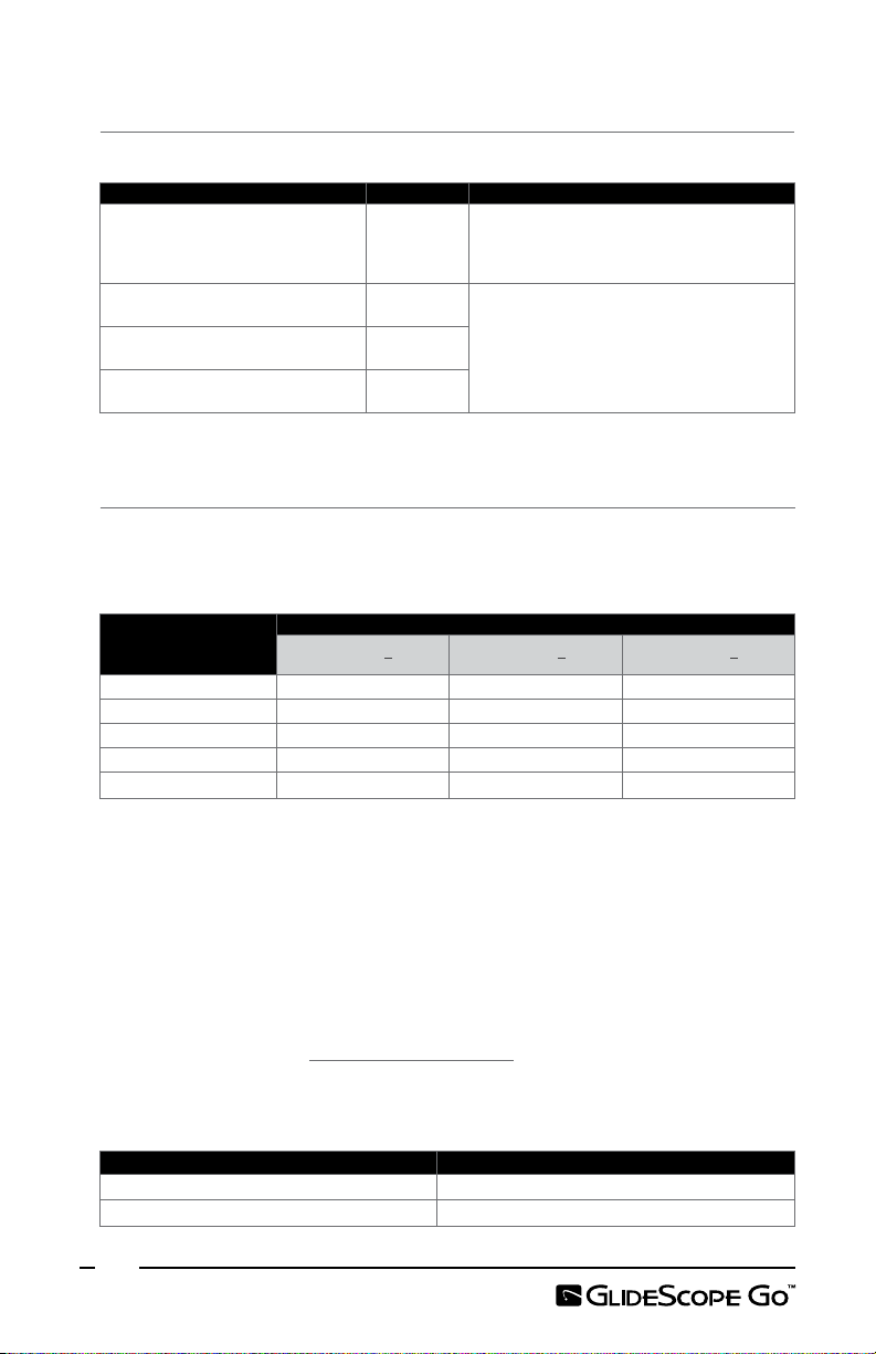
Table 7. Disinfection and Sterilization Solutions for the VideoBaton 2.0 Large
®
Disinfection
Level
Low As per chemical manufacturer’s instructions
Low As per chemical manufacturer’s instructions
Up to 1100 cycles as per chemical manufacturer’s
instructions
Low
Low
High As per chemical manufacturer’s instructions
High As per chemical manufacturer’s instructions
High As per chemical manufacturer’s instructions
High
High As per chemical manufacturer’s instructions
Up to 750 cycles as per chemical manufacturer’s
instructions
Exposure: Using fresh wipe(s), wet all surfaces and allow
to remain wet for 3 minutes.
Rinse: Not applicable. Allow the component to
thoroughly air dry.
100 cycles in a Medivators Advantage® Plus automated
endoscope reprocessor (AER) disinfection routine meeting
the following requirements:
• Concentration of disinfectant – 750‑950 parts
per million
• Temperature – 28°C–32°C (82.4°F – 89.6°F)
• Exposure time – 5 minutes
• AER configuration – Hookup 2‑8‑002HAN rev A
• AER parameter set – 1‑35‑101 C DISF
Conditions
Product
Bleach (500
ppm)
Isopropyl alcohol
solution (70%)
Oxivir® Tb Wipes Low
Sani‑Cloth®
Bleach Wipes
SaniCloth® AF3
Germicidal
Wipes
ASP®
CIDEXPLUS®
28Day Solution
ASP® CIDEX®
OPA
Metrex®
MetriCide®
Plus30
Medivators®
Rapicide
Sultan®
Healthcare
Sporox® II
17
Page 24

Product
STERIS® S40™
or S20™
STERIS® V‑PRO®
low temperature
sterilization
systems
ASP® Hydrogen
PeroxideGas
Plasma
1. Ensure the equipment is clean according to the previous steps.
2. Prepare and condition the disinfection solution according to the solution
manufacturer’s instructions and the conditions stated in Tabl e 7.
3. Disinfect the video baton according to the conditions stated in Tabl e 7. The
exposure process and times vary depending on the solution and the component.
Note: If you are using a wipe method, rewipe the component as needed in order to
ensure that it remains visibly wet for the duration of the exposure period. You may
use multiple wipes as necessary.
4. If applicable, rinse the video baton according to the solution manufacturer’s
instructions.
5. Dry the video baton by using a sterile cloth, hospital‑grade clean air, or a
low‑temperature dryer.
Note: If you are using a wipe method, allow the component to thoroughly air dry.
6. Inspect the video baton according to the instructions in the following procedure,
and then store the disinfected video baton in a clean environment.
Disinfection
Level
Standard cycles in the following processors:
STERIS® SYSTEM 1® (outside U.S.)
Sterilization
Sterilization Up to 200 cycles as per manufacturer’s instructions
Sterilization
SYSTEM 1E® (in U.S.)
SYSTEM 1 EXPRESS (outside U.S.)
SYSTEM 1 PLUS (outside U.S.)
STERRAD® 100S (in U.S.),
STERRAD® 100S short cycle (outside U.S.),
STERRAD® NX standard cycle, or
STERRAD® 100NX standard cycle
Conditions
PROCEDURE 5. CLEAN THE CHARGING CRADLE
Clean the charging cradle when it is visibly soiled and on a regular basis, as per a schedule
established by the medical care facility or provider.
CAUTION
1. Ensure the monitor is not in the charging cradle, and then unplug the device.
2. Using a solution from Compatibility & Availability on page14, wipe the exterior
until all visible contamination has been removed.
Do not submerge the charging cradle in a liquid solution.
18
Page 25

MAINTENANCE & SAFETY
WARNING
cause serious injury to the operator or damage to the instrument and will void the warranty.
Contact Verathon® Customer Care for all servicing needs.
WARNING
Do not attempt to open the system components. This may
No modification of this equipment is allowed.
PERIODIC INSPECTIONS
In addition to the user performing routine inspections before and after every use, periodic
inspections should be performed to ensure safe and effective operation. It is recommended
that you perform a full visual inspection of all components at least every three months. The
inspector should check the system for the following:
• External damage to the equipment
• Damage to the power adapter
• Damage to the connectors
Report any suspected defects to Verathon Customer Care or your local representative.
BATTERY
After 300 charge and discharge cycles, the battery capacity is approximately 80% of the
initial capacity. Under normal operating conditions, this may happen at around 3 years. For
more information about the battery, see Battery Specifications on page21.
The battery is not user‑replaceable. Do not attempt to replace the battery. Any attempts to
replace the battery by unauthorized service technicians may cause serious harm to the user
and will void the warranty. For more information, contact Verathon Customer Care or your
local representative.
SYSTEM SOFTWARE
This manual documents the most current version of the software. If your monitor does not
function as described in this manual, or to determine if your software should be updated,
contact Verathon Customer Care. Do not perform any software upgrades from third‑party
vendors or attempt to modify the existing software. Doing so may damage the monitor
and void the warranty.
19
Page 26

DEVICE REPAIR
The system components are not user‑serviceable. Verathon does not make available
any type of circuit diagrams, component parts lists, descriptions, or other information
that would be required for repairing the device and related accessories. All service must
be performed by a qualified technician. If you have any questions, contact Verathon®
Customer Care or your local Verathon representative.
DEVICE DISPOSAL
The system and related accessories may contain batteries and other environmentally
hazardous materials. When the instrument has reached the end of its useful service life, it
must be disposed of in accordance with WEEE requirements. Coordinate disposal through
your Verathon Service Center, or alternatively, follow your local protocols for hazardous
waste disposal.
WARRANTY
Verathon products and software are warranted against defects in material and workmanship
according to the Terms and Conditions of Sale. This limited warranty applies for the specified
term from the date of shipment from Verathon and applies only to the original purchaser of
the system. Warranty coverage applies to the following system components:
Component Warranty Term
Monitor 2 years
Charging cradle 1 year
Video Baton 2.0 1 year
Additional reusable components purchased either singularly or as a part of a system are
warranted separately. Consumable items are not covered under this warranty.
For more information about your warranty or to purchase a Premium Total Customer CareSM
warranty that extends the limited warranty on your system, please contact Verathon Customer
Care or your local representative.
PRODUCT SPECIFICATIONS
SYSTEM SPECIFICATIONS
Table 8. System Specifications
General Specifications
Classification: Electrical Class II / Internally Powered, Applied Part BF
Monitor IP67
Ingress protection
against water:
20
Single‑use blade IPX4
Video baton IPX8
Single‑use Stat N/A
Page 27
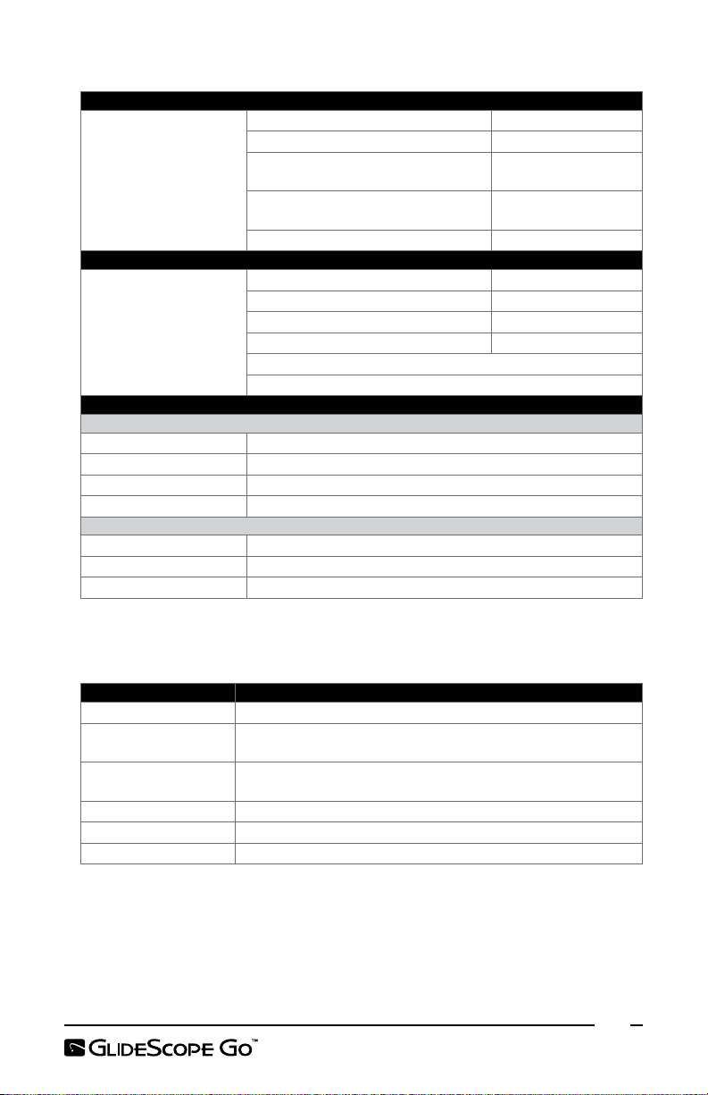
Table 8. System Specifications
General Specifications
Monitor 1500 uses or 3 years
Spectrum™ LoPro Single‑Use blade 1use or 3‑year shelf life
Spectrum DirectView™ MAC
Expected product life:
Monitor:
Operating temperature: 10 to 40°C (50 to 104°F)
Charging temperature: 10 to 35°C (50 to 95°F)
Relative humidity: 0 to 95% (non‑condensing)
Atmospheric pressure: 700–1060hPa
Temperature: ‑20 to 40°C (‑4 to 104°F)
Relative humidity: 0 to 95% (non‑condensing)
Atmospheric pressure: 700–1060hPa
Single‑Use blade
GlideScope video baton 2.0 Large
(3‑4)
GVL® Single‑use Stat 1 use or 3‑year shelf life
Monitor Component Specifications
Height 86mm (3.39in)
Width 98mm (3.86in)
Depth 47mm (1.85in)
Weight (approximate) 0.25kg (8.82oz)
LCD: 320 x 240 px, 8.9 cm (3.5 in)
Frames per second (displayed and recorded): 30
Operating & Storage Specifications
Operating Conditions
Shipping & Storage Conditions
1use or 1‑year shelf life
2 years or 2000 cycles
BATTERY SPECIFICATIONS
Table 9. Battery Specifications
Condition Description
Battery type: Lithium‑ion
Battery life:
Charging time:
Rated capacity: 1200mAh or higher
Nominal voltage: 3.7V
Max charging voltage: 4.2V
Under normal operating conditions, a fully charged, new battery
lasts approximately 100minutes, (5) intubations without recording.
Charging time off line will take no more than 3hours from an
empty battery to a full charge.
21
Page 28

ELECTROMAGNETIC COMPATIBILITY
The system is designed to be in compliance with IEC60601‑1‑2:2007, which contains
electromagnetic compatibility (EMC) requirements for medical electrical equipment.
The limits for emissions and immunity specified in this standard are designed to provide
reasonable protection against harmful interference in a typical medical installation.
The system complies with the applicable essential performance requirements specified
in IEC60601‑1 and IEC60601‑2‑18. Results of immunity testing show that the essential
performance of the system is not affected under the test conditions described in the
following tables.
ELECTROMAGNETIC IMMUNITY
Table 10. Guidance and Manufacturer’s Declaration —Electromagnetic Immunity
The system is intended for use in the electromagnetic environment specified below. The customer or the
user of the system should ensure that it is used in such an environment.
Immunity Tests IEC60601 Test Level
Electrostatic
discharge (ESD)
IEC61000‑4‑2
Electrical fast
transient/burst
IEC61000‑4‑4
Surge
IEC61000‑4‑5
Voltage
dips, short
interruptions and
voltage variations
on power supply
input lines
IEC61000‑4‑11
Power frequency
(50/60Hz)
magnetic field
IEC61000‑4‑8
Conducted RF
IEC61000‑4‑6
± 6kV contact
± 8kV air
± 2kV for power
supplylines
± 1kV for input/
outputlines
± 1kV line(s) to line(s)
± 2kV line(s) to earth
<5%Ut (>95% dip in Ut)
for 0.5cycle
40%Ut (60% dip in Ut)
for 5cycles
70%Ut (30% dip in Ut)
for 25cycles
<5%Ut (>95% dip in Ut)
for 5s
3A/m In compliance
3Vrms
150kHz to 80MHz
Compliance
Level
In compliance
In compliance
In compliance
In compliance
3V
Electromagnetic Environment –
Guidance
Floors should be wood, concrete,
or ceramic tile. If floors are covered
with synthetic material, the relative
humidity should be at least 30%.
Mains power quality should be that
of a typical commercial or hospital
environment.
Mains power quality should be that
of a typical commercial or hospital
environment.
Mains power quality should be that
of a typical commercial or hospital
environment. If the user of the
system requires continued operation
during power mains interruptions,
it is recommended that the system
be powered from an uninterruptible
power supply or a battery.
Power frequency magnetic fields
should be at levels characteristic
of a typical location in a typical
commercial or hospital environment.
Portable and mobile RF
communications equipment should
be used no closer to any part of the
system, including cables, than the
recommended separation distance
calculated from the equation
applicable to the frequency of the
transmitter.
Recommended separation
distance d (m)
d=1.2 √P
22
Page 29

Table 10. Guidance and Manufacturer’s Declaration —Electromagnetic Immunity
The system is intended for use in the electromagnetic environment specified below. The customer or the
user of the system should ensure that it is used in such an environment.
Immunity Tests IEC60601 Test Level
Compliance
Level
Electromagnetic Environment –
Guidance
d=1.2 √P 80MHz to 800MHz
d=2.3 √P 800MHz to 2.5GHz
where P is the maximum output
power rating of the transmitter
in watts (W) according to the
transmitter manufacturer and d is the
recommended separation distance in
meters (m).
Radiated RF
IEC61000‑4‑3
3V/m
80MHz to 2.5GHz
3V/m
Field strengths from fixed RF
transmitters, as determined by an
electromagnetic site survey,a should
be less than the compliance level in
each frequency range.
b
Interference may occur in the vicinity
of equipment marked with the
following symbol:
Note: U t is the AC mains voltage prior to application of the test level.
At 80MHz and 800MHz, the higher frequency range applies.
These guidelines may not apply in all situations. Electromagnetic propagation is affected by absorption
and reflection from structures, objects and people.
a. Field strengths from fixed transmitters, such as base stations for radio (cellular/cordless) telephones and land
mobile radios, amateur radio, AM and FM radio broadcast and T V broadcast cannot be predicted theoretically
with accuracy. To assess the elec tromagnetic environment due to fixed RF transmitters, an electromagnetic site
survey should be considered. If the measured field strength in the location in which the system is used exceeds
the applicable RF compliance level above, the system should be observed to verify normal operation. If abnormal
performance is observed, additional measures may be necessary, such as re ‑orienting or relocating the system.
b. Over the frequency range 150kHz to 80MHz, field strengths should be less than 3V/m.
23
Page 30
ELECTROMAGNETIC EMISSIONS
Table 11. Guidance and Manufacturer’s Declaration— Electromagnetic Emissions
The system is intended for use in the electromagnetic environment specified below. The customer or
the user of the system should ensure that it is used in such an environment.
Emissions Test Compliance Electromagnetic Environment – Guidance
RF emissions
CI S P R 11
RF emissions
CI S P R 11
Harmonic emissions
IEC61000‑3‑2
Voltage fluctuations/flicker emissions
IEC6100 0‑3‑3
Group 1
Class A
Class A
Complies
The system uses RF energy only for its
internal function. Therefore, its RF emissions
are very low and are not likely to cause any
interference in nearby electronic equipment.
The system is suitable for use in all
establishments other than domestic and those
directly connected to the public low‑voltage
power supply network that supplies buildings
used for domestic purposes.
RECOMMENDED SEPARATION DISTANCES
Table 12. Recommended Separation Distances between Portable and Mobile RF Communications
The system is intended for use in an electromagnetic environment in which radiated RF disturbances
are controlled. The customer or the user of the system can help prevent electromagnetic interference
by maintaining a minimum distance between portable and mobile RF communications equipment
(transmitters) and the system as recommended below, according to the maximum output power of the
communications equipment.
For transmitters rated at a maximum output power not listed above, the recommended separation
distance d in meters (m) can be estimated using the equation applicable to the frequency of the
transmitter, where P is the maximum output power rating of the transmitter in watts (W) according to
the transmitter manufacturer.
Note: At 80MHz and 800MHz, the separation distance for the higher frequency range applies.
These guidelines may not apply in all situations. Electromagnetic propagation is affected by absorption
and reflection from structures, objects and people.
Equipment and the System
Rated maximum
output power of
transmitter (W)
0.01 0.12 0.12 0.23
0.1 0.38 0.38 0.73
1 1.2 1.2 2.3
10 3.8 3.8 7.3
100 12 12 23
Separation distance according to frequency of transmitter (m)
150kHz to 80MHz
d=1.2 √P
80MHz to 800MHz
d=1.2 √P
800MHz to 2.5GHz
d=2.3 √P
ACCESSORY CONFORMANCE TO STANDARDS
To maintain electromagnetic interference (EMI) within certified limits, the system must be
used with the cables, components, and accessories specified or supplied by Verathon®. For
additional information, see System Parts & Accessories. The use of accessories or cables
other than those specified or supplied may result in increased emissions or decreased
immunity of the system.
Table 13. EMC Standards for Accessories
Accessory Max Cable Length
Monitor power adapter 1.5m (4.9ft)
Charging cradle power adapter 1.5m (4.9ft)
24
Page 31

FR
FRANÇAIS
INFORMATIONS IMPORTANTES
COORDONNÉES
Pour obtenir des informations supplémentaires concernant votre système, contactez le
service client de Verathon® ou consultez le site verathon.com/support.
Siège social Représentant en Europe Fabricant
Verathon Inc.
20001 North Creek Parkway
Bothell, WA 98011 États-Unis
Tél.: 800.331.2313
(États-Unis/Canada)
Tél.: 425 867 1348
Fax: 425 883 2896
À PROPOS DE CE MANUEL
Les informations contenues dans le présent manuel peuvent être modifiées a tout moment,
sans preavis. Pour obtenir les informations les plus récentes, consultez la documentation
disponible en ligne sur verathon.com/product-documentation.
Copyright© 2017 Verathon Inc. Tous droits réservés. Aucune partie du présent manuel
ne peut être copiée ou transmise de quelque manière que ce soit sans le consentement
explicite écrit de Verathon Inc. Ambient Light Reduction, DirectView, Dynamic Light Control,
GlideRite, GlideScope, GlideScope Go, le symbole GlideScope, Spectrum, Verathon et le
symbole Torche de Verathon sont des marques ou des marques déposées de Verathon Inc.
L'ensemble des autres marques et noms de produits sont des marques ou des marques
commerciales appartenant à leurs propriétaires respectifs.
Verathon Medical (Europe) B.V.
Willem Fenengastraat 13
1096 BL Amsterdam
Pays-Bas
Tél.: +31 (0) 20 210 30 91
Fax: +31 (0) 20 210 30 92
Verathon Medical (Canada) ULC
2227 Douglas Road
Burnaby, BC V5C 5A9
Canada
Tél.: 604 439 3009
Fax: 604 439 3039
DESCRIPTION DU PRODUIT
GlideScope Go est un système de vidéolaryngoscope portable conçu pour offrir une
visualisation claire, directe et indirecte, des voies aériennes de manière à faciliter l'intubation
rapide. Le moniteur couleur inclinable de 3,5 pouces réutilisable et la batterie rechargeable
peuvent être complètement immergés pour le nettoyage. Les paramètres utilisateur
disponibles, qui comprennent l'enregistrement automatique, l'arrêt automatique et l'affichage
du contenu, offrent à l'utilisateur une expérience plus personnalisée. Ce système s'intègre au
portefeuille de produits Spectrum™, qui comprend des lames entièrement jetables pouvant
être remplacées sans mettre le moniteur hors tension. Le système GlideScope Go est idéal dans
des conditions de travail difficiles. Il est adapté aux voies aériennes normales et complexes et
peut être utilisé chez une grande diversité de patients et dans de multiples cadres cliniques.
UTILISATION PRÉVUE
Le système GlideScope Go est destiné à l'usage des professionnels médicaux qualifiés dans
le but d’obtenir une vue claire et dégagée des voies aériennes et des cordes vocales dans le
cadre d'actes médicaux.
25
Page 32

DÉCLARATION DE PRESCRIPTION
La loi fédérale (des États-Unis) limite la vente de ce dispositif aux médecins ou sur
prescription médicale.
AVIS À TOUS LES UTILISATEURS
Le système doit être utilisé exclusivement par des personnes formées et habilitées par un
médecin, ou par des prestataires de santé formés et habilités par l’établissement fournissant
les soins au patient. Verathon® recommande à tous les utilisateurs de respecter les consignes
suivantes:
• Lire le manuel avant d'utiliser l'instrument
• Demander conseil à une personne qualifiée
• S'entraîner à utiliser le vidéolaryngoscope sur un mannequin avant de passer à une
utilisation clinique
• Acquérir de l'expérience clinique sur des patients dont les voies aériennes sont normales
MISES EN GARDE ET AVERTISSEMENTS
Les avertissements sont des mentions destinées à alerter l'utilisateur du risque de blessure,
de décès ou d'autres graves effets indésirables associés à l'utilisation ou la mauvaise
utilisation du dispositif. Les mises en garde sont des mentions destinées à alerter l'utilisateur
du risque de problèmes, tels qu'un dysfonctionnement, une panne ou un dommage,
associés à l'utilisation ou la mauvaise utilisation du produit. Dans tout le manuel, prêtez
attention aux sections intitulées Important, car elles contiennent des rappels ou des résumés
des mises en garde suivantes lorsqu'elles s'appliquent à un composant ou une situation
spécifique. Respectez les avertissements et mises en garde ci-dessous.
ATTENTION
spéciales en matière de compatibilité électromagnétique (CEM) et doit être installé et utilisé
conformément aux instructions présentées dans ce manuel. Pour plus d'informations,
consultez la section Compatibilité électromagnétique à la page39.
ATTENTION
un enregistrement vidéo. Le retrait de la clé USB avant la fin de la sauvegarde d'un
enregistrement risque de corrompre le fichier vidéo.
ATTENTION
conformément aux procédures basse température recommandées par Verathon.
ATTENTION
de connecter un adaptateur d'alimentation ou une station de recharge.
ATTENTION
désinfecter le moniteur. Vous risquez de rayer l'écran, ce qui endommagerait irrémédiablement
le dispositif.
ATTENTION
Ce dispositif électromédical nécessite des précautions
Déconnectez la lame ou éteignez le moniteur pour sauvegarder
Ce produit doit être nettoyé, désinfecté ou stérilisé
Assurez-vous que le port micro-USB du moniteur est sec avant
Veillez à ne pas utiliser d'outils abrasifs pour nettoyer ou
N'immergez pas la station de recharge dans une solution liquide.
26
Page 33

AVERTISSEMENT
Le moniteur doit être nettoyé avant la première utilisation.
AVERTISSEMENT
compatibilité électromagnétique, utilisez uniquement les accessoires et les composants
recommandés par Verathon, notamment le module d'alimentation fourni, agréé pour un
usage médical.
AVERTISSEMENT
distale du vidéolaryngoscope, veillez à regarder dans la bouche du patient, et non pas l'écran.
Dans le cas contraire, il existe un risque de blessure, notamment des amygdales ou du voile
du palais.
AVERTISSEMENT
ou la mise au rebut des solutions de nettoyage, de désinfection ou de stérilisation.
AVERTISSEMENT
à usage unique. Une réutilisation, un nouveau traitement ou une restérilisation peuvent
entraîner un risque de contamination du dispositif.
AVERTISSEMENT
AVERTISSEMENT
blesser gravement l'opérateur ou endommager l'instrument et annuler la garantie. Contactez
le service client de Verathon pour tous les besoins d'entretien.
AVERTISSEMENT
entrer en contact avec le patient et sa température peut dépasser 41 °C (106 °F) dans le
cadre d'une utilisation normale. Le contact du patient avec cette zone de la lame pendant
l'intubation est peu probable, car cela provoquerait l'obstruction de la vue de la caméra. Ne
maintenez pas un contact continu de la lame sur cette zone pendant plus d'une minute ;
en effet, cela pourrait provoquer une lésion thermique telle qu'une brûlure des muqueuses.
Pour réduire le risque de choc électrique et préserver la
Lorsque vous guidez la sonde endotrachéale dans l'extrémité
Veillez à suivre les instructions du fabricant pour la manipulation
Évitez de réutiliser, retraiter ou resteriliser un composant
Aucune modification de cet équipement n'est autorisée.
N'essayez pas d'ouvrir les composants du système. Cela pourrait
La zone qui entoure la caméra dans le vidéolaryngoscope peut
AVERTISSEMENT
compatibles avec ce système:
• 0574-0176 (Spectrum™ LoPro S3) • 0574-0178 (Spectrum MAC S3)
• 0574-0177 (Spectrum LoPro S4) • 0574-0179 (Spectrum MAC S4)
Reportez-vous aux numéros pour évaluer si une lame est compatible avec le système. Pour
plus d'informations à propos des composants et accessoires compatibles, voir page29.
AVERTISSEMENT
fluides corporels susceptibles de transmettre des agents pathogènes, toutes les installations
de nettoyage doivent être conformes à la norme américaine OSHA 29 CFR 1910.1030 sur les
pathogènes à diffusion hématogène ou à une norme équivalente. Pour plus d'informations,
consultez le site www.osha.gov.
Les lames GlideScope portant les numéros suivants ne sont pas
Le produit risquant d'être contaminé par du sang humain ou des
27
Page 34

AVERTISSEMENT
correctement et ne présente aucun signe de dommage. N'utilisez pas ce produit si le dispositif
semble être endommagé. Veillez à ce que des méthodes et du matériel alternatifs de gestion
des voies aériennes soient disponibles.
Avant chaque utilisation, vérifiez que l'instrument fonctionne
AVERTISSEMENT
contamination avant de le placer dans la station de recharge.
AVERTISSEMENT
charger le moniteur GlideScope Go.
Assurez-vous que le moniteur est propre et exempt de
La station de recharge doit être utilisée uniquement pour
SYMBOLES
Pour obtenir la liste complète des symboles de mise en garde, d'avertissement et
d'information utilisés sur ce produit et sur d'autres produits Verathon®, veuillez vous
reporter au répertoire des symboles Verathon à l'adresse verathon.com/symbols.
INTRODUCTION
PRÉSENTATION GÉNÉRALE DU SYSTÈME
Le système GlideScope Go comprend un petit moniteur portable et utilise des
vidéolaryngoscopes GlideScope Spectrum. Il s'agit de lames en plastique durable et à usage
unique qui doivent être éliminées après utilisation. Les lames à usage unique sont identifiées
par un S dans leur nom, par exemple LoPro S4. Ces lames intègrent les technologies
suivantes:
• Dynamic Light Control™ : optimise la luminosité et la clarté des images.
• Ambient Light Reduction™ : diminue l'excédent de lumière réfléchie afin d'améliorer
encore la qualité des images.
Figure 1. Moniteur GlideScope Go
Port micro-USB et
station de recharge
Bras du connecteur
Connecteur de lame
28
Voyant
Bouton Alimentation
Écran LCD
Page 35

PIÈCES ET ACCESSOIRES DU SYSTÈME
COMPOSANTS REQUIS DU SYSTÈME
Les composants suivants sont indispensables au bon fonctionnement du système:
• Moniteur GlideScope Go
• Adaptateur secteur
• Une ou plusieurs lames des tailles suivantes:
Spectrum™ LoPro S1 (0574-0165)
Spectrum LoPro S2 (0574-0166)
Spectrum LoPro S3 (0574-0194)
Spectrum LoPro S4 (0574-0195)
Spectrum DirectView™ MAC S3 (0574-0187)
Spectrum DirectView MAC S4 (0574-0188)
ACCESSOIRES SUPPLÉMENTAIRES
Les accessoires suivants sont facultatifs et peuvent être utilisés avec le système:
• Station de recharge
• Petite mallette de transport
• Stylet rigide GlideRite® (pour les sondes endotrachéales de 6,0 mm ou plus)
• Stylet à usage unique GlideRite - Petit (pour les sondes endotrachéales de 3,0 à 4,0 mm)
• Lecteur flash USB hybride micro à standard pour configurer les paramètres et
enregistrer la vidéo
CONFIGURATION DU SYSTÈME
PROCÉDURE 1. INSPECTION INITIALE
1. Vérifiez que vous avez reçu les composants appropriés pour votre système en
contrôlant la liste des pièces fournies avec le système.
2. Vérifiez si les composants présentent des dommages.
3. Si l'un des composants est manquant ou endommagé, notifiez-le au transporteur et
au service client ou à votre représentant local Verathon®.
PROCÉDURE 2. CHARGE DE LA BATTERIE
AVERTISSEMENT
compatibilité électromagnétique, utilisez uniquement les accessoires et les composants
recommandés par Verathon, notamment le module d'alimentation fourni, agréé pour un
usage médical.
AVERTISSEMENT
contamination avant de le placer dans la station de recharge.
Pour plus d'informations sur la batterie et les conditions de charge, voir Spécifications de la
batterie à la page39.
1. Raccordez l'adaptateur secteur à une prise électrique de qualité hôpital.
Pour réduire le risque de choc électrique et préserver la
Assurez-vous que le moniteur est propre et exempt de
29
Page 36

2. Assurez-vous que le port micro-USB sur le moniteur est sec.
3. Si vous chargez directement à partir de l'adaptateur d'alimentation, connectez-le
auport microUSB du moniteur.
Si vous chargez avec la station de recharge, connectez l'adaptateur d'alimentation
auport microUSB de la station, puis placez le moniteur dans la station.
Pour obtenir la descriptions des états des voyants, reportez-vous au tableau suivant.
Tableau 1. Description de l'état des voyants
État du voyant Description
Vert fixe La batterie est complètement chargée.
Orange fixe
Rouge fixe
Rouge
clignotant
La batterie est en cours de charge à l'aide d'un adaptateur
secteur agréé ou équivalent.
La batterie est en cours de charge à l'aide d'un adaptateur
secteur non agréé.
*
Erreur. Un problème s'est produit au niveau de la batterie ou du
circuit de charge.
Éteint Pas de charge.
* L'utilisation d'un adaptateur secteur non agréé risque de ne pas charger correctement la batterie.
Veuillez remplacer l'adaptateur secteur non agréé par l'adaptateur fourni avec le système.
4. Laissez la batterie se charger jusqu'à ce que le voyant s'allume en vert fixe.
PROCÉDURE 3. CONFIGURATION DES PARAMÈTRES UTILISATEUR
L'outil Paramètres utilisateur est un outil Java, disponible sur la clé USB.
1. Connectez la clé USB au port USB d'un ordinateur.
2. Naviguez jusqu'à la clé USB, puis ouvrez l'outil Paramètres utilisateur.
3. Configurez les paramètres requis, puis cliquez sur Enregistrer.
4. Dans la boîte de dialogue Enregistrer sous, naviguez jusqu'à la clé USB, puis cliquez
sur Enregistrer.
5. Assurez-vous que le moniteur est hors tension, puis insérez la clé dans le port
micro-USB du moniteur.
6. Sur le moniteur, appuyez sur le bouton Alimentation. Le moniteur s'allume et les
paramètres sont automatiquement mis à jour. Le fichier des paramètres est alors
automatiquement supprimé pour éviter l'écrasement des paramètres de date et
d'heure.
30
Page 37

PROCÉDURE 4. FIXATION DE LA LAME
La lame se fixe au bras du connecteur du moniteur. Le moniteur pivote sur le bras du
connecteur, afin de vous permettre de régler un angle initial pour commencer l'intubation.
Il est recommandé de laisser la lame stérile à usage unique dans l'emballage pendant la
connexion et jusqu'à ce que vous soyez prêt à réaliser une procédure d'intubation.
1. Alignez la flèche située sur le moniteur sur celle qui se trouve sur la lame à usage
unique, puis insérez entièrement le connecteur dans le port du connecteur de la lame.
Marques d'alignement
PROCÉDURE 5. RÉALISATION D’UN TEST DE FONCTIONNEMENT
Avant la première utilisation du dispositif, assurez-vous que le système fonctionne correctement.
1. Chargez entièrement la batterie du moniteur.
2. Raccordez le vidéolaryngoscope au moniteur, conformément à la procédure décrite
précédemment.
3. Appuyez sur le bouton Alimentation. Le moniteur s'allume.
4. Observez l’écran et vérifiez que la vidéo affichée provient bien de la lame.
Remarque: Les bords de la lame peuvent être capturés dans la vue de la caméra.
L'image sert de cadre de référence au cours de l'intubation et garantit que
l'orientation de l'image est correcte sur le moniteur.
UTILISATION DU DISPOSITIF
Avant d'utiliser l'appareil, suivez les instructions décrites dans le chapitre Configuration du
système.
PROCÉDURE 1. PRÉPARATION DU SYSTÈME
AVERTISSEMENT
compatibles avec ce système:
• 0574-0176 (Spectrum™ LoPro S3) • 0574-0178 (Spectrum MAC S3)
• 0574-0177 (Spectrum LoPro S4) • 0574-0179 (Spectrum MAC S4)
Reportez-vous aux numéros pour évaluer si une lame est compatible avec le système. Pour
plus d'informations à propos des composants et accessoires compatibles, voir page29.
Les lames GlideScope portant les numéros suivants ne sont pas
31
Page 38

AVERTISSEMENT
correctement et ne présente aucun signe de dommage. N'utilisez pas ce produit si le dispositif
semble être endommagé. Veillez à prévoir des méthodes et du matériel alternatifs de gestion
des voies aériennes.
Tableau 2. Tailles de vidéolaryngoscope
Lame GlideScope Référence
Spectrum™ LoPro S1 0574-0165 1,5–3,8kg (3,3–8,4livres)
Spectrum LoPro S2 0574-0166 1,8-10kg (4-22livres)
Spectrum LoPro S3 0574-0194
Spectrum LoPro S4 0574-0195 40kg (88livres) à adulte de grande taille
Spectrum DirectView™ MAC S3 0574-0187 Adulte de taille moyenne
Spectrum DirectView MAC S4 0574-0188 Adulte de grande taille
1. Assurez-vous que chaque composant du système GlideScope a été nettoyé
ou désinfecté correctement, conformément aux indications du Tableau 3 à la
page34.
2. Utilisez les informations du Tableau 2, associées à une évaluation clinique du
patient et à l'expérience et au jugement du praticien, pour sélectionner le
vidéolaryngoscope GlideScope approprié pour le patient.
3. Fixez la lame au moniteur conformément à la rubrique Fixation de la lame à la
page31.
Avant chaque utilisation, vérifiez que l'instrument fonctionne
*
Poids/Taille de patient
recommandés
10kg (22livres) à adulte de taille
moyenne
PROCÉDURE 2. RÉALISATION D’UNE INTUBATION
AVERTISSEMENT
entrer en contact avec le patient et sa température peut dépasser 41 °C (106 °F) dans le
cadre d'une utilisation normale. Le contact du patient avec cette zone de la lame pendant
l'intubation est peu probable, car cela provoquerait l'obstruction de la vue de la caméra. Ne
maintenez pas un contact continu de la lame sur cette zone pendant plus d'une minute ;
en effet, cela pourrait provoquer une lésion thermique telle qu'une brûlure des muqueuses.
AVERTISSEMENT
distale du vidéolaryngoscope, veillez à regarder dans la bouche du patient, et non pas l'écran.
Dans le cas contraire, il existe un risque de blessure, notamment des amygdales ou du voile
du palais.
Pour réaliser une intubation, Verathon® recommande d'utiliser la technique GlideScope en
4étapes, comme indiqué dans cette procédure. Chaque étape commence par les vérifications
que doit effectuer l’utilisateur afin de réaliser cette action. Avant de commencer cette
procédure, vérifiez que le moniteur reçoit une image exacte depuis le vidéolaryngoscope.
1. Regardez dans la bouche: tenez le vidéolaryngoscope dans la main gauche,
introduisez-le dans l'axe médian de l'oropharynx.
* Les plages de poids sont approximatives. Un professionnel médical doit évaluer quel dispositif choisir selon le patient.
La zone qui entoure la caméra dans le vidéolaryngoscope peut
Lorsque vous guidez la sonde endotrachéale dans l'extrémité
32
Page 39

2. Regardez l'écran: identifiez l'épiglotte et manipulez la lame afin d'obtenir la
meilleure vue de la glotte possible.
3. Regardez dans la bouche: guidez délicatement l'extrémité distale du tube en
position, en direction de l'extrémité du laryngoscope.
4. Regardez l'écran: terminez l'intubation en faisant pivoter ou en inclinant
délicatement le tube afin de le réorienter selon le cas.
PROCÉDURE 3. ENREGISTREMENT DE L'INTUBATION
ATTENTION
un enregistrement vidéo. Le retrait de la clé USB avant la fin de la sauvegarde d'un
enregistrement risque d'endommager le fichier vidéo.
1. Lancez l'enregistrement en vous assurant que les conditions suivantes sont réunies:
• Une lame est connectée au moniteur.
• Une clé USB est connectée au port micro-USB du moniteur.
• Le moniteur est sous tension.
• La fonction d'enregistrement est activée dans les paramètres de l'utilisateur.
Une fois ces conditions réunies, l'enregistrement débute automatiquement.
2. Arrêtez l'enregistrement en appuyant sur le bouton d'alimentation et en le
maintenant enfoncé jusqu'à ce que le moniteur soit entièrement hors tension.
L'enregistrement s'interrompt également si la lame est déconnectée, si la capacité
de la clé USB est trop faible ou si la charge restante de la batterie ne peut assurer
que moins d'une minute d'alimentation.
3. Pour visionner l'enregistrement, insérez la clé USB dans l'ordinateur, puis affichez le
fichier .avi. Les fichiers sont automatiquement nommés avec la date et l'heure du
système.
Déconnectez la lame ou éteignez le moniteur pour sauvegarder
NETTOYAGE ET DÉSINFECTION
ATTENTION
désinfecter le moniteur. Vous risquez de rayer l'ecran, ce qui endommagerait irrémédiablement
le dispositif.
ATTENTION
conformément aux procédures basse température recommandées par Verathon.
Veillez à ne pas utiliser d'outils abrasifs pour nettoyer ou
Ce produit doit être nettoyé, désinfecté ou stérilisé
AVERTISSEMENT
fluides corporels susceptibles de transmettre des agents pathogènes, toutes les installations
de nettoyage doivent être conformes à la norme américaine OSHA 29 CFR 1910.1030 sur les
pathogènes à diffusion hématogène ou à une norme équivalente. Pour plus d'informations,
consultez le site www.osha.gov.
AVERTISSEMENT
ou la mise au rebut des solutions de nettoyage, de désinfection ou de stérilisation.
Le produit risquant d'être contaminé par du sang humain ou des
Veillez à suivre les instructions du fabricant pour la manipulation
33
Page 40

AVERTISSEMENT
Évitez de réutiliser, retraiter ou restériliser un composant à usage
unique. Une réutilisation, un nouveau traitement ou une restérilisation peuvent entraîner un
risque de contamination du dispositif.
AVERTISSEMENT
Le moniteur doit être nettoyé avant la première utilisation.
Les lames à usage unique sont fournies stérilisées à l'oxyde d'éthylène. Il n'est pas utile
de les nettoyer, de les désinfecter ou de les stériliser avant l'utilisation. Éliminez les
lames à usage unique après utilisation. N'essayez pas de désinfecter et réutiliser des
vidéolaryngoscopes à usage unique.
Tableau 3 Le tableau suivant décrit l'évaluation des risques pour chaque composant du
système, notamment la classification Spaulding pour le niveau minimum de désinfection
requis. Avant chaque utilisation, assurez-vous que chaque composant du système a été
nettoyé, désinfecté ou stérilisé conformément aux indications figurant dans ce tableau.
Tableau 3. Classification des risques du système
Dispositif Utilisation
Moniteur Réutilisable Non critique X
Station de recharge
Lames à usage unique
Stylet rigide GlideRite
Stylet à usage unique
GlideRite
* Nettoyez la station de recharge lorsqu'elle porte des souillures visibles et régulièrement.
† Pour obtenir des instructions, consultez le Manuel d'utilisation et de maintenance du stylet rigide GlideRite.
§ Les lames et les stylets à usage unique ne doivent pas être réutilisés. Éliminez les éléments à usage unique après
utilisation.
X Les cases cochées indiquent le niveau de désinfection minimum requis.
Les zones grisées indiquent que le niveau de désinfection ou de stérilisation n'est pas requis ou pas compatible avec
le dispositif.
Les parties non grisées indiquent des niveaux de désinfection ou de stérilisation acceptables en raison de leur
compatibilité avec les matériaux du dispositif.
*
Réutilisable Non critique
À usage
§
®†
§
unique
Réutilisable Semi-critique X
À usage
unique
Classification
Spaulding
—
—
Nettoyé
Désinfecté
Bas Élevé
Stérile
COMPATIBILITÉ ET DISPONIBILITÉ
La disponibilité des produits de nettoyage, de désinfection et de stérilisation varie selon les
pays et Verathon® ne peut pas tester les produits présents sur tous les marchés. Vérifiez
que vous sélectionnez des produits conformes aux lois et réglementations locales. Pour plus
d'informations à propos des solutions supplémentaires disponibles, veuillez contacter le
service client de Verathon.
Les solutions suivantes ont fait preuve d'une compatibilité matérielle avec la station de
recharge et le moniteur, ainsi que d'une efficacité de nettoyage ou de désinfection avec le
moniteur:
• Lingette germicide jetable PDI® Sani-Cloth® AF3
34
Page 41

PROCÉDURE 1. NETTOYAGE DU MONITEUR
Nettoyez le moniteur après chaque utilisation, en respectant les instructions ci-dessous.
Verathon a validé les solutions et la méthode ci-dessous en termes de compatibilité et
d'efficacité. Pour plus d'informations à propos des solutions supplémentaires disponibles,
veuillez contacter le service client de Verathon.
Tableau 4. Solutions de nettoyage
Solution Conditions
Exposition: Utilisez une ou plusieurs lingettes pour éliminer toute
Lingette germicide
jetable PDI® SaniCloth® AF3
1. Assurez-vous que le moniteur est éteint et que l'adaptateur secteur ou la clé USB est
déconnecté.
2. Détachez la lame à usage unique du moniteur, puis éliminez-la.
3. Préparez une solution du Tableau 4 conformément aux instructions du fabricant.
4. Exposez le moniteur à la solution conformément aux instructions du Tableau 4.
5. En utilisant une lingette ou un tampon de coton imbibé de solution, nettoyez
le bouton d'alimentation, le port micro-USB, la rainure autour de la fenêtre du
moniteur LCD et la rainure dans laquelle le bras du connecteur se replie dans le
moniteur.
6. Rincez le composant conformément aux conditions indiquées dans le Tableau 4.
7. Vérifiez que le moniteur n'est pas contaminé. En cas de contamination, répétez les
étapes 4-6.
8. Essuyez le moniteur avec un chiffon propre.
9. Vérifiez que le moniteur n'est pas endommagé. En présence de dommages,
n'utilisez pas le moniteur et contactez le service client de Verathon.
Le composant doit maintenant être propre et exempt de contamination. Traitez le produit
avec soin pour éviter toute nouvelle contamination.
contamination visible du composant. Utilisez une ou plusieurs
lingettes fraîches pour humidifier toutes les surfaces et laissez agir
pendant au moins 3minutes. Accordez une attention particulière aux
contours et aux bords des surfaces difficiles d'accès.
Rinçage: Néant Laissez le composant sécher complètement à l'air.
PROCÉDURE 2. DÉSINFECTION DU MONITEUR
La désinfection du moniteur est facultative. Votre fournisseur ou établissement de soins peut
exiger la désinfection du moniteur avant son utilisation. Verathon® a validé les solutions et
la méthode ci-dessous en termes de compatibilité et d'efficacité. Pour plus d'informations
à propos des solutions supplémentaires qui peuvent être disponibles, veuillez contacter le
service client de Verathon.
35
Page 42

Tableau 5. Solutions de désinfection
Solution
Lingette germicide
jetable PDI® SaniCloth® AF3
1. Assurez-vous que le moniteur a été nettoyé conformément à la procédure
précédente.
2. Préparez une solution du Tableau 5 conformément aux instructions du fabricant.
3. Exposez le moniteur à la solution conformément aux instructions du Tableau 5.
Assurez-vous que le moniteur est exposé pendant toute la durée de la période
d'exposition.
4. Rincez le moniteur conformément aux conditions indiquées dans le Tableau 5.
5. Laissez le moniteur sécher à l'air.
6. Stockez le moniteur dans un environnement propre.
Niveau
Conditionnement: Néant
Température de l'eau: Néant
Exposition: À l'aide d'une ou de plusieurs lingettes propres,
humidifiez toutes les surfaces et laissez reposer 3 minutes,
Bas
en accordant une attention particulière à la zone située
autour des charnières, à tous les contours des surfaces
etauxbordures.
Rinçage: Néant Laissez le composant sécher complètement
à l'air.
Conditions
PROCÉDURE 3. NETTOYAGE DE LA STATION DE RECHARGE
Nettoyez la station de recharge lorsqu'elle porte des souillures visibles et régulièrement selon
le calendrier établi par l'établissement de soins ou le fournisseur.
ATTENTION
liquide.
1. Assurez-vous que le moniteur n'est pas dans la station de recharge, puis débranchez
l'appareil.
2. Avec une solution figurant dans Compatibilité et disponibilité à la page34,
essuyez l'extérieur jusqu'à ce que toute la contamination visible ait été éliminée.
N'immergez pas la station de recharge dans une solution
MAINTENANCE ET SÉCURITÉ
AVERTISSEMENT
de blesser gravement l'opérateur ou d'endommager l'instrument et d'annuler la garantie.
Contactez le service client de Verathon® pour tous les besoins d'entretien.
AVERTISSEMENT
36
N'essayez pas d'ouvrir les composants du système. Cela risque
Aucune modification de cet équipement n'est autorisée.
Page 43

INSPECTIONS RÉGULIÈRES
En plus des inspections de routine réalisées par l'utilisateur avant et après chaque utilisation,
des inspections régulières doivent être effectuées pour garantir un fonctionnement sûr
et efficace du système. Nous vous recommandons de procéder à une inspection visuelle
complète de tous les composants au moins une fois tous les trois mois. La personne chargée
de cette inspection doit vérifier les points suivants:
• Dommages externes sur l'équipement
• Dommages de l'adaptateur secteur
• Dommages des connecteurs
Signalez tout défaut suspect au service client Verathon ou à votre représentant local.
BATTERIE
Après 300 cycles de charge et de décharge, la capacité de la batterie diminue d'environ
20%. Dans des conditions d'utilisation normales, cette période peut durer environ 3
ans. Pour plus d'informations sur la batterie, consultez Spécifications de la batterie à la
page39.
La batterie ne peut pas être remplacée par l'utilisateur. N'essayez pas de remplacer la
batterie. Seuls les techniciens d'entretien autorisés peuvent remplacer la batterie. Tout
remplacement non autorisé peut causer de graves préjudices à l'utilisateur et entraînera
l'annulation de la garantie. Pour plus d'informations, contactez le service client de Verathon
ou votre représentant local.
LOGICIEL DU SYSTÈME
Ce manuel fait référence à la version la plus récente du logiciel. Si votre moniteur ne
fonctionne pas comme indiqué dans ce manuel, ou pour déterminer si votre logiciel
doit être mis à jour, contactez le service client de Verathon. N'installez pas de mises à
jour logicielles de fournisseurs tiers et ne modifiez pas le logiciel existant. Vous risquez
d'endommager le moniteur et d'annuler la garantie.
RÉPARATION DU DISPOSITIF
Les composants du système ne sont pas réparables par l'utilisateur. Verathon ne fournit
aucun type de schéma de circuit, de liste de pièces de composant, de description ou
d'autres informations qui seraient nécessaires pour réparer le dispositif et les accessoires
associés. Toute réparation doit être réalisée par un technicien qualifié. Pour toute question,
veuillez contacter le service client de Verathon ou votre représentant Verathon local.
MISE AU REBUT DU DISPOSITIF
Le système et les accessoires associés peuvent contenir des batteries et d'autres matériaux
dangereux pour l'environnement. Lorsque l'instrument a atteint la fin de sa vie de service
utile, il doit être mis au rebut conformément aux exigences de la DEEE. Coordonnez la mise
au rebut par l'intermédiaire de votre centre de services Verathon, ou respectez les protocoles
locaux de mise au rebut des déchets dangereux.
37
Page 44

GARANTIE
Les produits et les logiciels Verathon® sont garantis contre les défauts de matériaux et de
main-d'œuvre, conformément aux conditions générales de vente. Cette garantie limitée
est valable pendant deux (2) ans à compter de la date de livraison par Verathon et ne
s'applique qu'à l'acheteur d'origine du système. La couverture de la garantie s'applique aux
composants suivants du système:
• Moniteur
Les composants réutilisables supplémentaires achetés séparément ou avec un système font
l'objet d'une garantie distincte. Les consommables ne sont pas couverts par cette garantie.
Pour plus d'informations à propos de votre garantie ou pour acheter une garantie Premium
Total Customer CareSM qui prolonge la garantie limitée de votre système, veuillez contacter
le service client de Verathon ou votre représentant local.
CARACTÉRISTIQUES DU PRODUIT
CARACTÉRISTIQUES DU SYSTÈME
Tableau 6. Caractéristiques du système
Caractéristiques générales
Classification: Classe électrique II / Alimentation interne, Pièce appliquée BF
Protection contre la
pénétration de liquide:
Durée de vie prévue du
produit:
Moniteur:
Moniteur IP67
Lame à usage unique IPX4
Moniteur
Lame à usage unique Spectrum™
LoPro
Lame à usage unique Spectrum
DirectView™ MAC
Caractéristiques des composants du moniteur
Hauteur 86mm (3,39po)
Largeur 98mm (3,86po)
Profondeur 47mm (1,85po)
Poids (approximatif) 0,25kg (8,82oz)
Écran LCD : 320 x 240 px, 8,9 cm (3,5 po)
Images par seconde (affichage et enregistrement): 30
1 500 utilisations ou
3 ans
1utilisation ou 3ans
de stockage
1utilisation ou 1an
de stockage
38
Page 45

Tableau 6. Caractéristiques du système
Conditions de fonctionnement et de stockage
Conditions de fonctionnement
Température d'utilisation: 10 à 40°C (50 à 104°F)
Température de charge: 10 à 35°C (50 à 95°F)
Humidité relative: 0 à 95 % (sans condensation)
Pression atmosphérique: 700 à 1060hPa
Conditions d'expédition et de stockage
Température: -20 à 40°C (-4 à 104°F)
Humidité relative: 0 à 95 % (sans condensation)
Pression atmosphérique: 700 à 1060hPa
SPÉCIFICATIONS DE LA BATTERIE
Tableau 7. Spécifications de la batterie
Condition Description
Type de batterie: Lithium-ion
Autonomie de la
batterie:
Durée de charge:
Capacité nominale: 1 200 mAh ou supérieure
Tension nominale: 3,7V
Tension maximale de
chargement:
Dans des conditions de fonctionnement normal, une batterie
neuve à pleine charge dispose d'une autonomie d'environ
100minutes, soit (5) intubations sans enregistrement.
La charge complète hors ligne d'une batterie vide ne demande
pas plus de 3heures
4,2V
COMPATIBILITÉ ÉLECTROMAGNÉTIQUE
Le système est conçu pour être conforme à la norme CEI 60601-1-2:2007, qui comporte
des exigences relatives à la compatibilité électromagnétique (CEM) des dispositifs médicaux
électriques. Les limites des émissions et l'immunité spécifiées dans cette norme sont
destinées à fournir une protection raisonnable contre les interférences nuisibles dans une
installation médicale courante.
Le système est conforme aux exigences de performances essentielles en vigueur définies
dans les normes CEI60601-1 et CEI60601-2-18. Les résultats des tests d'immunité
montrent que les performances essentielles du système ne sont pas affectées dans les
conditions de test reprises dans les tableaux suivants.
39
Page 46

IMMUNITÉ ÉLECTROMAGNÉTIQUE
Tableau 8. Conseils et déclaration du fabricant—Immunité électromagnétique
Le système est destiné à être utilisé dans l'environnement électromagnétique spécifié ci-après. Le client
ou l'utilisateur du système doit s'assurer qu'il est utilisé dans un environnement approprié.
Tests d'immunité
Décharge
électrostatique
(DES)
CEI61000-4-2
Transitoires
électriques
rapides/salve
CEI61000-4-4
Surtension
CEI61000-4-5
Baisses de
tension, brèves
interruptions
et variations de
tension sur les
lignes d'entrée
d'alimentation
CEI61000-4-11
Champ
magnétique à
la fréquence
d'alimentation
(50/60Hz)
CEI61000-4-8
RF conduite
CEI61000-4-6
Niveau de test
CEI60601
± 6kV contact
± 8kV air
± 2kV pour les lignes
d'alimentation
± 1kV pour les lignes
d'entrée/sortie
± 1kV de ligne(s) à
ligne(s)
± 2kV de ligne(s) à la
terre
<5% Ut
(baisse >95% de l'Ut)
pendant 0,5cycle
40% Ut
(baisse de 60% de l'Ut)
pendant 5cycles
70% Ut
(baisse de 30% de l'Ut)
pendant 25cycles
<5% Ut
(baisse >95% de l'Ut)
pendant 5s
3A/m Conforme
3 Veff
150kHz à 80MHz
Niveau de
conformité
Conforme
Conforme
Conforme
Conforme
3V
Environnement
électromagnétique– Conseils
Les sols doivent être en bois, béton ou
carreaux de céramique. Si les sols sont
recouverts d'un matériau synthétique,
l'humidité relative doit être de 30%
au moins.
La qualité de l'alimentation secteur
doit être celle d'un environnement
commercial ou hospitalier courant.
La qualité de l'alimentation secteur
doit être celle d'un environnement
commercial ou hospitalier courant.
La qualité de l'alimentation secteur
doit être celle d'un environnement
commercial ou hospitalier courant. Si
l'utilisateur du système doit pouvoir
continuer à travailler au cours des
interruptions de courant secteur, il
est recommandé que le système soit
alimenté depuis un onduleur ou une
batterie.
Les champs magnétiques à la
fréquence d'alimentation doivent
être à des niveaux caractéristiques
d'un emplacement typique dans
un environnement commercial ou
hospitalier courant.
Les équipements de communication
RF portables et mobiles ne doivent
pas être utilisés à une distance
du système, y compris les câbles,
inférieure à la distance de séparation
recommandée calculée à l'aide de
l'équation applicable à la fréquence
de l'émetteur.
Distance de séparation
recommandée d (m)
d=1,2 √P
40
Page 47

Tableau 8. Conseils et déclaration du fabricant—Immunité électromagnétique
Le système est destiné à être utilisé dans l'environnement électromagnétique spécifié ci-après. Le client
ou l'utilisateur du système doit s'assurer qu'il est utilisé dans un environnement approprié.
Tests d'immunité
Niveau de test
CEI60601
Niveau de
conformité
Environnement
électromagnétique– Conseils
d=1,2 √P 80MHz à 800MHz
d=2,3 √P 800MHz à 2,5GHz
où P correspond à la puissance
nominale de sortie maximale de
l'émetteur en watts(W) indiquée
par le fabricant de l'émetteur et d
correspond à la distance de séparation
recommandée en mètres(m).
RF rayonnée
CEI61000-4-3
3V/m
80MHz à 2,5GHz
3V/m
L'intensité des champs d'émetteursRF
fixes, telle que déterminée par l'étude
électromagnétique d'un site,a doit être
inférieure au niveau de conformité
pour chaque plage de fréquences.
b
Des interférences peuvent se produire
à proximité d'un équipement portant
le symbole suivant:
Remarque: Ut est la tension secteur avant l'application du niveau de test.
À 80MHz et 800MHz, la plage de fréquences la plus élevée s'applique.
Il se peut que ces conseils ne s'appliquent pas dans toutes les situations. La propagation
électromagnétique est affectée par l'absorption et la réflexion des structures, des objets et des
personnes.
a. Les intensités des champs d'émetteurs fixes, tels que les stations de recharge des téléphones radio (cellulaires/sans
fil) et les radios mobiles terrestres, les radioamateurs, les émissions de radiodiffusion AM et FM et les émissions
TV, ne peuvent pas être prévues en théorie avec précision. Pour évaluer l'environnement électromagnétique dû
aux émetteurs RF fixes, un relevé électromagnétique du site doit être envisagé. Si l'intensité de champ mesurée à
l'endroit où le système est utilisé dépasse le niveau de conformité RF applicable ci-dessus, le bon fonctionnement
du système doit être vérifié. Si un fonctionnement anormal est observé, des mesures supplémentaires peuvent être
nécessaires, comme la réorientation ou le déplacement du système.
b. Dans la plage de fréquences comprise entre 150kHz et 80MHz, les intensités des champs doivent être
inférieuresà3V/m.
41
Page 48

ÉMISSIONS ÉLECTROMAGNÉTIQUES
Tableau 9. Conseils et déclaration du fabricant—Émissions électromagnétiques
Le système est destiné à être utilisé dans l'environnement électromagnétique spécifié ci-après. Le client
ou l'utilisateur du système doit s'assurer qu'il est utilisé dans un environnement approprié.
Test d'émissions Conformité
Émissions RF
CISPR11
Émissions RF
CISPR11
Émissions harmoniques
CEI61000-3-2
Fluctuations de tension/scintillations
CEI61000-3-3
Groupe1
ClasseA
ClasseA
Conforme
Environnement électromagnétique –
Conseils
Le système utilise de l'énergie RF pour son
fonctionnement interne uniquement. Ainsi, ses
émissions RF sont très faibles et ne sont pas
susceptibles d'entraîner d'interférences dans
les dispositifs électroniques à proximité.
Le système peut être utilisé dans tous les
établissements autres que privés et ceux
directement raccordés au réseau d'alimentation
public basse tension qui alimente les bâtiments
à usage privé.
DISTANCES DE SÉPARATION RECOMMANDÉES
Tableau 10. Distances de séparation recommandées entre les équipements de communication RF
Le système est conçu pour être utilisé dans un environnement électromagnétique dans lequel les
perturbations RF rayonnées sont contrôlées. Le client ou l'utilisateur du système peut prévenir les
interférences électromagnétiques en conservant une distance minimale entre les équipements de
communication RF portables et mobiles (émetteurs) et le système, telle que recommandée ci-dessous,
enfonction de la puissance de sortie maximale de l'équipement de communication.
Pour les émetteurs dont la puissance de sortie maximale ne figure pas dans le tableau ci-dessus, la
distance de séparation recommandée d en mètres (m) peut être estimée à l'aide de l'équation applicable
à la fréquence de l'émetteur, dans laquelle P correspond à la puissance de sortie maximale de l'émetteur
en watts (W) selon son fabricant.
Remarque: à 80MHz et 800MHz, la distance de séparation pour la plage de fréquences la plus élevée
s'applique.
Il se peut que ces conseils ne s'appliquent pas dans toutes les situations. La propagation électromagnétique
est affectée par l'absorption et la réflexion des structures, des objets et des personnes.
portables et mobiles et le système
Puissance de sortie
maximale de
l'émetteur (W)
0,01 0,12 0,12 0,23
0,1 0,38 0,38 0,73
1 1,2 1,2 2,3
10 3,8 3,8 7,3
100 12 12 23
Distance de séparation selon la fréquence de l'émetteur (m)
150kHz à 80MHz
d=1,2 √P
80MHz à 800MHz
d=1,2 √P
800MHz à 2,5GHz
d=2,3 √P
42
Page 49

CONFORMITÉ DES ACCESSOIRES AUX NORMES
Pour maintenir les interférences électromagnétiques (IEM) dans les limites indiquées, le
système doit être utilisé avec les câbles, composants et accessoires spécifiés ou fournis par
Verathon®. Pour plus d'informations, voir Pièces et accessoires du système. L'utilisation
d'accessoires ou de câbles autres que ceux spécifiés ou fournis peut entraîner une
augmentation des émissions ou une diminution de l'immunité du système.
Tableau 11. Normes CEM pour les accessoires
Accessoire Longueur max du câble
Adaptateur secteur du moniteur 1,5m (4,9 pi)
Adaptateur d'alimentation de la station de
recharge
1,5m (4,9 pi)
43
Page 50

DE
DEUTSCH
WICHTIGE INFORMATIONEN
KONTAKTDATEN
Weitere Informationen zu Ihrem System erhalten Sie beim Verathon®-Kundendienst oder
unter verathon.com/support.
Hauptsitz Europäische Vertretung Hersteller
Verathon Inc.
20001 North Creek Parkway
Bothell, WA 98011 U.S.A.
Tel.: 800.331.2313 (USA und Kanada)
Tel.: 425.867.1348
Fax: 425.883.2896
ZU DIESEM HANDBUCH
Die Informationen in diesem Handbuch können jederzeit ohne vorherige Ankündigung
geändert werden. Die aktuellsten Informationen finden Sie in der Dokumentation unter
verathon.com/product-documentation.
Copyright© 2017, von Verathon Inc. Alle Rechte vorbehalten. Dieses Handbuch darf ohne
die ausdrückliche schriftliche Einwilligung von Verathon Inc. weder ganz noch in Auszügen
vervielfältigt oder übertragen werden, unabhängig davon, auf welche Art und Weise
dies geschieht. Ambient Light Reduction, DirectView, Dynamic Light Control, GlideRite,
GlideScope, GlideScope Go, das GlideScope Symbol, Spectrum, Verathon und das Verathon
Fackel-Symbol sind Marken oder eingetragene Marken von Verathon Inc. Alle anderen
Marken und Produktnamen sind Marken oder eingetragene Marken der jeweiligen Inhaber.
Verathon Medical (Europa) B.V.
Willem Fenengastraat 13
1096 BL Amsterdam
Niederlande
Tel.: +31 (0) 20 210 30 91
Fax: +31 (0) 20 210 30 92
Verathon Medical (Canada) ULC
2227 Douglas Road
Burnaby, BC V5C 5A9
Kanada
Tel.: 604.439.3009
Fax: 604.439.3039
PRODUKTBESCHREIBUNG
GlideScope Go ist ein von Hand gehaltenes Videolaryngoskop-System, das für eine klare
direkte wie indirekte Sicht auf die Atemwege konzipiert ist und damit eine schnelle
Intubation ermöglicht. Sowohl der wiederverwendbare schwenkbare 3,5-Zoll-Farbmonitor
als auch die Akku können zu Reinigungszwecken vollständig in Flüssigkeit eingetaucht
werden. Benutzereinstellungen wie die automatische Aufnahme, die automatische
Abschaltung und die Inhaltsanzeige ermöglichen eine verbesserte benutzerdefinierte
Bedienung. Dieses System ist Teil des Spectrum™ Produktportfolios und bietet Einwegspatel,
die ohne Abschaltung des Monitors gewechselt werden können. GlideScope Go ist ideal für
die Arbeit unter erschwerten Bedingungen, für normale und schwierige Atemwege sowie
für ein breites Spektrum von Patienten und klinischen Situationen.
ERKLÄRUNG ZUM VERWENDUNGSZWECK
Das GlideScope Go-System ist für die Verwendung durch qualifizierte medizinische
Fachkräfte vorgesehen und bietet bei medizinischen Eingriffen eine klare, ungehinderte
Sicht auf Atemwege und Stimmbänder.
44
Page 51

ERKLÄRUNG ZUR VERORDNUNG
In den Vereinigten Staaten ist dieses Gerät per Bundesgesetz auf die Verwendung durch
einen Arzt oder auf dessen Anweisung beschränkt.
HINWEIS AN ALLE BENUTZER
Das System darf nur von Personen verwendet werden, die von einem Arzt geschult
und autorisiert wurden oder von Gesundheitsversorgern, die von ihrer Einrichtung des
Gesundheitswesens entsprechend geschult und autorisiert wurden. Verathon® empfiehlt,
dass alle Benutzer folgendermaßen verfahren:
• Lesen Sie vor Verwendung des Geräts das Handbuch durch
• Lassen Sie sich von einem qualifizierten Mitarbeiter einweisen
• Üben Sie die Anwendung des Videolaryngoskops vor dem klinischen Einsatz an einer
Übungspuppe
• Sammeln Sie klinische Erfahrung an Patienten ohne Anomalien der Atemwege
VORSICHTS- UND WARNHINWEISE
Warnhinweise machen darauf aufmerksam, dass die Verwendung oder eine unsachgemäße
Verwendung des Geräts zu Verletzungen, zum Tod oder zu anderen schwerwiegenden
Reaktionen führen kann. Vorsichtshinweise machen darauf aufmerksam, dass die Verwendung
oder eine unsachgemäße Verwendung des Geräts zu Problemen, wie z.B. Fehlfunktion,
Versagen oder Beschädigung des Produkts, führen kann. Achten Sie im vorliegenden
Handbuch auf Abschnitte, die mit Wichtig gekennzeichnet sind, da diese Informationen zu
den nachfolgenden Vorsichtshinweisen enthalten, die sich auf eine spezielle Komponente oder
Verwendungssituation beziehen. Bitte beachten Sie die folgenden Warn- und Vorsichtshinweise.
VORSICHT
maßnahmen hinsichtlich der elektromagnetischen Verträglichkeit (EMV) und müssen gemäß
den nachfolgend genannten Leitlinien installiert und in Betrieb genommen werden. Weitere
Informationen finden Sie im Abschnitt Elektromagnetische Verträglichkeit auf Seite59.
VORSICHT
Monitor aus, um eine Videoaufnahme zu speichern. Wenn der USB-Stick abgezogen wird,
bevor eine Aufnahme vollständig gespeichert wurde, kann die Videodatei beschädigt werden.
VORSICHT
empfohlenen Niedertemperatur-Verfahren gereinigt, desinfiziert oder sterilisiert werden.
VORSICHT
bevor Sie das Netzteil oder die Ladestation anschließen.
VORSICHT
keine scheuernden Hilfsmittel. Der Bildschirm kann zerkratzt und das Gerät dauerhaft
beschädigt werden.
VORSICHT
WARNUNG
Elektrische Medizingeräte unterliegen besonderen Vorsichts-
Trennen Sie die Stromzufuhr zum Spatel, oder schalten Sie den
Dieses Produkt darf nur unter Verwendung der von Verathon
Sorgen Sie dafür, dass der Micro-USB-Anschluss trocken ist,
Verwenden Sie zur Reinigung und Desinfektion des Monitors
Tauchen Sie die Ladestation nicht in flüssige Lösung ein.
Vor der ersten Verwendung muss der Monitor gereinigt werden.
45
Page 52

WARNUNG
elektromagnetische Verträglichkeit aufrechtzuerhalten, verwenden Sie nur die von Verathon
empfohlenen Zubehörteile und Komponenten, einschließlich der mitgelieferten, für
medizinische Anwendungen zugelassenen Stromversorgung.
Um das Risiko eines Stromschlags zu verringern und die
WARNUNG
distalen Ende des Videolaryngoskops unbedingt in den Mund des Patienten und nicht auf
den Bildschirm. Andernfalls kann dies zu Verletzungen beispielsweise der Tonsillen oder des
weichen Gaumens führen.
WARNUNG
mit Reinigungs-, Desinfektions- und Sterilisationslösungen und deren Entsorgung befolgt
werden.
WARNUNG
aufbereitet oder erneut sterilisiert werden. Eine Wiederverwendung, Aufbereitung oder
erneute Sterilisation kann für das Gerät ein Kontaminationsrisiko darstellen.
WARNUNG
werden.
WARNUNG
Dies könnte ernsthafte Verletzungen des Bedieners oder Schäden am Gerät nach sich ziehen
und zum Erlöschen der Garantie führen. Wenden Sie sich für alle Serviceanliegen an den
Verathon-Kundendienst.
WARNUNG
beim normalen Betrieb auf über 41°C (106°F) erwärmen kann, kann mit dem Patienten in
Kontakt kommen. Es ist jedoch unwahrscheinlich, dass dieser Bereich des Spatels während der
Intubation mit dem Patienten in Kontakt kommt, da dadurch die Kamerasicht versperrt würde.
Begrenzen Sie etwaigen Dauerkontakt mit diesem Bereich des Spatels auf weniger als 1Minute,
da es andernfalls zu Hitzeschäden wie Verbrennungen der Schleimhäute kommen kann.
Sehen Sie bei der Navigation des Endotrachealtubus zum
Stellen Sie sicher, dass die Herstelleranweisungen zum Umgang
Einwegkomponenten dürfen nicht wiederverwendet,
An diesem Gerät dürfen keine Veränderungen vorgenommen
Versuchen Sie keinesfalls, Systemkomponenten zu öffnen.
Der Bereich um die Kamera des Videolaryngoskops, der sich
WARNUNG
diesem System nicht kompatibel:
• 0574-0176 (Spectrum™ LoPro S3) • 0574-0178 (Spectrum MAC S3)
• 0574-0177 (Spectrum LoPro S4) • 0574-0179 (Spectrum MAC S4)
Beziehen Sie sich auf die Artikelnummern, um zu ermitteln, ob ein Spatel mit dem System
kompatibel ist. Weitere Informationen zu kompatiblen Komponenten und kompatiblem
Zubehör finden Sie auf Seite48.
WARNUNG
die Krankheitserreger übertragen können, kontaminiert sein kann, müssen alle
Reinigungsvorrichtungen den (US) OSHA-Standard 29 CFR 1910.1030 „Bloodborne
Pathogens“ (Auf dem Blutweg übertragene Krankheitserreger) oder eine gleichwertige Norm
erfüllen. Weitere Informationen finden Sie unter www.osha.gov.
GlideScope-Spatel mit den folgenden Artikelnummern sind mit
Da das Produkt mit humanem Blut oder Körperflüssigkeiten,
46
Page 53

WARNUNG
ordnungsgemäß funktioniert und keine Anzeichen von Beschädigung aufweist. Verwenden
Sie dieses Produkt nicht, wenn es beschädigt erscheint. Sorgen Sie dafür, dass alternative
Geräte und Methoden zum Atemwegsmanagement verfügbar sind.
Stellen Sie vor jeder Verwendung sicher, dass das Gerät
WARNUNG
Kontaminationen frei ist, bevor Sie ihn in die Ladestation stellen.
WARNUNG
Monitors verwendet werden.
Stellen Sie sicher, dass der Monitor sauber und von
Die Ladestation darf nur zum Laden des GlideScope Go-
SYMBOLE
Eine vollständige Liste der bei diesem und anderen Verathon® Produkten verwendeten
Vorsichtshinweise, Warnhinweise und Info-Symbole finden Sie im Verathon
Symbolverzeichnis unter verathon.com/symbols.
EINFÜHRUNG
ÜBERBLICK ÜBER DAS SYSTEM
Das GlideScope Go-System besteht aus einem kleinen Handmonitor und GlideScope
Spectrum-Videolaryngoskopen – stabilen Einwegspateln aus Kunststoff, die nach einmaliger
Verwendung entsorgt werden müssen. Einweglaryngoskope werden durch ein S in
der Bezeichnung kenntlich gemacht, wie z.B. LoPro S4. Diese Spatel beruhen auf den
folgenden Technologien:
• Dynamic Light Control™ – optimiert die Helligkeit und Klarheit des Bildes.
• Ambient Light Reduction™ – verringert übermäßige Lichtreflexion für eine verbesserte
Bildqualität.
Abbildung 1. GlideScope Go-Monitor
Micro-USB- und
Ladeanschluss
Anschlussarm
Spatelanschluss
LED-Anzeige
Netz-Taste
LCD-Bildschirm
47
Page 54

TEILE UND ZUBEHÖR DES SYSTEMS
ERFORDERLICHE SYSTEMKOMPONENTEN
Folgende Komponenten sind für den Systembetrieb erforderlich:
• GlideScope Go-Monitor
• Netzteil
• Ein oder mehrere Spatel in den folgenden Größen:
Spectrum™ LoPro S1 (0574-0165)
Spectrum LoPro S2 (0574-0166)
Spectrum LoPro S3 (0574-0194)
Spectrum LoPro S4 (0574-0195)
Spectrum DirectView™ MAC S3 (0574-0187)
Spectrum DirectView MAC S4 (0574-0188)
WEITERES ZUBEHÖR
Das folgende Zubehör kann optional mit dem System verwendet werden:
• Ladestation
• Kleine Transporttasche
• Starrer GlideRite®-Mandrin (für Endotrachealtuben ab 6,0mm)
• GlideRite Einweg-Mandrin – Klein (für Endotrachealtuben von 3,0–4,0mm)
• Micro-to-Standard-Hybrid-USB-Stick zur Konfiguration von Einstellungen und zur
Aufnahme von Videodaten
EINRICHTEN DES SYSTEMS
VERFAHREN 1. ERSTE KONTROLLE DURCHFÜHREN
1. Überprüfen Sie, ob Sie alle entsprechenden Komponenten Ihres Systems erhalten
haben, indem Sie den beigefügten Lieferschein kontrollieren.
2. Überprüfen Sie die Komponenten auf Beschädigungen.
3. Wenn Komponenten fehlen oder beschädigt sind, informieren Sie den Zusteller/
die Spedition sowie den Verathon®-Kundendienst bzw. Ihren zuständigen Vertreter
darüber.
48
Page 55

VERFAHREN 2. AKKU AUFLADEN
WARNUNG
Um das Risiko eines Stromschlags zu verringern und die
elektromagnetische Verträglichkeit aufrechtzuerhalten, verwenden Sie nur die von Verathon
empfohlenen Zubehörteile und Komponenten, einschließlich der mitgelieferten, für
medizinische Anwendungen zugelassenen Stromversorgung.
WARNUNG
Stellen Sie sicher, dass der Monitor sauber und von
Kontaminationen frei ist, bevor Sie ihn in die Ladestation stellen.
Weitere Informationen zum Akku und zu den Ladebedingungen finden Sie unter Technische
Daten des akkus auf Seite58.
1. Schließen Sie das Netzteil an eine für Medizingeräte geeigneten Netzsteckdose an.
2. Sorgen Sie dafür, dass der Micro-USB-Anschluss am Monitor trocken ist.
3. Wenn das Gerät direkt über das Netzteil geladen wird, schließen Sie das Netzteil an
den Micro-USB-Anschluss des Monitors an.
Wenn zum Laden die Ladestation verwendet wird, schließen Sie das Netzteil an den
Micro-USB-Anschluss an der Ladestation an, und stellen Sie den Monitor dann in die
Ladestation.
Die folgende Tabelle enthält eine Beschreibung der LED-Anzeigestatus.
Tabelle 1. Beschreibung der LED-Anzeigestatus
LED-Status Beschreibung
Durchgängig
grün
Durchgängig
orange
Akku ist vollständig aufgeladen.
Akku wird mit einem zugelassenen oder gleichwertigen Netzteil
aufgeladen.
Durchgängig rot Akku wird mit einem nicht zugelassenen Netzteil aufgeladen.
Blinkt rot
Fehler. Es liegt ein Problem mit dem Akku oder dem
Ladeschaltkreis vor.
Aus Lädt nicht.
* Bei Verwendung eines nicht zugelassenen Netzteils wird der Akku möglicherweise nicht korrekt
aufgeladen. Tauschen Sie das nicht zugelassene Netzteil gegen das mit dem System gelieferte Netzteilaus.
4. Lassen Sie den Akku aufladen, bis die LED-Anzeige durchgängig grün leuchtet.
*
49
Page 56

VERFAHREN 3. BENUTZEREINSTELLUNGEN KONFIGURIEREN
Das User Settings Tool (Benutzereinstellungs-Tool) ist ein Java-basiertes Tool, das auf dem
USB-Stick enthalten ist.
1. Schließen Sie den USB-Stick an den USB-Anschluss des Computers an.
2. Navigieren Sie zum USB-Stick und öffnen Sie das User Settings Tool.
3. Konfigurieren Sie die Einstellung wie erforderlich, und klicken Sie auf Speichern.
4. Navigieren Sie im Dialogfeld Speichern unter zum USB-Stick, und klicken Sie dann
auf Speichern.
5. Stellen Sie sicher, dass der Monitor ausgeschaltet ist, und schließen Sie den USBStick an den Micro-USB-Anschluss des Monitors an.
6. Drücken Sie am Monitor auf die Netz-Taste. Der Monitor wird eingeschaltet und
die Einstellungen werden automatisch aktualisiert. Die Einstellungsdatei wird dann
automatisch gelöscht, um ein unbeabsichtigtes Überschreiben der Datums- und
Zeiteinstellungen zu verhindern.
VERFAHREN 4. SPATEL ANBRINGEN
Der Spatel wird am Anschlussarm des Monitors angebracht. Der Monitor ist am Anschlussarm
drehbar, sodass Sie zu Beginn der Intubation den Startwinkel einstellen können.
Es empfiehlt sich, den sterilen Einwegspatel beim Anschließen in der Verpackung zu
belassen, bis Sie bereit sind, die Intubation vorzunehmen.
1. Richten Sie den Pfeil am Monitor mit dem Pfeil am Einwegspatel aus, und stecken Sie
dann die Steckverbindung des Spatels vollständig in die Anschlussbuchse des Spatels.
Ausrichtungsmarkierungen
VERFAHREN 5. FUNKTIONSPRÜFUNG DURCHFÜHREN
Stellen Sie sicher, dass das System ordnungsgemäß funktioniert, bevor Sie das Gerät zum
ersten Mal verwenden.
1. Laden Sie den Monitorakku vollständig auf.
2. Schließen Sie das Videolaryngoskop wie oben beschrieben am Monitor an.
3. Drücken Sie die Netz-Taste. Der Monitor schaltet sich ein.
50
Page 57

4. Schauen Sie auf den Monitorbildschirm und überzeugen Sie sich davon, dass
Videodaten vom Spatel empfangen werden.
Hinweis: In der Kameraansicht werden möglicherweise die Spatelränder angezeigt.
Das Bild dient während des Intubationsverfahrens als Referenzrahmen und
gewährleistet, dass die Bildausrichtung am Monitor korrekt ist.
VERWENDEN DES GERÄTS
Folgen Sie vor der Verwendung des Geräts den Anleitungen im Kapitel Einrichten des Systems.
VERFAHREN 1. VORBEREITEN DES SYSTEMS
WARNUNG
diesem System nicht kompatibel:
• 0574-0176 (Spectrum™ LoPro S3) • 0574-0178 (Spectrum MAC S3)
• 0574-0177 (Spectrum LoPro S4) • 0574-0179 (Spectrum MAC S4)
Beziehen Sie sich auf die Artikelnummern, um zu ermitteln, ob ein Spatel mit dem System
kompatibel ist. Weitere Informationen zu kompatiblen Komponenten und kompatiblem
Zubehör finden Sie auf Seite48.
WARNUNG
ordnungsgemäß funktioniert und keine Anzeichen von Beschädigung aufweist. Verwenden
Sie dieses Produkt nicht, wenn es beschädigt erscheint. Sorgen Sie dafür, dass alternative
Geräte und Methoden zum Atemwegsmanagement verfügbar sind.
Tabelle 2. Größen der Videolaryngoskope
GlideScope Spatel
Spectrum™ LoPro S1 0574-0165 1,5–3,8 kg (3,3–8,4 lbs)
Spectrum LoPro S2 0574-0166 1,8–10kg (4–22lbs)
Spectrum LoPro S3 0574-0194
Spectrum LoPro S4 0574-0195 40 kg (88 lbs) bis Erwachsene (groß)
Spectrum DirectView™ MAC S3 0574-0187 Erwachsene (mittelgroß)
Spectrum DirectView MAC S4 0574-0188 Erwachsene (groß)
1. Stellen Sie sicher, dass jede Komponente des GlideScope-Systems unter Beachtung
der Angaben in Tabelle 3 auf Seite Seite54 ordnungsgemäß gereinigt oder
desinfiziert wurde.
2. Wählen Sie das passende GlideScope-Videolaryngoskop für den Patienten aus.
Richten Sie sich dabei nach den Informationen in Tabelle 2, nach der klinischen
Beurteilung des Patienten sowie nach der Erfahrung und dem Urteil des Klinikers.
3. Bringen Sie den Spatel gemäß den Anleitungen unter Spatel anbringen auf
Seite50 am Monitor an.
GlideScope-Spatel mit den folgenden Artikelnummern sind mit
Stellen Sie vor jeder Verwendung sicher, dass das Gerät
*
Artikel-
nummer
Empfohlene(s) Patientengewicht/-
größe
10 kg (22 lbs) bis Erwachsene (mittelgroß)
* Die Gewichtsbereiche sind Näherungsbereiche. Eine medizinische Fachkraft muss jeden Fall individuell beurteilen.
51
Page 58

VERFAHREN 2. EINE INTUBATION DURCHFÜHREN
WARNUNG
beim normalen Betrieb auf über 41°C (106°F) erwärmen kann, kann mit dem Patienten in
Kontakt kommen. Es ist jedoch unwahrscheinlich, dass dieser Bereich des Spatels während
der Intubation mit dem Patienten in Kontakt kommt, da dadurch die Kamerasicht versperrt
würde. Begrenzen Sie etwaigen Dauerkontakt mit diesem Bereich des Spatels auf weniger als
1Minute, da es andernfalls zu Hitzeschäden wie Verbrennungen der Schleimhäute kommen
kann.
WARNUNG
distalen Ende des Videolaryngoskops unbedingt in den Mund des Patienten und nicht auf
den Bildschirm. Andernfalls kann dies zu Verletzungen beispielsweise der Tonsillen oder des
weichen Gaumens führen.
Verathon® empfiehlt für die Durchführung der Intubation die Anwendung des GlideScope4-Schritte-Verfahrens, das im Folgenden gezeigt wird. Zu Beginn eines jeden Schrittes
ist angegeben, wohin der Bediener beim Durchführen der Handlung schauen sollte.
Stellen Sie vor Beginn dieses Verfahrens sicher, dass der Monitor ein präzises Bild vom
Videolaryngoskop empfängt.
1. In den Mund schauen: Halten Sie das Videolaryngoskop in Ihrer linken Hand und
führen Sie es entlang der Mittellinie des Oropharynx ein.
2. Auf den Bildschirm schauen: Identifizieren Sie die Epiglottis und bewegen Sie den
Spatel dann so, dass Sie die beste Sicht auf die Glottis haben.
3. In den Mund schauen: Bringen Sie das distale Ende des Tubus vorsichtig zur Spitze
des Laryngoskops hin in Position.
4. Auf den Bildschirm schauen: Schließen Sie die Intubation ab, wobei Sie den Tubus
nach Bedarf durch vorsichtiges Drehen oder Abwinkeln neu ausrichten.
Der Bereich um die Kamera des Videolaryngoskops, der sich
Sehen Sie bei der Navigation des Endotrachealtubus zum
VERFAHREN 3. DIE INTUBATION AUFNEHMEN
VORSICHT
Monitor aus, um eine Videoaufnahme zu speichern. Wenn der USB-Stick abgezogen wird,
bevor eine Aufnahme vollständig gespeichert wurde, kann die Videodatei beschädigt werden.
1. Stellen Sie sicher, dass Folgendes gewährleistet ist, damit die Aufnahme starten kann:
• Der Spatel ist an den Monitor angeschlossen.
• Ein USB-Stick ist am Micro-USB-Port des Monitors angeschlossen.
• Der Monitor ist eingeschaltet.
• Die Aufnahmefunktion ist in den Benutzereinstellungen aktiviert.
Wenn diese Bedingungen erfüllt sind, startet die Aufnahme automatisch.
2. Sie können die Aufnahme stoppen, indem Sie die Netz-Taste so lange drücken, bis
der Monitor vollständig ausgeschaltet ist. Die Aufnahme wird auch dann gestoppt,
wenn der Spatel getrennt wird, die Speicherkapazität des USB-Sticks zu gering wird
oder wenn der verbleibende Ladestand des Monitorakkus weniger als 1Minute
Betriebsdauer bietet.
Trennen Sie die Stromzufuhr zum Spatel, oder schalten Sie den
52
Page 59

3. Wenn Sie sich die Aufnahme ansehen möchten, schließen Sie den USB-Stick an
einen PC an, und sehen Sie sich dann die .avi-Datei an. Die Benennung der Dateien
erfolgt automatisch anhand von Systemdatum und -zeit.
REINIGUNG UND DESINFEKTION
VORSICHT
keine scheuernden Hilfsmittel. Der Bildschirm kann zerkratzt und das Gerät dauerhaft
beschädigt werden.
VORSICHT
empfohlenen Niedertemperatur-Verfahren gereinigt, desinfiziert oder sterilisiert werden.
WARNUNG
die Krankheitserreger übertragen können, kontaminiert sein kann, müssen alle
Reinigungsvorrichtungen den (US) OSHA-Standard 29 CFR 1910.1030 „Bloodborne
Pathogens“ (Auf dem Blutweg übertragene Krankheitserreger) oder eine gleichwertige Norm
erfüllen. Weitere Informationen finden Sie unter www.osha.gov.
WARNUNG
mit Reinigungs-, Desinfektions- und Sterilisationslösungen und deren Entsorgung befolgt
werden.
WARNUNG
aufbereitet oder erneut sterilisiert werden. Eine Wiederverwendung, Aufbereitung oder
erneute Sterilisation kann für das Gerät ein Kontaminationsrisiko darstellen.
WARNUNG
Die im Lieferumfang enthaltenen Einwegspatel sind mit Ethylenoxid sterilisiert und
müssen vor Gebrauch nicht gereinigt, desinfiziert oder sterilisiert werden. Entsorgen Sie
Einwegspatel nach dem Gebrauch. Versuchen Sie nicht, Einweg-Videolaryngoskope zu
desinfizieren oder wiederzuverwenden.
Tabelle 3 beschreibt die Risikobewertung für die einzelnen Systemkomponenten, darunter
die Spaulding-Klassifizierung für die mindestens erforderliche Desinfektionsstufe. Vor jedem
Gebrauch sollten Sie sicherstellen, dass jede Systemkomponente gemäß der Anleitung in
dieser Tabelle gereinigt, desinfiziert oder sterilisiert wurde.
Verwenden Sie zur Reinigung und Desinfektion des Monitors
Dieses Produkt darf nur unter Verwendung der von Verathon
Da das Produkt mit humanem Blut oder Körperflüssigkeiten,
Stellen Sie sicher, dass die Herstelleranweisungen zum Umgang
Einwegkomponenten dürfen nicht wiederverwendet,
Vor der ersten Verwendung muss der Monitor gereinigt werden.
53
Page 60

Tabelle 3. Risikoklassifizierung für das System
Gerät Nutzung
Für den Ein-
malgebrauch
†
Für den Ein-
§
malgebrauch
Wiederver-
wendbar
Wiederver-
wendbar
Wiederver-
wendbar
Monitor
Ladestation
Einwegspatel
Starrer GlideRite® Mandrin
GlideRite Einweg-Mandrin
* Reinigen Sie die Ladestation regelmäßig sowie dann, wenn sie sichtbar verschmutzt ist.
† Anleitungen finden Sie im Bedienungs- und Wartungshandbuch Starrer GlideRite-Mandrin.
§ Einwegspatel und -Mandrins dürfen nicht wiederverwendet werden. Entsorgen Sie Einwegartikel nach dem
Gebrauch.
X Die angekreuzten Felder zeigen die erforderliche Mindeststufe der Desinfektion an.
Schattierte Bereiche zeigen an, dass der Desinfektions-/Sterilisationsgrad nicht erforderlich oder nicht mit den Gerät
verträglich ist.
Die nicht-schattierten Bereiche geben die zulässigen Desinfektions- oder Sterilisationsgrade je nach Verträglichkeit mit
den Gerätematerialien an.
*
§
Spaulding-
Klassifizierung
Unkritisch X
Unkritisch
—
Semikritisch X
—
Reini-
gen
Desinfizieren
Nied-
Hoch
rig
Sterilisieren
KOMPATIBILITÄT UND VERFÜGBARKEIT
Die Verfügbarkeit der Reinigungs, Desinfektions- und Sterilisationsprodukte variiert je
nach Land und Verathon® ist nicht in der Lage, die Produkte auf jedem Markt zu testen.
Sorgen Sie dafür, dass Sie Produkte auswählen, die den Gesetzen und Bestimmungen Ihres
Standorts entsprechen. Informationen zu weiteren Lösungen, die verfügbar sein können,
erfragen Sie bitte beim Verathon-Kundendienst.
Die folgenden Lösungen sind mit den Materialien der Ladestation und des Monitors
kompatibel und haben sich als wirksame Reinigungs- oder Desinfektionsmittel für den
Monitor erwiesen:
• PDI® Sani-Cloth® AF3 Keimtötendes Einmaltuc
VERFAHREN 1. DEN MONITOR REINIGEN
Reinigen Sie den Monitor nach jeder Verwendung unter Beachtung der nachstehenden
Anweisungen. Die unten aufgeführten Lösungen und Methoden wurden von Verathon®
hinsichtlich ihrer Kompatibilität und Wirksamkeit validiert. Informationen zu weiteren
Lösungen, die verfügbar sein können, erfragen Sie bitte beim Verathon-Kundendienst.
Tabelle 4. Reinigungslösungen
Lösung Bedingungen
Exposition: Alle sichtbaren Verschmutzungen der Komponente
PDI® Sani-Cloth®
AF3 Keimtötendes
Einmaltuc
mit Feuchttüchern entfernen. Alle Oberflächen mit frischen
Feuchttüchern befeuchten und mindestens 3 Minuten lang feucht
lassen. Schwer zugänglichen Konturen und Kanten besondere
Aufmerksamkeit schenken.
Spülen: k.A. Die Komponente an der Luft gründlich trocknen lassen.
54
Page 61

1. Sorgen Sie dafür, dass der Monitor ausgeschaltet und das Netzteil oder der USBStick abgezogen sind.
2. Nehmen Sie den Einwegspatel vom Monitor ab, und entsorgen Sie ihn.
3. Bereiten Sie eine Lösung aus Tabelle 4 gemäß den Anweisungen des Herstellers vor.
4. Behandeln Sie den Monitor mit der Reinigungslösung entsprechend den
Anweisungen in Tabelle 4.
5. Reinigen Sie die Netz-Taste, den Micro-USB-Anschluss, die Rille um das LCD-Display
sowie die Rille am Übergang zwischen Anschlussarm und Monitor mit einem
Feuchttuch.
6. Spülen Sie den Monitor entsprechend den in Tabelle 4 angegebenen Bedingungen.
7. Untersuchen Sie den Monitor auf Verunreinigungen. Falls solche vorliegen,
wiederholen Sie die Schritte 4–6.
8. Trocknen Sie den Monitor mit einem sauberen Tuch.
9. Untersuchen Sie den Monitor auf Beschädigungen. Falls Beschädigungen vorliegen,
verwenden Sie den Monitor nicht. Verständigen Sie den Verathon-Kundendienst.
Die Komponente sollte jetzt sauber und frei von Verschmutzungen sein. Behandeln Sie das
Gerät mit Vorsicht, um eine erneute Kontamination zu vermeiden.
VERFAHREN 2. DEN MONITOR DESINFIZIEREN
Die Desinfektion des Monitors ist optional. Möglicherweise verlangt Ihre medizinische
Versorgungseinrichtung oder der Dienstleister, dass dieser vor der Verwendung desinfiziert
wird. Die unten aufgeführten Lösungen und Methoden wurden von Verathon® hinsichtlich
ihrer Kompatibilität und Wirksamkeit validiert. Informationen zu weiteren Lösungen, die
verfügbar sein können, erfragen Sie bitte beim Verathon-Kundendienst.
Tabelle 5. Desinfektionslösungen
Lösung Grad Bedingungen
Aufbereitung: k.A.
Wassertemperatur: k.A.
PDI® Sani-Cloth®
AF3 Keimtötendes
Einmaltuc
Exposition: Alle Flächen mit einem oder mehreren frischen
Nied-
Feuchttüchern befeuchten und 3Minuten lang feucht lassen.
rig
Insbesondere auf das Scharnier, die Oberflächenkonturen und
die Kanten achten.
Spülen: k.A. Die Komponente an der Luft gründlich
trocknen lassen.
1. Sicherstellen, dass der Monitor wie oben angegeben gereinigt wurde.
2. Bereiten Sie eine Lösung aus Tabelle 5 gemäß den Anweisungen des Herstellers vor.
3. Behandeln Sie den Monitor mit der Reinigungslösung entsprechend den
Anweisungen in Tabelle 5. Stellen Sie sicher, dass der Monitor der Lösung für die
gesamte Dauer der Expositionszeit ausgesetzt ist.
4. Spülen Sie den Monitor entsprechend den in Tabelle 5 angegebenen Bedingungen.
5. Lassen Sie den Monitor an der Luft gründlich trocknen.
6. Lagern Sie den Monitor in einer sauberen Umgebung.
55
Page 62

VERFAHREN 3. DIE LADESTATION REINIGEN
Desinfizieren Sie die Ladestation regelmäßig entsprechend dem von der medizinischen
Versorgungseinrichtung oder vom jeweiligen Dienstleister aufgestellten Plan sowie dann,
wenn sichtbare Verschmutzungen vorhanden sind.
VORSICHT
1. Sorgen Sie dafür, dass sich der Monitor nicht in der Ladestation befindet, und
trennen Sie das Gerät von der Stromversorgung.
2. Wischen Sie die Oberfläche des Geräts mit einer unter Kompatibilität und
Verfügbarkeit auf Seite54 aufgeführten Lösung ab, bis alle sichtbaren
Kontaminationen beseitigt sind.
Tauchen Sie die Ladestation nicht in flüssige Lösung ein.
WARTUNG UND SICHERHEIT
WARNUNG
Dies könnte ernsthafte Verletzungen des Bedieners oder Schäden am Gerät nach sich ziehen
und zum Erlöschen der Garantie führen. Wenden Sie sich für alle Serviceanliegen an den
Verathon®-Kundendienst.
WARNUNG
werden.
REGELMÄSSIGE INSPEKTIONEN
Neben den Routineinspektionen vor und nach jedem Gebrauch sollten regelmäßige
Inspektionen stattfinden, um einen sicheren und effizienten Betrieb sicherzustellen. Es
wird empfohlen, dass Sie wenigstens alle drei Monate eine umfassende Sichtprüfung aller
Komponenten vornehmen. Dabei sollte das System auf Folgendes geprüft werden:
• Äußere Beschädigungen an den Geräten
• Schäden am Netzteil
• Schäden an den Anschlüssen
Melden Sie vermutete Defekte dem Verathon-Kundendienst oder Ihrem zuständigen
Vertreter.
Versuchen Sie keinesfalls, Systemkomponenten zu öffnen.
An diesem Gerät dürfen keine Veränderungen vorgenommen
AKKU
Nach 300 Lade- und Entladezyklen liegt die Akkukapazität bei ca. 80% der anfänglichen
Kapazität. Unter normalen Betriebsbedingungen tritt diese Situation nach ca. 3Jahren ein.
Weitere Informationen zum Akku finden Sie unter Technische Daten des akkus auf Seite58.
Der Akku kann nicht vom Bediener ausgewechselt werden. Versuchen Sie keinesfalls, den
Akku auszutauschen. Alle Versuche von unautorisierten Wartungstechnikern, den Akku
auszuwechseln, können zu schweren Verletzungen beim Bediener führen und bewirken,
dass die Garantie erlischt. Für weitere Informationen kontaktieren Sie den VerathonKundendienst oder Ihren zuständigen Vertreter.
56
Page 63

SYSTEMSOFTWARE
Dieses Handbuch dokumentiert die aktuellste Softwareversion. Wenn Ihr Monitor nicht wie
im vorliegenden Handbuch beschrieben funktioniert oder wenn Sie wissen möchten, ob
die Software aktualisiert werden sollte, wenden Sie sich an den Verathon-Kundendienst.
Führen Sie keine Software-Upgrades von Drittanbietern durch und versuchen Sie nicht, die
vorhandene Software zu modifizieren. Ein Zuwiderhandeln kann den Monitor beschädigen
und/oder dazu führen, dass die Garantie erlischt.
REPARATUR
Die Systemkomponenten sind nicht durch den Benutzer zu warten. Verathon® stellt keine
Schaltpläne, Komponententeilelisten, Beschreibungen oder andere Informationen zur
Verfügung, die für eine Reparatur des Geräts und seines Zubehörs erforderlich wären. Alle
Wartungsarbeiten müssen von einem Fachmann durchgeführt werden. Wenden Sie sich bei
Fragen an den Verathon-Kundendienst oder an Ihren zuständigen Verathon-Vertreter.
ENTSORGEN DES GERÄTS
Das System und zugehörige Zubehörteile können Batterien und andere umweltschädliche
Materialien enthalten. Wenn das Instrument das Ende seiner Lebensdauer erreicht hat,
muss es in Übereinstimmung mit den Anforderungen der WEEE-Richtlinie entsorgt werden.
Organisieren Sie die Entsorgung über Ihr Verathon Service Center oder befolgen Sie
alternativ die örtlichen Protokolle zur Entsorgung von Sondermüll.
GARANTIE
Verathon® gewährleistet, dass seine Produkte und Software gemäß den Verkaufsbedingungen
frei von Materialfehlern und Herstellungsmängeln sind. Diese eingeschränkte Garantie gilt für
zwei (2) Jahre ab dem Versanddatum von Verathon und gilt nur für den Originalkäufer des
Systems. Die Garantie umfasst die folgenden Systemkomponenten:
• Monitor
Für zusätzliche wiederverwendbare Komponenten, die entweder einzeln oder im Rahmen
eines Systems erworben wurden, muss eine separate Garantievereinbarung abgeschlossen
werden. Verbrauchsartikel fallen nicht unter diese Garantie.
Um mehr über die Garantie zu erfahren oder um die eingeschränkte Garantie Ihres Systems
mit einer Premium Total Customer CareSM-Garantie zu erweitern, wenden Sie sich an den
Verathon-Kundendienst oder Ihren zuständigen Vertreter.
TECHNISCHE PRODUKTDATEN
SYSTEMDATEN
Tabelle 6. Systemdaten
Allgemeine technische Daten
Klassifizierung:
Elektrik Klasse II / interne Stromversorgung, Anwendungsteil
vom Typ BF
57
Page 64

Tabelle 6. Systemdaten
Schutz gegen das
Eindringen von Wasser:
Erwartete
Produktlebensdauer:
Monitor:
Betriebstemperatur: 10–40°C (50–104°F)
Ladetemperatur: 10–35°C (50–95°F)
Relative Luftfeuchtigkeit: 0 bis 95% (nicht kondensierend)
Bezugsdruck: 700–1060hPa
Temperatur: -20 – 40 °C (-4 – 104 °F)
Relative Luftfeuchtigkeit: 0 bis 95% (nicht kondensierend)
Bezugsdruck: 700–1060hPa
Monitor IP67
Einwegspatel IPX4
Monitor
Spectrum™ LoPro Einwegspatel
Spectrum DirectView™ MAC
Einwegspatel
Technische Daten der Monitorkomponente
Höhe 86mm (3,39Zoll)
Breite 98mm (3,86Zoll)
Tiefe 47mm (1,85Zoll)
Gewicht (ca.) 0,25kg (8,82oz)
LCD: 320 x 240 px, 8,9 cm (3,5Zoll)
Bilder pro Sekunde (angezeigt und aufgenommen): 30
Betriebs- und Lagerbedingungen
Betriebsbedingungen
Versand- und Lagerbedingungen
1500 Verwendungen
oder 3Jahre
1Einsatz oder 3Jahre
Lagerfähigkeit
1Einsatz oder 1Jahre
Lagerfähigkeit
TECHNISCHE DATEN DES AKKUS
Tabelle 7. Technische Daten des Akkus
Bedingung Beschreibung
Akkutyp: Lithium-Ionen
Unter normalen Betriebsbedingungen hält ein vollständig
Akkulaufzeit:
Ladezeit:
Nennleistung: 1200mAh oder höher
Nennspannung: 3,7V
Maximale
Ladespannung:
58
geladener neuer Akku ca. 100Minuten, (5) Intubationen ohne
Aufnahme.
Die Offline-Ladezeit eines leeren Akkus bis zur vollständigen
Ladung beträgt maximal 3Stunden.
4,2V
Page 65

ELEKTROMAGNETISCHE VERTRÄGLICHKEIT
Das System wurde entsprechend der Norm IEC60601-1-2:2007 entwickelt, welche die
Anforderungen bezüglich der elektromagnetischen Verträglichkeit (EMV) für elektrische
Medizingeräte beschreibt. Die in dieser Norm definierten Grenzwerte für Störaussendungen
und Störfestigkeit sollen für einen angemessen Schutz gegen schädliche Störstrahlung in
einer typischen Krankenhausumgebung sorgen.
Das System entspricht den in IEC60601-1 und IEC60601-2-18 aufgeführten anwendbaren
maßgeblichen Leistungsanforderungen. Ergebnisse von Störfestigkeitsprüfungen
zeigen, dass die maßgebliche Leistung des Systems unter den in den folgenden Tabellen
beschriebenen Testbedingungen nicht beeinträchtigt wird.
ELEKTROMAGNETISCHE STÖRFESTIGKEIT
Tabelle 8. Leitlinien und Herstellererklärung – Elektromagnetische Störfestigkeit
Das System ist für die Anwendung in der unten beschriebenen elektromagnetischen Umgebung
vorgesehen. Der Kunde oder Benutzer des Systems muss sicherstellen, dass der Einsatz in einer
entsprechenden Umgebung erfolgt.
Störfestigkeits-
prüfungen
Entladung
statischer
Elektrizität (ESD)
IEC61000-4-2
Schnelle
transiente
elektrische
Störgrößen/Burst
IEC61000-4-4
Stoßspannung
IEC61000-4-5
Spannungseinbrüche, Kurzzeitunterbrechungen
und Spannungsschwankungen an
Netzeingangsleitungen
IEC61000-4-11
NetzfrequenzMagnetfeld
(50/60Hz)
IEC61000-4-8
IEC 60601 – Prüfpegel
± 6kV Kontakt
± 8kV Luft
± 2kV für Netzleitungen
± 1kV für Eingangs-/
Ausgangsleitungen
± 1kV Leitung(en) zu
Leitung(en)
± 2kV Leitung(en) zu
Erde
< 5%Ut (> 95%
Einbruch in Ut)
für 0,5Zyklen
40%Ut (60% Einbruch
in Ut)
für 5Zyklen
70%Ut (30% Einbruch
in Ut)
für 25Zyklen
< 5%Ut (> 95%
Einbruch in Ut)
für 5s
3A/m Konform
Konformi-
tätsstufe
Konform
Konform
Konform
Konform
Elektromagnetische Umgebung –
Leitlinie
Fußböden sollten aus Holz, Beton
oder Keramikfliesen bestehen. Falls
Böden mit synthetischem Material
bedeckt sind, muss die relative
Luftfeuchtigkeit mindestens 30%
betragen.
Die Netzanschlussqualität sollte der
einer typischen Geschäfts- oder
Krankenhausumgebung entsprechen.
Die Netzanschlussqualität sollte der
einer typischen Geschäfts- oder
Krankenhausumgebung entsprechen.
Die Netzanschlussqualität sollte der
einer typischen Geschäfts- oder
Krankenhausumgebung entsprechen.
Muss ein kontinuierlicher Betrieb des
Systems auch bei Unterbrechungen
der Netzstromversorgung
gewährleistet sein, empfiehlt sich die
Versorgung des Systems über eine
unterbrechungsfreie Stromversorgung
oder eine Batterie.
Magnetfelder mit energietechnischen
Frequenzen sollten Pegel aufweisen,
die für einen typischen Standort
in einer typischen Geschäftsoder Krankenhausumgebung
charakteristisch sind.
59
Page 66

Tabelle 8. Leitlinien und Herstellererklärung – Elektromagnetische Störfestigkeit
Das System ist für die Anwendung in der unten beschriebenen elektromagnetischen Umgebung
vorgesehen. Der Kunde oder Benutzer des Systems muss sicherstellen, dass der Einsatz in einer
entsprechenden Umgebung erfolgt.
Störfestigkeits-
prüfungen
IEC 60601 – Prüfpegel
Konformi-
tätsstufe
Elektromagnetische Umgebung –
Leitlinie
Tragbare und mobile HFKommunikationsgeräte sollten zu
allen Teilen des Systems, einschließlich
Leitungsgebundene HF
IEC61000-4-6
3 Veff
150kHz bis 80MHz
3V
der Kabel, immer mindestens den
empfohlenen Sicherheitsabstand
einhalten, der aus der auf die
Frequenz des Senders anwendbaren
Gleichung berechnet wird.
Empfohlener Abstand d (m)
d=1,2 √P
d=1,2 √P 80MHz bis 800MHz
d=2,3 √P 800MHz bis 2,5GHz
wobei P die maximale
Ausgangsnennleistung des Senders in
Watt (W) laut Senderhersteller und d
der empfohlene Abstand in Metern
(m) ist.
Feldstärken von ortsfesten
Abgestrahlte HF
IEC61000-4-3
3V/m
80MHz bis 2,5GHz
3V/m
HF-Sendern, ermittelt durch
eine elektromagnetische
Standortübersichta, sollten unterhalb
der Konformitätsstufe in jedem
Frequenzbereich liegen.
b
Störungen können in der Nähe von
Geräten, die mit folgendem Symbol
markiert sind, auftreten:
Hinweis: Ut ist die Wechselspannung vor Anwendung des Messpegels.
Bei 80MHz und 800MHz gilt der jeweils höhere Frequenzbereich.
Diese Richtlinien gelten möglicherweise nicht in allen Situationen. Die elektromagnetische Ausbreitung
wird durch die Absorption und Reflexion von Bauwerken, Objekten und Personen beeinflusst.
a.Feldstärken von ortsfesten Sendern, z.B. Basisstationen für Funktelefone (Handy/kabellos) und öffentlichen
beweglichen Landfunk, Amateurfunk, AM- und FM-Rundfunksendungen und Fernsehsendungen, können
theoretisch nicht mit Genauigkeit vorhergesagt werden. Um die elektromagnetische Umgebung infolge von
ortsfesten HF-Sendern zu bewerten, sollte eine elektromagnetische Standortübersicht in Betracht gezogen werden.
Wenn die gemessene Feldstärke an dem Standort, an dem das System eingesetzt wird, die oben genannte
anwendbare HF-Konformitätsstufe überschreitet, sollte das System überwacht werden, um einen normalen Betrieb
zu gewährleisten. Falls eine abnormale Leistung beobachtet wird, können zusätzliche Maßnahmen nötig sein, z.B.
Neuausrichtung oder Änderung des Standorts des Systems.
b.Bei einem Frequenzbereich von mehr als 150kHz bis 80MHz sollten die Feldstärken kleiner als 3V/m sein.
60
Page 67

ELEKTROMAGNETISCHE STÖRAUSSENDUNGEN
Tabelle 9. Leitlinien und Herstellererklärung – Elektromagnetische Störaussendungen
Das System ist für die Anwendung in der unten beschriebenen elektromagnetischen Umgebung
vorgesehen. Der Kunde oder Benutzer des Systems muss sicherstellen, dass der Einsatz in einer
entsprechenden Umgebung erfolgt.
Störaussendungsprüfung Konformität Elektromagnetische Umgebung – Leitlinie
Das System verwendet HF-Energie
HF-Störaussendungen
CISPR 11
HF-Störaussendungen
CISPR 11
Oberschwingungs-Störaussendungen
IEC61000-3-2
Spannungsschwankungen/FlickerStöraussendungen
IEC61000-3-3
Gruppe 1
Klasse A
Klasse A
Konform
ausschließlich für seine internen Funktionen.
Daher sind seine HF-Störaussendungen sehr
gering und es ist unwahrscheinlich, dass
benachbarte elektronische Geräte gestört
werden.
Das System ist zum Einsatz in allen
Einrichtungen außer Wohnbereichen
und solchen Einrichtungen geeignet, die
direkt an die öffentliche NiederspannungsStromversorgung angeschlossen sind, mit
dem Gebäude versorgt werden, die zu
Wohnzwecken genutzt werden.
EMPFOHLENE ABSTÄNDE
Tabelle 10. Empfohlene Abstände zwischen tragbaren und mobilen HF-Kommunikationsgeräten und
Das System ist für den Einsatz in einer elektromagnetischen Umgebung vorgesehen, in der HFStörstrahlungen kontrolliert werden. Der Kunde oder Benutzer des Systems kann dazu beitragen,
elektromagnetische Interferenzen zu vermeiden, indem er einen Mindestabstand zwischen tragbaren
und mobilen HF-Kommunikationsgeräten (Sendern) und dem System einhält, der den unten genannten
Empfehlungen entspricht. Die Empfehlungen richten sich nach der maximalen Ausgangsleistung des
jeweiligen Kommunikationsgerätes.
Für Sender mit einer hier nicht genannten maximalen Nennausgangsleistung kann der empfohlene
Abstand d in Metern (m) mithilfe der auf die Frequenz des Senders anwendbaren Gleichung ermittelt
werden, wobei P die maximale Nennausgangsleistung des Senders in Watt (W) laut Angaben des
Senderherstellers ist.
Hinweis: Bei 80MHz und 800MHz gilt der Abstand für den höheren Frequenzbereich.
Diese Richtlinien gelten möglicherweise nicht in allen Situationen. Die elektromagnetische Ausbreitung
wird durch die Absorption und Reflexion von Bauwerken, Objekten und Personen beeinflusst.
dem System
Maximale
Nennausgangsleistung
des Senders (W)
0,01 0,12 0,12 0,23
0,1 0,38 0,38 0,73
1 1,2 1,2 2,3
10 3,8 3,8 7,3
100 12 12 23
Abstand gemäß der Sendefrequenz in Metern (m)
150kHz bis 80MHz
d=1,2 √P
80MHz bis 800MHz
d=1,2 √P
800MHz bis 2,5GHz
d=2,3 √P
61
Page 68

ÜBEREINSTIMMUNG DES ZUBEHÖRS MIT DEN NORMEN
Um die elektromagnetische Interferenz (EMI) innerhalb des zertifizierten Bereichs zu
halten, muss das System mit den von Verathon® gelieferten Kabeln, Komponenten und
Zubehörteilen betrieben werden. Weitere Informationen finden Sie unter Teile und Zubehör
des Systems. Die Verwendung von anderem Zubehör oder anderen Kabeln als angegeben
oder mitgeliefert kann zu erhöhter Strahlung oder verringerter Störfestigkeit führen.
Tabelle 11. EMV-Normen für Zubehör
Zubehör Max. Kabellänge
Netzteil des Monitors 1,5m (4,9ft)
Netzteil der Ladestation 1,5m (4,9ft)
62
Page 69

ES
ESPAÑOL
INFORMACIÓN IMPORTANTE
INFORMACIÓN DE CONTACTO
Para obtener información adicional acerca del sistema, póngase en contacto con el servicio
de atención al cliente de Verathon® o visite verathon.com/support.
Sede central Rep. europeo Fabricante
Verathon Inc.
20001 North Creek Parkway
Bothell, Washington 98011 EE.UU.
Tel.: 800.331.2313 (EE. UU./Canadá)
Tel.: 425.867.1348
Fax: 425.883.2896
ACERCA DE ESTE MANUAL
La información de este manual puede cambiar en cualquier momento sin previo aviso.
Para obtener la información más actualizada, consulte los documentos disponibles en
verathon.com/product-documentation.
Copyright© de 2017 de Verathon Inc. Todos los derechos reservados. Ninguna parte de
este manual puede copiarse o transmitirse por ningún medio sin el consentimiento expreso
por escrito de Verathon Inc. Ambient Light Reduction, DirectView, Dynamic Light Control,
GlideRite, GlideScope, GlideScope Go y el símbolo de la antorcha de Verathon son marcas
comerciales de Verathon Inc. El resto de las marcas y de los nombres de productos son
marcas comerciales o marcas comerciales registradas de sus respectivos propietarios.
Verathon Medical (Europa) B.V.
Willem Fenengastraat 13
1096 BL Ámsterdam
Países Bajos
Tel.: +31 (0) 20 210 30 91
Fax: +31 (0) 20 210 30 92
Verathon Medical (Canadá) ULC
2227 Douglas Road
Burnaby, Columbia Británica V5C
5A9
Canadá
Tel.: 604.439.3009
Fax: 604.439.3039
DESCRIPCIÓN DEL PRODUCTO
GlideScope Go es un sistema de vídeolaringoscopia portátil diseñado para ofrecer una
visión nítida de las vías respiratorias, tanto directa como indirectamente, lo que permite
realizar intubaciones rápidas. El monitor reutilizable e inclinable con pantalla en color de 3,5
pulgadas y la batería recargable pueden sumergirse en su totalidad para su limpieza. Entre
las configuraciones de usuario disponibles se incluyen la grabación automática, el apagado
automático y la visualización de contenidos, lo que permite disfrutar de una experiencia
de usuario más personalizada. Este sistema integra la cartera de productos Spectrum™,
que ofrece palas totalmente desechables que pueden intercambiarse sin apagar el monitor.
GlideScope Go es ideal para trabajar en condiciones exigentes, para vías respiratorias
rutinarias o difíciles y en una amplia gama de pacientes y entornos clínicos.
DECLARACIÓN DE USO PREVISTO
El sistema GlideScope Go está previsto para su uso por parte de profesionales médicos
cualificados para obtener una visualización clara y sin obstrucciones de las vías respiratorias
y las cuerdas vocales en procedimientos médicos.
63
Page 70

DECLARACIÓN DE PRESCRIPCIÓN
Las leyes federales de Estados Unidos limitan la venta de este dispositivo a médicos o por
prescripción de estos.
AVISO A TODOS LOS USUARIOS
El sistema solo debe ser utilizado por personal que haya recibido formación y autorización
por parte de un médico o por profesionales sanitarios que hayan recibido formación y
autorización por parte de la institución que proporciona la atención al paciente. Verathon®
recomienda a todos los usuarios hacer lo siguiente:
• Leer el manual antes de utilizar el instrumento.
• Obtener formación por parte de un profesional cualificado
• Practicar usando el videolaringoscopio en un maniquí antes de usarlo clínicamente
• Adquirir experiencia de formación clínica con pacientes sin anomalías en las vías
respiratorias
PRECAUCIONES Y ADVERTENCIAS
Las advertencias indican que el uso o el uso indebido del dispositivo pueden provocar
lesiones, la muerte o reacciones adversas graves. Las precauciones indican que el uso o
el uso indebido del dispositivo pueden provocar un problema como, por ejemplo, que
el producto funcione incorrectamente o se dañe. Preste atención a las secciones del
manual marcadas como Importante, ya que contienen recordatorios o resúmenes de las
precauciones siguientes que se aplican a un componente o una situación de uso específicos.
Tenga en cuenta las siguientes advertencias y precauciones.
PRECAUCIÓN
precauciones especiales en lo relativo a la compatibilidad electromagnética (CEM), y deben
instalarse y utilizarse según las instrucciones recogidas en este manual. Para obtener más
información, consulte la sección Compatibilidad electromagnética en la página77.
PRECAUCIÓN
la grabación de vídeo. Si se extrae la unidad flash USB antes de que la grabación esté
completamente guardada se podría dañar el archivo de vídeo.
PRECAUCIÓN
mediante los procesos aprobados de baja temperatura recomendados por Verathon.
PRECAUCIÓN
antes de conectar un adaptador de alimentación o una base de carga.
PRECAUCIÓN
desinfección del monitor. La pantalla se puede rayar, lo que dañaría permanentemente el
dispositivo.
PRECAUCIÓN
Los equipos electromédicos requieren la adopción de
Desconecte la pala o apague el monitor para guardar
Este producto solo se puede limpiar, desinfectar o esterilizar
Asegúrese de que el puerto micro-USB del monitor esté seco
Evite utilizar herramientas abrasivas para la limpieza o
No sumerja la base de carga en una solución líquida.
64
Page 71

ADVERTENCIA
la compatibilidad electromagnética, utilice únicamente los accesorios y componentes
recomendados por Verathon, incluyendo la fuente de alimentación aprobada para uso médico.
Para reducir el riesgo de descarga eléctrica y mantener
ADVERTENCIA
ADVERTENCIA
videolaringoscopio, asegúrese de mirar a la boca del paciente, no a la pantalla. De no hacerlo,
puede provocar lesiones en las amígdalas o el velo del paladar.
ADVERTENCIA
manejo o desecho de las soluciones de limpieza, desinfección y esterilización.
ADVERTENCIA
un solo uso. La reutilización, el reprocesamiento o la reesterilización pueden crear un riesgo
de contaminación del dispositivo.
ADVERTENCIA
ADVERTENCIA
causar lesiones graves al operador o dañar el instrumento y supondrá una anulación de
la garantía. Póngase en contacto con el servicio de atención al cliente de Verathon si el
dispositivo requiere mantenimiento.
ADVERTENCIA
entrar en contacto con el paciente y superar los 41 °C (106 °F) como parte del funcionamiento
normal. El contacto del paciente con esta zona de la pala durante la intubación es improbable,
dado que ocasionaría una obstrucción de la visión de la cámara. No mantenga un contacto
prolongado con esta zona durante más de 1minuto; es posible que se ocasionen lesiones
térmicas como, por ejemplo, quemaduras en el tejido mucoso.
ADVERTENCIA
siguientes no son compatibles con este sistema:
• 0574-0176 (Spectrum™ LoPro S3) • 0574-0178 (Spectrum MAC S3)
• 0574-0177 (Spectrum LoPro S4) • 0574-0179 (Spectrum MAC S4)
Consulte los números de pieza para evaluar si una pala es compatible con el sistema. Para
obtener más información acerca de los componentes y accesorios compatibles, consulte la
página66.
El monitor debe limpiarse antes de usarlo por primera vez.
Cuando guíe el tubo endotraqueal hacia la punta distal del
Asegúrese de seguir las instrucciones del fabricante para el
No vuelva a utilizar, procesar ni esterilizar los componentes de
No se permite realizar ninguna modificación a este equipo.
No intente abrir los componentes del sistema. Esto puede
La zona que rodea la cámara del videolaringoscopio puede
Las palas de GlideScope etiquetadas con los números de pieza
ADVERTENCIA
humana o fluidos corporales que pueden transmitir patógenos, todos los centros de limpieza
deben cumplir la norma 29 CFR 1910.1030 de OSHA (EE. UU.) relativa a la exposición a
patógenos transmitidos por la sangre, o una norma equivalente. Para obtener más
información, visite www.osha.gov.
ADVERTENCIA
correctamente y no haya señales de daño. No utilice este producto si el dispositivo parece
estar dañado. Asegúrese de disponer de equipos y métodos alternativos para el tratamiento
de las vías respiratorias.
Dado que el producto podría estar contaminado con sangre
Antes de cada uso, asegúrese de que el instrumento funcione
65
Page 72

ADVERTENCIA
contaminación antes de colocarlo en la base de carga.
Asegúrese de que el monitor esté limpio y libre de toda
ADVERTENCIA
de vídeo GlideScope Go.
La base de carga debería utilizarse solo para cargar el monitor
SÍMBOLOS
Para obtener una lista completa de precauciones, advertencias y símbolos informativos
utilizados en este producto y en otros productos Verathon®, consulte la Guía de símbolos de
Verathon en verathon.com/symbols.
INTRODUCCIÓN
DESCRIPCIÓN DEL SISTEMA
El sistema GlideScope Go presenta un pequeño monitor manual y utiliza los
videolaringoscopios GlideScope Sprectrum, que son palas de plástico resistentes que deben
desecharse después de cada uso. Las palas de un solo uso se identifican por una S en el
nombre, por ejemplo, LoPro S4. Estas palas incorporan las siguientes tecnologías:
• Dynamic Light Control™: optimiza el brillo y la nitidez de la imagen.
• Ambient Light Reduction™: disminuye el exceso de luz reflejada para mejorar aún más
la calidad de la imagen.
Figura 1. Monitor de vídeo GlideScope Go
Indicador LED
Puerto micro-USB
y carga
Botón Encendido/apagado
Brazo de conexión
Pantalla LCD
Conector de pala
PIEZAS Y ACCESORIOS DEL SISTEMA
COMPONENTES REQUERIDOS DEL SISTEMA
Los componentes siguientes son necesarios para el funcionamiento del sistema:
• Monitor de vídeo GlideScope Go
• Adaptador de alimentación
• Una o más palas de los tamaños siguientes:
66
Page 73

Spectrum™ LoPro S1 (0574-0165)
Spectrum LoPro S2 (0574-0166)
Spectrum LoPro S3 (0574-0194)
Spectrum LoPro S4 (0574-0195)
Spectrum DirectView™ MAC S3 (0574-0187)
Spectrum DirectView MAC S4 (0574-0188)
ACCESORIOS ADICIONALES
Los accesorios siguientes son opcionales y pueden utilizarse con el sistema:
• Base de carga
• Estuche de transporte pequeño
• Estilete rígido GlideRite® (para tubos ET de 6,0 mm o más largos)
• Estilete de un solo uso GlideRite: pequeño (para tubos ET de 3,0–4,0 mm)
• Unidad flash USB híbrida micro a estándar para configurar los ajustes y grabación de vídeo
CONFIGURACIÓN DEL SISTEMA
PROCEDIMIENTO 1. REALIZAR LA INSPECCIÓN INICIAL
1. Consulte la relación del contenido incluida en el sistema para verificar que haya
recibido los componentes adecuados.
2. Inspeccione los componentes en busca de daños.
3. Si falta alguno de los componentes o alguno está dañado, notifíquelo a la compañía
de transporte y al Servicio de atención al cliente de Verathon® o su representante
local.
PROCEDIMIENTO 2. CARGAR LA BATERÍA
ADVERTENCIA
la compatibilidad electromagnética, utilice únicamente los accesorios y componentes
recomendados por Verathon, incluida la fuente de alimentación aprobada para uso médico.
ADVERTENCIA
contaminación antes de colocarlo en la base de carga.
Para obtener más información sobre la batería y las condiciones de carga, consulte
Especificaciones de la batería en página77.
1. Conecte el adaptador de alimentación a una toma de alimentación para uso
hospitalario.
2. Asegúrese de que el puerto micro-USB del monitor esté seco.
3. Si carga directamente con el adaptador de alimentación, conéctelo al puerto
micro-USB del monitor.
Para reducir el riesgo de descarga eléctrica y mantener
Asegúrese de que el monitor esté limpio y libre de toda
67
Page 74

Si carga con la base de carga, conecte el adaptador de alimentación al puerto micro-USB
de la base y, a continuación, coloque el monitor en la base.
Consulte la tabla siguiente para obtener una lista de las descripciones de los estados
de indicadores LED.
Tabla 1. Descripciones de estados de indicadores LED
Estado del LED Descripción
Verde fijo La batería está completamente cargada.
Naranja fijo
Rojo fijo
Rojo parpadeante Error. Hay un problema con la batería o el circuito de carga.
Apagado No cargando.
* El uso de un adaptador de alimentación no aprobado puede no cargar la batería correctamente.
Reemplace el adaptador de alimentación no aprobado por el adaptador suministrado con el sistema
4. Permita que la batería se cargue hasta que el indicador LED esté verde fijo.
La batería se está cargando con un adaptador de
alimentación aprobado o equivalente.
La batería se está cargando con un adaptador de
alimentación no aprobado*.
PROCEDIMIENTO 3. CONFIGURAR LOS AJUSTES DEL USUARIO
User Settings Tool (Herramienta de configuración de usuario) es una herramienta basada en
Java y está disponible en la unidad flash USB.
1. Conecte la unidad flash USB a un puerto USB de su PC.
2. Desplácese a la unidad flash USB y abra User Settings Tool (Herramienta de
configuración de usuario).
3. Configure los ajustes según sus requisitos y, a continuación, haga clic en Guardar.
4. En el cuadro de diálogo Guardar como, desplácese hasta la unidad flash USB y, a
continuación, haga clic en Guardar.
5. Asegúrese de que el monitor esté apagado y, a continuación, inserte la unidad flash
USB en el puerto micro-USB del monitor.
6. En el monitor, pulse el botón de encendido/apagado. El monitor se enciende y los
ajustes se actualizan automáticamente. A continuación, se borra automáticamente
el archivo de configuración para evitar que se sobrescriba accidentalmente la
configuración de fecha y hora.
68
Page 75

PROCEDIMIENTO 4. CONECTAR LA PALA
La pala se conecta al brazo de conexión del monitor. El monitor gira en el brazo de conexión
lo que le permite configurar un ángulo de inicio para comenzar la intubación.
Se recomienda dejar la pala de un solo uso estéril en el embalaje mientras la conecta y hasta
que esté listo para realizar el procedimiento de intubación.
1. Alinee la flecha del monitor con la flecha de la pala de un solo uso y, después,
inserte el conector completamente en el puerto de conexión de la pala.
Marcas de alineación
PROCEDIMIENTO 5. REALIZAR UNA COMPROBACIÓN OPERATIVA
Antes de usar el dispositivo por primera vez, asegúrese de que el sistema funcione
correctamente.
1. Cargue completamente la batería del monitor.
2. Conecte el videolaringoscopio al monitor como se indica en el procedimiento anterior.
3. Pulse el botón de encendido/apagado. El monitor se encenderá.
4. Mire a la pantalla y verifique que se esté recibiendo el vídeo de la pala.
Nota: Los bordes de la pala pueden capturarse en la vista de la cámara. Esta imagen
actúa como marco de referencia durante el proceso de intubación y garantiza que la
orientación de la imagen sea la correcta en el monitor.
USO DEL DISPOSITIVO
Antes de utilizar el dispositivo, siga todas las instrucciones detalladas en el capítulo
Configuración del sistema.
69
Page 76

PROCEDIMIENTO 1. PREPARE EL SISTEMA
ADVERTENCIA
siguientes no son compatibles con este sistema:
• 0574-0176 (Spectrum™ LoPro S3) • 0574-0178 (Spectrum MAC S3)
• 0574-0177 (Spectrum LoPro S4) • 0574-0179 (Spectrum MAC S4)
Consulte los números de piezas para evaluar si una pala es compatible con el sistema. Para
obtener más información acerca de los componentes y accesorios compatibles, consulte la
página66.
ADVERTENCIA
correctamente y no haya señales de daño. No utilice este producto si el dispositivo parece
estar dañado. Asegúrese de disponer de equipos y métodos de procedimiento alternativos
para el tratamiento de las vías respiratorias.
Tabla 2. Tamaños de los videolaringoscopios
Pala GlideScope
Spectrum™ LoPro S1 0574-0165 1,5-3,8kg (3,3-8,4lb)
Spectrum LoPro S2 0574-0166 1,8-10kg (4-22lb)
Spectrum LoPro S3 0574-0194
Spectrum LoPro S4 0574-0195
Spectrum DirectView™ MAC S3 0574-0187 Adulto de tamaño mediano
Spectrum DirectView MAC S4 0574-0188 Adulto de gran tamaño
1. Asegúrese de limpiar o desinfectar cada uno de los componentes del sistema
GlideScope según las indicaciones proporcionadas en la Tabla 3 en la página72.
2. Con la información de la Tabla 2 en combinación con una evaluación clínica
del paciente y la experiencia y el criterio del especialista clínico, seleccione el
videolaringoscopio GlideScope adecuado para el paciente.
3. Conecte la pala al monitor como se indica en la sección Conectar la pala en la
página69.
Las palas de GlideScope etiquetadas con los números de piezas
Antes de cada uso, asegúrese de que el instrumento funcione
*
Número de
pieza
Peso/tamaño del paciente
recomendado
Entre 10kg (22lb) y el peso de un
adulto de tamaño mediano
Entre 40kg (88lb) y el peso de un
adulto de gran tamaño
PROCEDIMIENTO 2. REALIZAR UNA INTUBACIÓN
ADVERTENCIA
entrar en contacto con el paciente y superar los 41 °C (106 °F) como parte del funcionamiento
normal. El contacto del paciente con esta zona de la pala durante la intubación es improbable,
dado que ocasionaría una obstrucción de la visión de la cámara. No mantenga un contacto
prolongado con esta zona durante más de 1minuto; es posible que se ocasionen lesiones
térmicas como, por ejemplo, quemaduras en el tejido mucoso.
* Los intervalos de peso son aproximados; un profesional médico debe evaluar a cada paciente individualmente.
La zona que rodea a la cámara del videolaringoscopio puede
70
Page 77

ADVERTENCIA
videolaringoscopio, asegúrese de mirar a la boca del paciente, no a la pantalla. De no hacerlo,
puede provocar lesiones en las amígdalas o el velo del paladar.
Para realizar una intubación, Verathon® recomienda usar la técnica de 4 pasos de
GlideScope como se indica en este procedimiento. Cada paso empieza por el lugar donde
debe mirar el usuario para completar la acción. Antes de empezar este procedimiento,
verifique que el monitor recibe una imagen exacta del videolaringoscopio.
1. Mire a la boca: Con el videolaringoscopio en la mano izquierda, introdúzcalo en la
línea central de la orofaringe.
2. Mire a la pantalla: Identifique la epiglotis y manipule la pala para obtener la mejor
vista glótica.
3. Mire a la boca: Guíe con cuidado la punta distal del tubo hacia su posición en la
punta del laringoscopio.
4. Mire a la pantalla: Complete la intubación, girando suavemente el tubo o
colocándolo en ángulo según sea preciso para redirigirlo.
Cuando guíe el tubo endotraqueal hacia la punta distal del
PROCEDIMIENTO 3. GRABAR LA INTUBACIÓN
PRECAUCIÓN
la grabación de vídeo. Si se extrae la unidad flash USB antes de que la grabación esté
completamente guardada se podría dañar el archivo de vídeo.
1. Inicie la grabación asegurándose de que se cumplen las condiciones siguientes:
• Una pala está conectada al monitor.
• Una unidad flash USB está conectada al puerto micro-USB del monitor.
• El monitor está encendido.
• La función de grabación está activada en la configuración del usuario.
Una vez que se han cumplido estas condiciones, la grabación comienza
automáticamente.
2. Detenga la grabación pulsando y manteniendo presionado el botón de encendido/
apagado hasta que el monitor se apague completamente. La grabación también se
detiene si se desconecta la pala, la capacidad de almacenamiento de la unidad flash
USB es demasiado baja o la carga de la batería restante ofrece una autonomía de
menos de un 1 minuto.
3. Si desea revisar la grabación, conecte la unidad flash USB a un equipo y luego
visualice el archivo .avi. Los nombres de los archivos se asignan automáticamente
con la fecha y hora del sistema.
Desconecte la pala o apague el monitor para guardar
LIMPIEZA Y DESINFECCIÓN
PRECAUCIÓN
desinfección del monitor. La pantalla se puede rayar, lo que dañaría permanentemente el
dispositivo.
Evite utilizar herramientas abrasivas para la limpieza o
71
Page 78

PRECAUCIÓN
Este producto solo se puede limpiar, desinfectar o esterilizar
mediante los procesos aprobados de baja temperatura recomendados por Verathon.
ADVERTENCIA
Dado que el producto podría estar contaminado con sangre
humana o fluidos corporales que pueden transmitir patógenos, todos los centros de limpieza
deben cumplir la norma 29 CFR 1910.1030 de OSHA (EE. UU.) relativa a la exposición a
patógenos transmitidos por la sangre, o una norma equivalente. Para obtener más
información, visite www.osha.gov.
ADVERTENCIA
Asegúrese de seguir las instrucciones del fabricante para el
manejo o desecho de las soluciones de limpieza, desinfección y esterilización.
ADVERTENCIA
No vuelva a utilizar, procesar ni esterilizar los componentes de
un solo uso. La reutilización, el reprocesamiento o la reesterilización pueden crear un riesgo
de contaminación del dispositivo.
ADVERTENCIA
El monitor debe limpiarse antes de usarlo por primera vez.
Las palas de un solo uso se suministran esterilizadas con óxido de etileno, por lo que no hay
que limpiarlas, desinfectarlas ni esterilizarlas antes de usarlas. Deseche las palas de un solo
uso después de usarlas. No intente desinfectar ni volver a usar los videolaringoscopios de un
solo uso.
La Tabla 3 describe la evaluación de riesgos de cada componente del sistema, incluida la
clasificación de Spaulding para el nivel mínimo de desinfección requerido. Antes de cada
uso, asegúrese de que todos los componentes del sistema se hayan limpiado, desinfectado
o esterilizado según las indicaciones proporcionadas en esta tabla.
Tabla 3. Clasificación de riesgos del sistema
Desinfectado
Bajo Alto
Estéril
uso
uso
Clasificación de
Spaulding
—
—
Limpio
Dispositivo Uso
Monitor Reutilizable No crítico X
Base de carga
Palas de un solo uso
Estilete rígido GlideRite
Estilete de un solo uso
GlideRite
* Limpie la base de carga cuando esté visiblemente sucia y de forma regular.
† Para obtener instrucciones, consulte el manual de funcionamiento y mantenimiento del estilete rígido GlideRite.
§ Las palas y los estiletes de un solo uso no se pueden reutilizar. Deseche los artículos de un solo uso tras su uso.
X Las casillas marcadas indican el nivel mínimo de desinfección requerido.
Las áreas sombreadas indican que el nivel de desinfección o esterilización no es necesario o no es compatible con el
dispositivo.
Las zonas no sombreadas indican niveles de desinfección admisibles en función de la compatibilidad con los
materiales del dispositivo.
*
§
Reutilizable No crítico
De un solo
§
®†
Reutilizable Semicrítico X
De un solo
72
Page 79

COMPATIBILIDAD Y DISPONIBILIDAD
La disponibilidad de productos de limpieza, desinfección y esterilización varía por país y
Verathon® no puede realizar pruebas en todos los mercados. Asegúrese de seleccionar los
productos de acuerdo con las leyes y normativas locales. Para obtener información acerca de
las soluciones adicionales que pueden estar disponibles, póngase en contacto con el servicio
de atención al cliente de Verathon.
Las siguientes soluciones son compatibles con los materiales de la base de carga y del
monitor y han demostrado limpiarlo y desinfectarlo eficazmente.
• Toallitas desechables germicidas Sani-Cloth® AF3 de PDI
PROCEDIMIENTO 1. LIMPIAR EL MONITOR
Limpie el monitor después de cada uso, siguiendo las instrucciones a continuación. Verathon
ha validado las soluciones y métodos siguientes en cuanto a compatibilidad y eficacia. Para
obtener información acerca de las soluciones adicionales que pueden estar disponibles,
póngase en contacto con el servicio de atención al cliente de Verathon.
Tabla 4. Soluciones de limpieza
Solución Condiciones
Exposición: Use toallitas húmedas para eliminar toda la
Toallitas
desechables
germicidas SaniCloth® AF3 de PDI
1. Asegúrese de que el monitor esté apagado, y el adaptador de alimentación o la
unidad flash USB estén desconectados.
2. Desconecte la pala de un solo uso del monitor y, a continuación, deséchela.
3. Prepare una solución de la Tabla 4 siguiendo las instrucciones del fabricante.
4. Exponga el monitor a la solución de limpieza de acuerdo con las condiciones
indicadas en la Tabla 4
5. Con una toallita húmeda o un hisopo humedecido con la solución, limpie el botón
de encendido/apagado, el puerto micro-USB, la ranura alrededor del cristal LCD y la
ranura en la que el el brazo de conexión se acopla al monitor.
6. Enjuague el monitor según las condiciones indicadas en la Tabla 4.
7. Inspeccione el monitor para detectar contaminación. Si hubiera alguna
contaminación presente, repita los pasos 4-6.
8. Con un paño limpio, seque el monitor.
9. Inspeccione el monitor para detectar daños. Si presentase daños, no lo use y
póngase en contacto con el servicio de atención al cliente de Verathon.
Hecho todo esto, el componente debería estar limpio y libre de contaminación. Maneje con
cuidado el producto para evitar que se vuelva a contaminar.
contaminación visible del componente. Con toallitas húmedas
limpias, humedezca todas las superficies y déjelas húmedas durante
un mínimo de 3minutos. Preste especial atención a los contornos de
la superficie difíciles de alcanzar.
Enjuague: N/D. Deje que el componente se seque completamente
al aire.
73
Page 80

PROCEDIMIENTO 2. DESINFECTAR EL MONITOR
La desinfección del monitor es opcional. Es posible que la desinfección antes de su uso sea
un requisito obligatorio por parte del profesional sanitario o el centro de atención médica.
Verathon® ha validado las soluciones y métodos siguientes en cuanto a compatibilidad y
eficacia. Para obtener información acerca de las soluciones adicionales que pueden estar
disponibles, póngase en contacto con el servicio de atención al cliente de Verathon.
Tabla 5. Soluciones desinfectantes
Solución Nivel Condiciones
Acondicionamiento: N/D
Temperatura del agua: N/D
Toallitas
desechables
germicidas SaniCloth® AF3 de PDI
1. Asegúrese de que el monitor esté limpio de acuerdo con el procedimiento anterior.
2. Prepare una solución de la Tabla 5 siguiendo las instrucciones del fabricante.
3. Exponga el monitor a la solucion de limpieza de acuerdo con las condiciones
indicadas en la Tabla 5. Asegúrese de que el monitor está expuesto durante todo el
tiempo que dura el periodo de exposición.
4. Enjuague el monitor según las condiciones indicadas en la Tabla 5.
5. Deje que el monitor se seque al aire.
6. Almacene el monitor en un entorno limpio.
Exposición: Con toallitas húmedas limpias, humedezca todas
las superficies y déjelas húmedas durante un mínimo de
Bajo
3minutos, prestando especial atención al área alrededor de
la bisagra, todos los contornos de la superficie y los bordes.
Enjuague: N/D. Deje que el componente se seque
completamente al aire.
PROCEDIMIENTO 3. LIMPIAR LA BASE DE CARGA
Limpie la base de carga cuando esté visiblemente sucia y de forma periódica, según un
programa establecido por el profesional o el centro de atención médica.
PRECAUCIÓN
1. Asegúrese de que el monitor no esté en la base de carga y, a continuación,
desenchufe el dispositivo.
2. Con una de las soluciones contempladas en la sección Compatibilidad y disponibilidad
en la página73, limpie el exterior hasta que toda la contaminación visible se haya
eliminado.
No sumerja la base de carga en una solución líquida.
74
Page 81

MANTENIMIENTO Y SEGURIDAD
ADVERTENCIA
causar lesiones graves al operador o dañar el instrumento y supondrá una anulación de
la garantía. Pongase en contacto con el servicio de atencion al cliente de Verathon® si el
dispositivo requiere mantenimiento.
ADVERTENCIA
No intente abrir los componentes del sistema. Esto puede
No se permite realizar ninguna modificación a este equipo.
INSPECCIONES PERIÓDICAS
Además de las inspecciones de rutina que debe efectuar el usuario antes y después de cada
uso, se deben realizar inspecciones periódicas para garantizar un funcionamiento seguro y
eficaz. Se recomienda que realice una inspección visual completa de todos los componentes
al menos cada tres meses. El inspector debe verificar si el sistema tiene lo siguiente:
• Daños externos en el equipo
• Daño en el adaptador de alimentación
• Daño en los conectores
Notifique cualquier defecto del que tenga sospecha al servicio de atención al cliente de
Verathon o al representante local.
BATERÍA
Después de 300 ciclos de cargas y descargas, la capacidad de la batería es aproximadamente
el 80% de la capacidad inicial. En condiciones de funcionamiento normal, esto puede
suceder alrededor de los 3 años. Para obtener más información sobre la batería, consulte
Especificaciones de la batería en página77.
El usuario no debe cambiar la batería. No intente reemplazar la batería. Cualquier intento de
cambiar la batería por parte de técnicos de servicio no autorizados podría provocar lesiones
graves al usuario y anulará la garantía. Para obtener más información, póngase en contacto
con el servicio de atención al cliente de Verathon o con el representante local.
SOFTWARE DEL SISTEMA
Este manual documenta la versión más actualizada del software. Si el monitor no funciona
como se describe en este manual o desea determinar si debe actualizar el software,
póngase en contacto con el servicio de atención al cliente de Verathon. No haga ninguna
actualización de software procedente de otros proveedores ni intente modificar el software
existente, ya que puede dañar el monitor y anular la garantía.
REPARACIÓN DEL DISPOSITIVO
Los componentes del sistema no son reparables por el usuario. Verathon no facilita ningún
tipo de esquema de los circuitos, listas de piezas de componentes, descripciones u otra
información que pudiera ser necesaria para la reparación del dispositivo o los accesorios
relacionados. Todas las operaciones de mantenimiento las debe realizar un técnico
75
Page 82

cualificado. Si tiene alguna pregunta, póngase en contacto con el servicio de atención al
cliente de Verathon o su representante local de Verathon.
ELIMINACIÓN DEL DISPOSITIVO
Este sistema y los accesorios relacionados pueden contener baterías y otros materiales
peligrosos para el medio ambiente. Cuando el instrumento llegue al final de su vida útil,
debe desecharse de acuerdo con los requerimientos de la RAEE. Coordine la eliminación por
medio del Centro de servicio de Verathon o siga los protocolos locales para el desecho de
residuos peligrosos.
GARANTÍA
Los productos y el software de Verathon® están garantizados frente a defectos en material
y mano de obra conforme a los Términos y condiciones de venta. Esta garantía limitada se
aplica durante dos (2) años a partir de la fecha de envío de Verathon y se aplica únicamente
al comprador original del sistema. La cobertura de garantía se aplica a los siguientes
componentes del sistema:
• Monitor
Los componentes reutilizables adicionales adquiridos de forma individual o como parte de
un sistema tienen una garantía independiente. Esta garantía no cubre ningún elemento
consumible.
Para obtener más información acerca de su garantía o si desea adquirir una garantía
Premium Total Customer CareSM que extienda la garantía limitada en su sistema, póngase en
contacto con el el servicio de atención al cliente de Verathon o su representante local.
ESPECIFICACIONES DEL PRODUCTO
ESPECIFICACIONES DEL SISTEMA
Tabla 6. Especificaciones del sistema
Especificaciones generales
Clasificación:
Protección frente a la
entrada de agua:
Duración esperada del
producto:
76
Clase eléctrica II, alimentado internamente, parte aplicada de
tipo BF
Monitor IP67
Pala de un solo uso IPX4
Monitor 1500 usos o 3 años
1uso o 3años
Pala de un solo uso Spectrum™ LoPro
Pala de un solo uso Spectrum
DirectView™ MAC
de vida útil de
almacenamiento
1uso o 1año
de vida útil de
almacenamiento
Page 83

Tabla 6. Especificaciones del sistema
Especificaciones de los componentes del monitor
Altura 86mm (3,39in)
Anchura 98mm (3,86in)
Monitor:
Temperatura de
funcionamiento:
Temperatura de carga: 10 a 35°C (50 a 95°F)
Humedad relativa: Desde 0 hasta 95% (sin condensación)
Presión atmosférica: 700-1060hPa
Temperatura: -20 a 40°C (-4 a 104°F)
Humedad relativa: Desde 0 hasta 95% (sin condensación)
Presión atmosférica: 700-1060hPa
Profundidad 47mm (1,85in)
Peso (aproximado) 0,25kg (8,82oz)
LCD: 320 x 240 px, 8,9 cm (3,5 in)
Fotogramas por segundo (visualizados y grabados): 30
Especificaciones de operación y almacenamiento
Condiciones de funcionamiento
10 a 40°C (50 a 104°F)
Condiciones de envío y almacenamiento
ESPECIFICACIONES DE LA BATERÍA
Tabla 7. Especificaciones de la batería
Condición Descripción
Tipo de batería: Ion de litio
En condiciones normales de funcionamiento, una batería nueva
Duración de la batería:
Tiempo de carga:
Capacidad nominal: 1200mAh o superior
Tensión nominal: 3,7V
Tensión máxima de
carga:
completamente cargada dura aproximadamente 100minutos,
(5) intubaciones sin grabación.
El tiempo de carga sin uso de una batería descargada hasta la
carga completa no supera las 3horas.
4,2V
COMPATIBILIDAD ELECTROMAGNÉTICA
El sistema está diseñado para cumplir con CEI60601-1-2:2007, que contiene los requisitos
de compatibilidad electromagnética (CEM) para el equipo médico eléctrico. Los límites de
emisiones e inmunidad especificados en esta norma están diseñados para proporcionar una
protección razonable contra las interferencias dañinas en una instalación médica típica.
El sistema cumple con los requisitos de uso básico aplicables que se especifican en las
normas CEI60601-1 y CEI60601-2-18. Los resultados de las pruebas de inmunidad
demuestran que el uso básico del sistema no se resiente en las condiciones de prueba
descritas en las siguientes tablas.
77
Page 84

INMUNIDAD ELECTROMAGNÉTICA
Tabla 8. Guía y declaración del fabricante: inmunidad electromagnética
El sistema está diseñado para utilizarse en el entorno electromagnético que se especifica a continuación.
El cliente o el usuario del sistema deben asegurarse de que se use en dicho entorno.
Pruebas de
inmunidad
Descarga
electrostática
(ESD)
CEI61000-4-2
Transitorios
eléctricos rápidos
en ráfagas
CEI61000-4-4
Sobretensión
CEI61000-4-5
Caídas de tensión,
interrupciones
breves y
variaciones de
tensión en las
líneas de entrada
de la fuente de
alimentación
CEI61000-4-11
Campo magnético
de frecuencia
de alimentación
(50/60Hz)
CEI61000-4-8
RF conducida
CEI61000-4-6
Nivel de prueba
CEI60601
±6kV al contacto
±8kV por el aire
±2kV para las líneas de
la fuente de alimentación
±1kV para las líneas de
entrada/salida
±1kV de línea a línea
±2kV en las líneas a
tierra
<5 % Ut
(>95% de caída en Ut)
en 0,5ciclos
40% Ut
(60% de caída en Ut)
en 5ciclos
70% Ut
(30% de caída en Ut)
en 25ciclos
<5% Ut
(>95% de caída en Ut)
en 5s
3A/m
3Vrms
150kHz a 80MHz
Nivel de
cumplimiento
Cumple con la
normativa
Cumple con la
normativa
Cumple con la
normativa
Cumple con la
normativa
Cumple con la
normativa
3V
Entorno electromagnético
(orientativo)
Los suelos deben ser de madera,
hormigón o baldosas cerámicas. Si los
suelos están cubiertos por materiales
sintéticos, la humedad relativa debe
ser al menos del 30%.
La calidad de la tensión de la red
eléctrica debe corresponder con la de
un entorno comercial u hospitalario
típico.
La calidad de la tensión de la red
eléctrica debe corresponder con la de
un entorno comercial u hospitalario
típico.
La calidad de la tensión de la red
eléctrica debe corresponder con
la de un entorno comercial u
hospitalario típico. Si el usuario del
sistema necesita que el dispositivo
siga funcionando durante las
interrupciones de alimentación
de la red eléctrica, se recomienda
que el sistema se alimente de una
batería o una fuente de alimentación
ininterrumpida.
Los campos magnéticos de frecuencia
de alimentación deben encontrarse
en niveles propios de entornos
comerciales u hospitalarios típicos.
Los equipos de comunicación de
radiofrecuencia móviles y portátiles
no deben utilizarse a una distancia
de ninguno de los componentes del
sistema (incluidos los cables) inferior
a la recomendada y que se calcula a
partir de la ecuación correspondiente
a la frecuencia del transmisor.
Distancia de separación
recomendada d (m)
d = 1,2 √P
78
Page 85

Tabla 8. Guía y declaración del fabricante: inmunidad electromagnética
El sistema está diseñado para utilizarse en el entorno electromagnético que se especifica a continuación.
El cliente o el usuario del sistema deben asegurarse de que se use en dicho entorno.
Pruebas de
inmunidad
Nivel de prueba
CEI60601
Nivel de
cumplimiento
Entorno electromagnético
(orientativo)
d=1,2 √P De 80MHz a 800MHz
d=2,3 √P De 800MHz a 2,5GHz
donde P es la salida de alimentación
nominal máxima del transmisor en
vatios (W) según el fabricante del
transmisor y d es la distancia de
separación recomendada en metros
(m).
RF emitida
CEI61000-4-3
3V/m
De 80MHz a 2,5GHz
3V/m
La intensidad de campo de los
transmisores de radiofrecuencia fijos,
determinada por una evaluación
electromagnética del entorno,a debe
ser inferior al nivel de cumplimiento
en todos los rangos de frecuencia.
b
Pueden producirse interferencias en
las proximidades de los equipos con el
símbolo siguiente:
Nota: Ut es la tensión de la red de CA anterior a la aplicación del nivel de la prueba.
Entre 80MHz y 800MHz, se aplica el rango de frecuencia más elevado.
Puede que estas directrices no sean aplicables en todos los casos. La propagación electromagnética se ve
afectada por la absorción y el reflejo de las estructuras, los objetos y las personas.
a. Las intensidades de campo de transmisores fijos como, por ejemplo, estaciones base de radioteléfonos (móviles e
inalámbricos) y radios móviles terrestres, radioaficionados, radiodifusión en AM y FM, y emisiones de televisión no
pueden predecirse de forma teórica con exactitud. Para evaluar los entornos electromagnéticos causados por los
transmisores de radiofrecuencia fijos, debe plantearse una evaluación electromagnética del entorno. Si la intensidad
de campo medida en la ubicación en la que se utiliza el sistema supera el nivel de cumplimiento pertinente
relativo a la radiofrecuencia anteriormente mencionado, se debe vigilar el sistema para verificar que funciona con
normalidad. Si se observa un funcionamiento anómalo, puede que deban tomarse medidas adicionales como, por
ejemplo, cambiar la orientación o la ubicación del sistema.
b. Por encima del rango de frecuencia de 150kHz a 80MHz, las intensidades de campo deben ser inferiores a 3V/m.
EMISIONES ELECTROMAGNÉTICAS
Tabla 9. Guía y declaración del fabricante: emisiones electromagnéticas
El sistema está diseñado para utilizarse en el entorno electromagnético que se especifica a continuación.
El cliente o el usuario del sistema deben asegurarse de que se use en dicho entorno.
Prueba de emisiones
Cumplimien-
to
Entorno electromagnético (orientativo)
El sistema usa energía de RF solo para su
Emisiones de RF
CISPR 11
Grupo 1
funcionamiento interno. Por lo tanto, las
emisiones de radiofrecuencia son muy bajas y
es poco probable que ocasionen interferencias
en los equipos electrónicos cercanos.
79
Page 86

Tabla 9. Guía y declaración del fabricante: emisiones electromagnéticas
El sistema está diseñado para utilizarse en el entorno electromagnético que se especifica a continuación.
El cliente o el usuario del sistema deben asegurarse de que se use en dicho entorno.
Prueba de emisiones
Emisiones de RF
CISPR 11
Emisiones armónicas
CEI61000-3-2
Fluctuaciones de voltaje / parpadeo
de tensión
CEI61000-3-3
Cumplimien-
to
Clase A
Clase A
Cumple
Entorno electromagnético (orientativo)
El sistema es apto para su uso en todos
los establecimientos, a excepción de
los domésticos y aquellos directamente
conectados a la red de suministro de energía
de baja tensión que se suministra a los edificios
destinados a fines domésticos.
DISTANCIAS DE SEPARACIÓN RECOMENDADAS
Tabla 10. Distancias de separación recomendadas entre equipos de comunicaciones de RF portátiles y
El sistema está diseñado para usarse en un entorno electromagnético en el que se controlan las
perturbaciones de RF emitidas. El cliente o el usuario del sistema pueden ayudar a evitar las interferencias
electromagnéticas manteniendo una distancia mínima entre los equipos de comunicaciones de RF
móviles y portátiles (transmisores) y el sistema, tal y como se recomienda a continuación, en función de la
salida de alimentación máxima del equipo de comunicaciones.
Para aquellos transmisores cuya salida de alimentación nominal máxima no se indique en esta tabla,
la distancia de separación recomendada d en metros (m) puede calcularse mediante la ecuación
correspondiente a la frecuencia del transmisor, donde P es la salida de alimentación nominal máxima del
transmisor en vatios (W) según el fabricante.
Nota: Entre 80MHz y 800MHz, se aplica la distancia de separación del rango de frecuencia más elevado.
Puede que estas directrices no sean aplicables en todos los casos. La propagación electromagnética se ve
afectada por la absorción y el reflejo de las estructuras, los objetos y las personas.
móviles y el sistema
Salida de alimentación
nominal máxima del
transmisor (W)
0,01 0,12 0,12 0,23
0,1 0,38 0,38 0,73
1 1,2 1,2 2,3
10 3,8 3,8 7,3
100 12 12 23
Distancia de separación en función de la frecuencia del transmisor (m)
De 150kHz a 80MHz
d=1,2 √P
De 80MHz a 800MHz
d=1,2 √P
De 800MHz a
2,5GHz
d=2,3 √P
CONFORMIDAD DE LOS ACCESORIOS CON LAS NORMAS
Para mantener interferencias electromagnéticas (EMI) dentro de los límites certificados,
el sistema debe utilizarse con los cables, componentes y accesorios especificados o
suministrados por Verathon®. Para obtener más información, consulte Piezas y accesorios
del sistema. El uso de otros accesorios o cables distintos de los especificados o suministrados
puede incrementar las emisiones o reducir la inmunidad del sistema.
Tabla 11. Estándares CEM para los accesorios
Accesorio Longitud máx. del cable
Adaptador de alimentación del monitor 1,5m (4,9pies)
Adaptador de alimentación de la base de carga 1,5m (4,9pies)
80
Page 87

IT
ITALIANO
INFORMAZIONI IMPORTANTI
INFORMAZIONI DI CONTATTO
Per ottenere ulteriori informazioni sul sistema, contattare l'Assistenza clienti Verathon®
ovisitare il sito Web verathon.com/support.
Sede Rap. europeo Produttore
Verathon Inc.
20001 North Creek Parkway
Bothell, WA 98011 USA
Tel.: 800.331.2313 (USA/Canada)
Tel.: 425 867 1348
Fax: 425 883 2896
INFORMAZIONI RIGUARDO A QUESTO MANUALE
Le informazioni contenute nel presente manuale possono essere modificate in qualsiasi
momento senza alcun preavviso. Per informazioni più aggiornate, consultare la
documentazione disponibile sul sito verathon.com/product‑documentation.
Copyright © 2017 di Verathon Inc. Tutti i diritti riservati. Nessuna parte del presente
manuale può essere copiata o trasmessa in alcun modo senza l'esplicito consenso scritto
di Verathon Inc. Ambient Light Reduction, DirectView, Dynamic Light Control, GlideRite,
GlideScope, GlideScope Go, il simbolo GlideScope, Spectrum, Verathon e il simbolo a torcia
Verathon sono marchi o marchi registrati di Verathon Inc. Tutti gli altri marchi e nomi di
prodotto sono marchi o marchi registrati dei rispettivi proprietari.
Verathon Medical (Europa) B.V.
Willem Fenengastraat 13
1096 BL Amsterdam
Paesi Bassi
Tel.: +31 (0) 20 210 30 91
Fax: +31 (0) 20 210 30 92
Verathon Medical (Canada) ULC
2227 Douglas Road
Burnaby, BC V5C 5A9
Canada
Tel: 604 439 3009
Fax: 604 439 3039
DESCRIZIONE DEL PRODOTTO
GlideScope Go è un sistema di video laringoscopio portatile progettato per fornire una
visuale nitida delle vie aeree, sia in modo diretto che indiretto, consentendo una rapida
procedura di intubazione. Il monitor orientabile e riutilizzabile, a colori, da 3,5 pollici e la
batteria ricaricabile possono essere immersi completamente in liquidi a scopo di pulizia.
Le impostazioni a disposizione dell'utente includono la registrazione automatica, lo
spegnimento automatico e la visualizzazione dei contenuti a supporto di un'esperienza
cliente maggiormente personalizzata. Il sistema si integra con la gamma di prodotti
Spectrum™ che comprende lame usa e getta che possono essere cambiate senza dover
spegnere il monitor. GlideScope Go è l'ideale per lavorare in condizioni impegnative, con vie
aeree normali e di difficile accesso, e un ampio ventaglio di pazienti e ambienti clinici.
DICHIARAZIONE DELL'USO PREVISTO
Il sistema GlideScope Go è concepito per essere utilizzato da personale qualificato, al fine
di ottenere una visione chiara e senza ostruzioni delle vie aeree e delle corde vocali per
l'esecuzione di procedure mediche.
81
Page 88

DICHIARAZIONE PER LA PRESCRIZIONE
la legge federale degli Stati Uniti autorizza l'utilizzo di questo dispositivo al solo personale
medico o dietro sua indicazione.
AVVERTENZA PER TUTTI GLI UTENTI
Il sistema deve essere utilizzato solo da personale formato e autorizzato da un medico
curante o dall'ente preposto alla cura del paziente. Verathon® raccomanda che tutti gli
utenti eseguano quanto segue:
• Leggere il manuale prima di utilizzare lo strumento.
• Ottenere le istruzioni da personale qualificato
• Fare pratica utilizzando il video laringoscopio su un manichino prima di utilizzarlo
suunpaziente
• Acquisire esperienza clinica su pazienti che non presentano anomalie alle vie aeree
PRECAUZIONI E AVVERTENZE
Le avvertenze indicano che l'utilizzo proprio o improprio del dispositivo può provocare
ferite, morte o altre gravi reazioni avverse. Le precauzioni indicano che l'utilizzo o l'utilizzo
improprio del dispositivo può causare problemi quali malfunzionamento, guasti o danni al
prodotto. Consultando il manuale, prestare attenzione alle sezioni indicate con la dicitura
Importante, poiché contengono raccomandazioni o riepiloghi dei seguenti avvertimenti,
riferendosi a specifici componenti o situazioni di utilizzo. Prestare attenzione alle seguenti
avvertenze e precauzioni.
ATTENZIONE
particolari per quanto riguarda la compatibilità elettromagnetica (EMC) e devono essere
installate e utilizzate in base alle istruzioni riportate nel presente manuale. Per ulteriori
informazioni, consultare la sezione Compatibilità elettromagnetica a pagina95.
ATTENZIONE
registrazione video. La rimozione dell'unità flash USB prima che una registrazione sia stata
completamente salvata può causare una corruzione del file video.
ATTENZIONE
attuando unicamente le procedure autorizzate a basse temperature raccomandate da
Verathon.
ATTENZIONE
prima di collegare un adattatore o una base di ricarica.
ATTENZIONE
e disinfezione del monitor onde evitare di graffiarne la superficie, causando un danno
permanente al dispositivo.
ATTENZIONE
Le apparecchiature elettromedicali richiedono precauzioni
Scollegare la lama o spegnere il monitor per salvare una
Questo prodotto può essere pulito, disinfettato o sterilizzato
Assicurarsi che la porta micro‑USB del monitor sia asciutta
Verificare di non usare strumenti abrasivi durante la pulizia
Non immergere la base di ricarica in una soluzione liquida.
82
Page 89

AVVERTENZA
Pulire il monitor prima dell'utilizzo iniziale.
AVVERTENZA
elettromagnetica, usare solo gli accessori e i componenti consigliati da Verathon, incluso
l'alimentatore approvato per uso medico fornito.
AVVERTENZA
del video laringoscopio, guardare l'interno della bocca del paziente e non lo schermo. In caso
contrario, potrebbero verificarsi lesioni alle tonsille o al palato molle.
AVVERTENZA
smaltimento dei detergenti per la pulizia, la disinfezione o la sterilizzazione.
AVVERTENZA
monouso. Il riutilizzo, la rigenerazione o la risterilizzazione possono provocare rischi di
contaminazione del dispositivo.
AVVERTENZA
AVVERTENZA
provocare gravi lesioni all'operatore o danni allo strumento, annullando la garanzia.
Contattare l'Assistenza clienti Verathon per qualsiasi necessità.
AVVERTENZA
toccare il paziente e può raggiungere una temperatura superiore a 41°C (106 °F) come
previsto dal suo normale funzionamento. Il contatto tra il paziente e quest'area della lama
durante l'intubazione è improbabile in quanto causerebbe un'ostruzione della visuale della
videocamera. Non mantenere un contatto continuo con quest'area della lama per più di
1minuto; è possibile causare lesioni da calore come ustioni del tessuto mucoso.
Per ridurre il rischio di folgorazione e mantenere la compatibilità
Quando si guida il tubo endotracheale verso la punta distale
Seguire le istruzioni del produttore relative alla gestione e allo
Non riutilizzare, rigenerare o risterilizzare i componenti
Non è consentita alcuna modifica all'apparecchiatura.
Non tentare di aprire i componenti di sistema. Questo potrebbe
L'area intorno alla videocamera nel video laringoscopio può
AVVERTENZA
codici parte non sono compatibili con questo sistema:
• 0574-0176 (Spectrum™ LoPro S3) • 0574-0178 (Spectrum MAC S3)
• 0574-0177 (Spectrum LoPro S4) • 0574-0179 (Spectrum MAC S4)
Consultare i codici parte per verificare se una lama è compatibile o meno con il sistema. Per
ulteriori informazioni riguardo ai componenti e accessori compatibili vedere pagina84.
AVVERTENZA
con sangue o fluidi corporei in grado di trasmettere agenti patogeni, tutte le strutture in
cui viene eseguita la pulizia devono essere conformi allo standard (U.S.A.) OSHA 29 CFR
1910.1030 "Bloodborne Pathogens" (agenti patogeni veicolati dal sangue) o a standard
equivalenti. Per maggiori informazioni, visitare il sito www.osha.gov.
Le lame GlideScope sulla cui etichetta sono riportati i seguenti
Poiché sussiste il rischio che il dispositivo venga contaminato
83
Page 90

AVVERTENZA
correttamente e non siano presenti danni. Non utilizzare il dispositivo se risulta danneggiato.
Assicurarsi che siano disponibili altri metodi e apparecchi per la gestione delle vie aeree.
Prima di ogni utilizzo, assicurarsi che lo strumento funzioni
AVVERTENZA
prima di riporlo sulla base di ricarica.
AVVERTENZA
il monitor del GlideScope Go.
Assicurarsi che il monitor sia pulito e privo di contaminanti
La base di ricarica deve essere usata esclusivamente per caricare
SIMBOLI
Per avere un elenco completo di avvertenze, precauzioni e simboli internazionali usati
suquesto e altri prodotti Verathon® consultare i pittogrammi Verathon all'indirizzo
verathon.com/symbols.
INTRODUZIONE
PANORAMICA DEL SISTEMA
Il sistema GlideScope Go è dotato di un piccolo monitor manuale e utilizza i laringoscopi
video GlideScope Spectrum. Questi ultimi sono solidi e utilizzano lame in plastica monouso
che devono essere eliminate dopo un utilizzo. I nomi delle lame dei monouso contengono
una S, ad esempio LoPro S4. Queste lame integrano le seguenti tecnologie:
• Dynamic Light Control™—Ottimizza la luminosità e nitidezza dell'immagine.
• Ambient Light Reduction™—Diminuisce la luce riflessa in eccesso per migliorare
ulteriormente la qualità dell'immagine.
Figura 1. Monitor GlideScope Go
Porta di
caricamento e
micro‑USB
Braccio
connettore
Schermo LCD
Connettore lama
ACCESSORI E PARTI DEL SISTEMA
COMPONENTI DI SISTEMA NECESSARI
Per il funzionamento del sistema sono richiesti i seguenti componenti:
84
Indicatore LED
Pulsante
accensione/spegnimento
Page 91

• Monitor GlideScope Go
• Adattatore
• Una o più lame delle seguenti dimensioni:
Spectrum™ LoPro S1 (0574‑0165)
Spectrum LoPro S2 (0574‑0166)
Spectrum LoPro S3 (0574‑0194)
Spectrum LoPro S4 (0574‑0195)
Spectrum DirectView™ MAC S3 (0574‑0187)
Spectrum DirectView MAC S4 (0574‑0188)
ACCESSORI AGGIUNTIVI
I seguenti accessori sono opzionali e possono essere utilizzati con il sistema:
• Base di ricarica
• Custodia di trasporto
• Mandrino rigido GlideRite (per tubi ET da 6,0 mm o più ampi)
• Mandrino monouso GlideRite — Piccolo (per tubi ET da 3,0 – 4,0 mm)
• Unità flash USB ibrida da micro a standard, per la configurazione delle impostazioni
eregistrazione dei video
CONFIGURAZIONE DEL SISTEMA
PROCEDURA 1. ESECUZIONE DELL'ISPEZIONE INIZIALE
1. Verificare di aver ricevuto tutti i componenti necessari al corretto funzionamento
delsistema facendo riferimento alla distinta fornita insieme al dispositivo.
2. Verificare che i componenti non siano danneggiati.
3. Se alcuni componenti non sono presenti o sono danneggiati, contattare il corriere,
l'Assistenza clienti Verathon® o il rappresentante locale.
PROCEDURA 2. CARICAMENTO DELLA BATTERIA
AVVERTENZA
elettromagnetica, usare solo gli accessori e i componenti consigliati da Verathon, incluso
l'alimentatore approvato per uso medico fornito.
AVVERTENZA
prima di riporlo sulla base di ricarica.
Per ulteriori informazioni sui LED di stato della batteria, fare riferimento a Indicatore batteria
e stato di carica Specifiche della batteria a pagina94.
1. Collegare l'adattatore a una presa della corrente per ospedale.
2. Assicurarsi che la porta micro‑USB del monitor sia asciutta.
Per ridurre il rischio di folgorazione e mantenere la compatibilità
Assicurarsi che il monitor sia pulito e privo di contaminanti
85
Page 92

3. Se si effettua la ricarica direttamente dall'adattatore, collegare l'adattatore alla porta
micro‑USB del monitor.
Se si effettua la ricarica tramite base di ricarica, collegare l'adattatore alla porta
micro‑USB sulla base, quindi riporre il monitor sulla base.
Consultare la seguente tabella per avere un elenco delle descrizioni dello stato
dell'indicatore LED.
Tabella 1. Descrizioni dello stato della spia LED
Stato del LED Descrizione
Luce verde fissa La batteria è completamente carica.
Luce arancione
fissa
Luce rossa fissa La batteria si sta caricando con un adattatore non approvato.
Luce rossa
lampeggiante
La batteria si sta caricando con un adattatore approvato
oequivalente.
*
Errore. La batteria o il circuito di caricamento presentano un
problema.
Spento Non in carica.
* L'utilizzo di un adattatore non approvato può fare sì che la batteria non venga caricata correttamente.
Sostituire l'adattatore non approvato con quello fornito con il sistema
4. Lasciare caricare la batteria fino a quando la luce della spia LED diventa verde fisso.
PROCEDURA 3. CONFIGURAZIONE DELLE IMPOSTAZIONI DELL'UTENTE
Lo User Settings Tool (strumento impostazioni dell'utente) è uno strumento basato su
tecnologia Java ed è presente sull'unità flash USB.
1. Collegare l'unità flash USB alla porta USB su un computer.
2. Esplorare l'unità flash USB e quindi User Settings Tool (strumento impostazioni dell'utente).
3. Configurare le impostazioni secondo necessità, quindi fare clic su Salva.
4. Nella finestra di dialogo salva con nome, esplorare l'unità flash USB efareclic
suSalva.
5. Verificare che il monitor sia spento, quindi inserire l'unità flash USB nella porta
micro‑USB presente sul monitor.
6. Premere il pulsante Accensione del monitor. Il monitor si accende e le impostazioni
vengono aggiornate automaticamente. Il file delle impostazioni viene quindi
eliminato automaticamente per evitare di sovrascrivere in modo accidentale
leimpostazioni di data e orario.
86
Page 93

PROCEDURA 4. COLLEGARE LA LAMA
La lama si collega al braccio connettore del monitor. Il monitor ruota sul braccio connettore,
permettendo di impostare un angolo iniziale adatto per cominciare l'intubazione
Si consiglia di lasciare la lama sterile monouso nella confezione durante il collegamento,
finoa quando si inizia la procedura di intubazione.
1. Allineare la freccia presente sul monitor alla freccia presente sulla lama monouso
einserire completamente il connettore della lama nella porta.
Segni di allineamento
PROCEDURA 5. ESECUZIONE DEL CONTROLLO FUNZIONALE
Prima di utilizzare il dispositivo per la prima volta verificare il corretto funzionamento del sistema.
1. Caricare completamente la batteria del monitor.
2. Collegare il video laringoscopio al monitor, seguendo la procedura precedente.
3. Premere il pulsante Accensione. Il monitor si accende.
4. Guardare lo schermo e verificare che il video venga ricevuto dalla lama.
Nota: i bordi della lama possono essere inquadrati nella visuale della videocamera.
L'immagine funge da riferimento durante la procedura di intubazione e garantisce il
corretto orientamento dell'immagine sul monitor.
UTILIZZO DEL DISPOSITIVO
Prima di utilizzare il dispositivo, completare le istruzioni illustrate nel capitolo Configurazione
del sistema.
PROCEDURA 1. PREPARAZIONE DEL SISTEMA
AVVERTENZA
codici parte non sono compatibili con questo sistema:
• 0574-0176 (Spectrum™ LoPro S3) • 0574-0178 (Spectrum MAC S3)
• 0574-0177 (Spectrum LoPro S4) • 0574-0179 (Spectrum MAC S4)
Consultare i codici parte per verificare se una lama è compatibile o meno con il sistema. Per
ulteriori informazioni riguardo ai componenti e accessori compatibili vedere pagina84.
Le lame GlideScope sulla cui etichetta sono riportati i seguenti
87
Page 94

AVVERTENZA
Prima di ogni utilizzo, assicurarsi che lo strumento funzioni
correttamente e non siano presenti danni. Non utilizzare il dispositivo se risulta danneggiato.
Assicurarsi che siano disponibili altri metodi e apparecchi per la gestione delle vie aeree.
parte
*
Peso/corporatura consigliati
delpaziente
Tabella 2. Dimensioni del video laringoscopio
Lama GlideScope
Numero di
Spectrum™ LoPro S1 0574‑0165 1,5 – 3,8kg (3,3 – 8,4lb)
Spectrum LoPro S2 0574‑0166 1,8‑10kg (4 ‑ 22lb)
Spectrum LoPro S3 0574‑0194 Da 10kg (22lb) a un adulto medio
Spectrum LoPro S4 0574‑0195
Da 40kg (88lb) a un paziente adulto
con corporatura grossa
Spectrum DirectView™ MAC S3 0574‑0187 Paziente adulto con corporatura media
Spectrum DirectView MAC S4 0574‑0188 Paziente adulto con corporatura grossa
1. Verificare che tutti i componenti del sistema GlideScope siano stati puliti e
disinfettati in base alle istruzioni riportate nella Tabella 3 a pagina90.
2. Scegliere il video laringoscopio GlideScope più adatto al paziente considerando le
informazioni riportate nella Tabella 2, la valutazione clinica del paziente, l'esperienza
e il giudizio personale dello specialista.
3. Collegare la lama al monitor come riportato in Collegare la lama a pagina87.
PROCEDURA 2. ESEGUIRE UN'INTUBAZIONE
AVVERTENZA
L'area intorno alla videocamera nel video laringoscopio può
toccare il paziente e può raggiungere una temperatura superiore a 41°C (106 °F) come
previsto dal suo normale funzionamento. Il contatto tra il paziente e quest'area della lama
durante l'intubazione è improbabile in quanto causerebbe un'ostruzione della visuale della
videocamera. Non mantenere un contatto continuo con quest'area della lama per più di
1minuto; è possibile causare lesioni da calore come ustioni del tessuto mucoso.
AVVERTENZA
Quando si guida il tubo endotracheale verso la punta distale
del video laringoscopio, guardare l'interno della bocca del paziente e non lo schermo. In caso
contrario, potrebbero verificarsi lesioni alle tonsille o al palato molle.
Per eseguire un'intubazione, Verathon® consiglia di seguire la tecnica in 4 fasi di GlideScope,
come descritto in questa procedura. All'inizio di ogni fase viene specificato dove l'operatore
deve guardare per completare l'azione. Prima di avviare la procedura, controllare che il
monitor riceva un'immagine accurata dal video laringoscopio.
1. Guardare nella bocca: tenere il video laringoscopio con la mano sinistra e
introdurlo nella linea mediana dell'orofaringe.
2. Guardare lo schermo: identificare l'epiglottide e muovere la lama per ottenere
lavisuale migliore della glottide.
3. Guardare nella bocca: guidare attentamente la punta distale del tubo,
posizionandola verso la punta del laringoscopio.
* Le categorie di peso indicate sono approssimative; è necessaria una valutazione specifica del paziente da parte di
unmedico.
88
Page 95

4. Guardare lo schermo: completare l'intubazione, ruotare o inclinare con cura
iltubo per direzionarlo secondo le necessità.
PROCEDURA 3. REGISTRARE L'INTUBAZIONE
ATTENZIONE
registrazione video. La rimozione dell'unità flash USB prima che una registrazione sia stata
completamente salvata può causare una corruzione del file video.
1. Iniziare la registrazione verificando di soddisfare le seguenti condizioni:
• Al monitor è collegata una lama
• Alla porta micro‑USB del monitor è collegata un'unità flash USB.
• Il monitor è acceso.
• La funzione di registrazione nelle impostazioni dell'utente è accesa.
Una volta soddisfatte queste condizioni, la registrazione inizia automaticamente.
2. Interrompere la registrazione tenendo premuto il pulsante di accensione fino al
completo spegnimento del monitor. La registrazione inoltre si interrompe quando la
lama viene scollegata, quando la capacità del supporto sull'unità flash USB è troppo
bassa e quando la carica rimanente della batteria fornisce meno di 1 minuto.
3. Per riprodurre i file registrati, inserire l'unità flash USB nel computer e visualizzare il file
in formato.avi. I file vengono nominati automaticamente con data e orario di sistema.
Scollegare la lama o spegnere il monitor per salvare una
PULIZIA E DISINFEZIONE
ATTENZIONE
e disinfezione del monitor onde evitare di graffiarne la superficie, causando un danno
permanente al dispositivo.
ATTENZIONE
attuando unicamente le procedure autorizzate a basse temperature raccomandate da
Verathon.
Verificare di non usare strumenti abrasivi durante la pulizia
Questo prodotto può essere pulito, disinfettato o sterilizzato
AVVERTENZA
con sangue o fluidi corporei in grado di trasmettere agenti patogeni, tutte le strutture in
cui viene eseguita la pulizia devono essere conformi allo standard (U.S.A.) OSHA 29 CFR
1910.1030 "Bloodborne Pathogens" (agenti patogeni veicolati dal sangue) o a standard
equivalenti. Per maggiori informazioni, visitare il sito www.osha.gov.
AVVERTENZA
smaltimento dei detergenti per la pulizia, la disinfezione o la sterilizzazione.
AVVERTENZA
monouso. Il riutilizzo, la rigenerazione o la risterilizzazione possono provocare rischi di
contaminazione del dispositivo.
AVVERTENZA
Poiché sussiste il rischio che il dispositivo venga contaminato
Seguire le istruzioni del produttore relative alla gestione e allo
Non riutilizzare, rigenerare o risterilizzare i componenti
Pulire il monitor prima dell'utilizzo iniziale.
89
Page 96

Le lame monouso sono fornite sterilizzate con ossido di etilene e non è necessario
sottoporle a pulizia, disinfezione o sterilizzazione prima dell'utilizzo. Dopo l'utilizzo,
smaltirele lame monouso. Non disinfettare e riutilizzare i video laringoscopi monouso.
La Tabella 3 fornisce una valutazione dei rischi per ciascun componente, inclusa la
classificazione di Spaulding per il livello di disinfezione minimo richiesto. Prima di ciascun
utilizzo, verificare che tutti i componenti del sistema siano stati puliti, disinfettati o sterilizzati
in base alle istruzioni riportate in questa tabella.
Tabella 3. Classificazione del rischio del sistema
Dispositivo Utilizzo
Monitor
Base di ricarica
Lame monouso
Mandrino rigido GlideRite
Mandrino monouso§ Gliderite Monouso —
* Pulire la base di ricarica se è visibilmente sporca e regolarmente.
† Per istruzioni consultare il Manuale di funzionamento e manutenzione del mandrino rigido GlideRite monouso.
§ Le lame e i mandrini monouso non possono essere riutilizzati. Devono essere smaltiti subito dopo l'utilizzo.
X Caselle che indicano che è necessario un livello minimo di disinfezione.
Le aree colorate in grigio indicano che non è richiesto alcun livello di disinfezione o sterilizzazione o nessun livello è
compatibile con il dispositivo.
Le caselle non colorate in grigio indicano i livelli consentiti di disinfezione o sterilizzazione in base alla compatibilità
con i materiali del dispositivo.
*
§
Riutilizzabile
Riutilizzabile
Monouso —
®
†
Riutilizzabile
Classificazione
Spaulding
Non critico X
Non critico
Semicritico X
Pulire
Disinfettare
Basso Alto
Sterile
COMPATIBILITÀ E DISPONIBILITÀ
La disponibilità dei vari prodotti per pulizia, disinfezione e sterilizzazione varia in base al
paese e Verathon® non può testare i prodotti in ogni mercato. Verificare di aver selezionato
i prodotti in conformità con le leggi e normative locali. Per informazioni riguardo eventuali
ulteriori soluzioni disponibili, contattare l'Assistenza clienti Verathon.
Le soluzioni seguenti presentano compatibilità di materiale con la base di ricarica e il
monitor e consentono una pulizia o una disinfezione efficaci del monitor:
• Salviettine germicide AF3 usa e getta PDI® Super Sani‑Cloth
PROCEDURA 1. PULIZIA DEL MONITOR
Pulire il monitor dopo ciascun utilizzo, seguendo le istruzioni riportate più in basso.
Verathon ha convalidato la compatibilità e l'efficacia delle soluzioni e del metodo riportati
più in basso. Per informazioni riguardo eventuali ulteriori soluzioni disponibili, contattare
l'Assistenza clienti Verathon.
Tabella 4. Soluzioni per la pulizia
Soluzioni Condizioni
Esposizione: utilizzare una o più salviette disinfettanti per rimuovere
Salviettine
germicide AF3 usa
e getta PDI® Super
Sani‑Cloth
tutti i segni visibili di contaminazione dal componente. Strofinare tutte
le superfici con una o più salviette disinfettanti pulite in modo che
siano bagnate e lasciare agire per almeno 3 minuti. Fare particolare
attenzione alle superfici e ai contorni difficili da raggiungere.
Risciacquo: N/D. Lasciare asciugare bene il dispositivo all'aria.
90
Page 97

1. Verificare che il monitor sia spento e che l'adattatore e l'unità flash USB siano scollegati.
2. Scollegare la lama monouso dal monitor, quindi eliminare la lama.
3. Preparare una soluzione come da Tabella 4 seguendo le istruzioni del produttore.
4. Applicare la soluzione detergente sul monitor secondo le condizioni indicate
nellaTabella 4.
5. Con una salviettina umidificata o cotton fioc imbibito nella soluzione, pulire il
pulsante di accensione, la porta micro‑USB, la scanalatura intorno alla finestra LCD
ela scanalatura presente dove il braccio connettore si collega al monitor.
6. Sciacquare il dispositivo attenendosi alle procedure riportate nella Tabella 4.
7. Verificare che il monitor non presenti contaminazioni. Se presenti, ripetere i
passaggi4‑6.
8. Asciugare il monitor con un panno pulito.
9. Verificare che il monitor non sia danneggiato. Se sono presenti segni di
danneggiamento, non utilizzarlo e contattare l'Assistenza clienti Verathon.
Il componente dovrebbe essere pulito e privo di qualsiasi tipo di contaminazione.
Maneggiare il prodotto con molta cura onde evitare la ricontaminazione.
PROCEDURA 2. DISINFEZIONE DEL MONITOR
La disinfezione del monitor è facoltativa. È possibile che la struttura sanitaria o il fornitore
richiedano la disinfezione prima dell'utilizzo. Verathon® ha convalidato la compatibilità
e l'efficacia delle soluzioni e del metodo riportati più in basso. Per informazioni riguardo
eventuali ulteriori soluzioni disponibili, contattare l'Assistenza clienti Verathon.
Tabella 5. Soluzioni di disinfezione
Soluzioni
Salviettine
germicide AF3 usa
e getta PDI® Super
Sani‑Cloth
Livello
Condizionamento: N/D
Temperatura dell'acqua: N/D
Esposizione: bagnare tutte le superfici con salviettine
Basso
umidificate fresche e lasciarle in questo stato per 3 minuti,
facendo particolare attenzione all'area intorno al cardine, ai
contorni delle superfici e ai bordi.
Risciacquo: N/D. Lasciare asciugare bene il dispositivo all'aria.
Condizioni
1. Verificare che il monitor sia stato pulito in base ai passaggi descritti in precedenza.
2. Preparare una soluzione come da Tabella 5 seguendo le istruzioni del produttore.
3. Applicare la soluzione detergente sul monitor secondo le condizioni indicate nella
Tabella 5. Verificare che il monitor venga esposto al detergente per l'intera durata
del periodo diesposizione.
4. Sciacquare il monitor attenendosi alle procedure riportate nella Tabella 5.
5. Lasciare asciugare il monitor all'aria.
6. Conservare il monitor in un ambiente pulito.
91
Page 98

PROCEDURA 3. PULIZIA DELLA BASE DI RICARICA
Pulire la base di ricarica quando è visibilmente sporca e regolarmente, rispettando la
programmazione stabilita dal fornitore o dalla struttura sanitaria.
ATTENZIONE
1. Assicurarsi che il monitor non sia posizionato nella base di ricarica, quindi scollegare
il dispositivo.
2. Utilizzando una delle soluzioni indicate in Compatibilità e disponibilità a pagina90,
pulire l'esterno con un panno umido fino a rimuovere tutto lo sporco visibile.
Non immergere la base di ricarica in una soluzione liquida.
MANUTENZIONE E SICUREZZA
AVVERTENZA
provocare gravi lesioni all'operatore o danni allo strumento, annullando la garanzia.
Contattare l'Assistenza clienti Verathon per qualsiasi necessità.
AVVERTENZA
ISPEZIONI PERIODICHE
Oltre alle ispezioni di routine praticate dall'utente prima e dopo ogni utilizzo, è importante
eseguire ispezioni periodiche per garantire la sicurezza e il corretto funzionamento del
dispositivo. Si consiglia di eseguire un'ispezione visiva completa di tutti i componenti almeno
una volta ogni tre mesi. L'operatore deve ispezionare il sistema per controllare l'eventuale
presenza di:
• Danni esterni dell'apparecchiatura
• Danni all'adattatore di alimentazione
• Danni ai connettori
Riportare eventuali difetti sospettati all'Assistenza clienti Verathon® o al rappresentante
difiducia.
Non tentare di aprire i componenti di sistema. Questo potrebbe
Non è consentita alcuna modifica all'apparecchiatura.
BATTERIA
Dopo 300 cicli di carica e scarica, la capacità della batteria è pari a circa l'80% della
capacità iniziale. In condizioni normali questo può verificarsi dopo circa 3 anni. Per ulteriori
informazioni sulla batteria, fare riferimento a Specifiche della batteria a pagina94.
La batteria non può essere sostituita dagli utenti. Non tentare di sostituire la batteria.
Qualsiasi tentativo di sostituzione della batteria da parte di personale non autorizzato
potrebbe causare gravi lesioni all'utente e annullare la garanzia. Per ulteriori informazioni,
contattare l'Assistenza clienti Verathon o il rappresentante di fiducia.
92
Page 99

SOFTWARE DEL SISTEMA
Il presente manuale riporta la versione più aggiornata del software. Se il monitor
non funziona come descritto in questo manuale o se è necessario determinare se il
software deve essere aggiornato, contattare l'Assistenza clienti Verathon. Non eseguire
aggiornamenti software offerti da venditori terzi e non tentare di modificare il software
esistente. Ciò potrebbe danneggiare il monitor e annullare la garanzia.
RIPARAZIONE DEL DISPOSITIVO
I componenti del sistema non sono riparabili dall'utente. Verathon non rende disponibile
alcun tipo di diagramma di circuito, elenco delle parti dei componenti, descrizione o
altre informazioni che potrebbero essere necessarie per la riparazione del dispositivo e
degli accessori relativi. Tutte le procedure di Assistenza devono essere eseguite da un
tecnico autorizzato. In caso di domande, contattare l'Assistenza clienti Verathon® o il
rappresentante Verathon locale.
SMALTIMENTO DEL DISPOSITIVO
Lo strumento e gli accessori correlati possono contenere batterie e altri materiali dannosi per
l'ambiente. Quando lo strumento raggiunge la fine della durata operativa utile è necessario
smaltirlo in conformità con i requisiti WEEE (RAEE). Concordare lo smaltimento tramite il
centro di Assistenza Verathon oppure seguire i protocolli locali per lo smaltimento di rifiuti
pericolosi.
GARANZIA
I prodotti e il software Verathon® sono garantiti rispetto ai difetti di materiale e lavorazione,
secondo quanto previsto dai termini e dalle condizioni di vendita. Questa garanzia limitata
si applica per due (2) anni dalla data di spedizione da Verathon e riguarda solamente
l'acquirente originale del sistema. La garanzia copre i seguenti componenti del sistema.
• Monitor
I componenti riutilizzabili acquistati singolarmente o insieme a un sistema sono coperti da
una garanzia separata. I materiali di consumo non sono coperti dalla presente garanzia.
Per ulteriori informazioni riguardo alla garanzia e all'acquisto di una garanzia Premium
Total Customer CareSM che estenda la garanzia limitata del proprio sistema, contattare
l'Assistenza clienti Verathon o il proprio rappresentante locale.
SPECIFICHE DI PRODOTTO
SPECIFICHE DI SISTEMA
Tabella 6. Specifiche di sistema
Specifiche generali
Classificazione:
Classe di isolamento elettrico II/alimentazione interna,
componente BF
93
Page 100

Tabella 6. Specifiche di sistema
Specifiche generali
Protezione contro
l'acqua:
Durata stimata del
prodotto:
Monitor:
Temperatura di esercizio: Da 10 a 40 °C (da 50 a 104 °F)
Temperatura di carica: Da 10 a 35 °C (da 50 a 95 °F)
Umidità relativa: Da 0 a 95% (non condensata)
Pressione atmosferica: 700‑1060 hPa
Temperatura: Da ‑20 a 40°C (da ‑4 a 104 °F)
Umidità relativa: Da 0 a 95% (non condensata)
Pressione atmosferica: 700‑1060 hPa
Monitor IP67
Lame monouso IPX4
Monitor 1500 utilizzi o 3 anni
Lama monouso Spectrum™ LoPro
Lama monouso Spectrum
DirectView™ MAC
Specifiche dei componenti del monitor
Altezza 86mm (3,39pollici)
Larghezza 98mm (3,86pollici)
Profondità 47mm (1,85pollici)
Peso (approssimativo) 0,25kg (8,82once)
LCD: 320 x 240 px, 8,9 cm (3,5 pollici)
Frame al secondo (visualizzati e registrati): 30
Specifiche di utilizzo e conservazione
Condizioni di utilizzo
Condizioni di spedizione e conservazione
1 utilizzo o scadenza
dopo 3 anni
1 utilizzo o scadenza
dopo 1 anni
SPECIFICHE DELLA BATTERIA
Tabella 7. Specifiche della batteria
Condizioni Descrizione
Tipo batteria: Ioni di litio
In normali condizioni di funzionamento, una batteria nuova
Durata batteria:
Tempo di carica:
Capacità stimata: 1200mAh o più
Tensione nominale: 3,7V
Tensione di carica
massima:
94
completamente carica ha una durata di circa 100 minuti,
(5)intubazioni senza registrazione.
Il tempo necessario per la ricarica completa di una batteria
scarica non supera le 3ore.
4,2V
 Loading...