

Page 1

Page 2

E - 1
SAFETY PRECAUTIONS
The lightning ash with arrowhead symbol,
within an equilateral triangle, is intended to
alert the user to the presence of uninsulated
“dangerous voltage” within the product’s enclosure
that may be of sufcient magnitude to constitute a
risk of electric shock to persons.
The exclamation point within an equilateral
triangle is intended to alert the user to
the presence of important operating and
maintenance (servicing) instructions in the literature
accompanying the appliance.
WARNING : TO REDUCE THE RISK OF ELECTRIC
SHOCK, DO NOT REMOVE COVER (OR BACK).
NO US E R SE RVI C E A BLE PART S IN S I DE.
REFER SERVICING TO QUALIFIED SERVICE
PERSONNEL.
CAUTION
• DAN GE R OF EXPLOS IO N IF BATTERY IS
INCORRECTLY REPLACED. REPLACE ONLY
WITH THE SAME OR EQUIVALENT TYPE.
• TO PREVENT ELECTRIC SHOCK, MATCH
WIDE BLADE OF PLUG TO WIDE SLOT OF
WALL OUTLET, THEN FULLY INSERT.
• USE OF CONTROLS OR ADJUSTMENTS OR
PERFORMANCE OF PROCEDURES OTHER
THAN THOSE SPECIFIED MAY RESULT IN
HAZARDOUS RADIATION EXPOSURE.
WARNING :
• TO PREVENT FIRE OR SHO CK HAZA RD,
DO NOT EXPOSE THIS UNIT TO RAIN OR
MOISTURE. DO NOT PLACE OBJECTS FILLED
WITH LIQUIDS ON OR NEAR THIS UNIT.
• SHOULD ANY TROUBLE OCCUR, DISCONNECT
THE AC POWER CORD AND REFER SERVICING
TO A QUALIFIED TECHNICIAN.
PLACEMENT INFORMATION
• Do not use this unit in places that are extremely
hot, cold, dusty or humid.
• Do not restrict the airow of this unit by placing it
somewhere with poor airow, by covering it with
a cloth, by placing it on bedding or carpeting.
SAFETY INFORMATION
• When connecting or disconnecting the AC power
cord, grip the plug and not the cord itself. Pulling
the cord may damage it and create a hazard.
• When you are not going to use the unit for a long
period of time, disconnect the AC power cord.
CONDENSATION INFORMATION
• When left in a heated room where it is warm and
damp, water droplets or condensation may form
inside the equipment. When there is condensation
inside the unit, the unit may not function normally.
Let the unit stand for 1-2 hours before turning the
power on or gradually heat the room and let the
unit dry before use.
RATING PLATE LOCATION
The rating plate is located on the rear of the unit.
FCC STATEMENTS
NOTE: This unit has been tested and found to comply
with the limits for a Class B digital device, pursuant
to Part 15 of the FCC Rules. These limits are
designed to provide reasonable protection against
harmful interference in a residential installation.
This unit generates, uses and can radiate radio
frequency energy and, if not installed and used in
accordance with the instructions, may cause harmful
interference to radio communication. However, there
is no guarantee that interference will not occur in a
particular installation. If this unit does cause harmful
interference to radio or television reception, which
can be determined by turning the unit off and on, the
user is encouraged to try to correct the interference
by one or more of the following measures:
- Reorient or relocate the receiving antenna.
- Increase the separation between the unit and
receiver.
- Connect the unit into an outlet on a circuit different
from that to which the receiver is connected.
- Consult the dealer or an experienced radio/TV
technician for help.
WARNING: Changes or modications to this unit
not expressly approved by the party responsible
for compliance could void the user authority to
operate the unit.
The symbol for Class II
(Double Insulation)
PLV36199.indd 1 8/28/2007 3:14:52 PM
Page 3

E - 2
IMPORTANT SAFETY INSTRUCTIONS
1) Read these instructions.
2) Keep these instructions.
3) Heed all warnings.
4) Follow all instructions.
5) Do not use this apparatus near water.
6) Clean only with a dry cloth.
7) Do not block any ventilation openings.
Install in accordance with the manufacturer’s
instructions.
8) Do not install near any heat sources such
as radiators, heat registers, stove s, or
other apparatus (Including ampliers) that
produce heat.
9) Do not defect the safety purpose of the
polarized or grounding-type plug. A polarized
plug has two blades with one wider than the
other. A grounding type plug has two blades
and a third grounding prong. The wide blade
or the third prong is provided for your safety.
Iftheprovidedplugdoesnottintoyourwall
outlet, consult an electrician for replacement
of the obsolete outlet.
10) Protect the power cord from being walked on
or pinched particularly at plugs, convenience
receptacles, and the point where they exit
from the apparatus.
11)Onlyuseattachments/accessoriesspecied
by the manufacturer.
12) Use only with the cart, stand,
tripod,bracket,ortablespecied
by the manufacturer, or sold
with the apparatus. When a cart
is used, use caution when moving the cart /
apparatus combination to avoid injury from
tip-over.
13) Unplug this apparat us during lig ht ning
storms or when unused for long periods of
time.
14) Refer all servicin g to qualifie d servic e
personnel. Servicing is required when the
apparatus has been damaged in any way,
such as the power cord or plug is damaged,
liquid has been spilled or objects have
fallen into the apparatus, the apparatus has
been exposed to rain or moisture, does not
operate normally, or has been dropped.
CONTENTS
SAFETY PRECAUTIONS .......................... 1
IMPORTANT SAFETY INSTRUCTIONS ... 2
CONTENTS ............................................... 2
QUICK INSTALLATION ............................. 3
ACCESSORIES ......................................... 4
GETTING STARTED .................................. 4
CONTROL REFERENCE GUIDE ........... 5-6
CONNECTIONS ................................... 7-10
Connecting a TV Antenna / Cable / Satellite ... 7
Connecting an A / V Device ............................. 7
Connecting Devices with a Composite (Yellow
RCA-Type) Video Output ................................ 8
Connecting Devices with a Composite (Yellow
RCA-Type) Video Input ................................... 8
Connecting a High-Denition (HD) Source ..... 9
Connecting a PC ............................................. 9
Connecting an Audio Amplier ...................... 10
Connecting the AC Power Cord .................... 10
USING HEADPHONES ........................... 10
INSTALLATION ....................................... 11
TV SETUP .......................................... 12-16
Video Menu ................................................ 12
Audio Menu ................................................ 12
TIME Menu ................................................. 13
Setup Menu ........................................... 13-14
Parental Menu ...................................... 14-15
TV Menu ..................................................... 16
MAINTENANCE ...................................... 17
TROUBLESHOOTING GUIDE ................ 17
PLV36199.indd 2 8/28/2007 3:14:52 PM
Page 4

E - 3
QUICK INSTALLATION
TURNING ON THE UNIT FOR THE FIRST TIME
The rst time you turn on the unit, the unit will enter the setup mode. You can easily follow the prompt
message on the screen to complete basic TV settings.
1. Press the / button to select Yes. Press
the ENTER button to proceed with the initial
setup.
2. Use the / button to select Antenna, then
press the / button to select Air or CATV.
3. Use the / button to select Auto Scan, then press the button to enter auto scan menu. Use the /
button to select Start to Scan, press the button to begin scanning. (If you selected CATV on Step 2,
you need to select Cable System before Start to Scan). The system will automatically start to scan and
preset all available TV channels.
4. After scanning has nished the system will return to the rst TV channel scanned.
Mak e s ur e t h e R F a e r i a l ha s
been connected properly to the
TV ANTENNA input jack on the rear
of the system.
2 3/8"
2 3/8"
2 3/8"
When you turn on your television set for the rst
time, be sure to place it on a solid stable surface.
To avoid danger, do not expose the TV to water,
or a heat source (e.g. lamp, candle, radiator).
Do not obstruct the ventilation grid at the rear
and be sure to leave sufcient gaps around the
unit as shown.
:SELECT
Proceed with auto scan ?
No
Yes
"ENTER":CONFIRM
PICTURE AUD IOTIME SETUP PARENTAL TV
RF CH
Found
16
0::
PRESS <MENU> TO EXITAUTOSCAN
PICTURE AUDI OTIME SETUP PARENTAL TV
Cable System
Startto Scan
AUTO
UP/DOWN ADJUST
"MENU":EXIT
PICTURE AUDIOTIME SETUP PARENTAL TV
Antenna
Auto S can
Auto S can AddCH
Channel Skip
Channel No.
Channel Label
DTVSignal
CATV
UP/DOWN ADJUST
"MENU":EXIT
PLV36199.indd 3 8/28/2007 3:15:06 PM
Page 5

E - 4
ACCESSORIES
Please check and identify the supplied accessories.
Remote Control (with batteries) ................................................................................................. x 1
GETTING STARTED
USING THE REMOTE CONTROL
• Point the remote control at the remote sensor located on the unit.
• When there is a strong ambient light source, the performance of the infrared remote sensor may be
degraded, causing unreliable operation.
• The recommended effective distance for remote operation is about 16 feet (5 meters).
TO INSTALL THE BATTERIES
1. Open the battery door.
Many universal remote controls have a “learning” feature. We recommend you use that feature to program
the remote control.
For any questions or problems related to programming a universal remote control, you must contact the
customer service department of the universal remote control manufacturer for assistance, or refer to the
instructions included with the universal remote control. We cannot offer assistance in programming universal
remote controls.
BATTERY REPLACEMENT
When the batteries become weak, the operating distance of the remote control is greatly reduced and you
will need to replace the batteries.
CAUTION: Danger of explosion if battery is incorrectly replaced.
NOTES
• If the remote control is not going to be used for a long time, remove the batteries to avoid damage caused
by battery leakage corrosion.
• Do not mix old and new batteries. Do not mix ALKALINE, standard (CARBON-ZINC) or rechargeable
(NICKEL-CADMIUM) batteries.
• Always remove batteries as soon as they become weak.
• Weak batteries can leak and severely damage the remote control.
2. Insert 2 “AAA” batteries.
WARNING : Do not dispose of batteries in a re. Batteries may explode or leak.
PLV36199.indd 4 8/28/2007 3:15:06 PM
Page 6
E - 5
CONTROL REFERENCE GUIDE
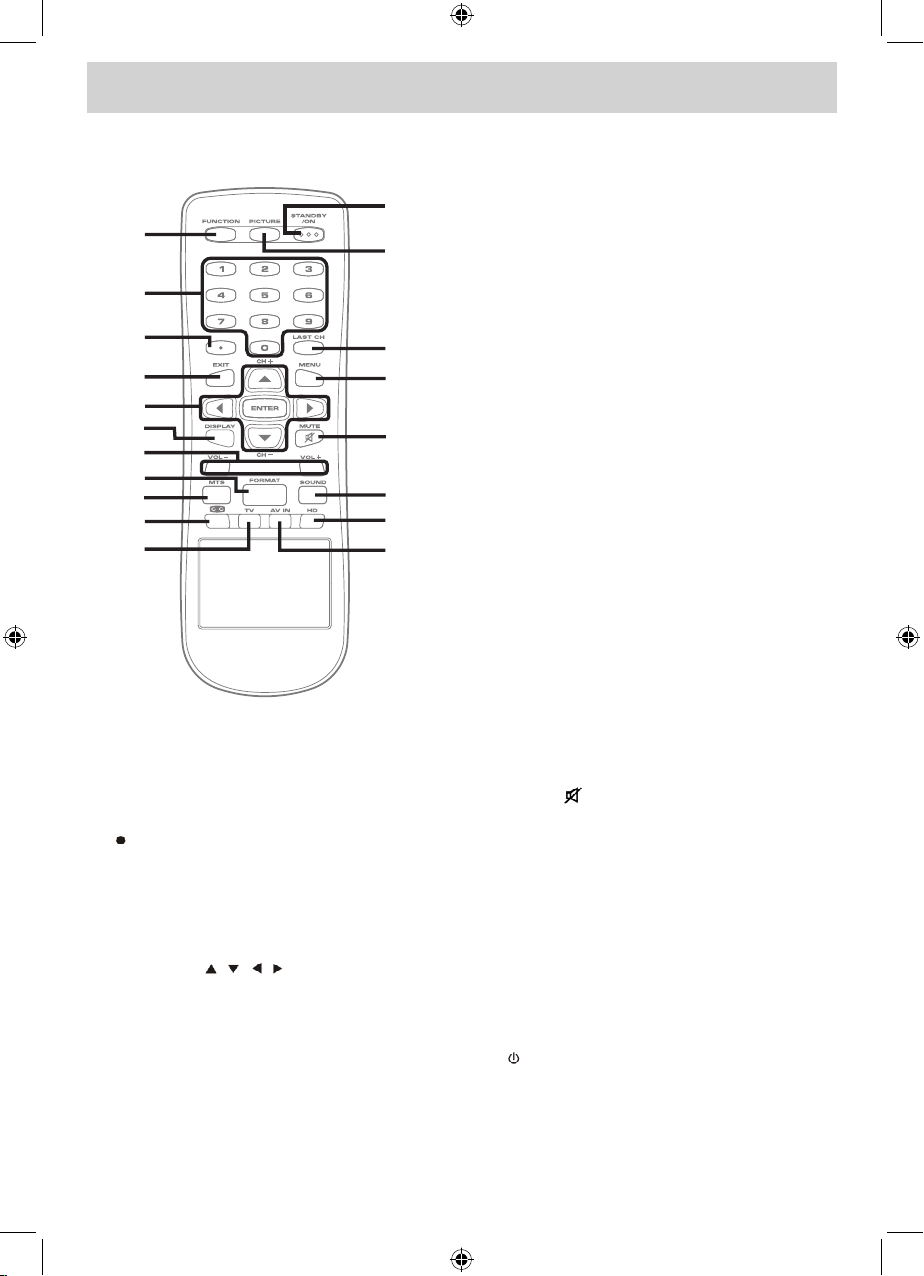
REMOTE CONTROL
1. FUNCTION Button
Press to switch between TV / AV In / YUV
In / PC In.
2. Number (0 - 9) Buttons
3. [dot] Button
Press to enter digital sub-channels (i.e.
11.3 or 12.7)
4. EXIT Button
Press to exit the TV SETUP menu and
return directly to normal viewing.
5. CURSOR ( , , , ) Buttons
Press to highlight selections on a menu
screen and adjust certain settings.
ENTER Button
Press to conrm selections on a menu
screen.
CH + / CH - Buttons
Press to change the TV channels.
6. DISPLAY Button
Press to show that input you are watching
(TV / AV in / YUV in / PC).
7. VOLUME (- / +) Buttons
Press to adjust the volume level.
8. FORMAT Button
Press to select the picture format (Auto,
4:3, Wide, Zoom).
9. MTS Button
Press to select between MONO sound,
STEREO sound and Secondary Audio
Program (SAP).
10. CC Button
Press to activate the Closed Captioning
feature. This function only wor ks on
programs broadcasted with captions.
11. TV Button
Press to switch to TV mode.
12. AV IN Button
Press to switch to source connected to AV
(composite) inputs.
13. HD Button
Press to switch to source connected to
YUV in (component) inputs.
14. SOUND Button
Press to select from preset sound settings
to match the type of show you are watching
(Standard / Music / Movie / Personal).
15. MUTE Button
Press to turn off the sound.
16. MENU Button
Press to display the on-screen TV menu.
17. LAST CH Button
Press to switch repeatedly between the
last two channels displayed.
18. PICTURE Button
Press to select from preset screen display
settings to match the type of show you
are watching (Standard / Soft / Movie /
Personal).
19. STANDBY / ON Button
Press to turn ON the unit or put it in
STANDBY (OFF) mode.
1
2
3
4
5
6
7
8
9
10
11
12
13
14
15
16
17
18
19
PLV36199.indd 5 8/28/2007 3:15:07 PM
Page 7
E - 6
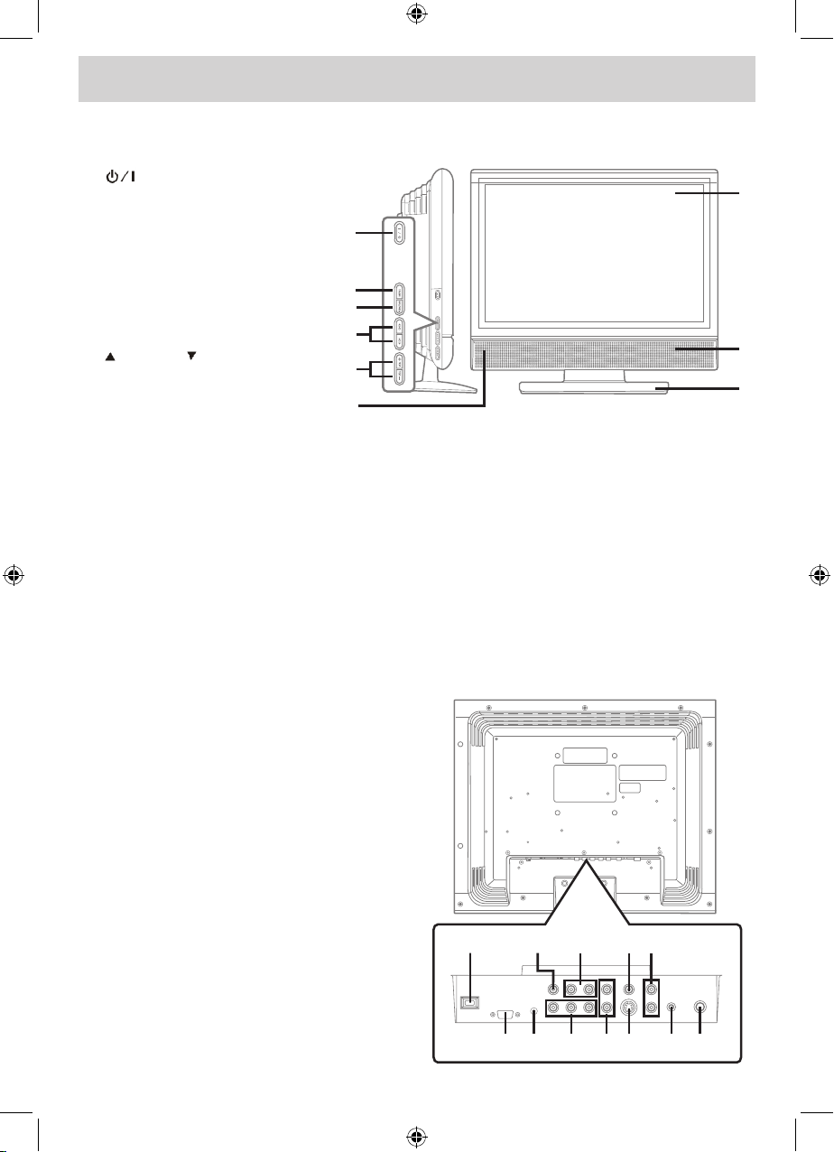
CONTROL REFERENCE GUIDE
FRONT AND SIDE VIEWS
1. Button
Press to turn the unit on and
off.
2. MENU Button
Press to enter the on-screen
TV menu.
3. FUNCTION Button
Press to select TV / AV in / YUV
in / PC in.
4. CH / CH Buttons
Press to select a TV channel
and hi g h light s s e lecti o n s
(Up and Down) on the menu
screen.
5. - VOL + Buttons
Press to adjust the volume level.
6. Remote Sensor
Receives the remote control signal.
Standby Indicator
7. Color LCD Screen
8. Speakers
9. Removable Stand
10. AC Power Cord
11. VIDEO OUT Jack
12. AUDIO OUT (Left / Right) Jacks
13. VIDEO IN Jack (AV IN)
14. AUDIO IN (Left/Right) Jacks (AV IN)
15. MONITOR / VGA Jack (PC IN)
16. AUDIO Jack (PC IN)
17. COMPONENT VIDEO IN (Y / PB / PR)
Jacks (YUV IN)
18. AUDIO IN (Left / Right) Jacks (YUV IN)
19. S-VIDEO IN Jack
20. HEADPHONES Jack
21. TV ANTENNA Terminal
REAR VIEW
7
1
2
3
4
6
5
8
9
10 11 12 13
15 16 17 18 19 21
14
20
PLV36199.indd 6 8/28/2007 3:15:09 PM
Page 8

E - 7
VCR/CAMCORDER /
SATELLITE SYSTEM /
CABLE, etc.
AV IN
TV
ANTENNA
CONNECTIONS
CONNECTING A TV ANTENNA / CABLE / SATELLITE
To view television channels correctly, a signal must be received from one of the following sources:
- An indoor or outdoor aerial antenna
- A cable system
- A satellite system
CONNECTING AN A/V DEVICE
To connect to other equipment such as a VCR, camcorder, satellite system or cable, etc.
NOTE
Please refer to the user manual
for the other equipment for more
information.
To AUDIO
IN jacks
(AV IN)
To S-VIDEO
IN jack
Conne c t ing a Dig i t al
Antenna
The tuner in this TV receives ATSC
TV signals from an antenna.
Th i s dig i t a l TV can receiv e
stan d a r d ( SD T V) an d h ig h
definition (HDTV) over the air
broadcasts.
Connecting an Analog
Antenna or Device
The tuner in this TV receives
NTSC TV signals, analog cable
signals or the RF output from a
satellite receiver, VCR or cable
box.
To S-VIDEO OUT /
AUDIO OUT jacks
Satellite, cable or TV
antenna cable to TV
ANTENNA terminal
(cable not included)
Connecting to a VCR /
Ca m corder / S atellite
System / Cable
Connect the AUDIO and S-VIDEO
cable (not included) as shown.
Make sure you connect the cable
from the other equipment (AUDIO
OUT and S-VIDEO OUT) to this
unit (AUDIO IN and S-VIDEO
IN).
PLV36199.indd 7 8/28/2007 3:15:23 PM
Page 9

E - 8
VCR/PVR /
CAMCORDER, etc.
VCR/VIDEO GAME
SYSTEM/
CAMCORDER, etc.
AV IN
CONNECTIONS
CONNECTING DEVICES WITH A COMPOSITE (YELLOW RCA-TYPE) VIDEO
OUTPUT
To connect A/V devices such as a VCR, video game system or camcorder.
Connecting to a VCR / Video Game System / Camcorder
Connect the AUDIO / VIDEO cable (not included) as shown.
Make sure you connect the cable from the other equipment (AUDIO and VIDEO OUT) to this unit (AUDIO
and VIDEO IN).
NOTE
Please refer to the user manual for the other equipment for more information.
To AUDIO
/ VIDEO IN
jacks
(AV IN)
To AUDIO / VIDEO
OUT jacks
CONNECTING DEVICES WITH A COMPOSITE (YELLOW RCA-TYPE) VIDEO
INPUT
To connect A/V devices such as a VCR, PVR or camcorder.
Connecting to a VCR /
PVR / Camcorder
Connect the AUDIO / VIDEO
cable (not included) as shown.
Ma ke su re yo u con nect the
cable from the other equipment
(AUDIO and VIDEO IN) to this
unit (AUDIO and VIDEO OUT).
NOTE
Please refer to the user manual
for the other equipment for more
information.
To AUDIO
/ VIDEO
OUT jacks
To AUDIO / VIDEO IN jacks
PLV36199.indd 8 8/28/2007 3:15:32 PM
Page 10

E - 9
HD SOURCE
With component video output
(Digital Cable Box*, Satellite
Receiver*, or external
over-the-air HD-Tuner).
COMPONENT
VIDEO IN
COMPONENT
VIDEO OUT
CONNECTIONS
CONNECTING A HIGH-DEFINITION (HD) SOURCE
High-Denition (HD) Devices with component video output must be connected to the YUV input.
Connect the component video cable and audio cable (not included) as shown.
Make sure you connect the component video cable and audio cable from the other equipment (COMPONENT
VIDEO OUT and AUDIO OUT) to this unit (COMPONENT VIDEO IN and AUDIO IN - YUV IN).
NOTE
When connecting a DVD player to the television, the picture resolution is solely dependent upon the resolution
supported by the DVD player attached. DVD player resolutions vary from 480i to 1080i, and this unit can
support DVD players up to a maximum resolution of 1080i.
To AUDIO
IN jacks
(YUV IN)
To AUDIO
OUT jacks
To COMPONENT
VIDEO IN jacks
(YUV IN)
To COMPONENT
VIDEO OUT jacks
* May require a subscription
for receiving HD channels.
Check with your cable/
satellite service provider for
details.
CONNECTING A PC
Connect the 15-pin D-SUB PC/VGA connector from your computer to the 15-pin D-SUB PC/VGA input on
this unit using a monitor cable and an audio cable (not included) as shown.
Ma ke su re yo u con nect the
cable from the computer (PC
Connector and AUDIO - PC
OUT) to this unit (MONITOR /
VGA and AUDIO - PC IN).
To AUDIO jack (PC OUT)
To PC connector
PLV36199.indd 9 8/28/2007 3:15:42 PM
Page 11
E - 10
AUDIO AMPLIFIER /
EXTERNAL SPEAKERS
USING HEADPHONES
• Turn down the volume before
connecting headphones to the
unit, then adjust the volume to
your desired level.
• W h e n h e a d p h o n e s a re
connected, no sound will come
from the front speakers.
NOTE
Avoid listening to sound at high
levels for prolonged periods of
time. This may be harmful to you
and may cause hearing loss.
Headphones
(1/8” [3.5mm]
diameter plug)
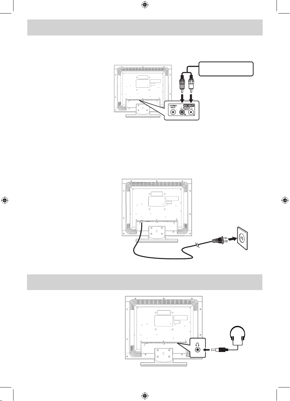
CONNECTIONS
CONNECTING AN AUDIO AMPLIFIER
This connection allows you to use an audio amplier and external speakers.
Connect the AUDIO cable (not
included) as shown.
Ma ke su re yo u con nect the
cable from the other equipment
(AUDIO IN) to this unit (AUDIO
OUT).
To AUDIO
OUT jacks
To AUDIO IN jacks
CONNECTING THE AC POWER CORD
• Connect the AC power cord into a wall outlet.
• Press the STANDBY / ON button on the left side of the unit or use the remote control to turn on the
unit.
NOTES
• TOPREVENTELECTRICSHOCK,MATCHWIDEBLADEOFPLUGTOWIDESLOTOFWALLOUTLET,
THEN FULLY INSERT.
To AC
wall outlet
• When the AC power cord is
plugged in, the unit is not
completely disconnected from
the main power, even when
the power is turned off.
• Be sure the AC power cord
is d isc o n n ect e d an d a l l
functions are off before making
connections.
• Make sure all components are
connected correctly.
• When you are not going to use
the unit for a long period of
time, disconnect the AC power
cord.
PLV36199.indd 10 8/28/2007 3:15:43 PM
Page 12

E - 11
INSTALLATION
MOUNTING ON THE WALL
This unit is VESA-compliant, and is designed to be wall-mounted with a VESA-compliant 3 15/16” x 3 15/16”
(100mm x 100mm) mounting kit designed for at-panel TVs (sold separately). Mount this unit according to
the directions included with the mounting kit.
REMOVING THE BASE STAND
WARNING: The LCD Display is very fragile, and must be protected at all times when removing the base
stand. Be sure that no hard or sharp object, or anything that could scratch or damage the LCD display,
comes into contact with it. Do NOT place pressure on the front of the unit at any time because the screen
could crack.
1. Disconnect any cables or cords connected to the unit.
2. Lay the unit down on a at surface, so the backside is facing up, making sure to place a soft cushioned
material (such as a pillow or thick piece of foam) beneath the screen.
3. Remove the four screws and then remove the BASE STAND from the TV.
3 15/16”
3 15/16”
Four mounting
holes
PLV36199.indd 11 8/28/2007 3:15:44 PM
Page 13

E - 12
TV SETUP
PICTURE MENU
1. Press the MENU button.
2. Press the button to enter PICTURE settings.
3. Use the or button to select the options (Picture
Mode, Contrast, Brightness, Sharpness, Tint or
Color). Adjust them using the or button (Screen
will change to your desired setting).
4. Repeat step 3 to adjust other options.
5. To exit the MAIN MENU and return to the normal screen,
press the EXIT or MENU button repeatedly.
Note: Some setting items on the menu screen may not activate depending on what mode the unit is
currently in (TV/AV in/YUV in/PC in).
Picture Mode : Select from preset screen display settings to match the type of show you are watching
(Standard, Soft, Movie and Personal). Select Personal mode to recall your custom settings
on contrast, brightness, sharpness tint and color.
Contrast : Adjust to sharpen the picture quality. The black portions of the picture become richer in
darkness and the white become brighter.
Brightness : Adjust the brightness of the picture. Brighten or darken the whole picture.
Sharpness : Adjust the sharpness level to improve detail in the picture.
Tint : Adjust the tint of the picture. (toward purple / toward green)
Color : Adjust the color of the picture.
AUDIO MENU
1. Press the MENU button.
2. Use the or button to select AUDIO, then press the
button to enter the AUDIO settings.
3. Use the or button to select the options (Sound
Mode, Bass, Treble, Balance, Audio Language or
MTS). Adjust them using the or button.
4. Repeat step 3 to adjust other options.
5. To exit the MAIN MENU and return to the normal screen,
press the EXIT or MENU button repeatedly.
Sound Mode : Select from preset sound settings (Standard, Music, Movie or Personal) to match the
type of show you are watching. Select Personal mode to recall your custom settings
on bass, treble and balance.
Bass : Adjust the bass range.
Treble : Adjust the treble range.
Balance : Adjust the balance level toward the left or right speakers.
Audio Language : Select from English / Spanish / French. (Available for digital channels if multiple audio
languages are broadcasted.)
MTS (Multi Channel Television Sound) : Select Stereo / SAP (Secondary Audio Program) / Mono.
Note: Experiment with different sound settings until
youndthesettingsyouprefer.
Note:
The SAP (Secondary Audio Programs) feature allows a TV station to broadcast other information, which
could be audio in another language.
PICTURE AUDIO TIME SETUP PARENTAL TV
PictureMode
Contrast
Brightness
Sharpness
Tint
Color
63
44
25
0
60
Standard
UP/DOWN ADJUST
"MENU":EXIT
PICTURE AUDIO TIME SETUP PARENTAL TV
Sound Mode
Bass
Treble
Balance
Audio Languag e
MTS
50
50
0
Standard
UP/DOWN ADJUST
"MENU":EXIT
English
Stereo
PLV36199.indd 12 8/28/2007 3:15:48 PM
Page 14
E - 13
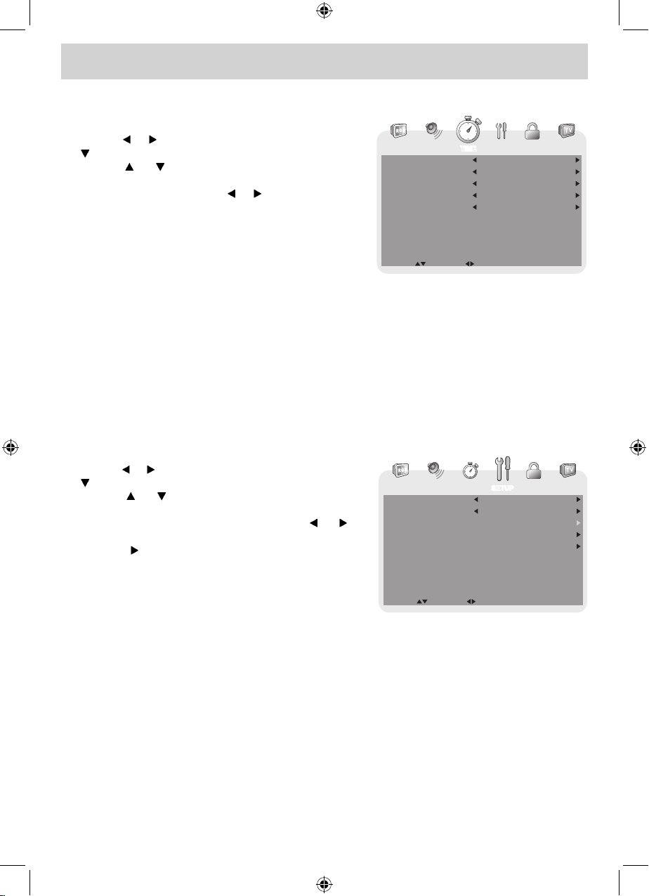
TV SETUP
TIME MENU
1. Press the MENU button.
2. Use the or button to select TIME, then press the
button to enter the TIME settings.
3. Use the or button to select the options (OSD
Duration, Sleep Timer, Time Zone or Day Saving
Time). Adjust them using the or button.
4. Repeat step 3 to adjust other options.
5. To exit the MAIN MENU and return to the normal
screen, press the EXIT or MENU button repeatedly.
OSD (On Screen Display) Duration : Select the length of time for the On screen menu is displayed : 15
Sec / 30 Sec / 45 Sec / 60 Sec.
Sleep Timer : Select the length of time before the unit automatically changes to Standby mode : Off
-> 5 Minutes -> 10 Minutes -> 15 Minutes -> 30 Minutes -> 60 Minutes -> 90 Minutes
-> 120 Minutes -> Off.
Time Zone : Select the time zone from Eastern / Central / Mountain / Pacic / Alaska / Hawaii.
Day Saving Time : Select On to activate daylight savings time.
Clock : Display the current time.
SETUP MENU
1. Press the MENU button.
2. Use the or button to select SETUP, then press the
button to enter the SET UP settings.
3. Use the or button to select the options (OSD
Language, Color Mode, PC SetUp, Closed Caption
or Restore Setting). Adjust them using the or
button (Screen will change to your desired setting); or
press the button to go into the detailed settings.
4. Press the MENU button to return to the previous
menu.
5. Repeat steps 3 and 4 to adjust other options.
6. To exit the MAIN MENU and return to the normal screen,
press the EXIT or MENU button repeatedly.
OSD (On Screen Display) Language : Select On-screen menu language from English / French /
Spanish.
Color Mode : Adjust the three color temperature of the picture. Choose from Normal (balanced),
Warm (red white), or Cool (blue white) modes.
Restore Setting : If you reset the TV to the factory settings, all your present settings on PICTURE and
AUDIO will be erased and replaced by the factory’s default settings.
PICTURE AUDIO TIME SETUP PARENTAL TV
OSDDuration
Sleep Timer
Time Zone
DaySavingTime
Clock
15 Sec
Off
Eastern
Off
2007/03/05 04:39PM
UP/DOWN ADJUST
"MENU":EXIT
PICTURE AUDIO TIME SETUP PARENTAL TV
OSD Language
ColorMode
Closed Caption
Restore Setting
PC Set Up
English
Normal
UP/DOWN ADJUST
"MENU":EXIT
PLV36199.indd 13 8/28/2007 3:15:52 PM
Page 15

E - 14
TV SETUP
PC Set Up (in PC mode only)
- Resolution : 1,440 x 900 max
- Refresh Frequency : 60Hz max
H - Pos : Center the image by moving it left or right.
V - Pos : Center the image by moving it up or down.
Clock : Adjusts the display clock to change width of
the image.
Phase : Adjusts the image if there is icker of screen
letters, color misalignment, or blurring.
Closed Caption
CC Mode : Select closed caption On, Off or CC on Mute.
Analog Closed Caption : Select the analog closed caption or turn it off.
Digital Closed Caption : Select the digital closed caption or turn it off.
Digital Caption Style : Select as Broadcaster to use the default digital caption style of the broadcaster.
Select Custom to activate the caption style items and set your desired detailed
settings.
Note:
This function only works on ATSC
programs broadcast with captions.
PARENTAL MENU
Password
1. Press the MENU button.
2. Use the or button to select PARENTAL, then
press the button to enter the PARENTAL settings.
The menu locked screen will be displayed.
3. Enter a 4-digit password. Once entered, the screen
will enter the Parental menu. The preset password is
0000.
If you forget the password,
enter “ 8888 “ to unlock parental
control.
PICTURE AUDIO TIME SETUP
H-Pos
V-Pos
Clock
Phase
Auto adjust
UP/DOWN ADJUST
"MENU":EXIT
50
50
50
100
Best Resolutionis 1440x900
PICTURE AUDIO TIME SETUP PARENTAL TV
CC Mode
Analog Closed Caption
Digital Closed Caption
DigitalCaptionStyl e
CC on Mute
CC1
Service1
UP/DOWN ADJUST
"MENU":EXIT
PICTURE AUDIO TIME SETUP PARENTAL TV
Enter Password
UP/DOWN ADJUST
"MENU":EXIT
PLV36199.indd 14 8/28/2007 3:15:57 PM
Page 16

E - 15
TV SETUP
Rating Enable : Select On to edit the following parental items. Select Off to disable parental control.
US : Set TV and MPAA ratings.
Canada : Set Canada English and Canada French ratings.
RRT Setting : Set Rating Region Table.
Reset RRT : Reset Rating Region Table to the default settings.
Parental
1. Use the or button to select various Parental settings.
Adjust them using the or button, or press the button
to go into the detailed settings.
2. Press the MENU button to return to the previous menu.
3. Repeat steps 1 - 2 to adjust other options.
4. To exit the MAIN MENU and return to the normal screen,
press the EXIT or MENU button repeatedly.
TV-Y : Recommended for all children.
TV-Y7 : Recommended for all children age 7 and above.
TV-G : General Audience.
TV-PG : Parental Guidance Suggested.
TV-14 : Parental Strongly Cautioned.
TV-MA : Mature Audience Only.
N/A : Not rated.
G : GENERAL AUDIENCES, Suitable for all ages.
PG : PARENTAL GUIDANCE SUGGESTED - Some material may not be suitable for
children.
PG-13 : PARENTS STRONGLY CAUTIONED - Some material may be inappropriate for
children under 13.
R : RESTRICTED, Under 17 requires accompanying parent or adult guardian for
viewing in movie theaters.
NC-17 : No one 17 or under admitted in movie theaters,
X : Adults Only.
E : Exempt.
C : Children.
C8+ : Recommended for children age 8 and older.
G : GENERAL AUDIENCES, Suitable for all ages.
PG : PARENTAL GUIDANCE SUGGESTED - Some material may not be suitable for
children.
14+ : Viewers 14 years and older.
18+ : Adult Programming.
E : Exempt.
G : GENERAL AUDIENCES, Suitable for all ages.
8 ans+ : Not recommended for young children.
13 ans+ : Not suitable for children under the age of 13.
16 ans+ : Not suitable for children under the age of 16.
18 ans+ : Adult Programming.
U.S.
MPAA
Ratings
U.S. TV
Ratings
Canadian
English
Ratings
Canadian
French
Ratings
PICTURE AUDIO TIME SETUP PARENTAL TV
ChangePassword
Rating Enable
US
Canada
RRT Setting
Reset RRT
On
UP/DOWN ADJUST
"MENU":EXIT
PLV36199.indd 15 8/28/2007 3:16:00 PM
Page 17

E - 16
TV SETUP
Antenna : Air (over-the-air broadcasts, Ch 2-69) or CATV (cable/satellite broadcasts, CH 1-135)
mode are available.
Auto Scan : Search for usable stations and store them in memory.
Auto Scan Add CH : Search for more usable stations and add them in memory. The stations stored before
are still kept.
Channel Skip : Skip weak channels and the channels you don’t like.
Channel No. : Select a different TV channel.
Channel Label : Display and edit the channel label.
DTV Signal : Display the signal strength (for digital TV channels only).
TV MENU (For TV Mode Only)
1. Press the MENU button.
2. Use the or button to select TV, then press the
button to enter the TV settings.
3. Use the or button to select the options (Antenna,
Auto Scan, Auto Scan Add CH, Channel Skip,
Channel No. Channel Label or DTV Signal). Adjust
them using the or button, or press the button
to go into the detailed settings.
4. Press the MENU button to return to the previous
menu.
5. Repeat steps 3 and 4 to adjust other options.
6. To exit the MAIN MENU and return to the normal
screen, press the EXIT or MENU button repeatedly.
Channel Skip
1. Use the or button to select a channel. (Press the
button to select the last channel of the page; press
again to go to the next page. Press the button to
select the rst channel of the page; press again to
return to the previous page.)
2. Press the ENTER button to shift between On / Off.
(Select On to skip the selected channel. The channel
will not appear when you press the CH / CH
button.)
PICTURE AUDIO TIME SETUP PARENT AL TV
Antenna
Auto Scan
Auto Scan AddCH
Channel Skip
Channel No.
Channel Label
DTVSignal
Air
5-5
XXX
UP/DOWN ADJUST
"MENU":EXIT
Good
PICTURE AUDIO TIME SETUP PARENT AL TV
"MENU":EXIT"ENTER":SELECT
Skip
On
On
Off
Off
Off
On
Off
No.
3
2
4
5
5-1
6
7
Program Name
XXXX
XXX
XX
XX
XXXX
XXXXX
XXXX
NEXT
PICTURE AUDIO TIME SETUP PAREN TAL TV
EDIT SELECT
"MENU":EXIT
X
Channel Label
You can edit a label for each channel.
1. Use the or button to select the number or letter.
Use the or button to move and edit the next
character.
2. After editing, the Channel and Channel Label will be
shown on the screen when you press the DISPLAY
button.
PLV36199.indd 16 8/28/2007 3:16:05 PM
Page 18

E - 17
MAINTENANCE
CLEANING THE UNIT
• Be sure to turn the unit off and disconnect the AC power cord before cleaning the unit.
• Wipe the unit with a dry soft cloth. If the surfaces are extremely dirty, wipe clean with a cloth that has been
dipped in a weak soap-and-water solution and wrung out thoroughly. Then wipe it with a dry cloth.
• Never use alcohol, benzene, paint-thinner, cleaning uid or other chemicals. Do NOT use compressed
air to remove dust.
TROUBLESHOOTING GUIDE
SYMPTOM CAUSE (AND REMEDY)
The remote does not
function.
• Make sure the AC power cord is connected.
• The unit is not turned on.
No power.
• Remove any obstacles between the remote and the unit.
• Use the remote near the unit.
• Point the remote at the remote sensor on the unit.
• Replace the batteries in the remote with new ones.
• Check the location of the antenna and adjust it if necessary.
• Make sure the antenna cable is rmly connected.
• Make sure all input cables are rmly connected.
TV
Bad Picture (snow,
m u lt i pe i ma g es ,
distortion, blurry)
• Check the PICTURE MENU within the TV SETUP MENU.
• Check to make sure the program you are watching is broadcast in Color and
not black and white.
Bl a c k a nd w h it e
picture.
• Make sure the unit is plugged in and turned on.
• Make sure TV mode is selected.
• Try a new channel to check for possible station trouble.
• Make sure the antenna is connected properly.
• Increase the volume.
• Make sure the antenna or audio video source device is working properly.
• Make sure all cables are rmly connected.
• Check for local interference.
No picture or sound.
• Make sure there are no unshielded electrical devices nearby that are causing
interference.
• Turn the unit off for 30 minutes, then try it again.
Colored patches of
picture.
PLV36199.indd 17 8/28/2007 3:16:06 PM
Page 19

E - 18
Unit : INCH
11
18 4
6 5/ 8
16 5 / 8
7
10 15/16
8 5/ 8
12 ½
14 7 / 8
PLV36199.indd 18 8/28/2007 3:16:07 PM
Page 20

E - 19
© 2007 Venturer Electronics Inc.
VENTURER ELECTRONICS (“VENTURER”) makes the following limited warranty. This limited warranty extend to
the original consumer purchaser and is limited to non-commercial use of the product.
Ninety (90) Day Parts & Labor Warranty
VENTURER products purchased in the United States are warranted to be free from defects in materials or workmanship for
a period of ninety (90) days from the date of their original retail purchase. If the unit fails to conform to this warranty, we will
service the product using new or refurbished parts and products, at VENTURER’s sole discretion.
During a period of ninety (90) days from the effective warranty date, Venturer will provide, when needed, service labor to
repair a manufacturing defect at its designated Service Center. To obtain warranty service in the Untied States, you must first
call our Customer Support Center at (800) 252-6123, during the hours listed in the box below. The determination of
service will be made by VENTURER Customer Support. PLEASE DO NOT RETURN YOUR UNIT TO VENTURER
WITHOUT PRIOR AUTHORIZATION. New or remanufactured replacements for defective parts or products will be used
for repairs by Venturer at its designated Service Center for ninety (90) days from the effective warranty date. Such replacement
parts or products are warranted for an additional ninety (90) days from the date of repair or replacement. The Customer will
be required to ship the unit to the Service Center indicated at the time Customer Support is contacted to make the necessary
repairs. The customer is responsible for all transportation charges to the service facility.
Packaging and Shipping Instruction
When you send the product to the Venturer service facility you must use the original carton box and packing material or an
equivalent as designated by VENTURER.
LIMITED WARRANTY
Your Responsibility
(1) You must retain the original sale receipt to provide proof of purchase.
(2) These warranties are effective only if the product is purchased and operated in the U.S.A. or Canada.
(3) Warranties extend only to defects in material or workmanship, and do not extend to any product or parts which have been
lost or discarded, or damage to product or parts caused by misuse, accident, improper operation or maintenance, or use in
violation of instructions provided with the product, or to product which has been altered or modified without authorization
of VENTURER, or to products or parts thereof which have had the serial number removed or changed.
Out of Warranty
In the event your product requires repair after the limited warranty period has expired, please contact our Customer
Support Center at 1-800-252-6123 or www.venturer.com.
Hours: Monday–Thursday: 9–7, Friday: 9–5, Saturday: 9–12 EST.
Important:
You are responsible for any transportation, shipping or insurance relative to the return of product to our Product Returns
Center.
All warranties implied by state law, including the implied warranties of merchantability and fitness for a particular purpose,
are expressly limited to the duration of the limited warranties set forth above. With the exception of any warranties implied
by state law as hereby limited, the foregoing warranty is exclusive and in lieu of all other warranties, guarantees, agreements
and similar obligations of manufacturer or seller with respect to the repair or replacement of any parts. In no event shall
VENTURER be liable for consequential or incidental damages.
No person, agent, distributor, dealer or company is authorized to change, modify or extend the terms of these warranties in
any manner whatsoever. The time within action must be commenced to enforce any obligation of VENTURER arising under
the warranty or under any statute, or law of the United States or any state thereof, is hereby limited to ninety (90) days from
the date of purchase. This limitation does not apply to implied warranties arising under state law.
This warranty gives you specific legal rights and you may also have other rights, which may vary, from state to state. Some
states do not allow limitation on how long an implied warranty lasts, when an action may be brought, or the exclusion or
limitation of incidental or consequential damages, so the above provisions may not apply to you.
Printed in China
811-361991W230
For more information on other products and services, please visit our web site at www.venturer.com
Important: Also keep your “Bill of Sale” as proof of purchase.
Model no. ............................................................. Product name....................................................................................
Type of set ..........................................................................................................................................................................
Serial no. ............................................................. Invoice no. ........................................................................................
Date purchased ..................................................... Dealer name .....................................................................................
PLV36199.indd 19 8/28/2007 3:16:07 PM
 Loading...