

Page 1
PDV28420C
42" Plasma TV
Owner's Manual
811-284291W021
Printed in China
Page 2
CAUTION
• DANGER OF EXPLOSION IF BATTERY IS INCORRECTLY
RE PL ACED. RE PL ACE ON LY WIT H T HE SAME OR
EQUIVALENT TYPE.
• TO PREVENT ELECTRIC SHOCK, MATCH WIDE
BLADE OF PLUG TO WIDE SLOT OF WALL OUTLET,
THEN FULLY INSERT.
• US E OF CO NT R OL S OR A DJ U ST M EN T S O R
PE RFO RMANC E OF PROC EDU RES OTH ER THA N
TH OS E SPEC IF IED MAY RE SULT IN HA ZARDOUS
RADIATION EXPOSURE.
WARNING :
• TO PREVENT FI RE OR SHOCK HA ZA RD, DO NOT
EXPOSE THIS UNIT TO RAIN OR MOISTURE. DO NOT
PLACE OBJECTS FILLED WITH LIQUIDS ON OR NEAR
THIS UNIT.
• SHOULD ANY TROUBLE OCCUR, DISCONNECT THE
AC POWER CO RD AN D RE FER S ERVI CI NG TO A
QUALIFIED TECHNICIAN.
WARNING: Changes or modificati ons to this unit
not expressly app rove d by pa rty re sp onsible for
compliance could void the user authority to operate
the unit.
PLACEMENT INFORMATION
• Do not use this unit in places which are extremely
hot, cold, dusty or humid.
• Do not restrict the air ow of this unit by placing it
somewhere with poor air ow, by covering it with a
cloth, or by placing it on bedding or carpeting.
SAFETY INFORMATION
• When connec ting or disconnecting the AC power
cord, grip the plug and not the cord itself. Pulling the
cord may damage it and create a hazard.
• When you are not going to use the unit for a long
period of time, disconnect the AC power cord.
CONDENSATION INFORMATION
• When left in a heated room where it is warm and
damp, water droplets or condensation may form
inside the equipment. When there is condensation
inside the unit, the unit may not function normally.
Let the unit stand for 1-2 hours before turning the
power on or gradually heat the room and allow the
unit to dry before use.
RATING PLATE LOCATION
The rating plate is located on the rear of the unit.
FCC STATEMENTS
NOTE: This unit has been tested and found to comply
with the limits for a Class B digital device, pursuant
to Part 15 of the FCC Rules. These limits are designed
to provid e reas onable protec tion against harmful
inter feren ce in a residential installation. This unit
generates, uses and can radiate radio frequency energy
and, if not installed and used in accordance with the
instructions, may cause harmful interference to radio
communication. However, there is no guarantee that
interference will not occur in a particular installation.
If this unit does cause harmful interference to radio
or television reception, which can be determined by
turning the unit o and on, the user is encouraged to
try to correct the interference by one or more of the
following measures:
- Reorient or relocate the receiving antenna.
- Increa se the separati on b et ween the unit and
receiver.
- Connect the unit into an outlet on a circuit dierent
from that to which the receiver is connected.
- Con sult the de al er or an experienced radio /T V
technician for help.
WARNING : TO REDUCE THE RISK OF ELECTRIC
SHO CK, DO NOT REMOVE COVER (OR BACK).
NO USERSERVICEABLE PARTS INSIDE. RE FER
SERVICING TO QUALIFIED SERVICE PERSONNEL.
The exclamation point within an equilateral
tr ia ngle is inte nd ed to aler t the user to
the presence of important operating and
maintenance (servicing) instructions in the literature
accompanying the appliance.
The lightning flash with arrowhead symbol,
within an equilateral triangle, is intended to
alert the user to the presence of uninsulated
“dangerous voltage” within the product’s enclosure
that may be of sucient magnitude to constitute a risk
of electric shock to persons.
SAFETY PRECAUTIONS
E-1
Page 3

IMPORTANT SAFETY INSTRUCTIONS
E-2
1) Read these instructions.
2) Keep these instructions.
3) Heed all warnings.
4) Follow all instructions.
5) Do not use this apparatus near water.
6) Clean only with a dry cloth.
7) Do not block any ventilation openings.
I n s t a l l i n a c c o r d a n c e w i t h t h e
manufacturer’s instructions.
8) Do not install near any heat sources such
as radiators, heat registers, stoves or other
ap parat us (Includ ing amp lif iers) that
produce heat.
9) Do not defect the safety purpose of the
pol ariz ed or gro undi ng- type pl ug. A
polarized plug has two blades with one
wider than the other. A grounding type
plug has two blades and a third grounding
prong. The wide blade or the third prong
is provided for your safety. If the provided
plug does not fit into your wall outlet,
consult an electrician for replacement of
the obsolete outlet.
10) Protect the AC power cord from being
wa lke d on or p inch ed pa rtic ula rly at
plugs, convenience receptacles and the
point where they exit from the apparatus.
11) On l y use attachments / acces so ri es
specied by the manufacturer.
12) Use on ly wit h a ca rt , stand, tripod,
bracket, or table specified by
the manufac tu rer, or sold
with the apparatus. When a
cart is used, use caution when
movi ng the cart / app aratus
combination to avoid injury from tip-over.
13) Unplug this apparatus during lightning
storms or when unused for long periods of
time.
14) Refer all servicing to qualified ser vice
personnel. Servicing is required when
the apparatus has been damaged in any
way, such as the AC power cord or plug
is damaged, liquid has spilled or objects
have fa llen int o the appa ratu s, or the
apparatus has been exposed to rain or
moisture, does not operate normally, or
has been dropped.
Page 4

E-3
CONTENTS
SAFETY PRECAUTIONS ..................................................................................................... 1
IMPORTANT SAFETY INSTRUCTIONS ............................................................................... 2
QUICK INSTALLATION ..................................................................................................................... 4
ACCESSORIES ..................................................................................................................... 5
GETTING STARTED ............................................................................................................ 5
CONTROL REFERENCE GUIDE ...................................................................................... 6 - 8
CONNECTIONS ........................................................................................................................... 9 - 13
Connecting a Antenna / Cable / Satellite ....................................................................................................................................9
Connecting an A / V Device .................................................................................................................................................................. 9
Connecting Devices with a Composite (Yellow RCA-Type) Video Output ........................................................................ 10
Connecting Devices with a Composite (Yellow RCA-Type) Video Input ........................................................................... 10
Connecting a High Denition (HD) Source Using HDMI Connection ................................................................................... 11
Connecting a High Denition (HD) Source Using Component Connection .................................................................... 11
Connecting a PC ..................................................................................................................................................................................... 12
Connecting an Audio Amplier ............................................................................................................................................... 12
Connecting the AC Power Cord ..................................................................................................................................................... 13
USING HEADPHONES ...................................................................................................... 13
INSTALLATION ................................................................................................................................. 14
Installing the Base Stand ................................................................................................................................................................... 14
Mounting on the Wall ..................................................................................................................................................................... 14
TV SETUP .................................................................................................................................. 15 - 21
Video Menu .............................................................................................................................................................................................. 15
Audio Menu ............................................................................................................................................................................................. 16
TV Menu .................................................................................................................................................................................................... 17
Setup Menu ..................................................................................................................................................................................... 18 - 19
Parental Menu ............................................................................................................................................................................. 20 - 21
TROUBLESHOOTING GUIDE ........................................................................................... 22
LIMITED WARRANTY ................................................................................................ 23-24
DIGITAL TELEVISION TRANSITION NOTICE .................................................................................... 25
Page 5
E-4
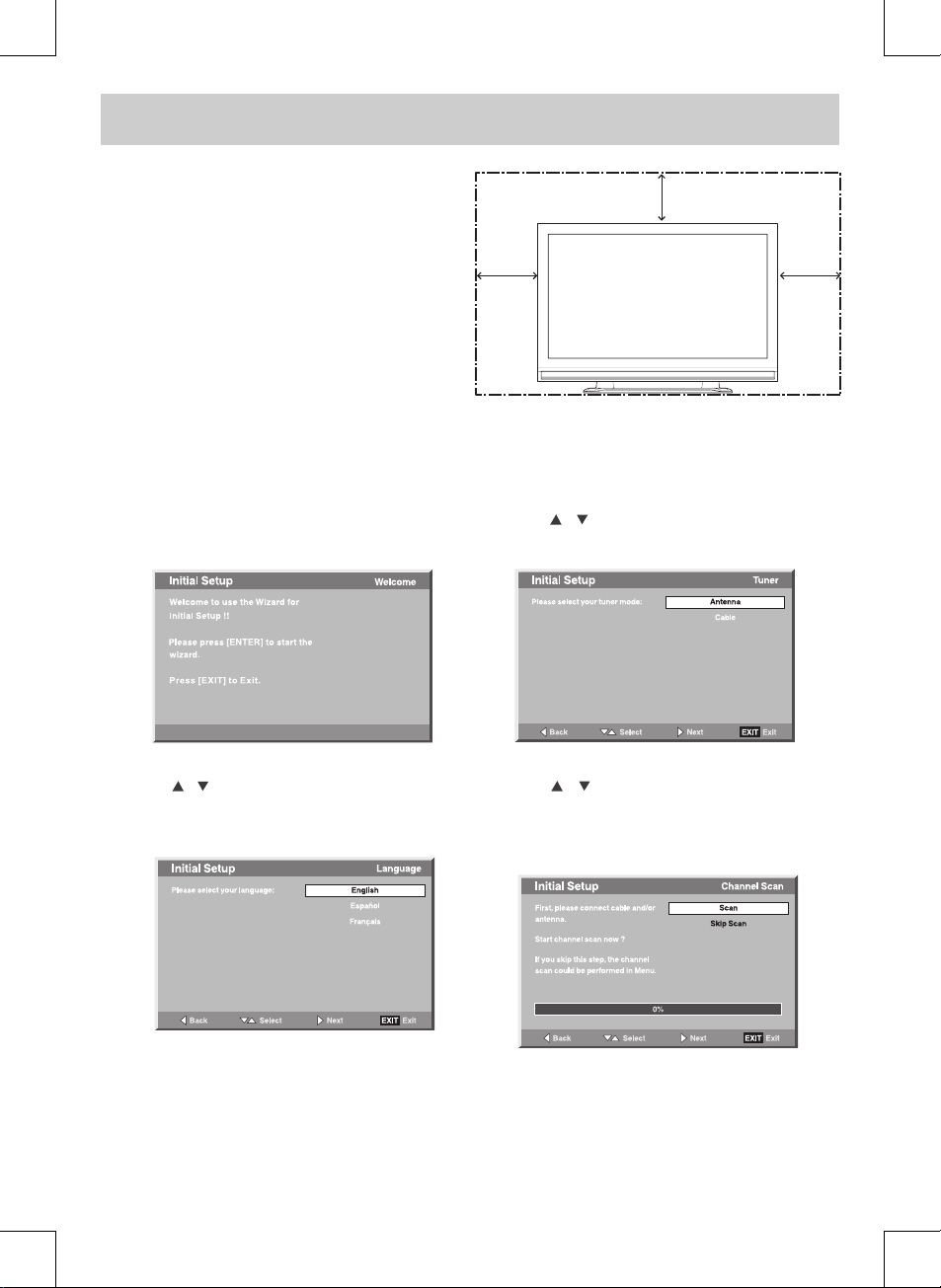
Whe n you turn on your tel evision set for the first
time, be sure to place it on a solid stable surface. To
avoid danger, do not expose the TV to water or a heat
source (e.g. lamp, candle, radiator). Do not obstruct
the ventilation grid at the rear and be sure to leave
sucient gaps around the unit as shown.
4"
4"
4"
TURNING THE UNIT ON FOR THE FIRST TIME
The rst time you turn the unit on, it will go directly to the setup mode. Simply follow the screen prompts as shown
below to tune in the channels.
1. When the screen appears as below, press the ENTER
button to start the wizard.
2. Use the
/ button to move to dierent language,
press the ENTER button to select the desired
language.
QUICK INSTALLATION
3. Use the / button to select the tuner mode and
press the ENTER button to conrm.
4. Use the / button to select the scan mode and
press the ENTER button to start scan. The system will
automatically start to scan and preset all available
stations.
5. After scanning has nished, the TV will display the
rst station stored.
Page 6
E-5
ACCESSORIES
Please check and identify the supplied accessories.
Remote Control (with batteries) ................................................................................................................................................ x 1
AC Power Cord ................................................................................................................................................................................. x 1
Screw for Base Stand ...................................................................................................................................................................... x 4
GETTING STARTED
USING THE REMOTE CONTROL
• Point the remote control at the remote sensor located on the unit.
• When there is a strong ambient light source, the performance of the infrared remote sensor may be degraded,
causing unreliable operation.
• The recommended eective distance for remote operation is about 16 feet (5 meters).
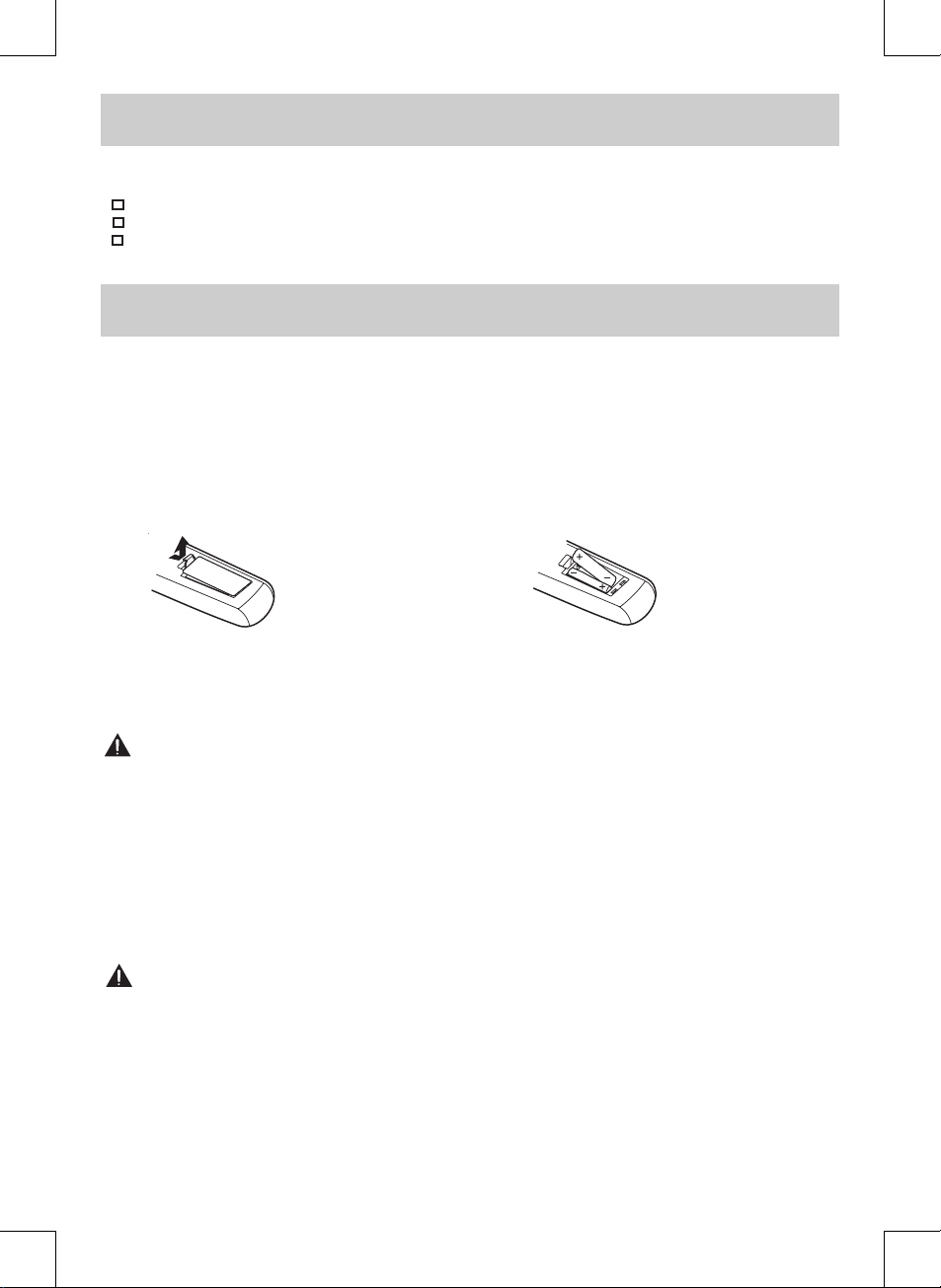
TO INSTALL BATTERIES
1. Open the battery door. 2. Insert 2 “AAA” batteries.
BATTERY REPLACEMENT
When the batteries become weak, the operating distance of the remote control is greatly reduced and you will
need to replace the batteries.
CAUTION:
Danger of explosion if battery is incorrectly replaced.
NOTES
• If the remote control is not going to be used for a long time, remove the batteries to avoid damage caused by
battery leakage corrosion.
• Do not mix old and new batteries. Do not mix ALKALINE, standard (CARBON-ZINC) or rechargeable (NICKELCADMIUM) batteries.
• Always remove batteries as soon as they become weak.
• Weak batteries can leak and severely damage the remote control.
• WARNING : Do not dispose of batteries in a re. Batteries may explode or leak.
WARNING : Battery shall not be exposed to excessive heat such as sunshine, re or the like.
Many universal remote controls have a “learning” feature. We recommend you use that feature to program the
remote control.
For any questions or problems related to programming a universal remote control, you must contact the
customer service department of the universal remote control manufacturer for assistance, or refer to the
instructions included with the universal remote control. We cannot oer assistance in programming universal
remote controls.
Page 7
CONTROL REFERENCE GUIDE
E-6
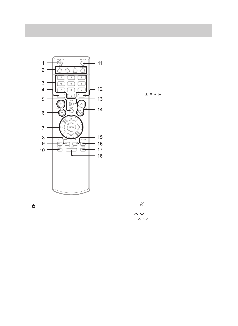
REMOTE CONTROL
1. / I (STANDBY / ON) Button
Press to turn ON the unit or put it in STANDBY (OFF)
mode.
2. TV Button
Press to switch to TV mode.
AV Button
Press to switch to source connected to AV 1 / AV 2
(composite) inputs.
HD Button
Pres s to swit ch to sou rce con nec ted to YUV
(component) inputs and HDMI 1 / HDMI 2 inputs.
DISPLAY Button
Press to change disc status information displayed
on the screen.
3. Number (0 - 9) Buttons
4. •[dot]Button
Press to enter digital sub-channels. (i.e. 11.3 or
12.7)
5. MENU Button
Press to display the on-screen TV menu.
6. VOLUME (- / +) Buttons
Press to adjust the volume level.
7. CURSOR (
, , , ) Buttons
Press to highlight selections on a menu screen and
adjust certain settings.
ENTER Button
Press to conrm selections on a menu screen.
8. CC Button
Press to activate the Closed Captioning feature.
This function only works on programs broadcasted
with captions.
9. EXIT Button
Press to exi t the TV SET UP men u and retur n
directly to normal viewing.
10. SLEEP Button
Press to set the SLEEP timer. The unit will remain
on for the time that is set, and will automatically
shut o afterwards.
11. FUNCTION Button
Press to switch between TV / AV 1 / AV 2 / YUV in /
PC in / HDMI 1 / HDMI 2.
12. LAST CH Button
Press to switch repeatedly between the last two
channels displayed.
13. MUTE
Button
Press to turn o the sound.
14. CH
/ CH Buttons
Press / to change the channels.
15. MTS Buttom
Press to switch between MONO sound, STEREO
sound and Secondary Audio Program (SAP).
16. PICTURE Button
Press to select from preset screen display settings
to ma tch the typ e of show you are watc hing
(Personal / Soft / Movie / Standard / Dynamic).
17. SOUND Button
Press to select from preset sound settings to match
the type of show you are watching (Standard /
Personal / Theater / Voice / Music).
18. FORMAT Button
Press to select the picture format.
Page 8
E-7
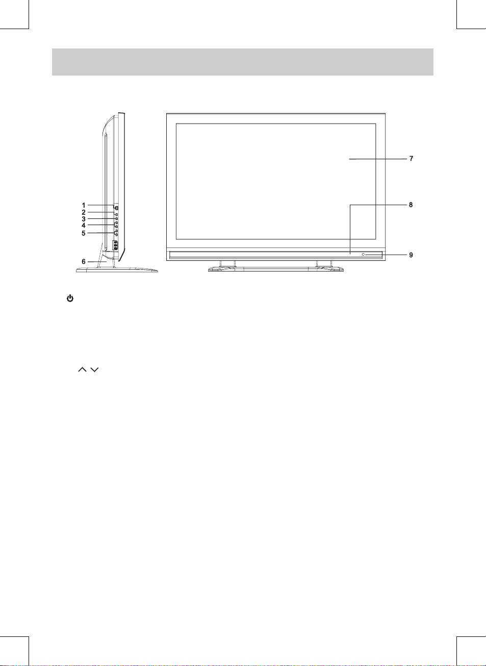
CONTROL REFERENCE GUIDE
FRONT & SIDE VIEWS
1. / I (STD.BY / ON) Button
Turns the unit on and o.
2. MENU Button
Enters the on-screen TV menu.
3. FUNCTION Button
Selects TV / AV 1 / AV 2 / YUV in / PC in / HDMI 1 /
HDMI 2.
4. CH
/ CH Buttons
Confirms selections on the T V menu screen and
changes the TV channels.
5. - VOL + Controls
Adjusts the volume level.
6. Removable Stand
7. Color Screen
8. Speaker
9. Remote Sensor
Receives the remote control signal.
Standby Indicator
Page 9
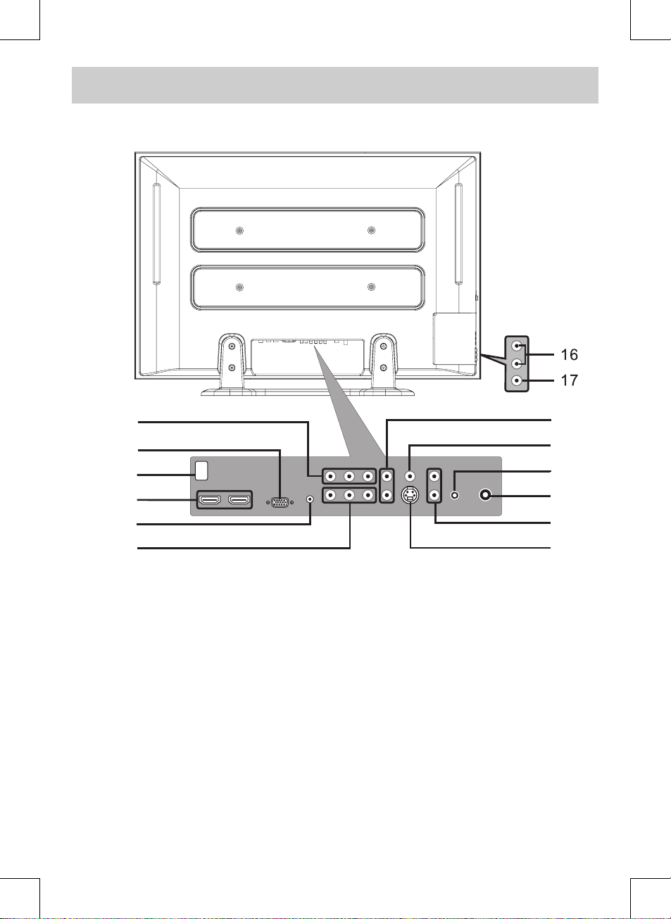
CONTROL REFERENCE GUIDE
E-8
REAR VIEW
10. VIDEO OUT Jack (AV OUT)
AUDIO OUT (Left / Right) Jacks (AV OUT)
11. MONITOR / VGA Jack (PC IN)
12. AC Socket
13. HDMI IN Jacks (HDMI IN 1 / HDMI IN 2)
14. AUDIO Jack (PC IN)
15. COMPONENT VIDEO IN (Y / PB / PR) Jacks
(YUV IN)
16. AUDIO IN (Left/Right) Jacks (AV IN 2)
17. VIDEO IN Jack (AV IN 2)
18. AUDIO IN (Left / Right) Jacks (YUV IN)
19. VIDEO IN Jack (AV IN 1)
20. PHONES Jack
21. TV ANTENNA Terminal
22. AUDIO IN (Left / Right) Jacks (AV IN 1)
23. S-VIDEO Jack (AV IN 1)
10
11
12
13
14
15
18
19
20
21
22
23
Page 10

E-9
CONNECTIONS
CONNECTING A TV ANTENNA / CABLE / SATELLITE
To view television channels correctly, a signal must be received from one of the following sources:
- An indoor or outdoor aerial antenna
- A cable system
- A satellite system
Connecting an Antenna for over-the-air Broadcasts
The tuner in this TV receives ATSC T V signals from an antenna - it thus can receive standard (SDTV) and high
denition (HDTV) over the air broadcasts.
Connecting other Devices to the TV ANTENNA Terminal
The tuner in this TV can also receive analog cable signals or the RF output from a satellite receiver, VCR or cable
box.
CONNECTING AN A/V DEVICE
To connect to other equipment such as a VCR, camcorder, satellite system or cable, etc.
Connecting to a VCR / Camcorder / Satellite System / Cable
Connect the AUDIO and S-VIDEO cable (not included) as shown:
Make sure you connect the cable from the other equipment (AUDIO OUT and S-VIDEO OUT) to this unit AV IN 1
(AUDIO IN and S-VIDEO IN).
NOTE
Plea se refer to the us er manua l
for the other equipment for more
information.
To S-VIDEO
OUT / AUDIO
OUT jacks
To S-VIDEO
IN jack
To AUDIO
IN jacks
(AV IN 1)
Satellite, cable or TV
antenna cable to TV
ANTENNA terminal
(cable not included)
Page 11

CONNECTIONS
E-10
CONNECTING DEVICES WITH A COMPOSITE (YELLOW RCA-TYPE) VIDEO OUTPUT
To connect A/V devices such as a VCR, video game system or camcorder:
Connecting to a VCR / Video Game System / Camcorder
Connect the AUDIO / VIDEO cable (not included) as shown:
Make sure you connect the cable from the other equipment (AUDIO and VIDEO OUT) to this unit AV IN 1 (AUDIO
and VIDEO IN) or AV IN 2 (AUDIO and VIDEO IN).
NOTE
Please refer to the user manual for the other equipment for more information.
CONNECTING DEVICES WITH A COMPOSITE (YELLOW RCA-TYPE) VIDEO INPUT
To connect A/V devices such as a VCR, PVR or camcorder:
Connecting to a VCR / PVR /
Camcorder
Connect the AUDIO / VIDEO cable
(not included) as shown:
Make sure you connect the cable
from the other equipment (AUDIO
and VIDEO IN) to this unit (AUDIO
and VIDEO OUT).
NOTE
Plea se refer to the us er manua l
for the other equipment for more
information.
To AUDIO
/ VIDEO
OUT jacks
To AUDIO /
VIDEO
OUT jacks
To AUDIO / VIDEO
IN jacks
(AV IN 1)
Page 12

E-11
CONNECTIONS
CONNECTING A HIGH-DEFINITION (HD) SOURCE USING COMPONENT CONNECTION
High-Denition (HD) Devices with component video output must be connected to the YUV input.
Connect the component video cable and audio cable (not included) as shown.
Make sure you connect the component video cable and audio cable from the other equipment (COMPONENT
VIDEO OUT and AUDIO OUT) to this unit (COMPONENT VIDEO IN and AUDIO IN - YUV IN).
To COMPONENT
VIDEO OUT jacks
To COMPONENT
VIDEO IN jacks
(YUV IN)
To AUDIO
IN jacks
(YUV IN)
* May require a subscription for receiving
HD channels. Check with your cable/
satellite service provider for details.
CONNECTING A HIGH-DEFINITION (HD) SOURCE USING HDMI CONNECTION
HDMI (High Denition Multimedia Interface) supports both video and audio on a single digital connection for
use with DVD players, DTV, set-top boxes and other digital AV devices. HDMI was developed to provide the
technologies of High Bandwidth Digital Content Protection (HDCP) as well as Digital Visual Interface (DVI) in
one specication. HDCP is used to protect digital content transmitted and received by DVI-compliant or HDMIcompliant displays.
HDMI has the capability to support standard, enhanced or high-denition video plus standard to multi-channel
surround-sound audio. HDMI features include uncompressed digital video, a bandwidth of up to 2.2 gigabytes
per second (with HDTV signals), one connector (instead of several cables and connectors), and communication
between the AV source and AV devices such as DTVs.
HDMI, the HDMI logo and HighDefinition Multimedia Interface are trademarks
or registered trademarks of HDMI licensing LLC.
Conn ect the H DM I cable (no t in clude d) as
shown:
Ma ke sure you connect the cable from the
source equipment (HDMI OUT) to this uni t
(HDMI IN).
Press the HD button to match the video source
output
quality.
To HDMI
OUT jack
To HDMI
IN jack
Page 13

CONNECTIONS
E-12
CONNECTING AN AUDIO AMPLIFIER
This connection allows you to use an audio amplier and external speakers.
Co nne ct the AUDIO c abl e (not
included) as shown:
Make sure you connect the cable
from the other equipment (AUDIO
IN) to this unit (AUDIO OUT).
To AUDIO
OUT jacks
To AUDIO IN jacks
To PC AUDIO OUT jack
To PC connector
CONNECTING A PC
Connect the 15-pin D-SUB PC/VGA
connector from your computer to
the 15- pi n D-SUB PC/ VG A input
on this unit using a monitor cable
and audio cable (not included) as
shown.
Make sure you connect the cable
from the computer (PC Connector
and PC AUDIO) to this unit (PC IN
MONITOR / VGA and AUDIO).
NOTE
When connecting a DVD player to the television, the picture resolution is solely dependent upon the resolution
supported by the DVD player attached. DVD player resolutions vary from 480i to 1080i, and this unit can support
DVD players up to a maximum resolution of 1080i.
Page 14

E-13
CONNECTIONS
CONNECTING THE AC POWER CORD
You can power your TV unit by plugging the detachable AC power cord into the AC socket on the back of the
unit and into a wall AC power outlet. Check that the rated voltage of your unit matches your local voltage. Make
sure that the AC power cord is fully inserted into the unit.
CAUTION: (for North America)
TO P REVE NT ELEC TR IC SHO CK,
MATCH WIDE BLADE OF PLUG TO
WIDE SLOT OF WALL OUTLET, THEN
FULLY INSERT.
NOTES:
• Wh en t h e AC po we r c or d is
p l ug ge d in , t he un it is n o t
completel y dis connected from
the main power, even when the
power is turned o.
• Be su re the A C pow er co rd is
disconnected and all functions are
o before making connections.
• Make sur e all components are
connected correctly.
• When not being used on mains,
the AC Cord should be unplugged
from the unit.
USING HEADPHONES
• Turn d ow n th e volu me befor e
con necting headphones to the
unit, then adjust the volume to
your desired level.
• When headphones are connected,
no sound will come from the front
speakers.
NOTE
Avoid listening to sound at high
le ve ls for pro lo nged peri ods of
time. This may be harmful to you
and may cause hearing loss.
Headphones
(1/8" [3.5mm]
diameter plug)
To AC wall outlet
Page 15

INSTALLATION
E-14
INSTALLING THE BASE STAND
WARNING: The display is very fragile, and must be protected at all times when installing the base stand. Be sure
that no hard or sharp objects, or anything that could scratch or damage the display come in contact with it. Do
NOT place pressure on the rear of the unit at anytime because the screen could crack.
1. Disconnect any cables or cords connected to the unit.
2. Lay the unit down on a flat surface, so the back side is facing up, making sure to place a soft cushioned
material (such as a blanket or thick piece of foam) beneath the screen.
3. Put the stand into the hole at the bottom of the TV.
4. Insert screw into the hole and tighten.
MOUNTING ON THE WALL
This unit is VESA-compliant, and is designed to be wall-mounted with a VESA-compliant 15 3/4” x 7 7/8” (400mm
x 200mm) mounting kit designed for at-panel TVs (sold separately). Mount this unit according to the directions
included with the mounting kit.
NOTE
Remove the base stand before mounting the unit on the wall.
Four mounting holes
(4xM6 screw)
Page 16

TV SETUP
E-15
VIDEO MENU
1. Press the MENU button.
2. Press the ENTER or button to select Video.
3. Use the or button to select the options (Picture Mode, Brightness, Contrast, Saturation, Tint,
Sharpness or Color Temperature). Adjust them using the or button ( The screen will change to your
desired setting); or press the ENTER or button to go into the detailed settings.
4. Press the EXIT button to return to the previous menu.
5. Repeat steps 3 and 4 to adjust other options.
6. To exit the MAIN MENU and return to the normal screen, press the EXIT button repeatedly.
Picture Mode : Select from preset screen display settings to match the type of show you are watching
(Personal, Soft, Movie, Standard & Dynamic). Select Personal mode to recall your customed
settings on brightness, contrast, saturation, tint, sharpness and color temperature.
Brightness : Adjust the brightness of the picture. Brighten or darken the whole picture.
Contrast : Adjust to sharpen the picture quality. The black portions of the picture become richer in
darkness and the white become brighter.
Saturation : Adjust the color saturation of the picture.
Tint : Adjust the tint of the picture (Toward purple / Toward green).
Sharpness : Adjust the sharpness level to improve detail in the picture.
Color Temperature : Adjust the three color temperature of the picture. Choose from Standard (balanced), Warm
(red white), or Cool (blue white) modes.
Auto Adjust : Adjust the screen display automatically.
H. Position : Center the image by moving it left or right.
V. Position : Center the image by moving it up or down.
Phase : Adjust the image if there is icker of screen letters, color misalignment, or blurring.
: Adjust the display clock to change width of the image.
- Resolution : 1024 x 768 max
- Refresh Frequency : 60Hz max
Video
Audio
Setup
Parental
VGA
AutoAdjust
H. Position
V. Position
Phase
Clock
Select EXITENTER
Enter
50
50
Return
3
127
Best resolution
1024x768
TV MODE AV / YUV / HDMI MODE
PC MODE VGA SETTINGS IN PC MODE
Page 17

TV SETUP
E-16
AUDIO MENU
1. Press the MENU button.
2. Use the or button to select Audio, then press the ENTER or button to go into the Audio settings.
3. Use the or button to select the options (Balance, Bass, Treble, Virtual Surround, Reverb or Audio
mode). Adjust them using the or button (The screen will change to your desired setting); or press the
ENTER or button to go into the detailed settings.
4. Press the EXIT button to return to the previous menu.
5. Repeat steps 3 and 4 to adjust other options.
6. To exit the MAIN MENU and return to the normal screen, press the EXIT button repeatedly.
NOTE
Experiment with dierent sound settings until you nd the settings you prefer.
Balance : Adjust the balance level toward the left or right speakers.
Bass : Adjust the bass range.
Treble : Adjust the treble range.
Virtual Surround : Switch on or o the virtual surround eect.
Reverb : Select from preset sound settings (Concert, Living Room, Hall, Arena, Church, Off) to
match the type of show you are watching.
Audio mode : Select from preset audio settings (Standard, Personal, Theater, Voice & Music) to match the
type of show you are watching. Select Personal mode to recall your custom settings on
bass and treble).
TV MODE AV / YUV / HDMI / PC MODE
Page 18

TV SETUP
E-17
TV MENU (For TV Mode Only)
1. Press the MENU button.
2. Use the or button to select TV. Press the ENTER or button to go into the TV settings.
3. Use the or button to select the options (Tuner Mode, Auto Scan, Auto Scan Add CH, Channel Skip, MTS
or Audio Language). Adjust them using the or button (The screen will change to your desired setting); or
press the ENTER or button to go into the detailed settings.
4. Press the EXIT button to return to the previous menu.
5. Repeat steps 3 and 4 to adjust other options.
6. To exit the MAIN MENU and return to the normal screen, press the EXIT button repeatedly.
Tuner Mode : Antenna (over-the-air broadcasts, Ch 2-69) or Cable (cable/satellite broadcasts, CH 1-135)
mode is available.
Auto Scan : Searches for usable stations and stores them in memory.
Auto Scan Add CH : Searches for more usable stations and adds them in memory (The stations stored before
are still kept).
Channel Skip : Skips weak channels and the channels you do not like.
MTS : Select from Stereo / SAP (Secondary Audio Program) / Mono.
Audio Language : Select from English / Spanish / French (Available for digital channels if multiple audio
languages are broadcasted).
NOTE
The SAP (Secondary Audio Program) feature allows a TV station to broadcast other information, which could be
audio in another language.
Channel Skip Setting:
1. Use the or button to select a channel. Press the button to select the last channel of the page, press
again to go to the next page. Press the button to select the rst channel of the page, press again to go to
the previous page.
2. Press the ENTER button to shift between skip or not skip the channel. A check appears in the square. It means
to skip the channel. The channel will not appear when you press the CH /CH Button.
3
4
5
5-1
6
7
8
9
10
2
Video
Audio
TV
Setup
Parental
Analog
Analog
Analog
Analog
Digital KPIX-DT
Analog
Analog
Analog
Analog
Analog
Channel Skip
EXIT
ENTER
Return
Select
Set
Page 19

TV SETUP
E-18
SETUP MENU
1. Press the MENU button.
2. Use the or button to select Setup. Press the ENTER or button to go into the Setup settings.
3. Use the or button to select the options (OSD Language, Time Setup, Caption, Gamma, Power Saving,
ISM Mode or Restore setting). Adjust them using the or button (The screen will change to your desired
setting); or press the ENTER or button to go into the detailed settings.
4. Press the EXIT button to return to the previous menu.
5. Repeat steps 3 and 4 to adjust other options.
6. To exit the MAIN MENU and return to the normal screen, press the EXIT button repeatedly.
OSD Language :
Select from English / Español / Français.
Time Setup Setting
Time Zone : Select the time zone from Eastern Time / Indiana / Central Time / Mountain Time / Arizona
/ Pacic Time / Alaska / Hawaii.
Sleep Timer : Select the time to turn the unit to Standby mode automatically: O -> 5 Minutes -> 10
Minutes -> 15 Minutes -> 30 Minutes -> 60 Minutes -> 90 Minutes -> 120 Minutes -> O.
TV MODE AV / YUV MODE
Video
Audio
TV
Setup
Parental
AutoSynchronization
Date
Time
Timer
Power OnTimer
Power OffTimer
Time
EXIT Return
Select
On
Off
00:00:00
00:00:00
2007/01/01
07:42:49
HDMI /PC MODE
Page 20

TV SETUP
E-19
When you set the ‘Time’, the option will be shown:
Auto Synchronization: Select On to synchronize time with the digital TV channel signal. Select O to keep the
time unsynchronized.
Date : Press the or button to locate the position, and press the number buttons to input
date.
Time : Press the or button to locate the position, and press the number buttons to input
time.
Timer : Select On to activate automatically power on/o.
Power On Timer : Press the or button to locate the position, and press the number buttons to input
power on time.
Power O Timer : Press the or button to locate the position, and press the number buttons to input
power o time.
Caption Setting
Analog Closed Caption : Select the analog closed caption.
Digital Closed Caption : Select the digital closed caption or turn it o.
Digital Caption Style : Select as Broadcaster to use the default digital caption style of the broadcaster. Select
Custom to activate the caption style items and set your preferred detailed settings.
NOTE
This function only works on ATSC programs broadcasted with captions.
Gamma Setting
High gamma values display whitish images and low gamma values display high contrast images. Use the or
button to select the options (Middle, Bright or Dark).
Power Saving Setting
This function allows you to reduce the power consumption of the TV. Use the or button to select the desired
power saving level (Level 0~4).
ISM(Image Sticking Minimization) Mode Setting
A frozen or still picture from a PC/video game displayed on the screen for prolonged periods will result in a ghost
image remaining even when you change the image. This option avoids allowing a xed image to remain on the
screen for prolonged periods. There are 4 options (Standard, White Screen, Screen Saver or Inversion) for your
choice.
Restore Setting
If you reset the TV to the factory settings, all your present settings on Video & Audio will be erased and replaced
by the factory’s default settings. However, picture settings in PC mode and Parental settings will not be erased.
Video
Audio
TV
Setup
Parental
Analog Closed Caption
Digital Closed Caption
Digital Caption Style
Caption
EXIT Return
Select
CC1
Off
Video
Audio
TV
Setup
Parental
Caption Style
Font Size
Font Color
Font Opacity
BackgroundColor
BackgroundOpacity
Window Color
Window Opacity
Digital Caption Style
EXIT Return
Select
As Broadcaster
Small
Green
Solid
Black
Translucent
White
Transparent
Page 21

TV SETUP
E-20
PARENTAL MENU
Password
1. Press the MENU button.
2. Use the or button to select Parental. Press the ENTER or button to conrm. The menu locked screen
will be displayed.
3. Enter a 4-digit password. Once entered, the screen will enter the Parental menu. The preset password is 0000.
You can edit the parental control level or change the password. See Parental Control Settings described as
below.
Parental Control Setting
1. Use the or button to select various Parental settings. Press the ENTER or button to go into the detailed
settings.
2. Use the , , and buttons to move among the rating levels. Press the ENTER button to change the mode
between Blocked and Allowed.
3. Press the EXIT button to return to the previous menu.
4. Repeat steps 1 - 3 to adjust other options.
5. To exit the MAIN MENU and return to the normal screen, press the EXIT button repeatedly.
Rating Enable : Select On to edit the following parental items. Select O to disable parental control.
Open V-Chip : Reads the ratings from ATSC TV programs if there is rating information broadcasted, and
denies the channel when its rating is higher than the ratings you pre-set.
TV MODE AV / YUV / HDMI / PC MODE
If you forget the password,
enter "8888" to unlock parental control.
Page 22
TV SETUP
E-21
U.S.
TV
Ratings
U.S.
Movie
Ratings
Canadian
E n g l i s h
Ratings
Canadian
F r e n c h
Ratings
TV-Y : Recommended for all children.
TV-Y7 : Recommended for all children age 7 and above.
TV-G : General Audience.
TV-PG : Parental Guidance Suggested.
TV-14 : Parental Strongly Cautioned.
TV-MA : Mature Audience Only.
G : GENERAL AUDIENCES, Suitable for all ages.
PG : PARENTAL GUIDANCE SUGGESTED - Some material may not be suitable
for children.
PG-13 : PARENTS STRONGLY CAUTIONED - Some material may be inappropriate
for children under 13.
R : RESTRICTED, Under 17 requires accompanying parent or adult guardian
for viewing in movie theaters.
NC-17 : No one 17 or under admitted in movie theaters,
X : Adults Only.
C : Children.
C8+ : Recommended for children age 8 and older.
G : GENERAL AUDIENCES, Suitable for all ages.
PG : PARENTAL GUIDANCE SUGGESTED - Some material may not be suitable
for children.
14+ : Viewers 14 years and older.
18+ : Adult Programming.
G : GENERAL AUDIENCES, Suitable for all ages.
8 ans+ : Not recommended for young children.
13 ans+ : Not suitable for children under the age of 13.
16 ans+ : Not suitable for children under the age of 16.
18 ans+ : Adult Programming.
Page 23

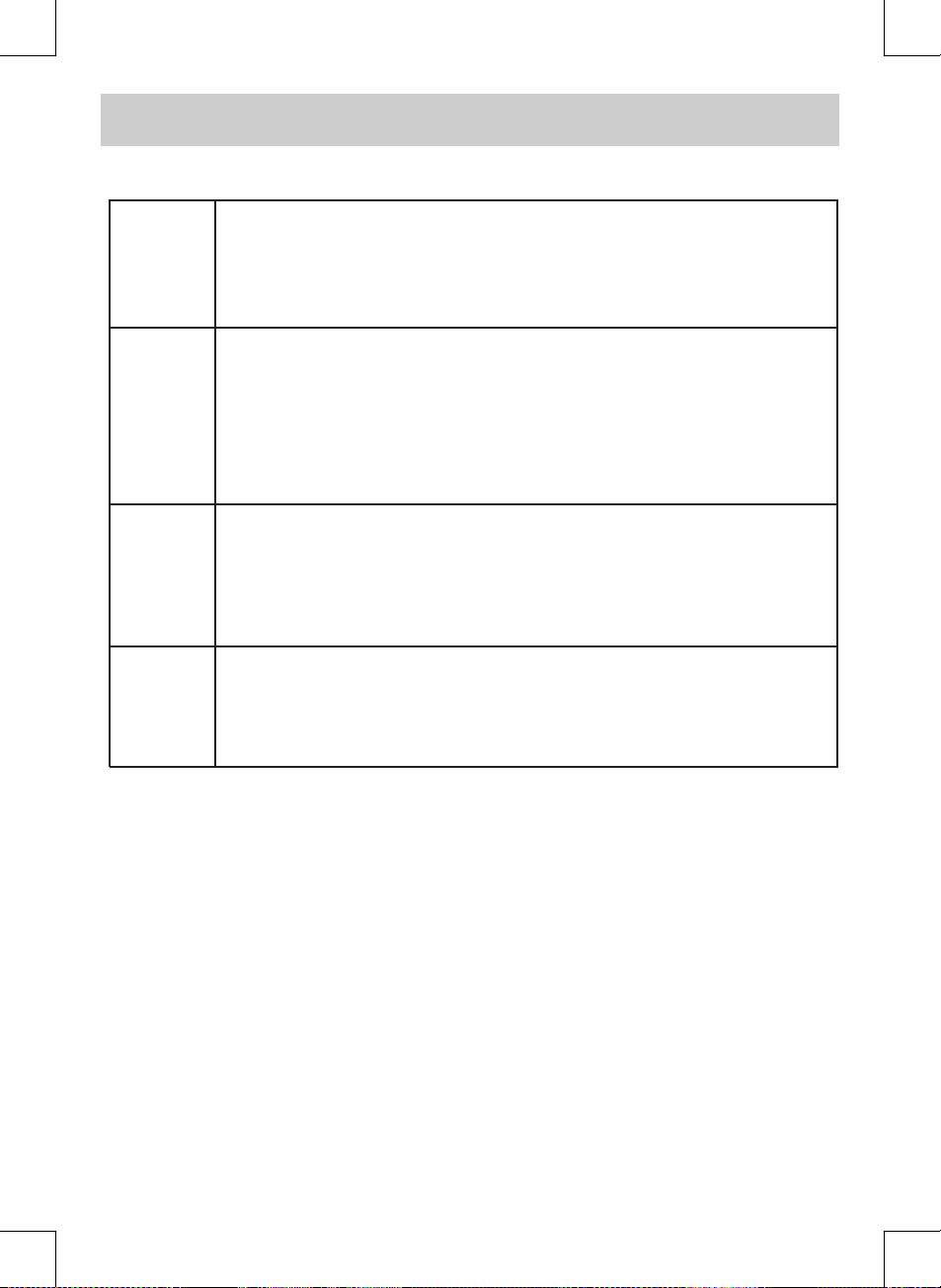
TROUBLESHOOTING GUIDE
E-22
SYMPTOM
CAUSE (AND REMEDY)
No power.
The remote does not function.
TV
Bad Picture (snow, multiple
images, distortion, blurry)
Black and white picture.
No picture or sound.
Colored patches of picture.
No sound is output from the
HDMI out.
• Make sure the AC power cord is connected.
• The unit is not turned on.
• Remove any obstacles between the remote and the unit.
• Use the remote near the unit.
• Point the remote at the remote sensor on the unit.
• Replace the batteries in the remote with new ones.
• Check the location of the antenna and adjust it if necessary.
• Make sure the antenna cable is rmly connected.
• Make sure all input cables are rmly connected.
• Check the VIDEO MENU within the TV SETUP MENU.
• Check to make sure the program you are watching is broadcast in
color and not black & white.
• Make sure the unit is plugged in and turned on.
• Make sure that TV mode is selected.
• Try a new channel to check for possible station trouble.
• Make sure the antenna is connected properly.
• Increase the volume.
• Make sure the antenna or audio video source device is working
properly.
• Make sure all cables are rmly connected.
• Check for local interference.
• Make sure there are no unshielded electrical devices nearby that are
causing interference.
• Turn the unit o for 30 minutes, then try it again.
• Check the connection between this unit and the HDMI out jack of
other equipment.
• Check your TV system setup correctly.
Page 24

E-23
LIMITED WARRANTY
Notes
.................................................................................................................................................................................................................................
.................................................................................................................................................................................................................................
.................................................................................................................................................................................................................................
.................................................................................................................................................................................................................................
.................................................................................................................................................................................................................................
.................................................................................................................................................................................................................................
.................................................................................................................................................................................................................................
.................................................................................................................................................................................................................................
.................................................................................................................................................................................................................................
.................................................................................................................................................................................................................................
.................................................................................................................................................................................................................................
.................................................................................................................................................................................................................................
Important: Also keep your “Bill of Sale” as proof of purchase.
Model no. ...................................................... Product name ..................................................
Type of set .............................................................................................................................................
Serial no. ........................................................ Invoice no. ........................................................
Date purchased ............................................. Dealer name .....................................................
FOR SERVICE AND REPAIR, PLEASE VISIT
www. venturer.com
© 2008 VENTURER Electronics Inc.
Page 25

E-24
LIMITED WARRANTY
VENTURER ELECTRONICS (“VENTURER”) makes the following limited warranty. This limited warranty extend to the original
consumer purchaser and is limited to non-commercial use of the product.
Ninety (90) Day Parts & Labor Warranty
VENTURER products purchased in the United States are warranted to be free from defects in materials or workmanship for
a period of ninety (90) days from the date of their original retail purchase. If the unit fails to conform to this warranty, we will
service the product using new or refurbished parts and products, at VENTURER’s sole discretion.
During a period of ninety (90) days from the eective warranty date, VENTURER will provide, when needed, service labor to
repair a manufacturing defect at its designated Service Center. To obtain warranty service in the Untied States, you must
rst call our Customer Support Center at (800) 252-6123, during the hours listed in the box below. The determination
of service will be made by VENTURER Customer Support. PLEASE DO NOT RETURN YOUR UNIT TO ALCO WITHOUT
PRIOR AUTHORIZATION. New or remanufactured replacements for defective parts or products will be used for repairs by
VENTURER at its designated Service Center for ninety (90) days from the eective warranty date. Such replacement parts
or products are warranted for an additional ninety (90) days from the date of repair or replacement. The Customer will be
required to ship the unit to the Service Center indicated at the time Customer Support is contacted to make the necessary
repairs. The customer is responsible for all transportation charges to the service facility.
Packaging and Shipping Instruction
When you send the product to the Alco service facility you must use the original carton box and packing material or an
equivalent as designated by VENTURER.
LIMITED WARRANTY
Your Responsibility
(1) You must retain the original sale receipt to provide proof of purchase.
(2) These warranties are eective only if the product is purchased and operated in the U.S.A. or Canada.
(3) Warranties extend only to defects in material or workmanship, and do not extend to any product or parts which have
been lost or discarded, or damage to product or parts caused by misuse, accident, improper operation or maintenance,
or use in violation of instructions provided with the product, or to product which has been altered or modied without
authorization of VENTURER, or to products or parts thereof which have had the serial number removed or changed.
Out of Warranty
In the event your product requires repair after the limited warranty period has expired, please contact our Customer
Support Center at 1-800-252-6123 or
www.venturer.com.
Hours: Monday–Thursday: 9–7, Friday: 9–5, Saturday: 9–12 EST.
Important:
You are responsible for any transportation, shipping or insurance relative to the return of product to our Product
Returns Center.
All warranties implied by state law, including the implied warranties of merchantability and tness for a particular purpose,
are expressly limited to the duration of the limited warranties set forth above. With the exception of any warranties implied
by state law as hereby limited, the foregoing warranty is exclusive and in lieu of all other warranties, guarantees, agreements
and similar obligations of manufacturer or seller with respect to the repair or replacement of any parts. In no event shall
VENTURER be liable for consequential or incidental damages.
No person, agent, distributor, dealer or company is authorized to change, modify or extend the terms of these warranties in
any manner whatsoever. The time within action must be commenced to enforce any obligation of VENTURER arising under
the warranty or under any statute, or law of the United States or any state thereof, is hereby limited to ninety (90) days from
the date of purchase. This limitation does not apply to implied warranties arising under state law.
This warranty gives you specic legal rights and you may also have other rights, which may vary, from state to state. Some
states do not allow limitation on how long an implied warranty lasts, when an action may be brought, or the exclusion or
limitation of incidental or consequential damages, so the above provisions may not apply to you.
For more information on other products and services, please visit our web site at
www.venturer.com
Page 26

E-25
Digital Television Transition Notice:
This device contains a digital television tuner, so it should receive digital over the air TV programming, with a
suitable antenna, after the end of full-power analog TV broadcasting in the United States on February 17, 2009.
Some older television receivers, if they rely on a TV antenna, will need a TV Converter to receive over the air
digital programming, but should continue to work as before for other purposes (e.g., for watching low-power TV
stations still broadcasting in analog, watching pre-recorded movies, or playing video games).
For more information, please see www.DTV.gov or call our number below. For information on the TV Converter
program, and on government coupons that may be used toward the purchase of
one, see www.dtv2009.gov, or call the NTIA at 1-888-DTV-2009.
Digital Television Transition Notice
Page 27

E-26
UNIT INCH
41 1/83 1/4
29 1/8
12 1/5
10 1/2
18 3/8
12 3/4
28 1/2
Printed in China
811-284291W021
 Loading...