

Page 1
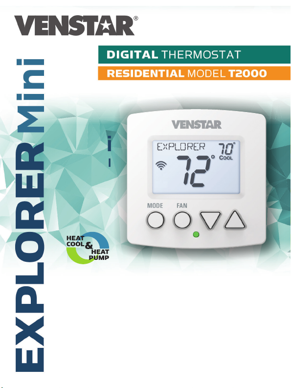
7 Day Programmable • Up to 2-heat & 2-cool
with
Wi-Fi
and local
API
Owner’s Manual
& Installation
Instructions
Page 2

CAUTION
Follow the Installation Instructions before proceeding. Set the
thermostat mode to “OFF” prior to changing settings in setup
or restoring Factory Defaults.
FCC Compliance Statement
This equipment has been tested and found to comply with the limits for an
intentional radiator, pursuant to Part 15, subpart C of the FCC rules. These limits
are designed to provide reasonable protection against harmful interference
in a residential installation. This equipment generates, uses and can radiate
radio frequency energy and, if not installed and used in accordance with
the instructions, may cause harmful interference in radio communications.
However, there is no guarantee that the interference will not occur in a particular
installation. If this equipment does cause harmful interference to radio or
television reception, which can be determined by turning the equipment off and
on, the user is encouraged to try to correct the interference by one or more of the
following measures:
• Reorient or relocate the receiving antenna.
• Increase the separation between the equipment and receiver.
• Connect the equipment into an outlet on a circuit different from that of the
receiver.
• Consult the dealer or an experienced radio or TV technician for help.
Notice: Only peripherals complying with FCC limits may be attached to this
equipment. Operation with noncompliant peripherals or peripherals not
recommended by Venstar, is likely to result in interference to radio and TV
reception. Changes or modifications to the product, not expressly approved by
Venstar could void the user’s authority to operate the equipment.
FCC - INDOOR Mobile Radio Information:
To comply with FCC/IC RF exposure limits for general population / uncontrolled
exposure, the antenna(s) used for this transmitter must be installed to provide a
separation distance of at least 20 cm from all persons and must not be co-located
or operating in conjunction with any other antenna or transmitter.
This Device complies with Industry Canada License-exempt RSS standard(s).
Operation is subject to the following two conditions: 1) this device may not
cause interference, and 2) this device must accept any interference, including
interference that may cause undesired operation of the device.
i
Page 3

Under Industry Canada regulations, this radio transmitter may only operate using
an antenna of a type and maximum (or lesser) gain approved for the transmitter
by Industry Canada. To reduce potential radio interference to other users, the
antenna type and its gain should be so chosen that the equivalent isotropically
radiated power (e.i.r.p.) is not more than that necessary for successful
communication.
Cet appareil est conforme avec Industrie Canada, exempts de licence standard
RSS(s). Son fonctionnement est soumis aux deux conditions suivantes: 1) ce
dispositif ne doit pas causer d’interférences, et 2) ce dispositif doit accepter
toute interférence, y compris les interférences qui peuvent causer un mauvais
fonctionnement de l’appareil.
En vertu des règlements d’Industrie Canada, cet émetteur de radio ne peut
fonctionner en utilisant une antenne d’un type et maximale (ou moins) Gain
approuvé pour l’émetteur par Industrie Canada. Pour réduire les interférences
radio potentielles aux autres utilisateurs, le type d’antenne et son gain doivent
être choisis afin que la puissance isotrope rayonnée équivalente (PIRE) ne est pas
plus de ce qui est nécessaire pour une communication réussie.
We, Venstar, declare under our sole responsibility that the device to which
this declaration relates: Complies with Part 15 of the FCC Rules. Operation is
subject to the following two conditions: (1) this device may not cause harmful
interference, and (2) this device must accept any interference received, including
interference that may cause undesired operation.
This Explorer Mini thermostat has the ability to receive updates to its firmware.
Periodically firmware updates are released by the manufacturer to add features
and/or performance enhancements. This manual was produced reflecting the
most current firmware/feature set at the time of publication, firmware rev. 1.0.
Firmware releases after rev. 1.0 may not be adequately depicted in this manual.
Please refer to the appropriate website or contact your place of purchase to learn
about changes to the thermostat after firmware release 1.0.
MUH-SKYPORT8
ii
Page 4

Table of Contents
CAUTION
Installation Instructions ..........................................................1
Wire Connections .....................................................................2
Thermostat Backplate .............................................................3
Dip Switch Settings .................................................................4
Connect to WiFi.......................................................................10
Front Panel ...............................................................................13
Display ......................................................................................14
Basic Operation ......................................................................16
User Setup................................................................................17
Backlight Operation ..........................................................18
Service Filter ......................................................................19
Installer Setup .........................................................................21
Programming a Daily Schedule ...........................................27
About Advanced Features & Operation ..............................29
Advanced Setup Table ...........................................................34
IMPORTANT
Follow Installation Instructions carefully. Disconnect
Power to the Heater/Air Conditioner before removing
the old thermostat and installing the new thermostat.
© Copyright 2017, All Rights Reserved T2000
iii
Page 5

Glossary of Terms
Auto-Changeover: A mode in which the thermostat will turn on the
heating or cooling based on room temperature demand.
Cool Setpoint: The warmest temperature that the space should rise
to before cooling is turned on (without regard to deadband).
Deadband: The number of degrees the thermostat will wait, once a
setpoint has been reached, before energizing heating or cooling.
Differential: The forced temperature difference between the heat
setpoint and the cool setpoint.
Heat Setpoint: The coolest temperature that the space should drop
to before heating is turned on (without regard to deadband).
Icon: The word or symbol that appears on the thermostat display.
Mode: The current operating condition of the thermostat (i.e. Off,
Heat, Cool, Auto, Program On).
Non-Programmable Thermostat: A thermostat that does not have the
capability of running Time Period Programming.
Programmable Thermostat: A thermostat that has the capability of
running Time Period Programming.
Temperature Swing: Same as Deadband.
Time Period Programming: A program that allows the thermostat
to automatically adjust the heat setpoint and/or the cool setpoint
based on the time of the day.
iv
Page 6
Installation Instructions
Remove and Replace the old thermostat
To install the thermostat properly, please follow these step by step
instructions. If you are unsure about any of these steps, call a qualified
technician for assistance.
• Installationtools:Smallatbladescrewdriver,Phillipsscrewdriver,
wire cutters and wire strippers.
• MakesureyourHeater/AirConditionerisworkingproperlybefore
beginninginstallationofthethermostat.
• Carefullyunpackthethermostat.Savethescrews,anybrackets,
and instructions.
• TurnoffthepowertotheHeating/AirConditioningsystematthemain
fusepanel.Mostresidentialsystemshaveaseparatebreakeror
switchfordisconnectingpowertothefurnace.
• Removethecoveroftheoldthermostat.Ifitdoesnotcomeoffeasily,
checkforscrews.
• Loosenthescrewsholdingthethermostatbaseorsubbasetothewall
and lift away.
• Ifyouhaveasmartphonehandy,takeaphotoofthewiringforfuture
reference.
• Disconnectthewiresfromtheoldthermostat.Tapetheendsofthe
wiresasyoudisconnectthem,andmarkthemwiththeletterofthe
terminal for easy reconnection to the new thermostat.
• Keeptheoldthermostatforreferencepurposes,untilyournew
thermostatisfunctioningproperly.
1
Page 7
Installation Instructions
Wire Connections
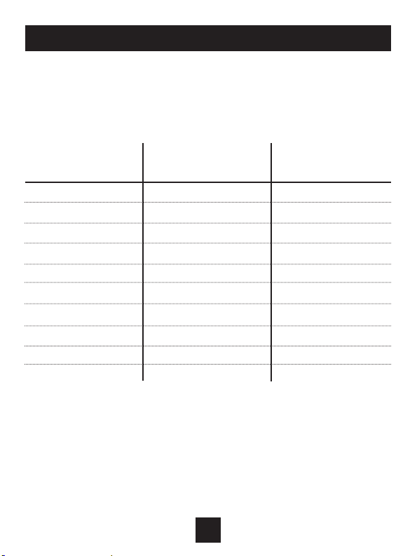
Iftheterminaldesignationsonyouroldthermostatdonotmatchthose
on the new thermostat, refer to the chart below or the wiring diagrams
that follow.
Wire from the Install on the
old thermostat Function new thermostat
terminal marked connector marked
G or F Fan G
Y1, Y Cooling Y1
W1, W Heating W1/O/B
Rh, R, M, Vr, A Power R
C Common C
O/B Rev. Valve W1/O/B*
W2 2nd Stage Heat W2
Ck1 Dry Contact Switch CK
CKGND Dry Contact Switch R
* O/B is used if your system is a Heat Pump.
2
Page 8
Installation Instructions
The Explorer Mini Thermostat Backplate
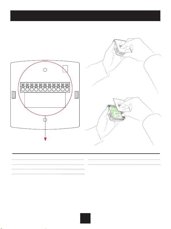
To remove the thermostat backplate:
Gently separate the display from the
basebypullingfromthecenter.
RGY1W2W1/O/BY2C
R 24 VAC return
G Fan relay
W1/O/B 1st stage heat circuit
W2 2nd stage heat circuit
Y1 1st stage compressor relay
CK1
Y2 2nd stage compressor relay
C 24 VAC common
CK1 Dry Contact
IMPORTANT: This thermostat requires both R (24 VAC Return) and C (24 VAC
Common) wires be connected to the backplate terminals to operate properly.
3
Page 9
Installation Instructions
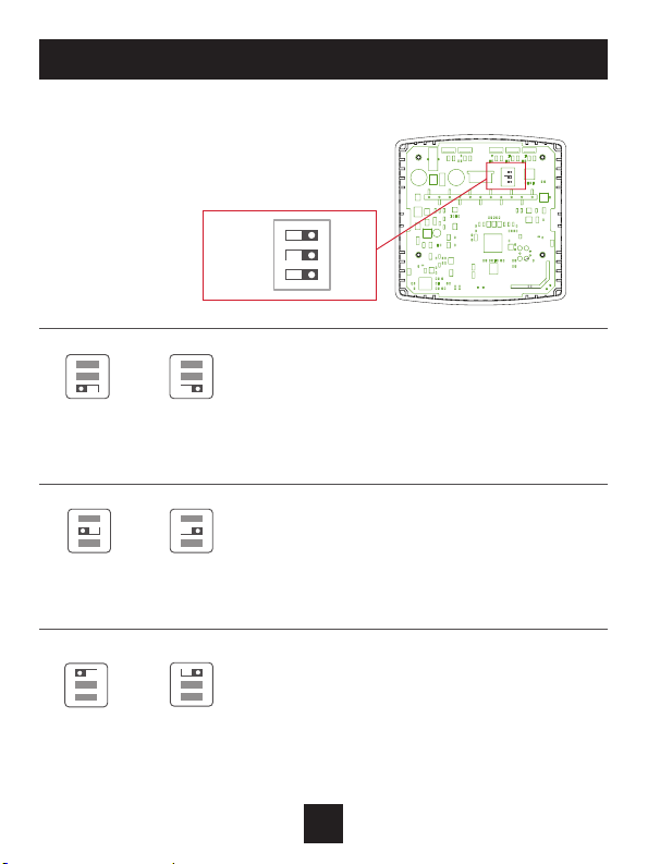
Check Dip Switch
Ensure which switch is correct for your
system.Dipswitchesarelocatedonthe
backofthethermostat.
GAS/EL
HP
B
O
23
ON
GAS
ELEC
1
ON
1 2 3
ON
GAS ELECORGAS ELEC
O B BO
ON
1 2 3
OR
ON
GAS/EL HPORGAS/EL HP
ON
1 2 3
ON
GAS/EL
O
GAS
HP
B
23
ON
1
ELEC
Thisswitch(GASorELEC)controlshowthe
thermostatwillcontroltheFan(G)terminalin
1 2 3
heatingmode.WhenGAS is chosen, the thermostat
willnotenergizetheFan(G)terminalinheating.
WhenELECischosenthethermostatwillenergize
thefaninheating.
For Heat Pump Only
WhentheGAS/EL or HPdipswitchisconguredfor
1 2 3
HP,thisdipswitch(OorB)mustbesettocontrol
theappropriatereversingvalve.IfO is chosen, the
W1/O/Bterminalwillenergizeincooling.IfB is
chosen, the W1/O/Bterminalwillenergizeinheating.
Thisdipswitchconguresthethermostattocontrol
aconventionalgas/electricsystemoraheatpump.
1 2 3
Ifyoursystemisanythingotherthanaheatpump,
leavethisswitchsetforGAS/EL.
4
Page 10
Installation Instructions
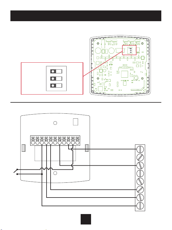
1 Stage Heat, 1 stage Cool
Dip Switch Settings
GAS/EL
HP
B
O
23
ON
GAS
ELEC
1
GAS/EL
O
GAS
HP
B
23
1
ELEC
ON
Thermostat
RGY1W2W1/O/BY2C CK1
HVAC
Equipment
C
W2
W1
O or B
Y2
Y1
G
R
5
Page 11
Installation Instructions
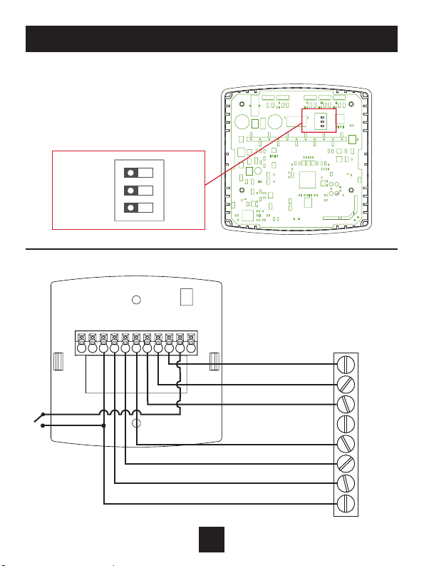
2 Stage Heat, 2 Stage Cool
Dip Switch Settings
GAS/EL
HP
B
O
23
ON
GAS
ELEC
1
GAS/EL
O
GAS
HP
B
23
1
ELEC
ON
Thermostat
RGY1W2W1/O/BY2C CK1
HVAC
Equipment
C
Y2
W1
O or B
W2
Y1
G
R
6
Page 12
Installation Instructions
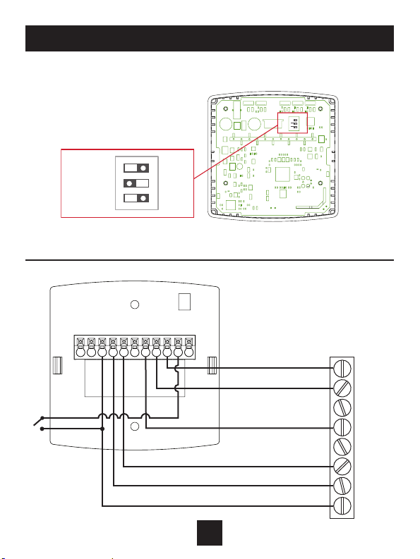
Single Stage Heat Pump with AUX Heat
Dip Switch Settings
GAS/EL
HP
B
O
23
ON
GAS
ELEC
1
GAS/EL
*
O
GAS
ON
HP
B
23
1
ELEC
*Reversingvalvechoice,OorB,isdependantonthetypeofvalveinstalled
in the heat pump.
Thermostat
RGY1W2W1/O/BY2C CK1
HVAC
Equipment
C
Y2
W1
O or B
Y2
Y1
G
R
7
Page 13
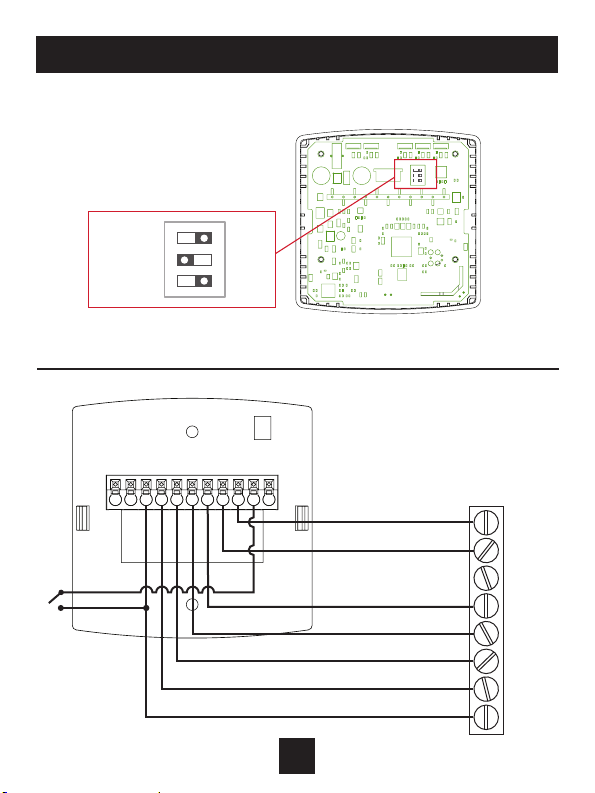
Installation Instructions
Dual Stage Heat Pump with AUX Heat
Dip Switch Settings
GAS/EL
HP
B
O
23
ON
GAS
ELEC
1
GAS/EL
*
GAS
O
ON
HP
B
23
1
ELEC
*Reversingvalvechoice,OorB,isdependantonthetypeofvalveinstalled
in the heat pump.
Thermostat
RGY1W2W1/O/BY2C CK1
HVAC
Equipment
C
Y2
W1
O or B
W2
Y1
G
R
8
Page 14
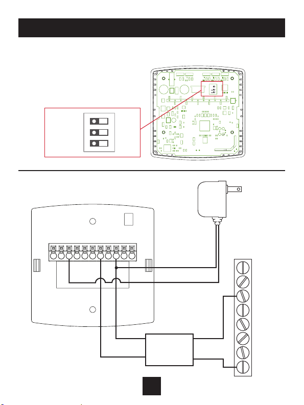
Installation Instructions
Heat Only - with Venstar 2-Wire Kit - ACC0436
GAS/EL
HP
B
O
23
ON
GAS
ELEC
Dip Switch Settings
1
GAS/EL
O
GAS
Thermostat
RGY1W2W1/O/BY2C CK1
HP
B
23
1
ELEC
ON
BROWN WHITE
ORANGE
9
BLACK
BLACK
24 VAC
Isolation
Relay
RED
Input
120VAC
HVAC
Equipment
C
W2
W1
O or B
Y2
Y1
G
R
Page 15
Connect to Wi-Fi Overview
Atminimummtherst3tasksbelowmustbecompletedtoaccessyour
thermostatremotelyfromabrowser.The4thstepisoptional(highly
recommended)andonlyisneededtoaccessyourthermostat(s)froma
mobiedevice.
These steps are:
1. SuccessfulconnectiontoalocalWi-FiAccessPointwithinternet
access.
2. ConrmreceiptofaSkyportgeneratedvericationemail(thisonly
occursonceduringtheSkyportaccountsetup).
3. A6-digitcodeobtainedfromthethermostatissuccessfullyentered
intoaSkyportaccount.
4. SuccessfullydownloadandinstalltheVenstarSkyportapponyour
mobiledevice(s).
Your thermostat operates on the 2.4 Ghz, Wi-Fi b/g/n band.
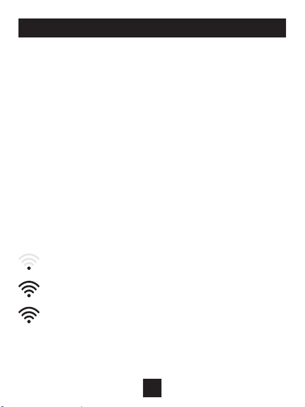
Wi-Fi Symbol Legend
Whentheonlythe‘dot’oftheWi-Fisymbolappears=not
connected to an access point.
WhenthefullWi-Fisymbolappears=connectedtoan
access point.
WhenthefullWi-Fisymbolappearsandthe‘dot’ofthesymbolis
ashing=connectedtoSkyport.
10
Page 16
Connect to Wi-Fi Overview
Wi-Fi Setup
The Venstar Configurator App is needed to configure the Wi-Fi
Settings of this thermostat
• Download the Venstar Configurator App
fromyourmobiledevice’sAppStore.
• Open the Venstar Configurator App
- ChoosetheExplorerMinithermostatbyslidingthe
thermostatpicturesatthetopoftheapps’display
totheleftuntilyouseeapictureoftheExplorerMini.
- PressandholdtheFANbuttonofthethermostatfor
approximately5secondstoenterWi-Fisetupscreens.
- PressthecoolerbuttontosetupWi-Fi.
- FollowtheinstructionsthatappearontheVenstar
ConguratorApp.
Connect to Skyport
AlthoughthereismorethanonewaytocreateaSkyportaccount,the
steps below illustrate account creation from a browser. To create a
Skyportaccountathermostatmustbejoinedtotheaccount.
IfthethermostatisconnectedtothelocalWi-FiAccessPoint,butyou
donothaveaSkyportaccount,youmaycreateanaccountandjointhe
thermostattotheaccountbydoingthefollowing:
1.Openyourbrowserto:http://venstar.skyportcloud.com
2. Select“Createaccountnow”
Create Account Now
ICON
3. Follow on screen instructions to create an account and add a
thermostattotheSkyportaccount.
11
Page 17

Connect to Wi-Fi Overview
Join a Thermostat to Skyport
IfthethermostatisconnectedtothelocalWi-Fiaccesspointbutnotyet
joinedtoanexistingSkyportaccount,youmayjointhethermostattothe
accountbydoingthefollowing:
1. LogintoyourSkyportaccount.
2. Selectthe“Location”youwanttoaddathermostatinto.
3. Selectthe“Thermostattab”.
4. Select“+Addthermostat”.Ascreenwill‘pop-up’askingfora
sixdigitcode.
5. PresstheFANbuttononthethermostatfor5seconds.
6. PresstheWarmerbuttononthethermostat.
7. Asixdigitcodewillappearonthethermostat’sdisplay.
8. EnterthesixdigitcodeintoyourSkyportaccount.
Wi-Fi Status Screens
Pressandholdthefanbuttononthethermostatfor5seconds.When
“Wi-FiSetup”appearsonthedisplay,presstheMODEbutton.Pressing
theupordownbuttonwillsequencethroughthefollowinginformation:
• APName
• APSignalStrength
• IPAddress
• SkyportStatus
• APIStatus
12
Page 18
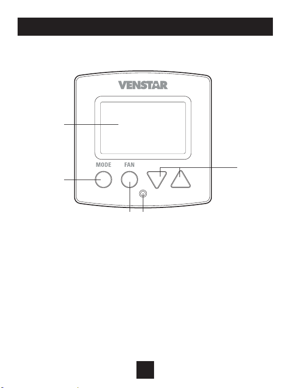
Front Panel
1
3
1 Backlit Display
2 Up/Warmer, Down/Cooler Buttons
3 Mode Button
4 Fan Button
5 Heat or Cool Indicator
2
4 5
Heat = Red, Cool = Green
13
Page 19
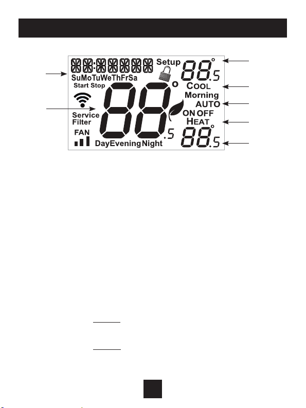
Display
2
3
1 ModeIndicators
Selectstheoperationalmodeoftheequipment.
HEAT-Indicatestheheatingmode.
COOL-Indicatesthecoolingmode.
AUTO-Indicatesthesystemwillautomaticallychangeover
between heat and cool modes as the temperature
varies.
OFF -Indicatesheatingandcoolingareturnedoff.
2 ClockwithDayoftheWeek
Indicatesthecurrenttimeandday.Thisclockisalsousedto
programthetimeperiodschedules.
3 RoomTemperatureDisplay
Indicates current room temperature.
4 DesiredSetTemperature
Indicates desiredroomtemperature(s).
4
1
1
1
4
14
Page 20
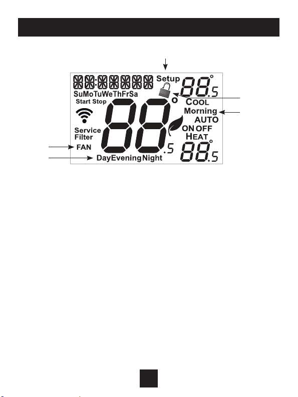
Display
6
7
5
5 Morning, Day, Evening & Night icons
Indicatesthedaypartofthetimeperiodprogram.
6 Setup icon
Indicates the thermostat is in the setup mode.
7 Fan icon
WhenonlytheFaniconisdisplayed,thefanisalways
on.IftheFANisnotonthedisplay,thentheFANisin
Automodeandwillrunonlywhennecessarytoheat
or cool.
8 Locked icon
Indicatesthethermostat’scontrolbuttonshave
beenlocked.
8
5
15
Page 21
Basic Operation
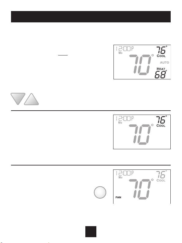
Selecting Your Desired Temperature (adjusting the setpoints)
Auto-Changeover Mode
PressingtheWARMERorCOOLERbuttonsin
Automodewilladjustboth the heat and cool
setpointssimultaneously.Toadjusttheheat
andcoolsetpointsindividually,chooseHEAT
modetoadjusttheheatsetpoint,andCOOL
modetoadjustthecoolsetpoint,thenreturn
toAUTOmode.
Adjustthedesiredset
temperature with these
buttons
Heat or Cool Mode
PressingtheUPorDOWNbuttonsin
HeatorCoolmodewilladjustonlythe
heat or cool set temperature.
Using the Fan Button
Fan indicates constant fan
operation. You may turn the fan
onevenifthethermostatisinthe
Offmode.PressingtheFANbutton
togglesthisfeatureonoroff.
FAN
16
Page 22
User Setup
Table for button
presses that are
required for
enteringvarious
menus
TO ENTER MENUS BUTTON PRESS
SetupSteps ....................... MODE&FANfor5seconds
TimeSchedule ..................MODE&Upfor2seconds
EmergencyHeat ............... Up&FANfor2seconds
LockoutButtons ................ MODE,Up&Downfor2seconds
Calibration .......................... MODE&Downfor2seconds
WirelessSetup ................. FANfor5Seconds
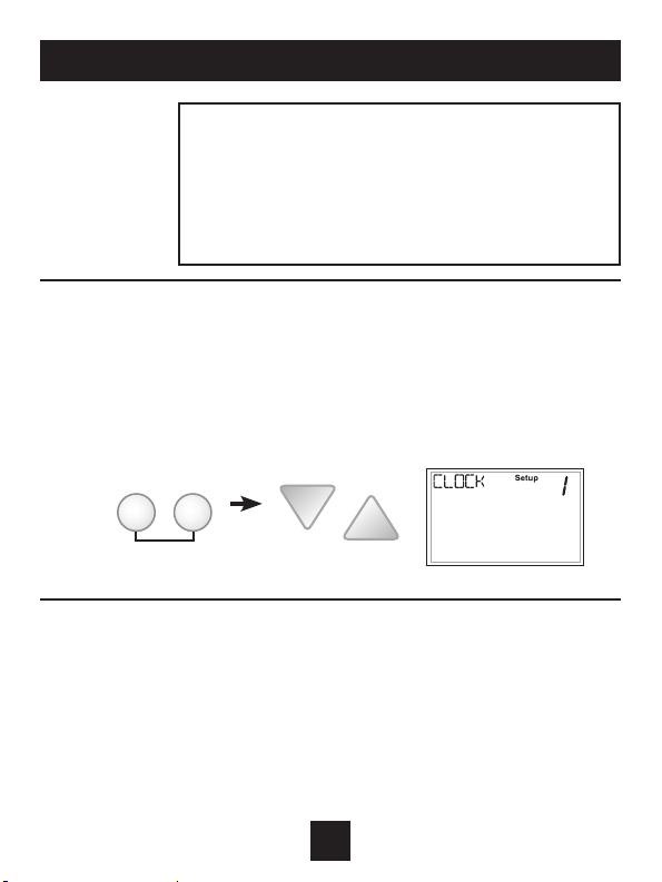
How to Change Settings in the Setup Screens
To enter the setup screens, press the MODE button, and
simultaneously press FAN button for 5 seconds. Release the buttons
when you see “Setup” on the display. Use the WARMER or COOLER
buttons to adjust the value of your selection. Press MODE to advance
to the next setup step. Press MODE and FAN together again to leave
the setup screens.
FANMODE
press together for
5 seconds
Setting the Clock and Day (setup step 1 & 2)
WhenyourthermostatisconnectedtoSkyportCloudServices,thetimeandday
oftheweekarecontrolledbySkyport.Thereisnolocaladjustment,Skyportalso
adjuststhetimeforDaylightSavingsTimeaswell.
TosetthetimeanddaywhennotconnectedtoSkyport;enterthesetupscreens
bypressingtheModebuttonandsimultaneouslypressingtheFanbuttonfor
5seconds.
(Continued)
17
Page 23
User Setup: Backlight Operation
(Continued)
Setupstep1adjuststheclock.UsetheWarmer/UporCooler/Downbuttonsto
adjustthetime.
PresstheModebuttontoadvancetostep2.
SelectthedayoftheweekusingtheWarmer/UporCooler/Downbuttons.
LeavethesetupscreensbyagainpressingtheModebuttonandsimultaneously
pressingtheFanbuttonfor5seconds.
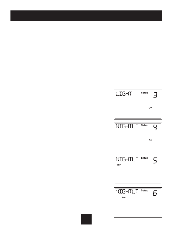
Backlight (Setup Steps 3-6)
Backlight (setup step 3)
Off - Backlight turns on only with a button
press and turns off after 8 seconds.
On - Backlight is on continuously.
Night Dimmer (setup step 4) - Selecting On
allows for turning off the backlight of the
display during specific times of the day,
usually at night.
Night Dimmer Start Time (setup step 5) 12:00 am to 12:00 am
Night Dimmer Stop Time (setup step 6) 12:00 am to 12:00 am
18
Page 24
User Setup: Service Filter
These setup steps allow the user to monitor FAN runtimes and program
service alerts. Service alerts appear on the display. If the thermostat is joined
to a Skyport account, then the user may be alerted by Skyport Cloud Services
when to change the filter.
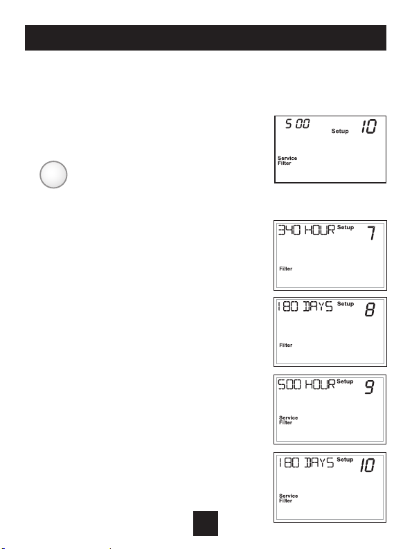
Runtime hours
or days appear in
FAN
Press and hold FAN
to clear reset runtime.
Service Filter Runtime (Setup Steps 7-10)
Current Service Filter Runtime Hours (Setup Step 7)
- This counter keeps track of the number of hours of
fan runtime in the Heating mode, Cooling mode, and
in stand alone Fan operation.
Press FAN to reset.
Current Service Filter Calendar Days (Setup Step 8)
- This counter displays the total number of calendar
days that have elapsed since the counter was reset
to help the user track Fan runtime.
Press FAN to reset.
Set Service Filter Runtime Hours (Setup Step 9) -
This timer allows the user to specify the number
of hours the fan will run before the “Replace Filter”
alert will be displayed. Press COOLER continuously
until OFF is displayed to disable this alert.
Set Service Filter Calendar Days (Setup Step 10) -
This timer allows the user to specify the number of
calendar days that will elapse before the “Replace
Filter” alert will be displayed. Press COOLER
continuously until OFF is displayed to disable
this feature.
the clock display.
19
Page 25
User Setup: Setpoint Limits
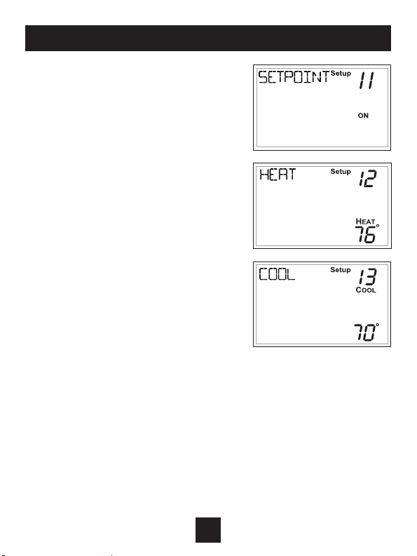
Setpoint Limits (Setup Steps 11-13)
When this feature is set to ON, the Heat
and Cool Setpoints may be restricted to
preset levels in Setup Steps 12 and 13.
Maximum Heat Setpoint
(Setup Step 12)
Minimum Cool Setpoint
(Setup Step 13)
20
Page 26
Installer Setup
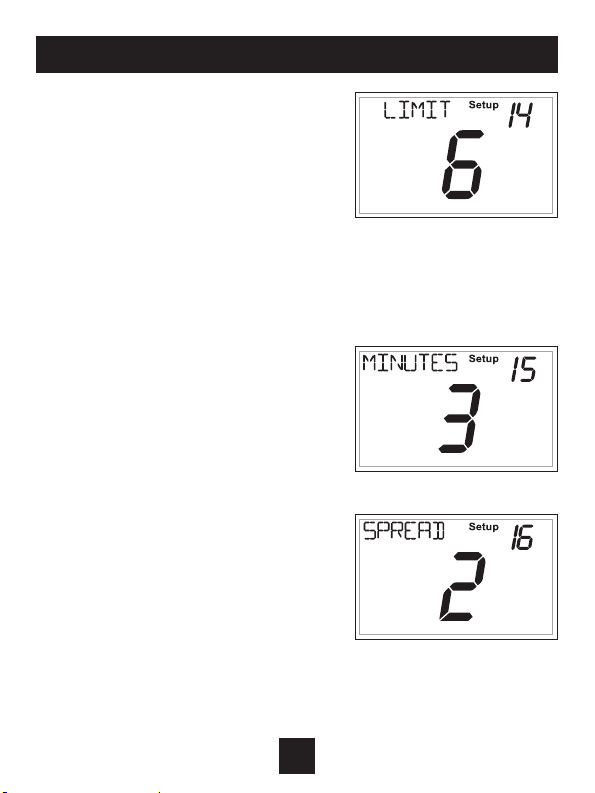
Cycles Per Hour (Setup Step 14)
TheCyclesPerHoursettingmaylimitthe
numberoftimesperhouryourHVACunit
mayenergize.Forexample,atasetting
of6cyclesperhourtheHVACunitwill
onlybeallowedtoenergizeonceevery
10minutes.TheCyclesPerHourlimit
maybeoverriddenandresetbypressing
theWARMERorCOOLERbuttonsonthe
thermostat.SettingsareNoLimit,2,3,4,5,
or 6 cycles per hour.
Compressor Minimum
Off Minutes (Setup Step 15)
This feature allows the user to set a
minimum off time for the compressor.
Settingsare0to5mins.
Minimum Heat/Cool Setpoint
Difference (Setup Step 16)
This feature allows the user to set the
minimumgapbetweenHeatandCool
setpointsinAUTOmode.Selectfrom
0to6degrees.
21
Page 27
Installer Setup
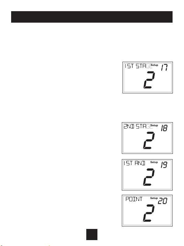
Deadband Settings (setup steps 17 - 20)
The Deadband is the number of degrees or
minutes that the thermostat waits before it
initiates the stages of heating or cooling.
1st Stage Deadband (Setup Step 17)
Speciesthetemperaturedifferencebetween
the room temperature and the desired setpoint
beforetherststageofheatingorcooling
isallowedtoturnon.(1-6degrees)For
example,iftheheatsetpointis68˚andthe1st
Stagedeadbandissetto2degrees,theroom
temperature will need to reach 66˚ before the
heat turns on.
2nd Stage Deadband (Setup Step 18)
Speciestheadditionaltemperaturedifference
aftertherststageturnsonbeforethesecond
stageisactivated.(0˚-10˚)
Minutes Between 1st and 2nd Stage
(Setup Step 19)
Speciestheminimumtime(inminutes)afterthe
rststageturnsonbeforethesecondstagecan
turnon.(0˚-60˚)
Second Stage Turnoff Point (Setup Step 20)
Specieswhethersecondstagewillturnoffat
rststagedeadbandorremainonuntiltheroom
temperaturedemandissatised.Choose
betweenDeadbandorSetpoint.
22
Page 28
Installer Setup
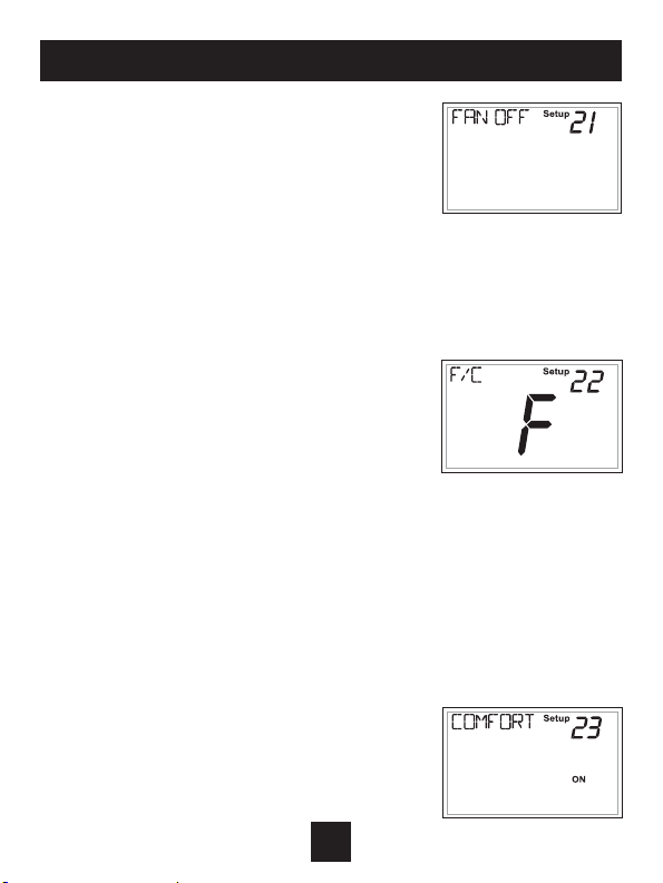
Fan Off Delay in Seconds (setup step 21)
This feature allows the user to increase the
coolingorelectricstripheatingefciencyofthe
system.Thethermostatmaybeprogrammedto
continuerunningthefanafteracallforcooling
orelectricstripheatinghasbeensatised.This
delay can be set for 0, 30, 60, 90, or 120 seconds.
If set to 0, the fan will not run after a call for
coolingorelectricstripheatinghas
been satisfied.
Fahrenheit or Celsius (setup step 22)
This feature allows the thermostat to display
temperatureinFahrenheitorCelsius.
Comfort Recovery (setup step 23)
WithComfortRecoveryon,thethermostatwillattempttoreachthe
Morningsetpointtemperatureattheexacttimeprogrammedinto
thethermostat.ComfortRecovery,onlyworkswhenthethermostat
enterstheMorningperiodfromtheNightPeriod.Forexample,ifthe
NightPeriodissetfor11pmat65°Fheatingand85°Fcooling,andthe
MorningPeriodissetfor6amat72°Fheatingand75°Fcooling,the
thermostatwillturnthesystemonbefore6aminanefforttobringthe
temperaturetoitscorrectsettingatexactly6am.Thethermostatlearns
fromexperience,howearlytoturnon,sopleaseallow4-8daysaftera
programchangeorafterinitialinstallationtogive
ComfortRecoverytimetoadjust.Ifusedwitha
heat pump, electric strip heat will be disabled
whileComfortRecoveryisactive.
23
Page 29
‘Idle’ ‘Active’
Dry
Contact
‘Idle’ ‘Active’
Dry
Contact
‘Idle’ ‘Active’
Installer Setup
Dry Contact Operation
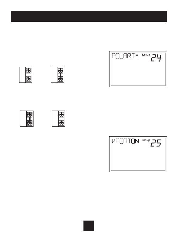
Dry Contact Polarity (setup step 24)
Open (Normally Open)-Thedry
contact is open until the connected
deviceclosesthecircuit.
Dry
Contact
Closed (Normally Closed)-The
dry contact is closed until the
connecteddeviceopensthecircuit.
Dry
Contact
Dry Contact Use (Setup Step 25 )
Condensate Pan - If selected when the
DryContactisactive,thethermostat
willlockoutcompressorterminal(s)and
“CONDENSATEPAN”willappearonthe
display.
Vacation-IfVacationisselectedwhenthedrycontactisactive,
thethermostatwillbeforcedintoAWAY/Unoccupiedsettings.
FDD - IfFDDisselectedwhenthedrycontactisactive,“EQUIP
FAULT”willappearonthedisplay.
Dry
Contact
Dry
Contact
24
Page 30
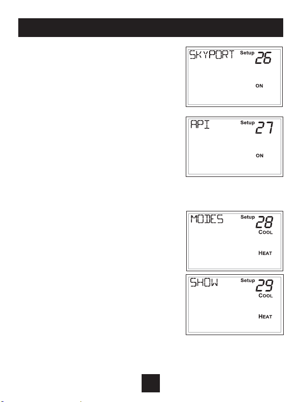
Installer Setup
Skyport Cloud Services
(setup step 26)
IfsettoON,thethermostatmay
communicateandreceivedatafrom
theSkyportCloudServices.
Local API (setup step 27)
TurningonthelocalAPIallows3rd
party software to interface with the
thermostat such as a home
automation system.
NOTE: It is permissable to enable
both Skyport and the local API at the
same time.
Available Modes (setup step 28)
This setup step may restrict the use
ofthisthermostatto:Heatonlyor,
Coolonly,orHeatandCool,orAuto
changeoveroperation.
Show Clock (setup step 29)
Thissetupstepwillallowforremovalof
theclockanddayoftheweekfromthe
display.OFFremovesthetimeandday
from the display.
25
Page 31
Installar Setup
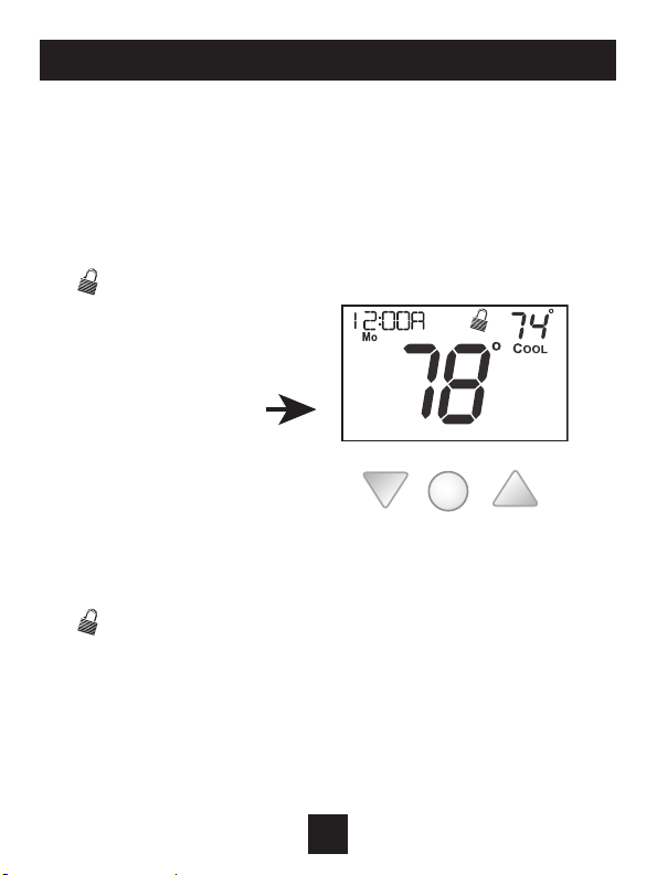
Locking/Unlocking the Keypad
Topreventunauthorizeduseofthethermostat,thefrontpanel
buttonsmaybedisabled.Todisable,or‘lock’thekeypad,press
andholdtheMODEbutton.WhileholdingtheMODEbutton,
presstheWARMERandCOOLERbuttonstogether,fortwo
seconds.
The icon will appear on the display, then release the buttons.
Press all three
buttons in the order
outlined above for
keypad lockout
To unlockthekeypad,pressandholdtheMODEbutton.While
holdingtheMODEbutton,presstheWARMERandCOOLER
buttonstogether,fortwoseconds.
The icon will disappear from the display, then release the
buttons.
MODE
26
Page 32

Programming a Daily Schedule
Programming a Daily Schedule
To enter Time Period Programming screens,
Press and hold MODE and UP until
the scrolling prompt appears.
Select Day of Week to program -
PresstheWARMERorCOOLERbuttonstochoosethedayofthe
week.PressMODEtoadvancetothenextstep.
This thermostat features four programmable time periods per
24 hour day: Morning, Day, Evening, and Night. The start time
for each time period is adjustable. The stop time for each time
period is the start time for the next period. Each time period, or
day part may be individually disabled.
Select the Day to Program - PresstheWARMERorCOOLER
buttonstoselectthedesiredDayoftheWeek.
Enable/Disable Morning Period - PresstheWARMERorCOOLER
buttonstoselectONorOFF.IfthedefaultONisselected,then
theMorningperiodwillruncompletewiththeModeandSet
Pointsselected.IfOFFisselectedthentheMorningdaypartwill
beskippedandthethermostatwillusethenextdaypartthatis
enabled.
MODE
27
Page 33

Programming a Daily Schedule
Select Morning Mode - PresstheWARMERorCOOLERbuttons
toselectthedesiredmode,whichincludesOFF.PressMODEto
advancetothenextstep.
Select Morning Start Time - PresstheWARMERorCOOLER
buttonstoadjustthetimeofdaydesired.PressMODEto
advancetothenextstep.
Select Morning Cool Setpoint - PresstheWARMERorCOOLER
buttonstoadjustthecoolsetpointdesired.Thisstepwillappear
ifCoolorAutoModewasselectedinthestepwheretheMorning
modeisspecied.PressMODEtoadvancetothenextstep.
Select Morning Heat Setpoint - PresstheWARMERorCOOLER
buttonstoadjusttheheatsetpointdesired.Thisstepwillappear
ifHeatorAutoModewasselectedinthestepwherethe
Morningmodeisspecied.PressMODEtoadvancetothe
nextstep.
Repeat Enable, Mode, Start Time and Setpoint programming for
Day, Evening, and Night.
“Copy Current Day to Next Day” isavailable-PresstheUP
buttontoCopythecurrentday’sprogramtothenextday.Press
Modeagaintocontinuecopyingthefollowingday.
Press and hold the MODE/WARMER Buttons to exit Time Period
Programming at any time.
28
Page 34

About Advanced Features & Operation
Deadband Operation
Controls up to two Heat and two Cool stages.
The 1st Stageofheatorcoolisturnedonwhen:
(A)Thetemperaturespreadfromthesetpointisequaltoorgreater
than:the setpoint plus the 1st stage deadband.This1ststagedeadbandisadjustablefrom1-6degreesandthedefaultistwodegrees.
The 2nd Stageofheatorcoolisturnedonwhen:
(A)The1stStagehasbeenonforaminimumoftwominutes
(defaultsetting).
AND
(B)Thetemperaturespreadfromthesetpointisequaltoorgreater
than:the setpoint plus the 1st stage deadband, plus the 2nd stage
deadband.This2ndstagedeadbandisadjustablefrom0-10
degrees.
29
Page 35
About Advanced Features & Operation
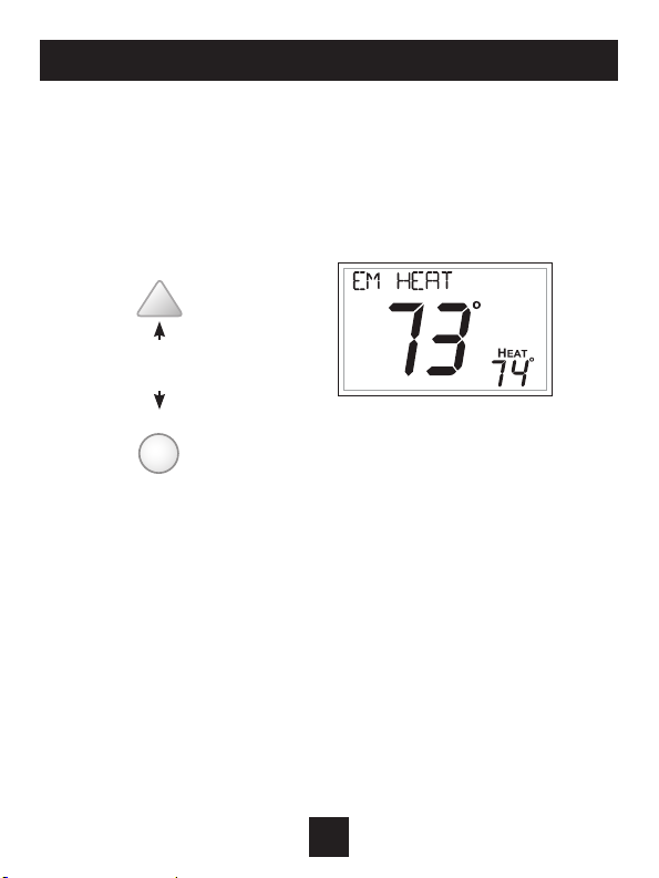
Emergency Heat
OnlyavailableifyouhaveaHeatPumpinstalled.Toinitiatethe
Emergency Heat feature, press the FANbutton.WhileholdingtheFAN
button press the UP button for two seconds.
Thedisplaywillread‘EMHEAT’
(EmergencyHeat).
Press for
Emergency Heat
FAN
DuringEmergencyHeatoperationthethermostatwillturnonthefan
andtheAuxstripheatwhenthereisademandforheat.Alsoduring
EmergencyHeat,heatpumpoperationwillbeunavailable.
Exit Emergency Heat
FollowthesamestepsasenteringEmergency HeatbypressingtheFAN
and UPbuttons,fortwoseconds.DuringEmergencyHeat,onlyOFFand
HEATmodesareavailablebypressingtheMODE button.
30
Page 36
About Advanced Features & Operation
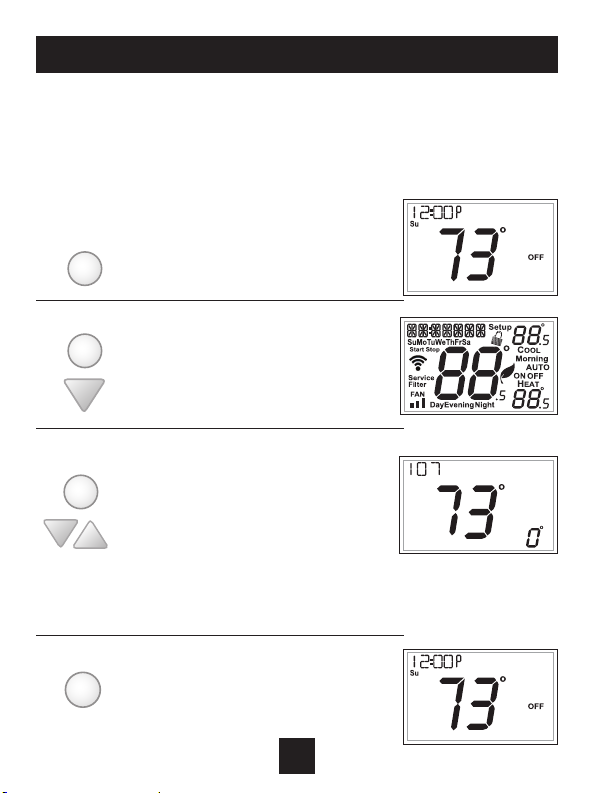
Calibration
Undernormalcircumstancesitwillnotbenecessarytoadjust
the calibration of the temperature sensor. If calibration is
required,pleasecontactatrainedHVACtechniciantocorrectly
performthefollowingprocedure.
MODE
1 Place the thermostat in the OFF mode.
2 Press and hold the MODE button. While
MODE
holding the MODE button, press and hold
the DOWN button for 5 seconds.
All icons will appear on the display.
3 Press the MODE button once. The thermostat
MODE
temperature will be displayed and may be
calibrated using the UP or DOWN buttons. The
calibrated oset from the “raw” temperature
reading is displayed in the lower right corner.
Additionally, on this screen you may view the
Software Version in the upper left corner.
4 After calibration is complete, press the
MODE
MODE button once to save your changes
and return to normal operation.
31
Page 37
About Advanced Features & Operation
Factory Defaults
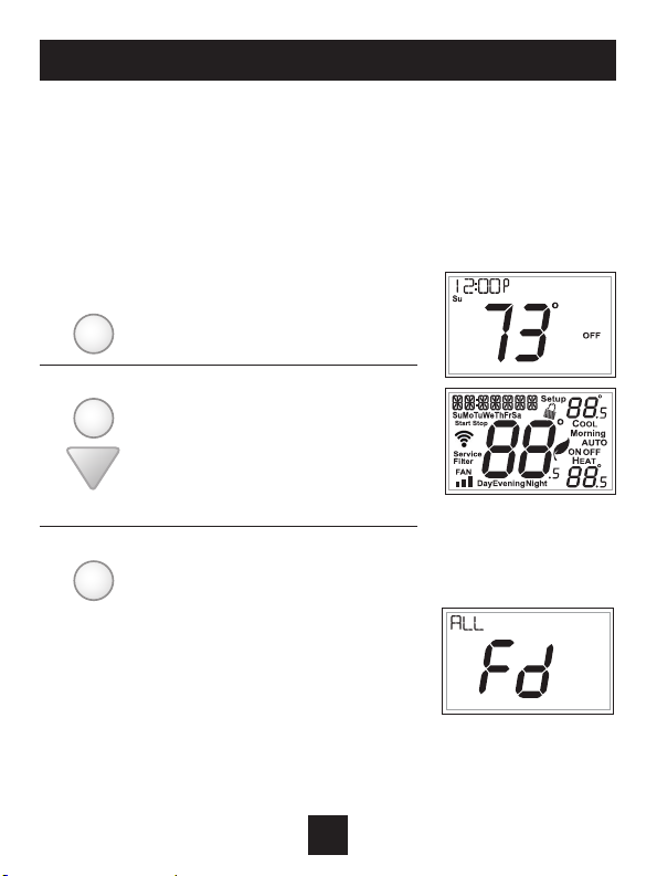
If,foranyreason,youdesiretoreturnallthestoredsettingsback
tothefactorydefaultsettings,followtheinstructionsbelow.
WARNING: This will reset all Time Period and Advanced
Programming to the default settings. Any information entered
prior to this reset will be permanently lost.
MODE
1 Placethethermostatinthe
OFF mode.
2 PressandholdtheMODE
MODE
button.Whileholdingthe
MODEbutton,pressand
holdtheDOWNbuttonfor
5seconds.Alliconswill
appear on the display.
3 A.Afteralloftheiconsappear,
FAN
releasetheMODEandDOWN
buttons.
B.PressandholdtheFAN
button for 2 seconds.
Fd (Factorydefaultsettings)
andALLwillappearonthe
display.
(Continued)
32
Page 38
About Advanced Features & Operation
(Continued)
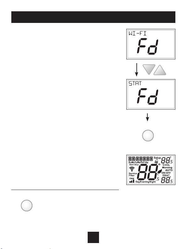
Younowhavetheoptionof
restoringthefactorysettings
tojustWi-Fi(Wi-Fi),orjustthe
thermostat (STAT),orboththe
thermostatandWi-Fi(ALL).
C.Selectoneoftheabove
optionsusingtheUporDown
buttons.
D.PressFanfor2secondsto
restorethefactorysettings.
Afterfactorysettingsare
restored, the thermostat
display will return to the
“allicon”screen.
MODE
4 Toreturntonormaloperation;
PresstheMODE button twice.
FAN
33
Page 39
Advanced Setup Table
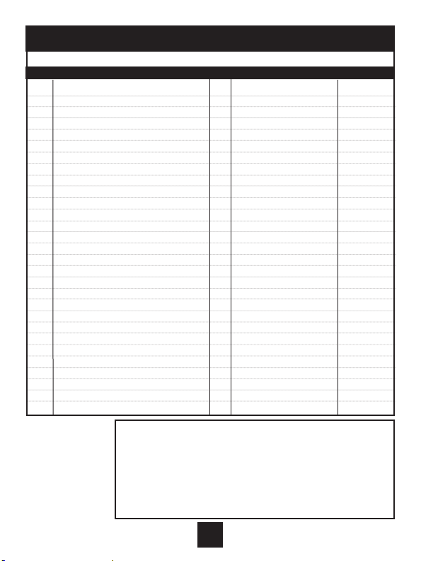
Step# Description Pg# Range FD
1 Set Clock 17 12A - 12A
2 Set Day of Week 17 Monday - Sunday
3 Backlight 18 On, Off, 6pm-6am Off
4 Night Dimmer 18 On/Off Off
5 Night Dimmer Start Time 18 12A - 12A 8:00PM
6 Night Dimmer Stop Time 18 12A - 12A 6:0 0AM
7 Current Service Filter Runtime Hours 19 0-1999 Hours 0
8 Current Service Filter Calendar Days 19 0-720 Hours 0
9 Set Service Filter Runtime Hours 19 0-1999 Hours 0
10 Set Service Filter Calendar Days 19 0-720 Days 0
11 Setpoint Limits 20 On, Off Off
12 Maximum Heat Setpoint Limit 20 35 - 99 Degrees 74
13 Minimum Cool Setpoint Limit 20 35 - 99 Degrees 70
14 Cycles Per Hour 21 No Limit, 2, 3, 4, 5, 6 6
15 Compressor Minimum Off Minutes 21 0, 3, 5 Minutes 5
16 Min. Heat/Cool Setpoint Difference 21 0 - 6 Degrees 2
17 1st Stage Deadband 22 1 - 6 Degrees 2
18 2nd Stage Deadband 22 0 - 10 Degrees 2
19 Minutes Between 1st and 2nd Stage 22 0 - 60 Minutes 2
20 2nd StageTurnoff Point 22 Deadband, Setpoint Deadband
21 Fan Off Delay 23 0, 120 Seconds 0
22 F/C 23 Fahrenheit(F),Celsius(C) F
23 Comfort Recovery 23 On, Off Off
24 Dry Contact Polarity 24 Open, Closed Open
25 Dry Contact Use 24 CondensatePan,Vacation,FDD Vacation
26 Skyport 25 On, Off On
27 Local API 25 On, Off Off
28 Available Modes 25 Heat,Cool,HeatorCool,Auto Auto
29 Show Clock 25 On, Off On
FD = Factory Default Setting
Table for button
presses that are
required for
enteringvarious
menus
TO ENTER MENUS BUTTON PRESS
SetupSteps .......................... MODE&FANfor5seconds
TimeSchedule .....................MODE&Upfor2seconds
EmergencyHeat .................. Up&FANfor2seconds
LockoutButtons ................... MODE,Up&Downfor2seconds
Calibration ............................. MODE&Downfor2seconds
WirelessSetup .................... FANfor5Seconds
34
Page 40

Warranty
One-Year Warranty - This Product is warranted to be free from defects in material and
workmanship. If it appears within one year from the date of original installation, whether or
not actual use begins on that date, that the product does not meet this warranty, a new or
remanufactured part, at the manufacturer’s sole option to replace any defective part, will
be provided without charge for the part itself provided the defective part is returned to the
distributor through a qualified servicing dealer.
THIS WARRANTY DOES NOT INCLUDE LABOR OR OTHER COSTS incurred for diagnosing,
repairing, removing, installing, shipping, servicing or handling of either defective parts or
replacement parts. Such costs may be covered by a separate warranty provided by the installer.
THIS WARRANTY APPLIES ONLY TO PRODUCTS IN THEIR ORIGINAL INSTALLATION LOCATION AND
BECOMES VOID UPON REINSTALLATION.
LIMITATIONS OF WARRANTIES – ALL IMPLIED WARRANTIES (INCLUDING IMPLIED WARRANTIES
OF FITNESS FOR A PARTICULAR PURPOSE AND MERCHANTABILITY ) ARE HEREBY LIMITED IN
DURATION TO THE PERIOD FOR WHICH THE LIMITED WARRANTY IS GIVEN. SOME STATES DO
NOT ALLOW LIMITATIONS ON HOW LONG AN IMPLIED WARRANTY LASTS, SO THE ABOVE MAY
NOT APPLY TO YOU. THE EXPRESSED WARRANTIES MADE IN THIS WARRANTY ARE EXCLUSIVE
AND MAY NOT BE ALTERED, ENLARGED, OR CHANGED BY ANY DISTRIBUTOR, DEALER, OR OTHER
PERSON WHATSOEVER.
ALL WORK UNDER THE TERMS OF THIS WARRANTY SHALL BE PERFORMED DURING NORMAL
WORKING HOURS. ALL REPLACEMENT PARTS, WHETHER NEW OR REMANUFACTURED, ASSUME
AS THEIR WARRANTY PERIOD ONLY THE REMAINING TIME PERIOD OF THIS WARRANTY. THE
MANUFACTURER WILL NOT BE RESPONSIBLE FOR:
1. Normal maintenance as outlined in the installation and servicing instructions or owner’s
manual, including filter cleaning and/or replacement and lubrication.
2. Damage or repairs required as a consequence of faulty installation, misapplication, abuse,
improper servicing, unauthorized alteration or improper operation.
3. Failure to start due to voltage conditions, blown fuses, open circuit breakers or other damages
due to the inadequacy or interruption of electrical service.
4. Damage as a result of floods, winds, fires, lightning, accidents, corrosive environments or other
conditions beyond the control of the Manufacturer.
5. Parts not supplied or designated by the Manufacturer, or damages resulting from their use. 6.
Manufacturer products installed outside the continental U.S.A., Alaska, Hawaii, and Canada.
7. Electricity or fuel costs or increases in electricity or fuel costs for any reason whatsoever
including additional or unusual use of supplemental electric heat.
8. ANY SPECIAL INDIRECT OR CONSEQUENTIAL PROPERTY OR COMMERCIAL DAMAGE OF ANY
NATURE WHATSOEVER. Some states do not allow the exclusion of incidental or consequential
damages, so the above may not apply to you.
This warranty gives you specific legal rights and you may also have other rights which may vary
from state to state.
Page 41

Printed on recycled paper.
P/N 88-1192 12/17
 Loading...