

Page 1

USER MANUAL
2
HAA85BL
SELF-CONTAINED DIGITAL ACCESS CONTROL KEYPAD WITH BACKLIGHT
ONAFHANKELIJK DIGITAAL TOETSENBORD MET ACHTERGRONDVERLICHTING
DIGICODE NUMÉRIQUE AUTONOME AVEC RÉTRO-ÉCLAIRAGE
EIGENSTÄNDIGES DIGITALES CODESCHLOSS MIT HINTERGRUNDBELEUCHTUNG
TECLADO DIGITAL AUTÓNOMO CON RETROILUMINACIÓN
GEBRUIKERSHANDLEIDING 19
MODE D’EMPLOI 35
MANUAL DEL USUARIO 51
BEDIENUNGSANLEITUNG 67
Page 2
HAA85BL
2
USER MANUAL
1. Introduction & Features
To all residents of the European Union
Important environmental information about this product
This symbol on the device or the package indicates that disposal of the device after its lifecycle could harm
the environment.
Do not dispose of the unit (or batteries) as unsorted municipal waste; it should be taken to a specialized
company for recycling.
This device should be returned to your distributor or to a local recycling service.
Respect the local environmental rules.
If in doubt, contact your local waste disposal authorities.
Thank you for buying the HAA85BL! Please read the manual thoroughly before bringing this device into service. If the
device was damaged in transit, don't install or use it and contact your dealer.
The HAA85BL is a self-contained security keypad (with backlight) and is a reliable and cost-effective solution for
residential and commercial installations. It is compatible with virtually any electric locking device and can be used as
a control for security systems, automatic operators and machinery. Over 100 million combinations are possible for
the user codes (multi-user mode). Programmed data stored in the system is non-volatile. For indoor use only.
Backlit keyboard: dim in stand-by, brightens for 10 seconds at the press of a key.
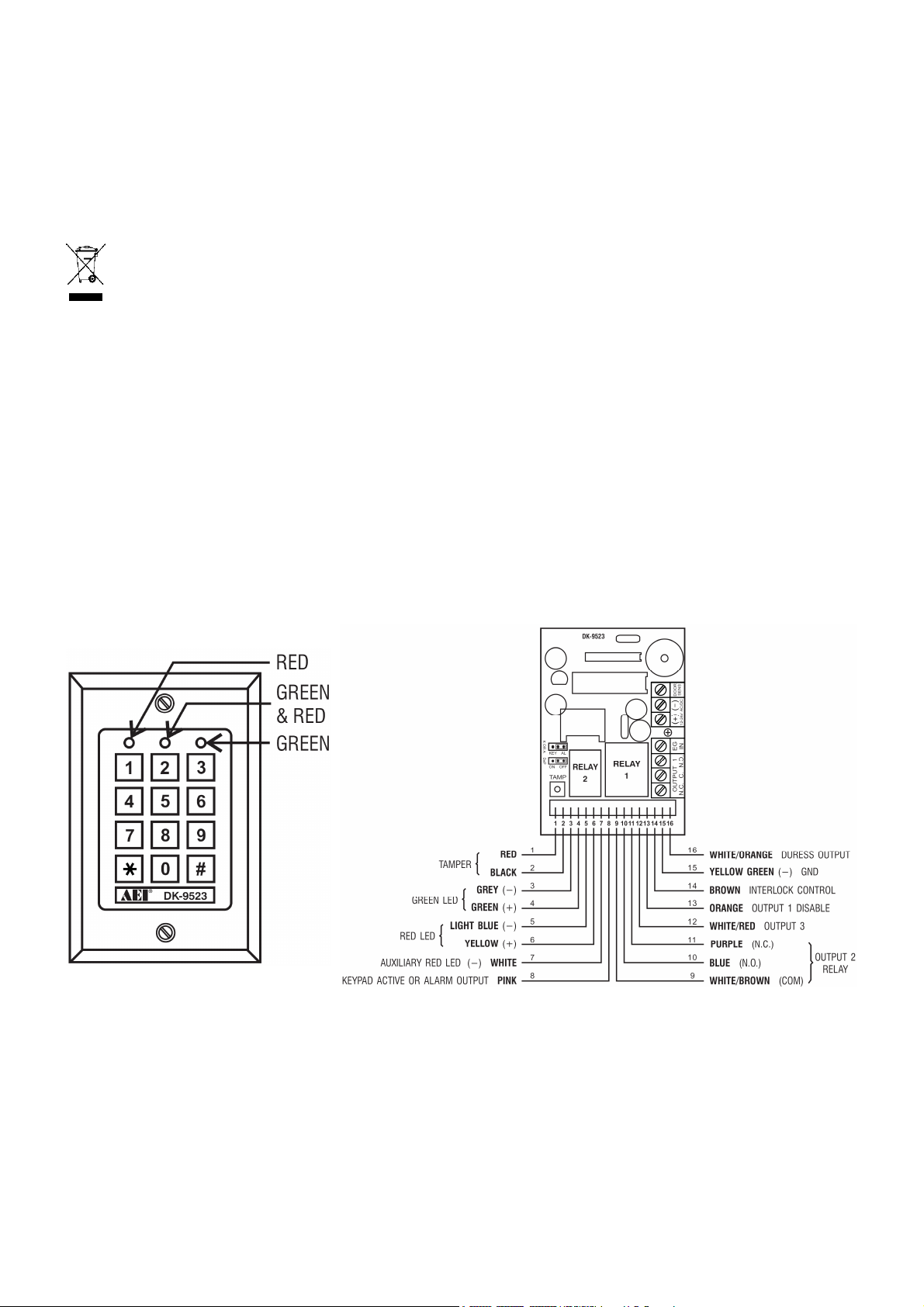
2. Connections (fig. 1)
THE LED INDICATORS
• RED & GREEN
The red and green LEDs are to be connected at the installer’s will.
• AUX RED / GREEN
The green LED is a status indicator at normal operation. The LED changes to steady red while the auxiliary red
LED is energized.
THE TERMINAL BLOCK
v2 15/11/2013 VELLEMAN
Page 3

HAA85BL
3
• OUTPUT 1
5A dry relay contacts, recommended for door strike controls. Normally Open (N.O.) and Normally Closed (N.C.)
outputs are available. Use N.O. output for fail-secure locking device and N.C. output for fail-safe locking device.
The relay can be programmed in start/stop (toggle) mode or timer mode from 1 to 999 seconds.
• EG IN (EGRESS INPUT)
A N.O. input terminal refers to (-) ground with the help of a N.O. button to deactivate the output 1. The egress
button is usually put inside the house near the door. More than one egress button can be connected in parallel to
the terminal. Leave this terminal open if it is not used.
• 12V-24V AC/DC (POWER INPUT)
Connect to 12V-24V AC/DC power supply. The (-) supply and GND (wire 15) are the common grounding points of
the keypad system. No selection jumper is required for the full input voltage range. Connect DC power with the (+)
and (-) polarity; there is no discrimination for the AC power input.
• DOOR SENS (DOOR POSITION SENSOR INPUT)
A N.C. input terminal referring to (-) ground. With the help of a N.C. magnetic door switch, the system will monitor
the position of the door and will give the following functions:
1.
Door Auto Relock
The system will immediately relock the door after valid access has been gained before the end of the
programmed time for output 1.
Door Forced Open Alarm
2.
The keypad will generate door forced-open alarm instantly if the door is forced open without a valid user entry
or egress input. The alarm will last for 60 seconds and can be stopped with user code 1 or one of the user
codes in group 1. This function is selectable via the programming options at location 801.
3.
Door Propped-Up Alarm
When the door is left open longer than the allowable time. The keypad will generate door propped-up alarm
after the expiry of the preset door opening time until the door is closed again. The door opening time is
programmable from 1 to 999 seconds at location 9.
Interlock Control
4.
The interlock control output goes to (-) while the door is open in order to give signal to disable the other
keypad in the interlock system.
THE WIRE HARNESS
NOTE: Always hold the PCB tightly and gently pull out the socket to prevent damage of the electronic assembly of
the keypad.
• N.C. TAMPER (1-2)
N.C. contact when the keypad is secured on the box. It is open when the keypad is separated from the box.
Connect the terminal to the 24-hour zone of an alarm system if necessary.
• GREEN, RED & AUXILIARY RED LEDs (3-4), (5-6) & (7)
Three on-board LED lamps are available. They are prepared for free connections. Connect these to the remote
indicator driving terminals of your equipment such as an alarm control panel. Mind the polarity.
The green and red lamps that are independent are equipped with 1.5k Ω current limiting resistor.
v2 15/11/2013 VELLEMAN
Page 4

HAA85BL
4
STATUS
TONES*
LED SIGNALS
1.
In programmable mode
- - - ON
2.
Successful key entry
1 beep
1 flash
3.
Successful code entry
2 beeps
2 flashes
4.
Unsuccessful code entry
5 beeps
5 flashes
5.
DAP jumper not replaced
Continuous beeps
Continuous flashes
6.
In standby mode
- - -
1 flash in 2
-
seconds interval
7.
Output relay activated
1-
second long beep
** - - -
The anode of the auxiliary red LED is connected to the +5V internally. It turns on with the cathode (wire 7)
connected to (-) ground.
• KEYPAD ACTIVE OUTPUT OR ALARM OUTPUT (8)
An NPN transistor open collector output with max. rating of 100mA sink and 24VDC. It is selectable to give
Keypad Active Output or Alarm Output via the K or A jumper.
1.
Keypad Active Output (KEY)
It switches to (-) ground for 10 seconds with each press of the key. This can be used to turn on lights, CCTV
cameras or buzzer.
Alarm Output (AL)
2.
Switches to (-) ground when the Door Forced Open Alarm or Door Propped-Up Alarm occurs in order to trigger
the external alarm to give notification at a remote location.
• OUTPUT 2 (9-10-11)
Auxiliary relay output with 1A N.O. and N.C. dry contacts controlled by user code 2 and ideal for controlling
security systems and automatic operators. It is programmable for start/stop (toggle) operation or timing operation
from 1 to 999 seconds.
• OUTPUT 3 (12)
An NPN transistor open collector output ideal for auxiliary control functions such as security systems. This output
is programmed for start/stop (toggle) operation or timing operation from 1 to 999 seconds. It switches to (-) ground
when active and the max. rating is 100mA sink / 24VDC.
• OUTPUT 1 DISABLE (13)
A N.O. input terminal refers to (-) ground. Neither user code 1 nor egress button can activate output 1 when this
terminal is tied to (-) ground. It is prepared for cross-wired connection in an interlock application.
• INTERLOCK CONTROL OUTPUT (14)
An NPN transistor open collector output. It is off at normal condition and switches to (-) ground immediately for the
first 5 seconds after keying in a valid user code to operate output 1. Then, it will keep tying to (-) during the time
that the door position sensor is open. Use this output to control the other keypad in an interlock system to prevent
both doors from opening at the same time.
• DURESS OUTPUT (16)
An NPN open collector output. It switches to (-) ground when the duress code is entered. Use it to trigger an
alarm zone or to turn on a buzzer to notify a guard. Ic max.: 100mA sink; Vc max.: 24VDC.
3. The Pacifier Tones & LED Indicating Signals
The built-in buzzer and the green LED indicator in the centre give the following tones and signals for operation status:
NOTE: * All pacifier tones can be enabled or disabled through programming options at location 83.
v2 15/11/2013 VELLEMAN
Page 5
HAA85BL
5
Entry of code
Validation
Comments
Entry of code
Validation
Comments
Set the system to single user mode, clear all previously stored
Set the system to
multi
-
user mode, clear all previously stored
Locations
Entry of codes
Validation
Comments
** The output activation beep can be enabled or disabled through programming options at location 82.
4. Reset master code
If you have forgotten the master code, you can reset it. For the master code, do not use a combination that is already
taken for a user code.
1. Disconnect power supply.
2. Displace the DAP jumper from OFF to ON.
3. Reconnect power supply (buzzer is activated).
4. Put the DAP jumper back to OFF position (this done, the buzzer is de-activated).
5. The Keypad is in programming mode and ready to receive your new programming data.
6. Enter a new 4-digit master code at location 0 in case you have forgotten the old master code.
7. Enter the new programming data starting from Section B) in the summary chart shown below.
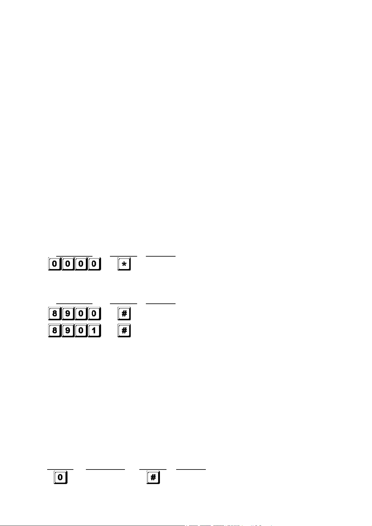
5. The Factory-Set Master Code – Important Note
When programming for the first time, the master code 0000 shall be used. In all cases, program a new master code
to invalidate the old master code and to ensure security.
6. Programming the Keypad – Summary Chart
A) Use the factory-set master code entry in programming -- When starting for first time only
Enter in programming mode by factory set master code
B) Set the system to single or multi-user mode and refresh the system – Installer programming
C) Record the personal master code and user codes – User programming
Notes: master code
• When programming the codes, it is recommended to program the master code before the user codes.
• If you are programming a new master code, do not use a combination that is already taken for a user code.
• If you have forgotten the master code, you can reset it. See section 4 Reset master code.
Notes: user code
• Any user code must be different from the master code.
• It is recommended to program a different code for every user.
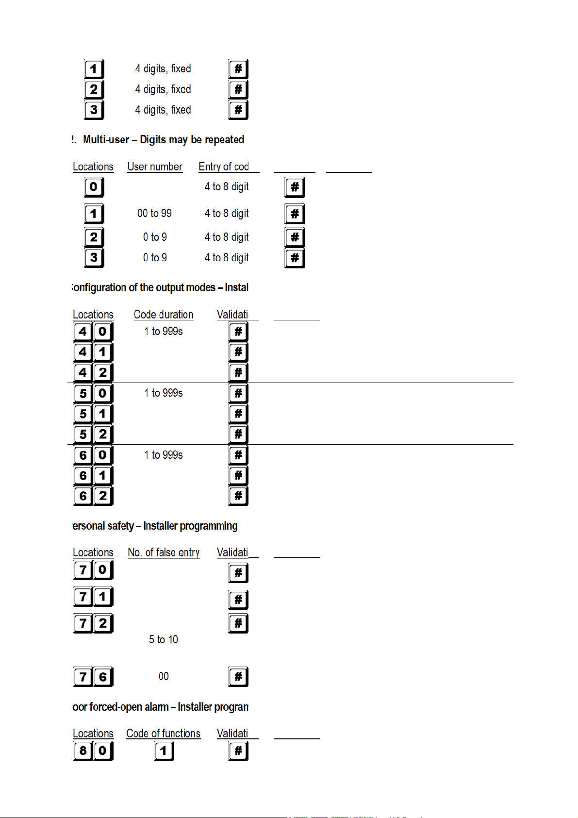
Single user – Digits may be repeated
1.
data and refresh system
data and refresh system
4 digits, fixed
v2 15/11/2013 VELLEMAN
Personal master code and super user code
Page 6
HAA85BL
6
Locations
User number
Entry of codes
Validation
Comments
Personal
master code and super user
100 user codes in group 1 for output 1 with
Locations
Code duration
Validation
Comments
Locations
No. of false entry
Validation
Comments
After 10 successive false codes, the keypad locks
After 10 successive false codes, the duress output
Selectable after 5 to 10 successive false codes, the
Locations
Code of functions
Validation
Comments
4 digits, fixed
4 digits, fixed
4 digits, fixed
User code 1 for output 1 with duress code function
User code 2 for output 2
User code 3 for output 3
2.
Multi-user – Digits may be repeated
4 to 8 digits
00 to 99 4 to 8 digits
0 to 9 4 to 8 digits
0 to 9 4 to 8 digits
D) Configuration of the output modes – Installer programming
1 to 999s
Output 1 momentary mode from 1 to 999 seconds
code
duress code function
10 user codes in group 2 for output 2
10 user codes in group 3 for output 3
1 to 999s
1 to 999s
E) Personal safety – Installer programming
5 to 10
Output 1 in start/stop mode (toggle)
Output 1 in start/stop mode w/ accelerated code
Output 2 momentary mode from 1 to 999 seconds
Output 2 in start/stop mode (toggle)
Output 2 in start/stop mode w/ accelerated code
Output 3 momentary mode from 1 to 999 seconds
Output 3 in start/stop mode (toggle)
Output 3 in start/stop mode w/ accelerated code
during 30 seconds
switches to ground
keypad locks during 15 minutes. The keypad can be
reset to release locking with the master code at any
time during the locking period.
00
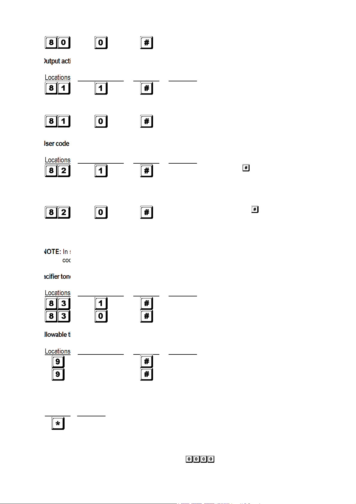
F) Door forced-open alarm – Installer programming
v2 15/11/2013 VELLEMAN
All of the above securities disappear
Door forced-open alarm is enabled
Page 7
7
Locations
Code of functions
Validation
Comments
1-second notifying beep is given to notify the person
Notifying beep disabled and replaced by 2 short
Locations
Code of functions
Validation
Comments
Locations
Code of functions
Validation
Comments
Locations
Code of functions
Validation
Comments
0
Allowable time from 1 to 999 seconds before door
Validation
Comments
G) Output activation announcer – Installer programming
HAA85BL
Door forced-open alarm is disabled
outside to open the door when the output relay is
activated with a user code or egress button. Good for a
locking device without sound such as a magnetic lock.
successful code entry beeps for valid user codes
H) User code entry mode (auto or manual) – Installer programming
Auto entry code is selected. key following the user
code is NOT required in code entry. The user code
MUST be set in the same digit length as the master
code in auto entry mode and the code length can be 4
to 8 digits long.
Manual entry mode is selected. key following the
user code is required in code entry. The user codes
can be 4 to 8 digits long and they are not required to
be the same length as the master code.
NOTE: In single user mode, no matter the selection (auto or manual mode), the master code and the user
code MUST be set as a 4-digit number.
I) Pacifier tones (keypad acknowledgement tones) – Installer programming
Pacifier tones available on the keypad
All pacifier tones are off.
J) Allowable time to start door propped-up alarm – Installer programming
No propped-up alarm
1 to 999
propped-up alarm starts
K) Exit programming mode
Exit programming mode and return to normal operation
7. Single User or Multi-User Mode Selection
The HAA85BL has been factory-set in single user mode with as master code.
v2 15/11/2013 VELLEMAN
Page 8
HAA85BL
8
Default
Comments
Default
Comments
401 Output 1 in 1
-
second
momentary
811 Output relay activation beep on
501 Output 2 in 1
-
second momentary
820 User code manual entry mode* (multi
-
601 Output 3 in 1
-
second momentary
821 User code auto entry mode* (single
70 After 10 successive false
code
s
, the
831 Pacifier tones on
800 Door forced
-
open alarm disabled
90
No propped
-
up alarm
MASTER
Single user mode enabled. Wait 2
-
3 seconds after
Single user mode (command code: 8900)
Each output can only be operated by one user code. The user code must be 4 digits long. There are 10 000
possible code combinations. The code can be programmed directly into the user code locations 1, 2 and 3
respectively for the 3 outputs. Refer to “6. C) 1. Single user – Digits may be repeated” for more details. This
mode is always set with auto code entry in default. You do not need to press in user code entry. Only enter the
4-digit user code.
NOTE: The system can be set for manual code entry with programming option 0 at location 82 if necessary.
Multi-user mode (command code: 8901)
Up to 100 individual codes will operate output 1 and 10 individual codes will operate output 2 and 3. The user
code can be 4 to 8 digits long. There are over 100 million possible code combinations. The user codes can be set
for auto or manual entry with programming options at location 82. Default mode is manual entry mode. Pressing
after code entry is required. Once the keypad is programmed in auto entry, the master code and the user
codes MUST consist of the same number of digits. Do not press after entering the user code.
Default values
mode
mode
mode
user)
user)
keypad locks during 30 seconds
NOTE: * All default values in multi-user and single user mode are exactly the same except the user code entry
mode.
Code entry limitation in multi-user mode due to duress code
The system comes with duress function for user code 1 in single user mode and all the user codes of group 1 in
multi-user mode. The duress code is automatically set by the system by taking the first digit of the user code and
adding or subtracting 2. To prevent other codes falling in the duress code, the first digit of a stored user code +2
or -2 is not allowed as a later user code entry.
Example: User code 56789 was stored in the system. User codes 36789 and 76789 are not allowed.
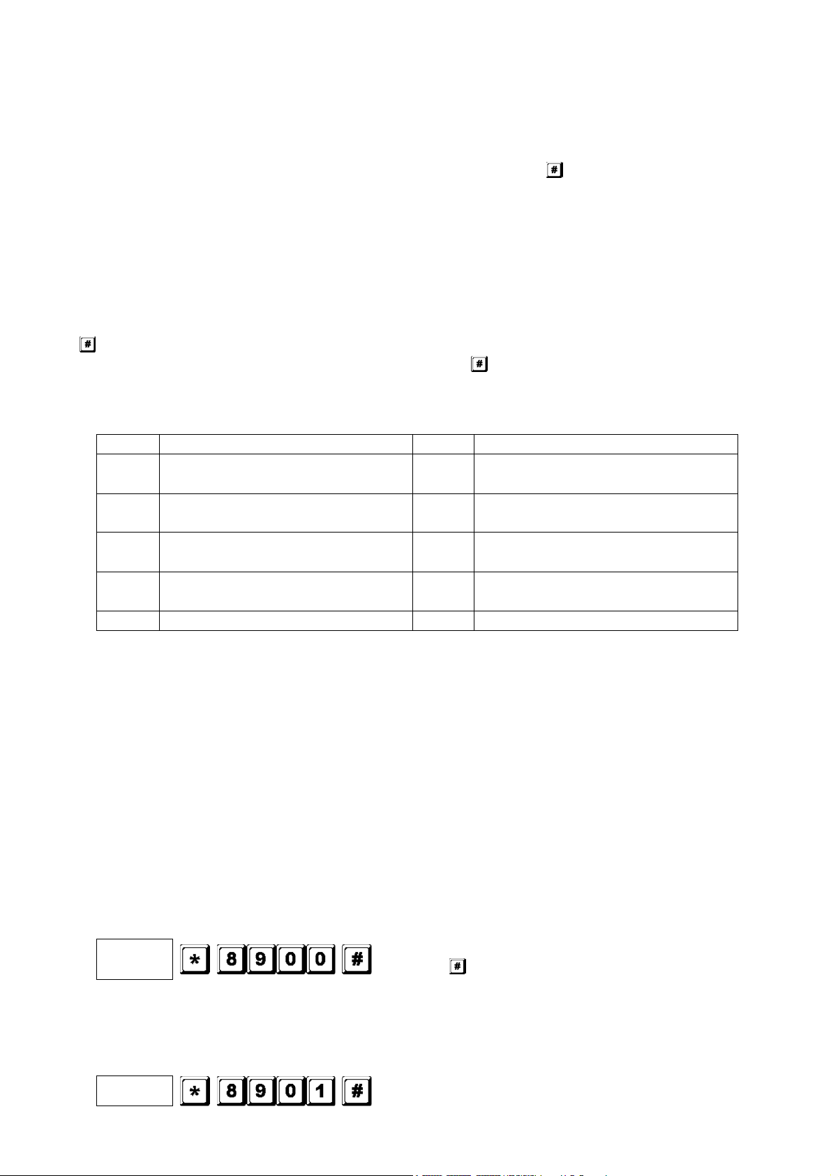
Set the system to single user mode
Set the system to single user mode with the command code 8900. The system will stay in that mode until it is
refreshed. Make sure the master code is 4 digits long.
CODE
Set the system to multi-user mode
Set the system to multi-user mode with the command code 8901. The system will stay in that mode until it is
refreshed.
MASTER
v2 15/11/2013 VELLEMAN
pressing until you hear confirmation beeps.
Multi-user mode enabled. Wait 2-3 seconds after
Page 9
HAA85BL
9
CODE
…
pressing until you hear confirmation beeps.
Refreshing the system
When choosing a different operation mode (see above), the system will reset and clear all values except for the
master code.
NOTE: Make sure the user code and the master code are both 4 digits long when operating in single user mode.
8. Programming and Use of the Keypad – Operation Examples
A) Programming procedures
Your HAA85BL is programmed from the keypad. All programmed information is stored in the non-volatile
a.
memory.
b.
Set the keypad into programming mode first with the master code and press to validate.
NOTE: Use the DAP jumper to set the keypad into programming mode in case you forgot the master code.
See section 4 Reset master code.
c.
Go to a location and program the options. See “6. Programming the Keypad – Summary Chart”.
d. Program the options until all options are programmed. Repeat the programming of an option in case of a
wrong entry.
LOCATION 1 OPTION
LOCATION n OPTION n
e.
Exit the programming mode with . All input information has been saved.
B) Single user mode operation – Example
Requirements
1.
a.
Single user mode
b.
Change the factory-set master code 0000 to a personal master code 3289
c.
Set user code 1 to 8321
Set user code 2 to 6854
d.
e.
Set user code 3 to 9270
f. Set output 1 to momentary mode, 1 second
Set output 2 to start / stop mode
g.
h. Set output 3 to start / stop mode
i.
Set the keypad to lock itself during 15 minutes after 10 successive false codes
2.
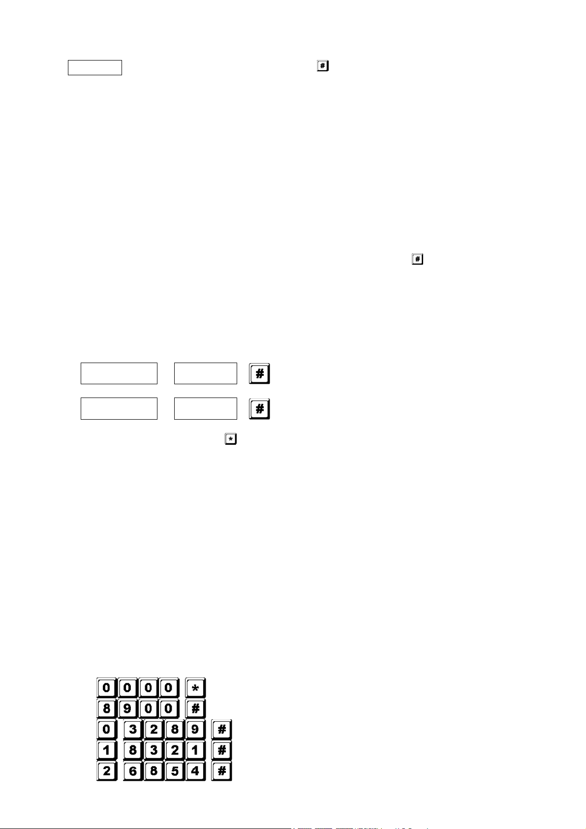
Programming – Setting the above requirements into the keypad
Program mode with factory-set master code
Single user mode*
3289 stored as new personal master code and super user code
8321 stored as user code1 with duress code function for output 1
6854 stored as user code 2 for output 2
v2 15/11/2013 VELLEMAN
Page 10

HAA85BL
10
Keypad set to lock during 15 minutes after 10 successive false
Duress
output
activates
(output switches to (
-
) ground) and
9270 stored as user code 3 for output 3
Output 1 set as momentary mode, 1 second
Output 2 set to start / stop mode
Output 3 set to start / stop mode
codes
Exit programming mode. All above data stored and ready for use
NOTE: * Entering single user command code 8900 is not necessary if the keypad was already in single
user mode.
Cancel a wrong entry with or wait 10 seconds and retry.
3.
Operating the keypad – Taking the data programmed above and other default features as reference
To command an output, only enter the user code. Pressing is not required.
a.
Output 1 activates for 1 second
Output 2 starts or stops
Output 3 starts or stops
The personal master code is a super user code to command the outputs. This feature allows you to use
b.
only one code to operate several keypads with the same master code but different user codes. Enter
the personal master code and validate with and the corresponding output number.
Output 1 activates for 1 second
Output 2 starts or stops
Output 3 starts or stops
c.
The duress code does not need to be programmed. The keypad automatically determines the duress
code by increasing the first digit of user code 1 with two units.
Example: If user code 1 is 1234, then the duress code will be 3234. If user code 1 is 8321, then the
duress code will be 0321.
To command the duress function, enter the duress code.
output 1 activates for 1 second
NOTE: The duress code has 2 functions: it activates the duress output and at the same time it activates
output 1 as user code 1. The duress code can always activate or deactivate (in start / stop mode)
output 1, but cannot deactivate (reset) the duress output.
d.
The accelerated code is the first two digits of the user code. If output 1 has been programmed in start /
stop mode with accelerated code at location 42, it will be possible to activate output 1 with only the first
two digits of the user code. Deactivation always requires the composition of the complete user code.
Example: Output 1 has been reprogrammed to start / stop mode with accelerated code (location 42).
Complete code: 8321, accelerated code: 83.
v2 15/11/2013 VELLEMAN
Page 11
11
3289 stored as new personal master code and
8321 stored as 1
st
user code in group 1 with
11223 stored as the 2
nd
user code in group 1 with
33221 stored as the 3
rd
user code in group 1 with
Keypad set to lock during 15 minutes after 10
Try and enter some random false codes to test the safety. The HAA85BL will consider 4 digits as one
e.
code and generate 5 beeps for each unsuccessful code entry. The keypad will lock itself during 15
minutes after 10 successive false codes. The keypad can be reset during the locking period by entering
the master code.
C) Multi-user mode operation – Example
Requirements
1.
a.
Multi-user mode
b. Change the factory-set master code 0000 to a personal master code 3289
st
Set 1
c.
d.
Set 2
e.
Set 3
f. Set 1
Set 2
g.
h. Set 1
i.
Set output 1 to momentary mode, 1 second
Set output 2 to start / stop mode
j.
user code in group 1 to 8321
nd
user code in group 1 to 11223
rd
user code in group 1 to 33221
st
user code in group 2 to 6854
nd
user code in group 2 to 54321
st
user code in group 3 to 9270
k. Set output 3 to start / stop mode
l.
Set the keypad to lock itself during 15 minutes after 10 successive false codes
2.
Programming – Setting the above requirements into the keypad
HAA85BL
Output 1 starts
Output 2 stops
Locking is reset and keypad resumes normal operation
Program mode with factory-set master code
Multi-user mode*
super user code
duress code function
duress code function
duress code function
6854 stored as the 1st user code in group 2
54321 stored as the 2nd user code in group 2
9270 stored as the 1st user code in group 3
Output 1 set to momentary mode, 1 second
Output 2 set to start / stop mode
Output 3 set to start / stop mode
successive false codes
v2 15/11/2013 VELLEMAN
Page 12

HAA85BL
12
Exit programming mode. All above data stored and
Example:
User codes in group 1
Corresponding duress codes
8321
0321
11223
31223
33221
53221
Duress
output
activates (output switches to ground) and output 1
Duress output activates (output switches to ground) and output 1
ready for use
NOTE: * Entering single user command code 8901 is not necessary if the keypad was already in single
user mode.
Cancel a wrong entry with or wait 10 seconds and retry.
Operating the keypad – Taking the data programmed above and other default features as reference
3.
a.
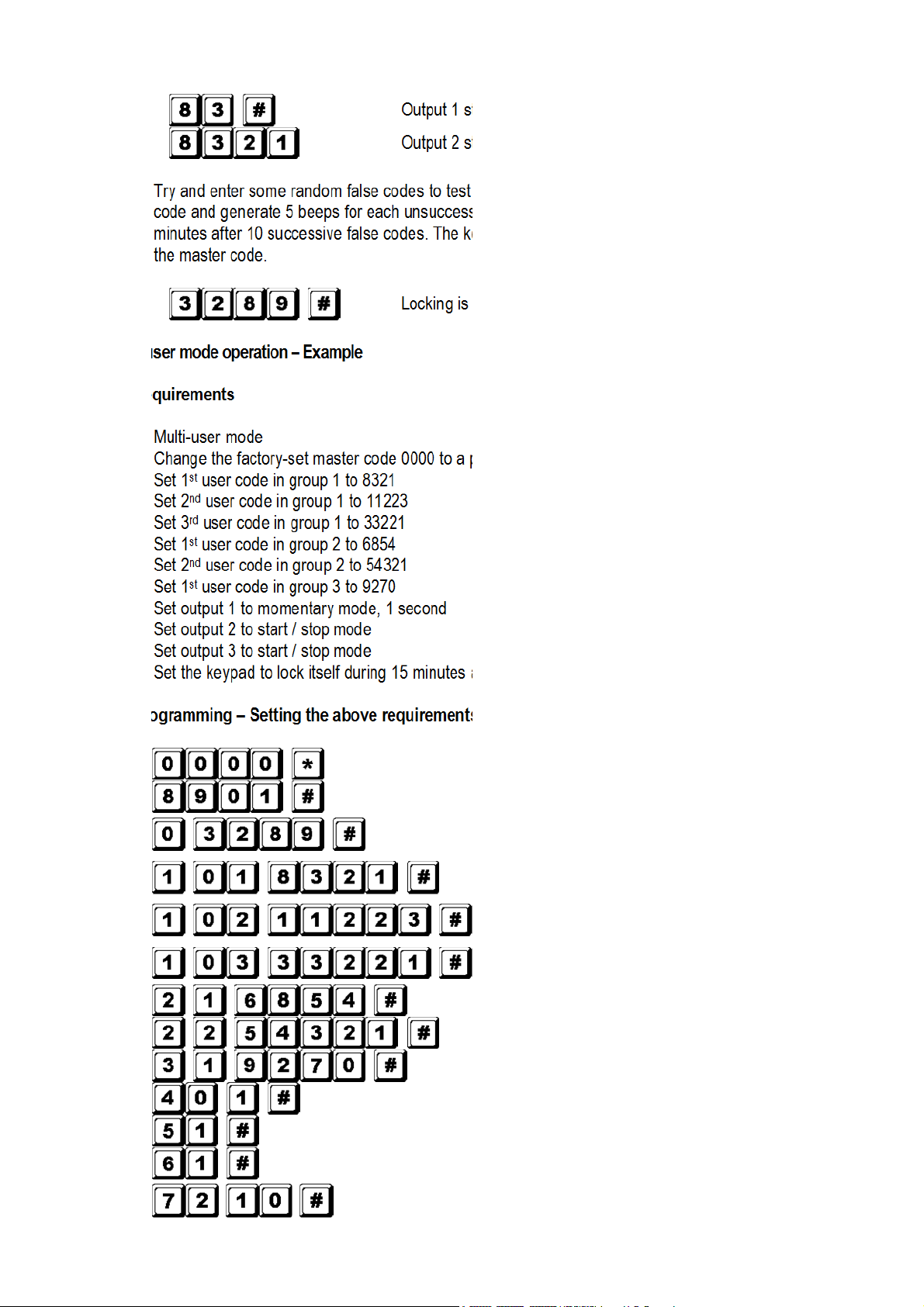
To command output 1, enter one of the user codes in group 1 and validate with .
Output 1 activates for 1 second
Output 1 activates for 1 second
Output 1 activates for 1 second
To command output 2, enter one of the user codes in group 2 and validate with .
b.
Output 2 starts or stops
Output 2 starts or stops
To command output 3, enter one of the user codes in group 3 and validate with .
c.
Output 3 starts or stops
The personal master code is a super user code to command the outputs. This feature allows you to use
d.
only one code to operate several keypads with the same master code but different user codes. Enter
the personal master code and validate with and the corresponding output number.
Output 1 activates for 1 second
Output 2 starts or stops
Output 3 starts or stops
The duress code does not need to be programmed. The keypad automatically determines the duress
e.
code by increasing the first digit of user codes in group 1 with two units. All user codes have duress
code function.
To command the duress function, enter the duress code(s).
v2 15/11/2013 VELLEMAN
activates for 1 second
activates for 1 second
Page 13
HAA85BL
13
Duress output activates (output switches to
ground) and output 1
activates for 1 second
NOTE: The duress code has 2 functions: it activates the duress output and at the same time it activates
output 1 as user code in group 1. The duress code can always activate or deactivate (in start /
stop mode) output 1, but cannot deactivate (reset) the duress output. Only the user codes in
group 1 can deactivate (reset) the duress output.
The accelerated code is the first two digits of the user code(s). If the output has been programmed in
f.
start / stop mode with accelerated code (programming option 42 for user codes in group 1 and
programming option 52 for user codes in group 2), it will be possible to activate the output with only the
first two digits of the user code(s). Deactivation always requires the composition of the complete user
code(s) in their code group.
Example: Output 1 has been reprogrammed to start / stop mode with accelerated code (location 42).
Complete code of the 1
st
user code in group 1: 8321, accelerated code: 83.
2nd user code in group 1: 11223, accelerated code: 11.
Output 1 starts
Output 1 stops
Output 1 starts
Output 1 stops
Try and enter some random false codes to test the safety. The HAA85BL generates 5 beeps for each
g.
unsuccessful code entry. The keypad will lock itself during 15 minutes after 10 successive false codes.
The keypad can be reset during the locking period by entering the master code.
Locking is reset and keypad resumes normal operation
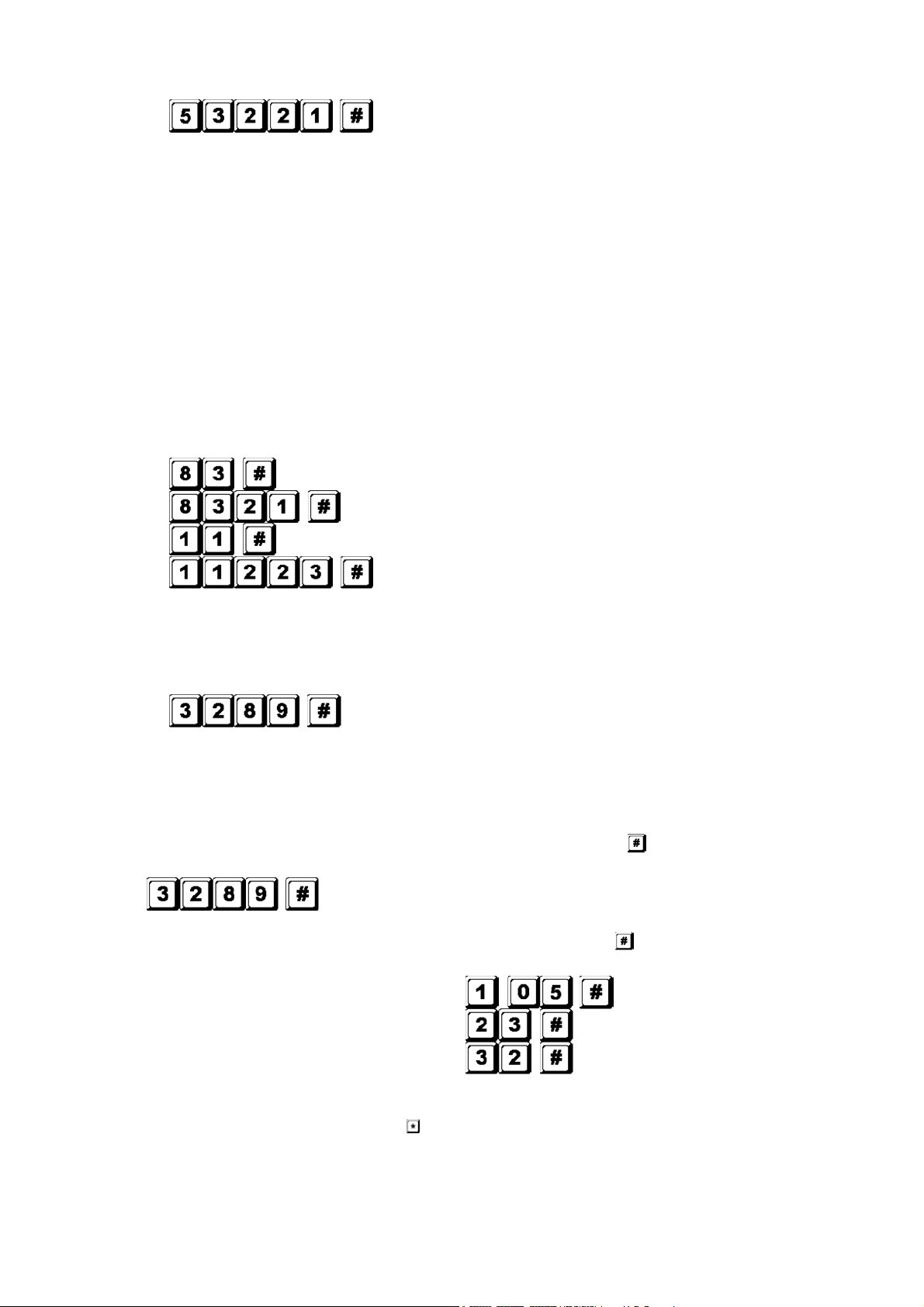
D) Deleting a user in multi-user mode
If you need to delete a user who no longer has authority to enter the protected area:
Set the system in programming mode with the personal master code and .
1.
Keypad is in programming mode
Enter the user number (00~99 for output 1; 0~9 for output 2 and 3) and to delete a user code.
2.
To delete user number 05 in group 1, press
To delete user number 3 in group 2, press
To delete user number 2 in group 3, press
3.
Continue deleting desired codes.
4. Exit the programming mode by pressing .
7. Technical Specifications
• Operation Voltage
v2 15/11/2013 VELLEMAN
Page 14
HAA85BL
14
12V-24V AC/DC, no jumper required for voltage selection
• Operation Modes
Single user mode, auto or manual code entry
a)
b) Multi-user mode: 100 user codes for output 1 (user number 00-99), auto or manual code entry
10 user codes for output 2 (user number 0-9), auto or manual code entry
10 user codes for output 3 (user number 0-9), auto or manual code entry
• User Code Combinations
a)
Single user mode: 10 000
b) Multi-user mode: 111 110 000
• Input Sensing Terminals
a)
Egress input: N.O. referring to (-) ground
Door position sensor input: N.C. referring to (-) ground
b)
c)
Relay 1 stop control: N.O. referring to (-) ground
• Relay Output Contacts
OUTPUT 1: N.C. and N.O. dry contacts, 5A / 30VDC max. rating
OUTPUT 2: N.C. and N.O. dry contacts, 1A / 30VDC max. rating
OUTPUT 3: NPN open collector, 100mA sink / 24VDC max.
• Tamper Switch Contact
N.C. dry contact, 50mA max.
• Duress, Interlock and Key-Active Output Rating
NPN open collector switches to ground when active, 24DC / 100mA sink
• Auto Refreshing Time during Code Entry
Each digit max. entry time limit: 10 seconds
a)
b) Each code max. entry time limit: 30 seconds
• Dimensions
117 x 74 x 48mm
• Weight
180g
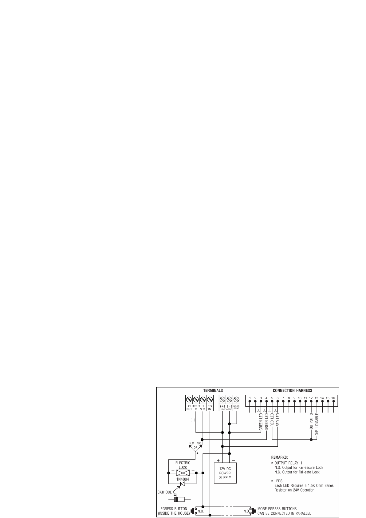
8. Application Examples
1.
Basic wirings of a stand-alone door
lock with inhibit authorization code
and indication (fig. 2)
• Connect the 1N4004 as close as
possible to the lock in parallel with
the lock power terminals in order to
absorb the back EMF and to prevent
it from damaging the keypad. The
1N4004 is not required if the electric
lock is AC-operated.
v2 15/11/2013 VELLEMAN
Page 15
HAA85BL
15
• To avoid electrostatic discharges, always ground the (-) terminal of the keypad to earth.
• The green LED lights while the keypad is striking the electric lock.
• The connection “output 3” to “output 1 disable” is optional. With this connection, output 3 will be used as an
authorization control. You may key in user code 3 to stop the operation of the electric lock during daytime or
after office hours in order to prevent unauthorized access. Set output 3 in start / stop mode (programming
option 61) for on / off control. The red LED lights when the operation of the electric lock stops.
• Tape all unused wires to prevent short-circuit.
WARNING: For safety, make sure everybody has left the building before enabling the door lock inhibit
function. Only the owner should keep the inhibit authorization code.
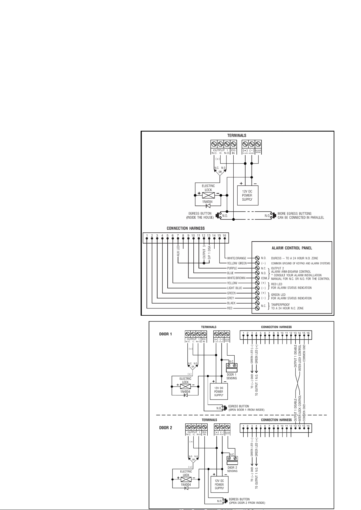
2.
Basic wirings for alarm arm-disarm and stand-alone door lock (fig. 3)
• This application is the same as
application 1 except for the
LED indications. The green and
red LEDs are used as alarm
status indications, such as exit,
armed, alarm memory, etc.
• Relay output 2 is used for the
alarm arm-disarm control.
Refer to the manual of your
alarm control panel.
• Connect the tamper switch to
the N.C. 24-hour zone and the
duress output to the N.O. 24hour zone for tamperproof and
emergency reporting.
• The connection “output 3” to
“output 1 disable” is optional.
With this connection, output 3
will be used as an authorization
control. You may key in user
code 3 to stop the operation of
the electric lock at light or after
office hours in order to prevent
unauthorized access. Set output 3
in start / stop mode (programming
option 61) for on / off control. The
red LED lights when the operation
of the electric lock stops.
• The yellow green wire is the
common ground to link up the
keypad and the alarm control
panel in order to achieve the
logical functions.
Basic wirings of an interlock
3.
system using 2 keypads (fig. 4)
An interlock system needs 2 door
controllers. This application uses 2 x
HAA85BLs with a simple crosswire
v2 15/11/2013 VELLEMAN
Page 16
HAA85BL
16
connection on “output 1 disable” and “interlock control output” terminals of both keypads. Link up the (-) GND
terminals of both keypads as common ground in order to achieve the interlock functions. Connection of the
green LED is optional. It will light up when the lock is active when connected.
• Use the keypad to open the door from the outside.
• Press the egress button to open the door from the inside.
• Connect the magnetic sensors on door 1 and 2.
• During the time that door 1 is open, door 2 is forced to keep closed and vice versa.
• Use the N.O. relay output for fail-secure locking device and the N.C. output for fail-safe locking device.
• Relay output 2 is independent and has no concern with the interlock system. It may be used for other
applications.
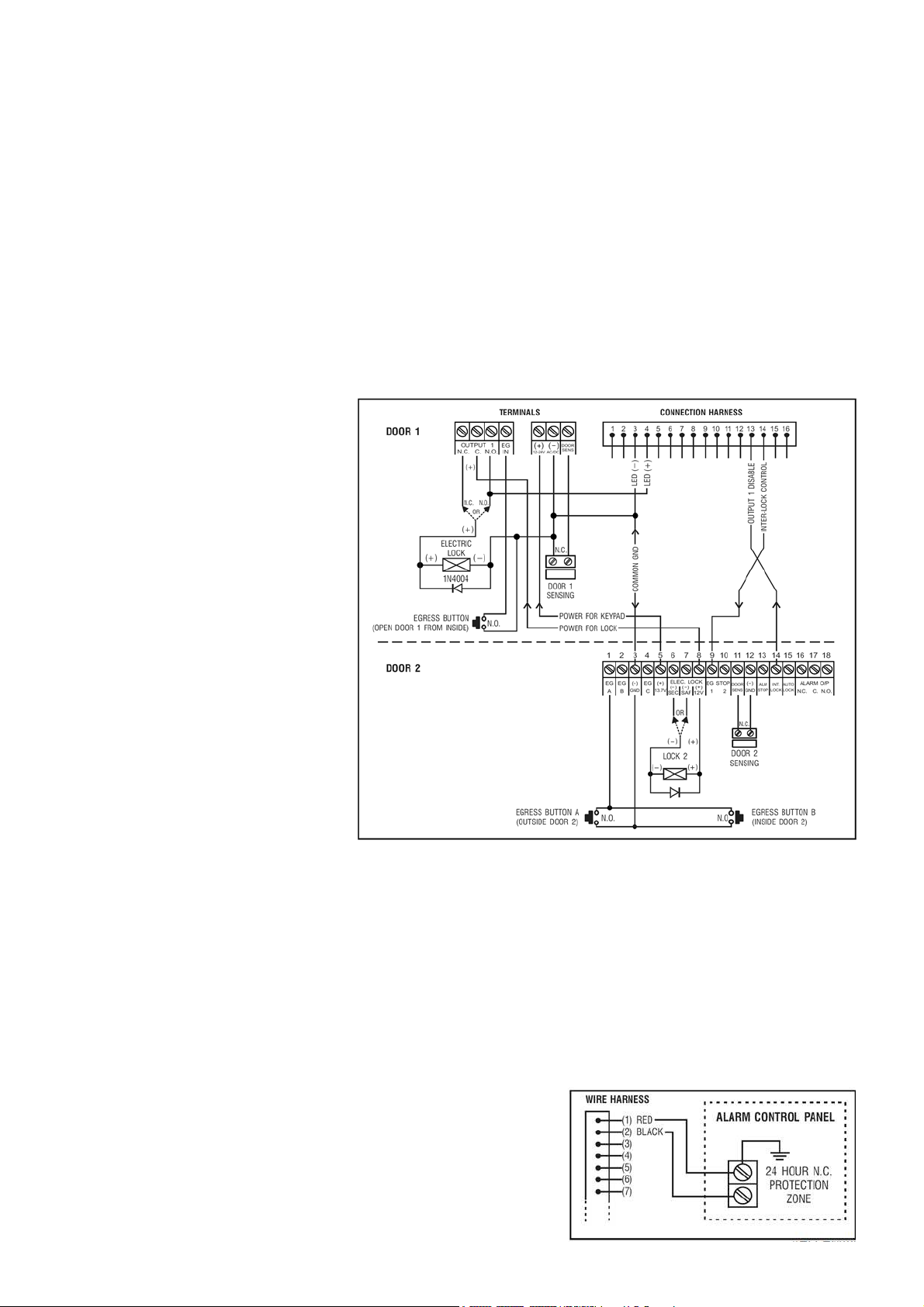
Basic wirings of an interlock system using 1 keypads and an interlock controller power supply (fig. 5)
4.
This application uses one
HAA85BL and a power supply
with interlock controller. The
power supply provides power for
the whole system, including both
electric locks and the keypad.
Make sure the total power
consumption of the system does
not exceed the maximum power
ratings of the power supply,
especially if fail-safe locks are
used. The interlock function is
accomplished with a crosswire
connection of the “interlock
control output” and the “output 1
disable” terminals between the
keypad and the controller. Link up
a common ground between the
keypad and the power supply to
set up a power path and to
achieve the interlock functions.
• Use the keypad to open door 1 from the outside.
• Open door 2 with egress button A from the outside while door 1 is closed.
• Open door 1 from the inside with the egress button and open door 2 with egress button 2.
• Connect the magnetic sensors on door 1 and 2.
• During the time that door 1 is open, door 2 is forced to keep closed and vice versa.
• Use the N.O. relay output for fail-secure locking device and the N.C. output for fail-safe locking device.
• Relay output 2 is independent and has no concern with the interlock system. It may be used for other
applications.
9. Application Examples for the Auxiliary Facilities
(A) Tamper N.C. (fig. 6)
The tamper switch is N.C. while the keypad is secured on the
gang box. To prevent sabotage, connect these terminals in series
with a N.C. 24-hour protection zone of an alarm if required.
v2 15/11/2013 VELLEMAN
Page 17

17
Door sens (fig. 7)
(B)
With the help of a N.C. door position sensor (usually a
magnetic door switch) on the door to set up the following
functions: door auto relock, door forced-open alarm, door
propped-up alarm and interlock control (see “2.
Connections”)
Key active – Pink wire (fig. 8)
(C)
HAA85BL
The key-active output will switch to (-) ground for 10 seconds whenever a key is pressed. Use it to turn on an
LED lamp and/or a small buzzer to notify a guard, to energize a relay to switch on lights or a CCTV camera…
• Make sure that the relay for switching on the lights has enough isolation between the high-voltage and low-
voltage to prevent damage to the keypad.
• Only one connection option is recommended. Make sure the sink current does not exceed the maximum
rating of 100mA.
• External power supply and isolation relay are necessary for driving high-power devices such as lights.
Duress output – White/orange wire (fig. 9)
(D)
The duress output will switch to (-) ground when the duress code is entered. You may use it to turn on an LED
lamp and/or a small buzzer. Connect it to a N.C. 24-hour protection zone of an alarm system.
• Only one connection option is recommended. Make sure the sink current does not exceed the maximum
rating of 100mA.
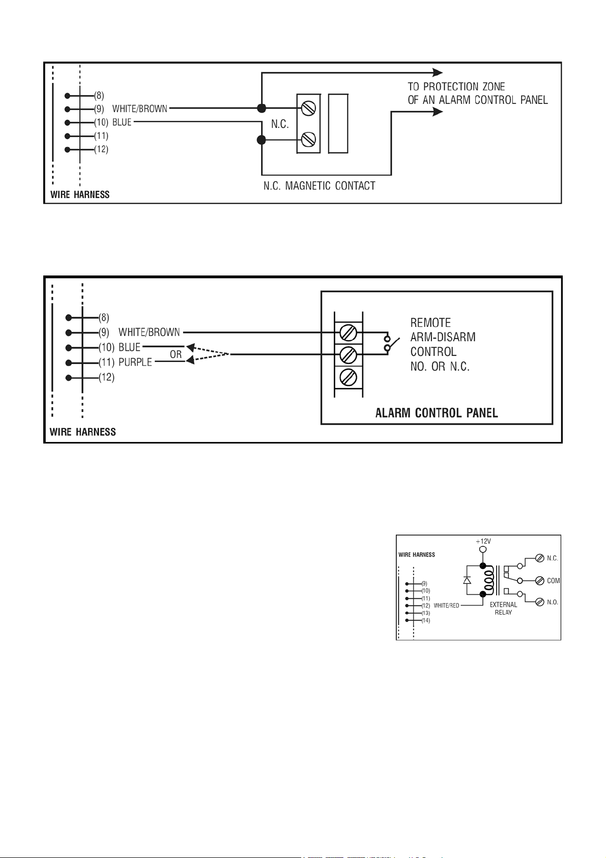
(E)
Output 2
1. Shunting an N.C. zone (white/brown and blue wires) (fig. 10)
v2 15/11/2013 VELLEMAN
Page 18
HAA85BL
18
• Use the N.O. output contact to shunt a N.C. protection zone of an alarm system.
• Set the output contact to start / stop mode (programming option 51).
Alarm system arm-disarm control (white/brown and blue or purple wires) (fig. 11)
2.
• Use the N.O. or the N.C. output contact to set the alarm system in arm-disarm mode.
• Refer to the manual of your alarm control panel for the appropriate output contact to be used in arm-
disarm control.
• Usually set output 2 to momentary mode (programming option 501) for multi-station systems and
start / stop mode (programming option 51) in single-station systems.
Output 3 (white/red wire) (fig. 12)
(F)
Output 3 is an open collector output prepared for auxiliary controls. It
may be used for arm-disarm of a security system, enabling and
disabling of a keypad or a protection zone, etc. It can also drive a relay
to give full function of N.C. and N.O. outputs.
For more info concerning this product, please visit our website www.velleman.eu.
The information in this manual is subject to change without prior notice.
v2 15/11/2013 VELLEMAN
Page 19

HAA85BL
19
GEBRUIKERSHANDLEIDING
1. Inleiding en kenmerken
Aan alle ingezetenen van de Europese Unie
Belangrijke milieu-informatie betreffende dit product
Dit symbool op het toestel of de verpakking geeft aan dat, als het na zijn levenscyclus wordt weggeworpen,
dit toestel schade kan toebrengen aan het milieu.
Gooi dit toestel (en eventuele batterijen) niet bij het gewone huishoudelijke afval; het moet bij een
gespecialiseerd bedrijf terechtkomen voor recyclage.
U moet dit toestel naar uw verdeler of naar een lokaal recyclagepunt brengen.
Respecteer de plaatselijke milieuwetgeving.
Hebt u vragen, contacteer dan de plaatselijke autoriteiten inzake verwijdering.
Dank u voor uw aankoop! Lees deze handleiding grondig voor u het toestel in gebruik neemt. Werd het toestel
beschadigd tijdens het transport, installeer het dan niet en raadpleeg uw dealer.
De HAA85BL is een onafhankelijk en betrouwbaar beveiligingstoetsenbord (met achtergrondverlichting) aan een
zacht prijsje en kan gebruikt worden in zowel woningen als bedrijven. Dit toetsenbord is compatibel met vrijwel elk
elektronisch slot in beveiligingssystemen, automatische schakelingen en machines. Er zijn meer dan 100 miljoen
combinaties mogelijk voor de gebruikerscodes (multi-usercode). De gegevens worden in een niet-vluchtig geheugen
bewaard. Enkel voor gebruik binnenshuis.
Toetsenbord met achtergrondverlichting: zwak in stand-by, sterk gedurende 10 seconden na indrukken van een toets.
2. Aansluitingen (zie fig. 1)
DE LED-AANDUIDINGEN
• ROOD & GROEN
Verbind de rode en de groene leds naar goeddunken.
• AUX ROOD / GROEN
De groene led is een statusaanduiding tijdens de normale werking. De led verandert naar vast rood terwijl de
AUX rode led wordt geactiveerd.
HET AANSLUITBLOK
• OUTPUT 1
5A droog relaiscontact voor een deurschakelaar. Normaal open (N.O.) en normaal gesloten (N.C.) uitgangen zijn
verkrijgbaar. Gebruik de N.O.-uitgang voor een slot in arbeidsstroom (fail-secure) en een N.C.-uitgang voor een
slot in ruststroom (fail-safe). Het relais kan worden geprogrammeerd in start-stopmodus (schakeling) of
timermodus van 1 tot 999 seconden.
• EG IN (EGRESS-ingang)
Een N.O.-ingangsterminal wordt aangesloten op de (-) aarding door middel van een N.O.-toets om relaisuitgang 1
te deactiveren. De egress-toets wordt doorgaans binnenshuis naast de deur geplaatst. U kunt meer dan één
egress-toets parallel aan de terminal aansluiten. Laat de aansluiting open wanneer u deze niet gebruikt.
• 12V-24V AC/DC (VOEDINGSINGANG)
Sluit een 12V-24V AC/DC voeding aan. De (-) klem en de GND (aarding, kabel 15) zijn gemeenschappelijke
aardingspunten. Er is geen brug nodig voor het gehele bereik van de ingangsspanning. Verbind de gelijkspanning
met de (+) en de (-); er is geen onderscheid voor de wisselspanning.
v2 15/11/2013 VELLEMAN
Page 20

HAA85BL
20
• DOOR SENS (INGANG VAN DE DEURSENSOR)
Een N.C.-ingangsterminal aangesloten op de (-) aarding. Samen met een N.C. magnetische deurschakelaar zal
het systeem de stand van de deur bepalen en volgende functies geven:
1. Automatische deurvergrendeling
Het systeem vergrendelt automatisch de deur na het ingeven van een geldige code vóór het einde van de
programmeertijd voor uitgang 1.
2. Alarm bij geforceerde deur
Het systeem genereert onmiddellijk een alarmsignaal wanneer de deur wordt geforceerd zonder een geldige
gebruikerscode of egress-ingang. Het alarmsignaal duurt 60 seconden en kan worden onderbroken met
gebruikerscode 1 of één van de gebruikerscodes in groep 1. Deze functie is selecteerbaar via de
programmeeropties op locatie 801.
3. Alarm bij open deur
Alarm wanneer de deur langer dan de toegestane tijd open blijft staan, m.a.w. het alarm gaat af na het
verlopen van de ingestelde tijd tot de deur opnieuw wordt gesloten. De tijd is instelbaar van 1 tot 999
seconden op locatie 9.
4. Sassysteem
Aansluiting op (-) terwijl de deur open is zodat het signaal wordt gegeven om de andere deur van het
sassysteem te openen.
DE KABELBOOM
OPMERKING: Houd de printplaat stevig vast en trek voorzichtig aan de plug zodat u de elektronica niet beschadigd.
• N.C. TAMPER (1-2)
N.C.-contact wanneer het toetsenbord aan de doos bevestigd is. Het wordt geopend wanneer het frontpaneel van
de doos verwijderd wordt. Sluit deze uitgang in serie aan de 24-uur noodschakeling op uw alarmsysteem indien
gewenst.
• GROENE, RODE & AUX RODE LEDS (3-4), (5-6) & (7)
Er zijn 3 leds op het paneel voorhanden. Ze werden voorbereid om er om het even welke functie op aan te sluiten.
Wij stellen voor om deze leds aan de indicatieaansluitingen van uw alarmcontrole paneel aan te sluiten. Houd de
juiste polariteit in het oog.
De groene en de rode onafhankelijke leds zijn voorzien van een 1.5k Ω stroombeperkende weerstand.
De anode van de AUX rode led wordt intern aangesloten op de +5V en wordt ingeschakeld met de kathode (kabel
7) aangesloten op de (-) aarding.
• ACTIEVE UITGANG OF ALARMUITGANG (8)
Opencollectoruitgang van een NPN transistor van max. 100mA sink en 24VDC. Selecteerbaar via de K- of Ajumper voor de actieve uitgang of alarmuitgang.
1.
Actieve uitgang (KEY)
Schakelt gedurende 10 seconden naar de (-) aarding bij elke druk op de toets. Wordt gebruikt voor het
inschakelen van verlichting, CCTV-camera’s of zoemers.
Alarmuitgang (AL)
2.
Schakelt naar de (-) aarding wanneer het alarm bij geforceerde of open deur afgaat. Zo wordt een extern
alarm ingeschakeld.
• UITGANG 2 (9-10-11)
v2 15/11/2013 VELLEMAN
Page 21
HAA85BL
21
STATUS
SIGNAAL
* LED
-
SIGNAAL
1. In programm
eerbare
modus - - - ON
2.
Toets is goed ingedrukt
1 pieptoon
1 fl
its
3.
Code is juist ingetoetst
2 pieptonen
2 fl
itsen
4.
Code is fout ingetoetst
5 pieptonen
5 flitsen
5. DAP jumper
niet opnieuw geplaatst
Continu
e pieptonen
Continu
e flitsen
6. In stand
-
by mod
us - - - 1
flits
in
interval van
2 seconden
7.
Relaisuitgang ingeschakeld
Pieptoon van 1 seconde**
- - -
Supplementaire relaisuitgang met 1A N.O. en N.C. droge contacten sie met gebruikerscode 2 worden
aangestuurd. Ideaal voor het aansturen van veiligheidssystemen en automatische machines. Het relais kan
worden geprogrammeerd in start-stopmodus (schakeling) of timermodus van 1 tot 999 seconden.
• UITGANG 3 (12)
Opencollectoruitgang van een NPN transistor en ideaal voor het aansturen van veiligheidssystemen. Deze
uitgang kan worden geprogrammeerd in start-stopmodus (schakeling) of timermodus van 1 tot 999 seconden. De
uitgang schakelt naar de (-) aarding wanneer actief. Max. 100mA sink / 24VDC.
• UITSCHAKELING UITGANG 1 (13)
Een N.O.-ingangsaansluiting wordt aangesloten op de (-) aarding. Noch gebruikerscode 1 noch de egress-knop
kan uitgang 1 inschakelen. Klaar voor en gekruiste aansluiting voor gebruik in een sassysteem.
• UITGANG SASSYTEEM (14)
Opencollectoruitgang van een NPN transistor. Is normaal uitgeschakeld en schakelt onmiddellijk naar de (-)
aarding nadat een geldige gebruikerscode werd ingetoetst. Blijft aangesloten op (-) zolang de deursensor open is.
Gebruik deze uitgang om het andere toetsenbord in een sassysteem aan te sturen en om te vermijden dat beide
deuren gelijktijdig geopende kunnen worden.
• DURESS-UITGANG (16)
Opencollectoruitgang van een NPN transistor. Schakelt naar de (-) aarding wanneer de duress-code wordt
ingegeven. Gebruik deze uitgang het alarm in te schakelen. Ic max.: 100mA sink; Vc max.: 24VDC.
3. Geluidssignalen en led-aanduidingen
De ingebouwde zoemer en de groene led in het midden geven volgende signalen weer:
OPMERKINGEN: * Alle geluidssignalen kunnen ge(de)activeerd worden door de opties op locatie 83 te
** De pieptonen kunnen ge(de)activeerd worden door de opties op locatie 82 te programmeren.
4. Mastercode resetten
Bent u de mastercode vergeten, dan kunt u deze resetten. Gebruik voor het programmeren van de mastercode,
geen combinatie die reeds toegekend is aan een gebruikerscode.
1. Koppel de voedingsspanning los.
2. Verander de DAP jumper van OFF naar ON.
3. Koppel de voedingsspanning terug aan. (de zoemer weerklinkt).
4. Plaats de DAP jumper terug in de OFF positie (wanneer dit gebeurd is, zal de zoemer niet meer weerklinken).
5. Het toetsenbord is nu in programmeermode en is klaar om het nieuwe programmaatje te ontvangen.
6. Toets een nieuw, 4-cijferige meestercode in op locatie 0 indien de oude meestercode vergeten werd.
7. Toets het nieuwe programma in, startend vanaf punt B) in het hiernavolgend deel “PROGRAMMEREN VAN HET
TOETSENBORD”.
v2 15/11/2013 VELLEMAN
programmeren.
Page 22

HAA85BL
22
Invoer
Bevestiging
Comment
aar
Toegang in de programmeermode d.m.v. de meestercode van de
Invoer
Bevestiging
Commentaar
Instellen van de
single
gebruikersmodus
,
wissen van alle
Instellen van de mul
ti-
user gebruikersmodus, wissen van alle
Locati
e Invoer
Bevestiging
Commentaar
Locatie
Gebruiker
Invoer
Bevestiging
Commentaar
Persoonlijke meestercode en
100
gebruikerscodes in groep
1
voor
5. De meestercode van de fabrikant – Belangrijke opmerking
Bij de eerste programmering gebruikt u best 0000 als meestercode. Programmeer nadien een nieuwe meestercode.
6. Programmeren van het toetsenbord – Hoofdtabel
A) Gebruik de meestercode van de fabrikant om in de programmeermodus te komen – Enkel bij de eerste
programmering
fabrikant
B) Instellen van de single of multi-usermodus en herstarten van het systeem – Installatieprogrammering
opgeslagen data en herstarten van het systeem
opgeslagen data en herstarten van het systeem
C) Opnemen van de persoonlijke meester- en gebruikerscodes – Gebruikersprogrammering
Opmerkingen: mastercode
• Programmeer eerst de mastercode en daarna de gebruikerscodes.
• Gebruik voor het programmeren van een nieuwe mastercode, geen combinatie die reeds toegekend is
aan een gebruikerscode.
• Bent u de mastercode vergeten, dan kunt u deze resetten. Zie 4. Mastercode resetten.
Opmerkingen: gebruikerscode
• De gebruikercodes moeten verschillend zijn van de mastercode.
• Programmeer een andere code voor elke gebruiker.
1. Single user – Cijfers mogen herhaald worden
4 cijfers, vast
4 cijfers, vast
4 cijfers, vast
4 cijfers, vast
2. Multi-user – Cijfers mogen herhaald worden
v2 15/11/2013 VELLEMAN
4 tot 8 cijfers
00 tot 99 4 tot 8 cijfers
Persoonlijke meestercode en supergebruikerscode
Gebruikerscode 1 voor uitgang 1 met duress-code
Gebruikerscode 2 voor uitgang 2
Gebruikerscode 3 voor uitgang 3
supergebruikerscode
uitgang 1 met duress-code
Page 23
HAA85BL
23
10
gebruikerscodes in groep
2
voor
10
gebruikerscodes in groep
3
voor
Locatie
Tijdsduur
Bevestiging
Comment
aar
Aantal foute
Na
10
opeenvolgende foute codes wordt het
Na
10
opeenvolgende foute codes schakelt de
duress
-
5 tot 10 Na 5 tot 10 foute codes wordt het toetsenbord
00
Locatie
Functiec
ode Bevestiging
Commentaar
Locatie
Functiecode
Bevestiging
Commentaar
Pieptoon van 1 seconde die aankondigt dat de deur is
Pieptoon uitgeschakeld en vervangen door 2 korte
0 tot 9 4 tot 8 cijfers
0 tot 9 4 tot 8 cijfers
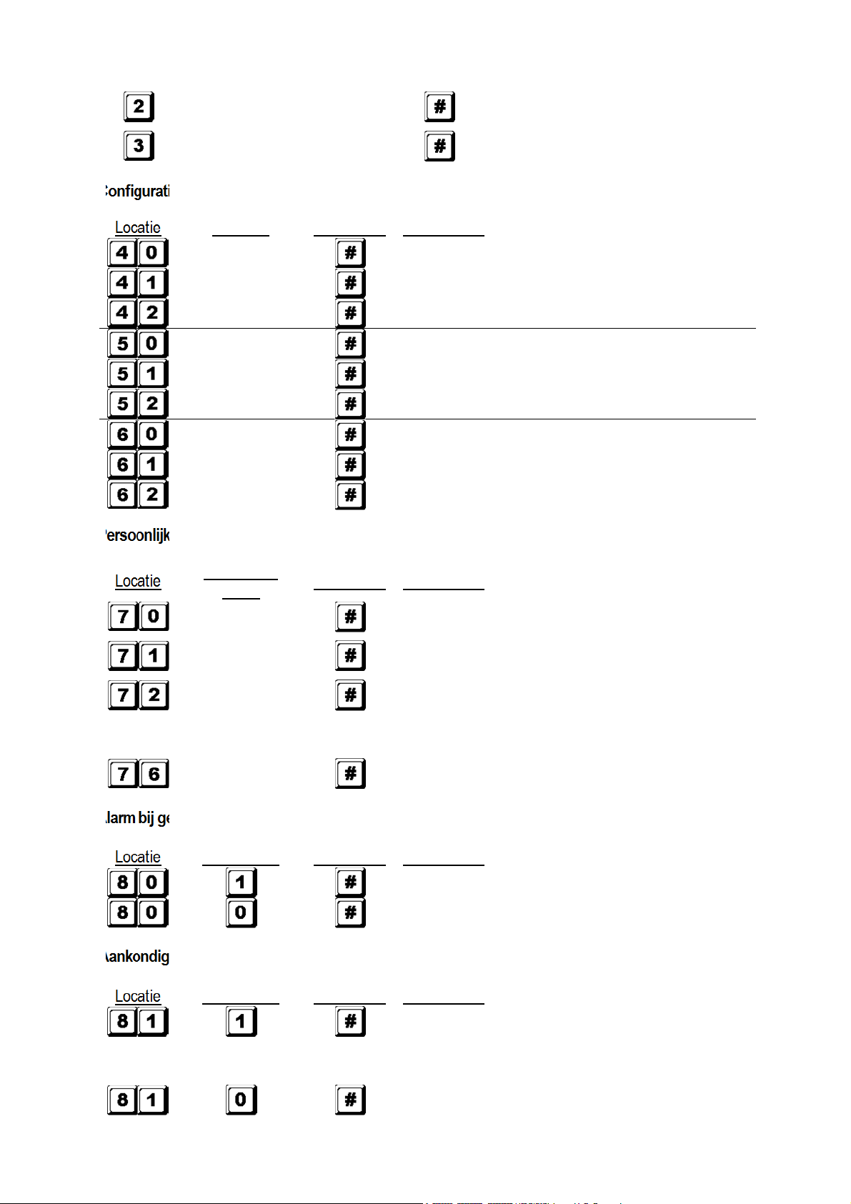
D) Configuratie van de uitgangsmodi – Installatieprogrammering
1 tot 999s
Uitgang 1 momentmodus van 1 tot 999 seconden
Uitgang 1 in start-stopmodus (schakeling)
Uitgang 1 in start-stopmodus met verkorte code
1 tot 999s
Uitgang 2 momentmodus van 1 tot 999 seconden
Uitgang 2 in start-stopmodus (schakeling)
Uitgang 2 in start-stopmodus met verkorte code
1 tot 999s
Uitgang 3 momentmodus van 1 tot 999 seconden
Uitgang 3 in start-stopmodus (schakeling)
Uitgang 3 in start-stopmodus met verkorte code
E) Persoonlijke veiligheid – Installatieprogrammering
uitgang 2
uitgang 3
Locatie
codes
Bevestiging Commentaar
toetsenbord vergrendeld gedurende 30 seconden
uitgang naar de aarding
gedurende 15 minuten vergrendeld. Het toetsenbord
kan gedurende deze tijd enkel met de meestercode
worden ontgrendeld.
Alle bovenvermelde instellingen verdwijnen
F) Alarm bij geforceerde deur – Installatieprogrammering
Inschakeling alarm bij geforceerde deur
Uitschakeling alarm bij geforceerde deur
G) Aankondiging geactiveerde uitgang – Installatieprogrammering
v2 15/11/2013 VELLEMAN
geopend en het uitgangsrelais is geactiveerd met een
gebruikerscode of de egress-knop. Ideaal voor een
geruisloos slot zoals een magnetisch slot.
pieptonen bij juiste invoer.
Page 24

HAA85BL
24
Locatie
Functiecode
Bevestiging
Commentaar
Locatie
Functiecode
Bevestiging
Commentaar
Locatie
Functiecode
Bevestiging
Commentaar
0
Tijdsinstelling van 1
tot
999 second
en alvorens het
Bevestiging
Commentaar
H) Invoermodus van de gebruikerscode (auto of manueel) – Installatieprogrammering
ingedrukt te worden. De gebruikerscode MOET
evenveel digits bevatten als de meestercode (4 tot 8
digits).
Manuele code-invoer. moet na de invoer ingedrukt
Automatische code-invoer. hoeft na de invoer niet
worden. De gebruikerscodes kunnen 4 tot 8 digits lang
zijn maar hoeven niet evenveel digits te bevatten als
de meestercode.
OPMERKING: In single gebruikersmodus moeten zowel de gebruikerscode als de meestercode 4 digits
bevatten, ongeacht de invoermodus (auto of manueel).
I) Geluidssignalen – Installatieprogrammering
Geluidssignalen geactiveerd.
Alle geluidssignalen uitgeschakeld.
J) Tijdsinstelling van het alarm bij open deur – Installatieprogrammering
Geen alarm
1 tot 999
alarm bij open deur weerklinkt.
K) De programmeermodus verlaten
Verlaat de programmeermodus en keer terug naar de normale werkmodus.
7. Selecteren van de single of multi-usermodus
Uw HAA85BL werd ingesteld op single gebruikersmodus met als meestercode.
Single gebruikersmodus (code: 8900)
Elke uitgang kan slechts door één gebruikerscode bediend worden. De gebruikerscode moet 4 digits bevatten. Er
zijn zo’n 10 000 mogelijke combinaties. De code wordt direct in de locaties 1, 2 en 3 voor de respectievelijke 3
uitgangen geprogrammeerd. Zie “6. C) 1. Single user – Cijfers mogen herhaald worden” voor meer details.
Deze modus wordt standaard met automatische code-invoer geconfigureerd. Toets enkel de 4-cijferige code in,
hoeft niet ingedrukt te worden.
OPMERKING: Stel de manuele code-invoer in door programmeeroptie 0 op locatie 82 te kiezen indien gewenst.
Multi-user gebruikersmodus (code: 8901)
Uitgang 1 wordt door 100 individuele codes bediend terwijl uitgang 2 en 3 elk door 10 individuele codes bediend
kunnen worden. De gebruikerscode is 4 tot 8 digits lang. Er zijn zo’n 100 miljoen mogelijke combinaties. Kies voor
v2 15/11/2013 VELLEMAN
Page 25

HAA85BL
25
Default
Comment
aar Default
Comment
aar
401 Uitgang
1 in
momentmodus van 1
811 Pieptoon u
itgang
srelais
ingeschakeld
501 Uitgang
2
in momentmodus van 1
820 Manuele invoer gebruikerscode
* (multi
-
601 Uitgang
3
in momentmodus van 1
821 Manuele invoer gebruikerscode
* (single
70 Blokkering van 30 seconden na invoer
831 Geluidssignalen ingeschakeld
800 Alarm bij geforceerde deur
90 Geen alarm bij open deur
Single
gebruikersmodus ingeschakeld.
Wacht
2-3
Multi
-
user
gebruikersmodus ingeschakeld. Wacht 2
-
3
de automatische of de manuele code-invoer via de programmeeropties op locatie 82. De manuele code-invoer is
de standaardmodus. moet na de invoer ingedrukt worden. De meestercode en de gebruikerscode moeten
beiden hetzelfde aantal digits bevatten wanneer het toetsenbord in automatische code-invoer is geprogrammeerd.
Druk niet op na het invoeren van de gebruikerscode in automatische code-invoer.
Defaultwaarden
seconde
seconde
seconde
user gebruikersmodus)
gebruikersmodus)
van 10 opeenvolgende foute codes
uitgeschakeld
OPMERKING: * Alle defaultwaarden in de multi-user en single gebruikersmodi zijn identiek uitgenomen de
invoermodus van de gebruikerscode.
Beperkingen van de code-invoer te wijten aan de duress-code
Het systeem heeft een duress-functie voor code 1 in single gebruikersmodus en alle gebruikerscodes voor groep
1 in multi-usermodus. De duress-code wordt automatisch door het systeem geconfigureerd: gebruikerscode +2 of
-2. Om te vermijden dat andere codes de duress-code overlappen, is een andere gebruikerscode met als eerste
cijfer het eerste cijfer van de opgeslagen gebruikerscode +2 of -2 niet toegelaten.
Voorbeeld: Gebruikerscode 56789 werd opgeslagen. Gebruikerscodes 36789 en 76789 mogen dus niet gebruikt
worden.
Selecteren van de single gebruikersmodus
U kunt de single gebruikersmodus instellen met code 8900. Het toetsenbord blijft in deze modus tot u het systeem
vernieuwt. Zorg er wel voor dat de meestercode 4 digits lang is.
MEESTER
CODE
Selecteren van de multi-user gebruikersmodus
U kunt de multi-user gebruikersmodus instellen met code 8901. Het toetsenbord blijft in deze modus tot u het
systeem vernieuwt.
MEESTER
CODE
Het systeem vernieuwen
Bij het selecteren van een nieuwe gebruikersmodus (zie hierboven) zal het systeem alle waarden wissen met
uitzondering van de meestercode.
v2 15/11/2013 VELLEMAN
seconden na het indrukken van tot u een
bevestigende pieptoon hoort.
seconden na het indrukken van tot u een
bevestigende pieptoon hoort.
Page 26

HAA85BL
26
…
3289
opgeslagen als nieuwe persoonlijke meestercode en
8321
opgeslagen als gebruikerscode
1
met duress
-
functie voor
OPMERKING: Zorg ervoor dat, wanneer u in single gebruikersmodus bent, zowel de meestercode en de
gebruikerscode 4 digits lang zijn.
8. Het toetsenbord programmeren en gebruiken – Voorbeeld
A) Procedures
De programmering van uw HAA85BL gebeurt volledig vanaf het toetsenbord. Alle geprogrammeerde
a.
waarden worden in het niet-vluchtige geheugen opgeslagen.
Plaats het toetsenbord eerst in de programmeermodus met behulp van de meestercode en druk op om
b.
te bevestigen.
OPMERKING: Gebruik de DAP jumper en plaats het toetsenbord in de programmeermodus mocht de
meestercode vergeten zijn. Zie 4. Mastercode resetten.
c.
Ga naar de locatie en programmeer de opties. Zie “6. Programmeren van het toetsenbord – Hoofdtabel”.
d. Programmeer alle opties. Herhaal indien fout ingegeven.
LOCATIE 1 OPTIE
LOCATIE n OPTIE n
e.
Verlaat de programmeermodus met . Alle ingevoerde waarden worden opgeslagen.
B) Single gebruikersmodus – Voorbeeld
Vereisten
1.
Single gebruikersmodus
a.
b. Wijziging van de default meestercode 0000 naar een persoonlijke meestercode 3289
Stel gebruikerscode 1 op 8321
c.
d. Stel gebruikerscode 2 op 6854
e.
Stel gebruikerscode 3 op 9270
f.
Stel uitgang 1 in momentmodus, 1 seconde
g.
Stel uitgang 2 in start-stopmodus
h.
Stel uitgang 3 op start-stopmodus
Stel het toetsenbord in om, na 10 foute codes, gedurende 15 minuten te blokkeren
i.
2.
Programmeren – Ingeven van de gegevens hierboven in het toetsenbord
Programmeermodus met default meestercode
v2 15/11/2013 VELLEMAN
Single gebruikersmodus*
supergebruikerscode
uitgang 1
6854 opgeslagen als gebruikerscode 2 voor uitgang 2
9270 opgeslagen als gebruikerscode 3 voor uitgang 3
Uitgang 1 ingesteld als momentmodus, 1 seconde
Page 27

HAA85BL
27
Toetsenbord ingesteld om, na
10 foute codes,
gedurende 15
Verlaten van de programmeermodus
. All
e data hierboven werd
De d
uress
-
uitgang wordt geactiveerd
(
uitgang schakelt naar
(-)
Uitgang 2 ingesteld in start-stopmodus
Uitgang 3 ingesteld in start-stopmodus
minuten te blokkeren
opgeslagen en klaar voor gebruik
OPMERKING: * U hoeft de code 8900 niet in te geven indien het toetsenbord zich al in de single
gebruikersmodus bevindt.
Wis een verkeerde invoer met of wacht 10 seconden en robeer opnieuw.
3. Het toetsenbord gebruiken – De ingegeven data hierboven en andere default functies worden als
voorbeeld genomen
a. Om een uitgang aan te sturen, geeft u enkel de gebruikerscode in. U hoeft niet op te drukken.
Uitgang 1 wordt geactiveerd voor 1 seconde
Uitgang 2 start of stopt
Uitgang 3 start of stopt
b. De persoonlijke meestercode is een supergebruikerscode waarmee u de uitgangen kunt aansturen. Dit
laat toe met één enkele code verscheidene toetsenborden te bedienen die eenzelfde meestercode en
verschillende gebruikerscodes gebruiken. Geef de persoonlijke meestercode in en bevestig met en
het overeenkomende relaisnummer.
Uitgang 1 wordt geactiveerd voor 1 seconde
Uitgang 2 start of stopt
Uitgang 3 start of stopt
c. De duress-code hoeft niet geprogrammeerd te worden. Het toetsenbord bepaalt automatisch de duress-
code door het eerste cijfer van de gebruikerscode met 2 eenheden te verhogen.
Voorbeeld: Is gebruikerscode 1 code 1234, dan wordt de duress-code 3234. Is de gebruikerscode 1
code 8321, dan wordt gebruikerscode 0321.
Om de duress-functie te bedienen, geef de duress-code in.
aarding) en uitgang 1 wordt geactiveerd voor 1 seconde
OPMERKING: De duress-code heeft 2 functies: enerzijds activeert hij de duress-uitgang en anderzijds
activeert hij uitgang 1. De duress-code kan altijd uitgang 1 (de)activeren (in startstopmodus) maar kan de duress-uitgang niet deactiveren (terugstellen).
De verkorte code bestaat uit de eerste 2 digits van de gebruikerscode. Werd uitgang 1
d.
geprogrammeerd in start-stopmodus met verkorte code op locatie 42, dan is het mogelijk om uitgang 1
te activeren met enkel de eerste 2 digits van de gebruikerscode. Om te deactiveren moet u wel de
gehele code intoetsen.
Voorbeeld: Uitgang 1 werd opnieuw geprogrammeerd in start-stopmodus met verkorte code (locatie 42).
Complete code: 8321, verkorte code: 83.
v2 15/11/2013 VELLEMAN
Page 28

28
3289
opgeslagen als nieuwe persoonlijke
8321
opgeslagen als gebruikerscode 1 in
groep 1
11223
opgeslagen als gebruikerscode 2 in groep 1
33221
opgeslagen als gebruikerscode 3 in groep 1
Toetsenbord ingesteld om, na
10 foute codes,
Geef opzettelijk enkele foute codes in om het systeem te testen. De HAA85BL beschouwt 4 digits als
e.
één enkele code en genereert 5 pieptonen voor elke foute code-invoer. Het toetsenbord blokkeert
zichzelf gedurende 15 minuten na 10 foute codes. Het toetsenbord kan tijdens deze periode worden
teruggesteld met de meestercode.
C) Multi-user gebruikersmodus – Voorbeeld
Vereisten
1.
a.
Multi-user gebruikersmodus
b. Wijziging van de default meestercode 0000 naar een persoonlijke meestercode 3289
Stel gebruikerscode 1 in groep 1 op 8321
c.
d.
Stel gebruikerscode 2 in groep 1 op 11223
e.
Stel gebruikerscode 3 in groep 1 op 33221
f. Stel gebruikerscode 1 in groep 2 op 6854
Stel gebruikerscode 2 in groep 2 op 54321
g.
h. Stel gebruikerscode 1 in groep 3 op 9270
i.
Stel uitgang 1 in momentmodus, 1 seconde
Stel uitgang 2 in start-stopmodus
j.
k. Stel uitgang 3 in start-stopmodus
l.
Stel het toetsenbord in om, na 10 foute codes, gedurende 15 minuten te blokkeren
2.
Programmeren – Ingeven van de gegevens hierboven in het toetsenbord
HAA85BL
Uitgang 1 start
Uitgang 2 stopt
Toetsenbord is vrijgemaakt en hervat normale werking
Programmeermodus met default meestercode
Multi-user gebruikersmodus*
meestercode en supergebruikerscode
met duress-functie
met duress-functie
met duress-functie
6854 opgeslagen als gebruikerscode 1 in groep 2
54321 opgeslagen als gebruikerscode 2 in groep 2
9270 opgeslagen als gebruikerscode 1 in groep 3
Uitgang 1 ingesteld als momentmodus, 1 seconde
Uitgang 2 ingesteld in start-stopmodus
Uitgang 3 ingesteld in start-stopmodus
gedurende 15 minuten te blokkeren
v2 15/11/2013 VELLEMAN
Page 29

HAA85BL
29
Verlaten van de programmeermodus. Alle data
Voorbeeld
: Gebruikerscodes
in gro
e
p 1 Overeenstemmende
duress
-
codes
8321
0321
11223
31223
33221
53221
De duress
-
uitgang wordt geactiveerd (uitgang schakelt naar
hierboven werd opgeslagen en klaar voor gebruik
OPMERKING: * U hoeft de code 8901 niet in te geven indien het toetsenbord zich al in de single
gebruikersmodus bevindt.
Wis een verkeerde invoer met of wacht 10 seconden en robeer opnieuw.
Het toetsenbord gebruiken – De ingegeven data hierboven en andere default functies worden als
3.
voorbeeld genomen
a.
Om uitgang 1 aan te sturen, geeft u enkel de gebruikerscodes in groep 1 in. Bevestig met .
Uitgang 1 wordt geactiveerd voor 1 seconde
Uitgang 1 wordt geactiveerd voor 1 seconde
Uitgang 1 wordt geactiveerd voor 1 seconde
Om uitgang 2 aan te sturen, geeft u enkel de gebruikerscodes in groep 2 in. Bevestig met .
b.
Uitgang 2 start of stopt
Uitgang 2 start of stopt
Om uitgang 3 aan te sturen, geeft u enkel de gebruikerscodes in groep 3 in. Bevestig met .
c.
Uitgang 3 start of stopt
De persoonlijke meestercode is een supergebruikerscode waarmee u de uitgangen kunt aansturen. Dit
d.
laat toe met één enkele code verscheidene toetsenborden te bedienen die eenzelfde meestercode en
verschillende gebruikerscodes gebruiken. Geef de persoonlijke meestercode in en bevestig met en
het overeenkomende relaisnummer.
Uitgang 1 wordt geactiveerd voor 1 seconde
Uitgang 2 start of stopt
Uitgang 3 start of stopt
De duress-code hoeft niet geprogrammeerd te worden. Het toetsenbord bepaalt automatisch de duress-
e.
code door het eerste cijfer van gebruikerscode 1 met 2 eenheden te verhogen. Alle gebruikerscodes
hebben de duress-functie.
Om de duress-functie te bedienen, geef de duress-code(s) in.
v2 15/11/2013 VELLEMAN
aarding) en uitgang 1 wordt geactiveerd voor 1 seconde
Page 30

HAA85BL
30
De duress
-
uitgang wordt geactiveerd (uitgang schakelt naar
De
duress
-
uitgang wordt geactiveerd (uitgang schakelt naar
aarding) en uitgang 1 wordt geactiveerd voor 1 seconde
aarding) en uitgang 1 wordt geactiveerd voor 1 seconde
OPMERKING: De duress-code heeft 2 functies: enerzijds activeert hij de duress-uitgang en anderzijds
activeert hij uitgang 1. De duress-code kan altijd uitgang 1 (de)activeren (in startstopmodus) maar kan de duress-uitgang niet deactiveren (terugstellen). Enkel de
gebruikerscodes in groep 1 kunnen de duress-uitgang (deactiveren (terugstellen).
De verkorte code bestaat uit de eerste 2 digits van de gebruikerscode(s). Werd de uitgang
f.
geprogrammeerd in start-stopmodus met verkorte code (programmeeroptie 42 voor de gebruikerscodes
in groep 1 en programmeeroptie 52 voor de gebruikerscodes in groep 2), dan is het mogelijk om de
uitgang te activeren met enkel de eerste 2 digits van de gebruikerscode(s). Om te deactiveren moet u
wel de gehele code(s) intoetsen.
Voorbeeld: Uitgang 1 werd opnieuw geprogrammeerd in start-stopmodus met verkorte code (locatie 42).
Complete code gebruikerscode 1 in groep 1: 8321, verkorte code: 83.
gebruikerscode 2 in groep 1: 11223, verkorte code: 11.
Uitgang 1 start
Uitgang 1 stopt
Uitgang 1 start
Uitgang 1 stopt
g.
Geef opzettelijk enkele foute codes in om het systeem te testen. De HAA85BL beschouwt 4 digits als
één enkele code en genereert 5 pieptonen voor elke foute code-invoer. Het toetsenbord blokkeert
zichzelf gedurende 15 minuten na 10 foute codes. Het toetsenbord kan tijdens deze periode worden
teruggesteld met de meestercode.
Toetsenbord is vrijgemaakt en hervat normale werking
D) Een gebruiker verwijderen in multi-user gebruikersmodus
Wenst u een gebruiker de toegang te weigeren, ga dan als volgt te werk:
Stel het toetsenbord in programmeermodus met de persoonlijke meestercode en .
1.
Toetsenbord staat in programmeermodus
Geef het nummer van de gebruiker (00~99 voor uitgang 1; 0~9 voor uitgangen 2 en 3) en druk op om
2.
een gebruikerscode te wissen.
Om gebruiker 05 in groep 1 te verwijderen, druk
Om gebruiker 3 in groep 2 te verwijderen, druk
Om gebruiker 2 in groep 3 te verwijderen, druk
3. Wis verdere gewenste codes.
4. Verlaat de programmeermodus door op te drukken.
v2 15/11/2013 VELLEMAN
Page 31

HAA85BL
31
7. Technische specificaties
• Werkspanning
12V-24V AC/DC, geen jumper nodig voor selectie van de spanning
• Gebruikersmodi
Single gebruikersmodus, auto of manuele code-invoer
a)
b) Multi-user gebruikersmodus: 100 gebruikerscodes voor uitgang 1 (gebruiker 00-99), auto of manuele code-
invoer
10 gebruikerscodes voor uitgang 2 (gebruiker 0-9), auto of manuele codeinvoer
10 gebruikerscodes voor uitgang 3 (gebruiker 0-9), auto of manuele codeinvoer
• Mogelijke combinaties gebruikerscode
a)
Single gebruikersmodus: 10 000
b) Multi-user gebruikersmodus: 111 110 000
• Sensorterminals
a)
Egress-ingang: N.O. aangesloten op de (-) aarding
Ingang deursensor: N.C. aangesloten op de (-) aarding
b)
c)
Uitschakeling relais 1: N.O. aangesloten op de (-) aarding
• Contacten relaisuitgang
UITGANG 1: N.C. en N.O. droge contacten, 5A / 30VDC max.
UITGANG 2: N.C. en N.O. droge contacten, 1A / 30VDC max.
UITGANG 3: NPN open collector, 100mA sink / 24VDC max.
• Contact sabotageschakelaar
N.C. droog contact, 50mA max.
• Waarden duress-uitgang, sassysteem en geactiveerde toets
NPN open collector schakelt naar aarding wanneer actief, 24DC / 100mA sink
• Toegelaten invoertijd
Max. invoertijd per digit: 10 seconden
a)
b) Max. invoertijd voor gehele code: 30 seconden
• Afmetingen
117 x 74 x 48mm
• Gewicht
180g
8. Toepassingsvoorbeelden
1. Basisbedrading van een stand-alone deurslot met toelatingscode en aanduiding (zie fig. 2)
• Verbind de 1N4004 zo dicht mogelijk bij het deurslot en parallel aan de voedingsterminal van het slot zodat
de geïnduceerde spanning geabsorbeerd en het toetsenbord niet beschadigd wordt. De 1N4004 is niet
verplicht indien het elektrische slot door een AC-spanning wordt gevoed.
• Om elektrostatische schokken te voorkomen, moet de (-) terminal van het toetsenbord altijd aarden.
v2 15/11/2013 VELLEMAN
Page 32

HAA85BL
32
• De groene led licht op terwijl het toetsenbord het elektrische slot opent.
• Aansluiting “output 3” naar “output 1 disable” is optioneel. Met deze aansluiting gebruikt u uitgang 3 als een
toelating. U kunt dus gebruikercode 3 ingegeven zodat het slot uitgeschakeld en de toegang ontzegd
wordt. Stel uitgang 3 in start-stopmodus (programmeeroptie 61) voor on-offaansturing. De rode led licht op
wanneer u het slot uitschakelt.
• Isoleer alle niet-gebruikte kabels om kortsluiting te vermijden.
OPGELET: Om veiligheidsredenen wordt de toegangscode best enkel bewaard door de eigenaar van het
gebouw. Zorg er eerst voor dat iedereen het gebouw heeft verlaten alvorens deze functie in te
schakelen.
Basisbedrading van een in-en-uitschakelsysteem en een stand-alone deurslot (zie fig. 3)
2.
• Deze toepassing is identiek aan de vorige uitgenomen de led-aanduidingen. Gebruik de groene en de rode
leds als statusverklikkers zoals exit, alarm ingeschakeld, enz.
• Relaisuitgang 2 wordt gebruikt voor het aansturen van de in- en uitschakeling. Raadpleeg de handleiding
van het besturingspaneel van het alarmsysteem.
• Verbind de antisabotageschakelaar met de N.C. 24-uur noodschakeling en de duress-uitgang met de N.O.
24-uur noodschakeling.
• Aansluiting “output 3” naar “output 1 disable” is optioneel. Met deze aansluiting gebruikt u uitgang 3 als een
toelating. U kunt dus gebruikercode 3 ingegeven zodat het slot uitgeschakeld en de toegang ontzegd
wordt. Stel uitgang 3 in start-stopmodus (programmeeroptie 61) voor on-offaansturing. De rode led licht op
wanneer u het slot uitschakelt.
• De groen gele kabel is de gemeenschappelijke aarding en dient om de HAA85BL met het toetsenbord van
het alarmsysteem te verbinden.
Basisbedrading van een sassysteem met twee toetsenborden (zie fig. 4)
3.
Een sassysteem vereist 2 deuren met elk een controller. Dit voorbeeld gebruikt 2 x HAA85BL’s met een
enkelvoudige gekruiste aansluiting tussen de terminals “output 1 disable” en “interlock control output” van
beide toetsenborden. Verbind de (-) aardingsterminals van beide toetsenborden als gemeenschappelijke
aarding zodat beide toetsenborden als een sassysteem gaan functioneren. De aansluiting van de groene led
is optioneel en licht op wanneer het slot inschakelt.
• Gebruik het toetsenbord om de deur van buitenaf te openen.
• Druk op de egress-knop om de deur van binnenuit te openen.
• Verbind de magnetische sensors op deur 1 en 2.
• Zolang deur 1 geopend is, zal deur 2 gesloten blijven en omgekeerd.
• Gebruik de N.O. relaisuitgang voor een slot in arbeidsstroom en de N.C. uitgang voor een slot in
ruststroom.
• Relaisuitgang 2 is onafhankelijk en staat buiten het circuit van het sassysteem. Gebruik deze uitgang voor
ander toepassingen.
Basisbedrading van een sassysteem met 1 toetsenbord en een voeding voor controller (zie fig. 5)
4.
Deze toepassing gebruikt slechts één HAA85BL en een voeding voor controller. De voeding levert stroom aan
het hele circuit, inclusief beide elektrische sloten en het toetsenbord. Zorg ervoor dat het totale verbruik van
het circuit de max. waarden van de voeding niet overschrijdt, vooral wanneer u sloten in ruststroom gebruikt.
Verbind de terminals “interlock control output” en “output 1 disable” tussen toetsenbord en controller met
behulp van een gekruiste aansluiting. Stel een voedingspad op met een gemeenschappelijke aarding tussen
toetsenbord en voeding.
v2 15/11/2013 VELLEMAN
Page 33

HAA85BL
33
• Gebruik het toetsenbord om deur 1 van buitenaf te openen.
• Open deur 2 met de egress-knop A van buitenaf terwijl deur 1 gesloten is.
• Open deur 1 van binnenuit met de egress-knop en open deur 2 met egress-knop 2.
• Verbind de magnetische sensors op deur 1 en 2.
• Zolang deur 1 geopend is, zal deur 2 gesloten blijven en omgekeerd.
• Gebruik de N.O. relaisuitgang voor een slot in arbeidsstroom en de N.C. uitgang voor een slot in
ruststroom.
• Relaisuitgang 2 is onafhankelijk en staat buiten het circuit van het sassysteem. Gebruik deze uitgang voor
ander toepassingen.
9. Toepassingsvoorbeelden voor bijgebouwen
Tamper N.C. (zie fig. 6)
(A)
Deze schakeling is normaal gesloten zolang het toetsenbord aan de schakeldoos verbonden is. Om sabotage
te voorkomen, verbind deze terminal in serie met de N.C. 24-uur noodschakeling van uw alarmsysteem.
Deursensor (zie fig. 7)
(B)
Met behulp van een N.C. deursensor (doorgaans een magnetische deurschakelaar) kunt u volgende functies
uitvoeren: automatische deurvergrendeling, alarm bij geforceerde deur, alarm bij open deur en sassysteem
(zie “2. Aansluitingen”).
(C)
Toetsenbord actief – Roze kabel (zie fig. 8)
De uitgang schakelt gedurende 10 seconden naar de (-) wanneer een toets wordt ingedrukt. Gebruik deze
uitgang om een verklikker of zoemer aan te sturen en zo een nachtwaker te verwittigen, om een relais in te
schakelen en zo de verlichting of een CCTV-camera inschakelt…
• Isoleer het relais dat de verlichting inschakelt (laag- en hoogspanning) om beschadiging aan het
toetsenbord te voorkomen.
• Gebruik enkel één optie. Zorg ervoor dat de positieve stroom de maximale waarden van 100mA niet
overschrijdt.
• Een externe voeding en een isolatierelais zijn nodig voor het aansturen van hoogspanningspunten zoals
verlichting.
Duress-uitgang – Wit/oranje draad (zie fig. 9)
(D)
De duress-uitgang schakelt naar de (-) aarding wanneer de duress-code wordt ingegeven. Gebruik deze
uitgang om een led-verklikkertje of een zoemer aan te sturen. Verbind met de N.C. 24-uur noodschakeling van
het alarmsysteem.
• Gebruik enkel één optie. Zorg ervoor dat de positieve stroom de maximale waarden van 100mA niet
overschrijdt.
(E) Uitgang 2
1.
Aftakking van een N.C.-circuit (wit/bruine en blauwe kabels) (zie fig. 10)
• Gebruik een N.O. uitgangscontact om een N.C.-circuit van een alarmsysteem af te takken.
• Stel het uitgangscontact in start-stopmodus (programmeeroptie 51).
v2 15/11/2013 VELLEMAN
Page 34

HAA85BL
34
2. Sturing van de in- en uitschakeling van een alarmsysteem (wit/bruine en blauwe of purperen kabels)
(zie fig. 11)
• Gebruik het N.O. of het N.C. uitgangscontact om het alarmsysteem in in-uitschakelmodus in te stellen.
• Raadpleeg de handleiding van het besturingspaneel van het alarmsysteem.
• Stel uitgang 2 in momentmodus (programmeeroptie 501) voor circuits met diverse stations en start-
stopmodus (programmeeroptie 51) voor circuits met een enkel station.
Uitgang 3 (wit/rode kabel) (zie fig. 12)
(F)
Uitgang 3 is een opencollectoruitgang voor bijkomende functies en kan gebruikt worden om bijvoorbeeld een
toetsenbord in of uit te schakelen.
Voor meer informatie omtrent dit product, zie www.velleman.eu.
De informatie in deze handleiding kan te allen tijde worden gewijzigd zonder voorafgaande kennisgeving.
v2 15/11/2013 VELLEMAN
Page 35

HAA85BL
35
MODE D’EMPLOI
1. Introduction et caractéristiques
Aux résidents de l'Union européenne
Des informations environnementales importantes concernant ce produit
Ce symbole sur l'appareil ou l'emballage indique que l’élimination d’un appareil en fin de vie peut polluer
l'environnement.
Ne pas jeter un appareil électrique ou électronique (et des piles éventuelles) parmi les déchets municipaux
non sujets au tri sélectif ; une déchèterie traitera l’appareil en question.
Renvoyer les équipements usagés à votre fournisseur ou à un service de recyclage local.
Il convient de respecter la réglementation locale relative à la protection de l’environnement.
En cas de questions, contacter les autorités locales pour élimination.
Nous vous remercions de votre achat ! Lire la présente notice attentivement avant la mise en service de l’appareil. Si
l’appareil a été endommagé pendant le transport, ne pas l’installer et consulter votre revendeur.
Le HAA85BL est un digicode autonome
résidentiel à un prix abordable. Ce digicode est compatible avec quasiment n’importe quel système de verrouillage
électronique et s’utilise comme dispositif de contrôle de systèmes de sécurité et machines. Le HAA85BL accepte
plus de 100 millions de code d’utilisateurs (en mode multiutilisateur). Les données programmées seront mémorisées
dans une mémoire non volatile. Uniquement pour usage à l’intérieur.
Clavier rétro-éclairé : faible en veille, intense pendant 10 secondes après pression d'une touche.
2. Connexions (voir ill. 1)
LES VOYANTS À DEL
• ROUGE & VERT
Les voyants à DEL rouge et vert seront connectés à la guise de l’utilisateur.
• AUX ROUGE / VERT
Le voyant à DEL vert se comporte comme un indicateur d’état lors du service normal. Le voyant à DEL passe au
rouge fixe pendant que le voyant à DEL rouge est activé.
LE BORNIER
• OUTPUT 1
Contact de relais sec 5A pour gâche de porte. Des sorties N.O. (normalement ouvert) et N.C. (normalement
fermé) sont disponibles. Utiliser des sorties N.O. pour un dispositif de verrouillage de type « fail-secure » (par
rupture) et N.C. pour un dispositif de verrouillage de type « fail-safe » (à sécurité positive). Le relais peut être
programmé soit en mode marche/arrêt (commutation), soit en mode minuté de 1 à 999 secondes.
• EG IN (ENTRÉE « EGRESS » ou la sortie déportée)
Raccorder un contact d’entrée N.O. à la masse (-) à l’aide d’un bouton N.O. afin de désactiver la sortie 1. Le
bouton de sortie déportée s’installe généralement à l’intérieur à côté de la porte. Il est possible de connecter
plusieurs boutons de sortie déportée en parallèle à la borne. Laisser le contact ouvert lorsqu’il n’est pas utilisé.
• 12V-24V AC/DC (ALIMENTATION)
Raccorder à l’alimentation 12V-24V CA/CC. La connexion (-) et la masse (câble n° 15) constituent le point de
masse commune du clavier. Un cavalier de sélection pour la tension d’entrée n’est pas nécessité. Raccorder le
point CC à la polarité (+) et (-) ; il n’y a pas de discrimination pour l’entrée CA.
v2 15/11/2013 VELLEMAN
(avec rétro-éclairage) qui assurera la sécurité d’un immeuble commercial ou
Page 36

HAA85BL
36
• DOOR SENS (ENTRÉE POUR LE CAPTEUR DE PORTE)
Raccorder un contact d’entrée N.C. à la masse (-). Avec un interrupteur de porte électromagnétique N.C., le
système captera la position de la porte et donnera les instructions suivantes :
1.
Reverrouillage automatique
Reverrouillage immédiat après l’entrée valide d’un code avant l’écoulement du délai programmé pour la sortie
1.
Alarme en cas d’effraction
2.
Le clavier produit instantanément une alarme lors de l’effraction de la porte sans code d’utilisateur valide.
L’alarme retentira pendant 60 secondes et pourra être interrompu à l’aide du code d’utilisateur 1 ou un des
codes d’utilisateur du groupe 1. Cette fonction est sélectionnable depuis les options de programmation à
l’emplacement 801.
3.
Alarme en cas de porte entrebâillée
Alarme en cas de porte entrebâillée pendant un délai supérieur au délai autorisé. Le clavier produit une
alarme après l’écoulement du délai programmé jusqu’à ce que la porte soit refermée. Le délai
d’entrebâillement est programmable de 1 à 999 secondes à l’emplacement 9.
4.
Commande d’un sas d’accès
La sortie de commande du sas d’accès commute vers (-) lors de l’ouverture d’une porte afin d’envoyer un
signal au deuxième clavier dans la connexion.
LE FAISCEAU DE CÂBLAGE
REMARQUE : Pour éviter d’endommager la partie électronique du clavier, retenir le CI et retirer une fiche avec
précaution.
• CONTACT N.C. ANTIEFFRACTION (1-2)
Contact N.C. lorsque le clavier est vissé sur le boîtier. Cet interrupteur est ouvert si le clavier est séparé du boîtier.
Raccorder la borne au circuit 24-heures d’un système d’alarme si nécessaire.
• VOYANTS À DEL VERT, ROUGE & AUX ROUGE (3-4), (5-6) & (7)
Trois voyants à DEL sur le panneau. Ils sont disponibles pour des connexions libres. Raccorder ces voyants aux
connexions de votre alarme en respectant la polarité.
Les voyants à DEL indépendants sont équipés d’une résistance limitatrice de courant de 1.5k Ω.
L’anode du voyant à DEL auxiliaire rouge est intérieurement raccordé au +5V. Il s’allume avec la cathode (câble n°
7) raccordée à la masse (-).
• SORTIE CLAVIER ACTIF OU ALARME (8)
Un transistor NPN à collecteur ouvert de max. 100mA sink et 24VCC. Le transistor sélectionne la sortie clavier
actif ou alarme via le cavalier K ou A.
Sortie clavier actif (KEY)
1.
Commute vers la masse (-) pendant 10 secondes à chaque pression d’une touche. La sortie peut être utilisée
pour l’activation d’un éclairage, de caméras CCTV ou d’un ronfleur.
Sortie alarme (AL)
2.
Commute vers la masse (-) lors de l’alarme en cas d’effraction ou en cas de porte entrebâillée. L’alarme
externe est déclenchée et avertira un emplacement éloigné.
• SORTIE 2 (9-10-11)
v2 15/11/2013 VELLEMAN
Page 37

HAA85BL
37
ÉTAT
SIGNAL SONORE
* SIGNAL DU VOYANT À DEL
1.
En mode de programmation
- - - ON
2.
Entré de touche réussie
1 bip sonore
1 flash
3.
Entrée de code réussie
2 bips sonores
2 flash
s
4.
Entrée de code erronée
5 bips sonores
5 flashs
5.
Cavalier
DAP no
n replacé
Bip sonore continu
Flashs continus
6.
En mode veille
- - -
1 flash
toutes les 2 secondes
7.
Relais de
sortie activé
Bip sonore de
1 second
e** - - -
Sortie de relais auxiliaire à contacts 1A N.O. et N.C. commandée par le code d’utilisateur 2. Conseillée pour la
commande de systèmes de sécurité. Le relais peut être programmé soit en mode marche/arrêt (commutation),
soit en mode minuté de 1 à 999 secondes.
• SORTIE 3 (12)
Un transistor NPN à collecteur ouvert conseillé pour des commandes auxiliaires. La sortie est programmée soit
en mode marche/arrêt (commutation), soit en mode minuté de 1 à 999 secondes. Commute vers la masse (-)
lorsqu’elle est activée. Valeurs max. de 100mA sink / 24VCC.
• DÉSAMORÇAGE DE LA SORTIE 1 (13)
Raccorder le contact N.O. à la masse (-). En raccordant ce contact à la masse (-), ni le code d’utilisateur 1 ni le
bouton de sortie déportée ne pourra activer la sortie 1. Utiliser ce contact dans une connexion croisée lors de
l’application d’un sas d’accès.
• SORTIE DE COMMANDE D’UN SAS D’ACCÈS (14)
Un transistor NPN à collecteur ouvert, éteint en service normal et commutant vers la masse (-) pendant les
premières 5 secondes lors de l’entrée valide d’un code d’utilisateur. La masse (-) reste activée tant que la porte
est ouverte. Utiliser cette sortie pour commander le deuxième clavier dans un sas d’accès et pour éviter que les
deux portes s’ouvrent simultanément.
• SORTIE FORCÉE (« DURESS ») (16)
Un transistor NPN à collecteur ouvert. Commute vers la masse (-) lors de l’entrée du code forcé. Utiliser la sortie
pour déclencher l’alarme ou un ronfleur afin de prévenir un gardien. Ic max. : 100mA sink ; Vc max. : 24VCC.
3. Les signaux sonores & voyants à DEL
Le ronfleur intégré et le voyant à DEL vert signalent les états suivants :
REMARQUE : * Tous les signaux sonores peuvent être (dés)activés à partir de l’emplacement 83.
** Le bip sonore d’activation peut être (dés)activé à partir de l’emplacement 82.
4. Réinitialiser le code maître
Si vous avez oublié le code maître, il est possible de le réinitialiser. Pour le code maître, n'utilisez pas une
combinaison qui est déjà affectée à un code d'utilisateur.
1. Déconnecter l’alimentation.
2. Déplacer le cavalier DAP de OFF à ON.
3. Reconnecter l’alimentation (ronfleur s’activera).
4. Remettre le cavalier DAP en position OFF (ceci fait, le ronfleur sera désactivé).
5. Le clavier se trouve en mode de programmation et sera prêt à recevoir les nouvelles données.
6. Entrer un nouveau code à 4 chiffres à l’emplacement 0 au cas où vous auriez oublié l’ancien code maître.
7. Entrer les nouvelles données, à commencer par le paragraphe B) dans le tableau sommaire ci-dessous.
v2 15/11/2013 VELLEMAN
Page 38

HAA85BL
38
Entrée de
code
Validation
Comment
aire
Ent
rée dans le mode de programmation à l’aide du code maître
Entrée de code
Validation
Commentaire
Sélection du mode simple utilisateur, effacement de toute
Sélection du mode multiutilisateur, effacement de toute donnée
Locations
Entrée de code
Validation
Commentaire
5. Le code maître d’usine – Remarque importante
Le code maître « 0000 » sera utilisé lors de la toute première programmation. Programmez toutefois un nouveau
code maître afin d’écraser l’ancien code maître et de garantir la sécurité.
6. Programmation du clavier – Tableau sommaire
A) Utilisation du code maître d’usine dans la programmation – Uniquement lors de la première
programmation
d’usine
B) Sélection du mode simple utilisateur ou multiutilisateur et rafraichissement du système –
Programmation d’installation
donnée mémorisée et rafraichissement du système
mémorisée et rafraichissement du système
C) Enregistrement du code maître personnel et des codes d’utilisateur – Programmation d’utilisation
Notes : code maître
• Programmez d'abord le code maître et ensuite les codes d'utilisateur.
• Pour programmer un nouveau code maître, n'utilisez pas une combinaison qui est déjà affectée à un
code d'utilisateur.
• Si vous avez oublié le code maître, il est possible de le réinitialiser. Voir 4. Réinitialiser le code maître.
Notes : code d'utilisateur
• Les codes d'utilisateur doivent être différents du code maître.
• Programmez un code différent pour chaque utilisateur.
1. Simple utilisateur – Chaque chiffre peut être utilisé plusieurs fois
4 chiffres fixes
4 chiffres fixes
4 chiffres fixes
4 chiffres fixes
v2 15/11/2013 VELLEMAN
Code maître personnel et supercode d’utilisateur
Code d’utilisateur 1 pour sortie 1 avec code forcé
Code d’utilisateur 2 pour sortie 2
Code d’utilisateur 3 pour sortie 3
Page 39

HAA85BL
39
Emplacement
Utilisateur
Entrée de code
Validation
Commentaire
Code maître personnel et supercode
100
codes d’utilisateur dans groupe
1
10
codes d’utilisateur dans groupe
2
10
codes d’utilisateur dans groupe
3
Emplacement
Délai
Validation
Commentaire
Emplacement
Codes erronés
Validation
Commentaire
Verrouillage du
clavier pendant
30 seconde
s après
La sortie forcée commute vers la masse après 10
Verrouillage du clavier pendant 15 minutes après 5
Emplacement
Code
Validation
Commentaire
2. Multiutilisateur – Chaque chiffre peut être utilisé plusieurs fois
4 à 8 chiffres
00 à 99 4 à 8 chiffres
0 à 9 4 à 8 chiffres
0 à 9 4 à 8 chiffres
D) Configuration des modes de sorties – Programmation d’installation
1 à 999s
Mode momentané sortie 1 de 1 à 999 secondes
Mode marche/arrêt sortie 1 (commutation)
Mode marche/arrêt sortie 1 avec code abrégé
1 à 999s
Mode momentané sortie 2 de 1 à 999 secondes
Mode marche/arrêt sortie 2 (commutation)
Mode marche/arrêt sortie 2 avec code abrégé
1 à 999s
Mode momentané sortie 3 de 1 à 999 secondes
d’utilisateur
pour sortie 1 avec code forcé
pour sortie 2
pour sortie 3
Mode marche/arrêt sortie 3 (commutation)
Mode marche/arrêt sortie 3 avec code abrégé
E) Sécurité individuelle – Programmation d’installation
5 à 10
10 tentatives d’entrée de code
tentatives d’entrée de code
à 10 tentatives d’entrée de code. Utiliser le code
maître pour déverrouiller pendant le délai de
verrouillage.
00
Configurations de sécurité ci-dessus sont effacées
F) Alarme en cas d’effraction – Programmation d’installation
Alarme armée
v2 15/11/2013 VELLEMAN
Alarme désarmée
Page 40

HAA85BL
40
Emplacement
Code
Validation
Commentaire
Bip sonore de 1 seconde
annon
çant la possibilité
Bip sonore désactivé et remplacé par
2
brefs bips
Emplacement
Code
Validation
Commentaire
Entrée automatique sélectionnée. Il n’est pas
Entrée manuelle sélectionnée
.
Il est nécessaire
Emplacement
Code
Validation
Commentaire
Emplacement
Code
Validation
Commentaire
0
Délai de
1 à 999 second
es avant le déclenchement
Validation
Comment
aire
G) Bip sonore lors de l’activation du relais – Programmation d’installation
d’ouverture de la porte lors de l’activation du relais
avec le code d’utilisateur ou le bouton de sortie
déportée. Conseillé pour des serrures
électromagnétiques insonores.
sonores lors de l’entrée valide de codes
d’utilisateur
H) Mode d’entrée du code d’utilisateur (automatique ou manuel) – Programmation d’installation
nécessaire d’enfoncer après entrée. Le code
d’utilisateur et le code maître doivent se composer
du même nombre de chiffres, c.à.d. de 4 à 8
chiffres.
d’enfoncer après entrée. Les codes d’utilisateur
peuvent se composer de 4 à 8 chiffres ; les codes
d’utilisateur et le code maître ne doivent pas
nécessairement comporter le même nombre de
chiffres.
REMARQUE : En mode simple utilisateur, tant le code maître que le code d’utilisateur doivent se composer
de 4 chiffres, quel que soit le mode d’entrée (automatique ou manuel).
I) Signaux sonores (signaux de reconnaissance) – Programmation d’installation
Signaux sonores activés
Signaux sonores désactivés
J) Délai de déclenchement de l’alarme en cas de porte entrebâillée– Programmation d’installation
Pas d’alarme en cas de porte entrebâillée
1 to 999
de l’alarme
K) Quitter le mode de programmation
Sortie du mode de programmation et retour au service normal
v2 15/11/2013 VELLEMAN
Page 41

HAA85BL
41
Défaut Commentaire
Défaut
Commentaire
401 Sortie
1
en mode momentané de
1s 811 Signal sonore
activation du relais de
501 Sortie
2
en mode momentané de 1s
820 Entrée du code d’utilisateur manuelle
*
601 Sortie
3
en mode momentané de 1s
821 Entrée du code d’utilisateur
70 Clavier
verrouillé après entrée de 10
831 Signaux sonores activés
800 Alarme en cas d’effraction désactivée
90
Pas d’alarme en cas de porte
7. Sélection du mode simple utilisateur ou multiutilisateur
Le HAA85BL est configuré d’usine en mode utilisateur simple avec code maître .
Mode utilisateur simple (code : 8900)
Chaque sortie ne peut être actionnée qu’avec un seul code d’utilisateur de 4 chiffres (10 000 combinaisons
possibles). Le code peut être programmé directement dans les emplacements 1, 2 et 3 pour les 3 sorties
respectives. Voir « 6. C) 1. Simple utilisateur – Chaque chiffre peut être utilisé plusieurs fois » pour plus de
détails. Ce mode est configuré par défaut en mode entrée de code automatique. Il suffit d’entrer le code à 4
chiffres ; il n’est pas nécessaire d’enfoncer .
REMARQUE : Configurer le clavier en mode entrée de code manuelle en programmant l’option 0 à
l’emplacement 82 si nécessaire.
Mode multiutilisateur (code : 8901)
Sortie 1 peut être actionnée par 100 codes, tandis que les sorties 2 et 3 peuvent être actionnées par 10 codes,
chaque code comportant de 4 à 8 chiffres offrant ainsi plus de 100 millions de combinaisons possibles. Les codes
d’utilisateur peuvent être configurés à partir de l’emplacement 82, l’entrée de code manuelle étant le mode par
défaut. Enfoncer après l’entrée du code. Notez que, soit le code d’utilisateur, soit le code maître, doivent
nécessairement comporter le même nombre de chiffres lorsque le claver est configuré en mode d’entrée de code
automatique. Ne pas enfoncer après l’entrée du code.
Valeurs par défaut
sortie activé
(multiutilisateur)
automatique* (utilisateur simple)
codes erronés
entrebâillée
REMARQUE : * Toutes les valeurs par défaut en modes utilisateur simple et multiutilisateur sont identiques à
l’exception du mode entrée du code d’utilisateur.
Limitations d’entrée de code en mode multiutilisateur dû au code forcé
Le clavier est équipé d’une fonction forcée pour le code d’utilisateur 1 en mode simple utilisateur et tous les codes
d’utilisateur dans le groupe 1 en mode multiutilisateur. Le code forcé est automatiquement activé en remplaçant
le premier chiffre du code d’utilisateur par un chiffre avec une valeur +2 ou -2. Pour éviter que d’autres codes ne
viennent écraser le code forcé, l’utilisation d’un code +2 ou -2 est à déconseiller.
Exemple : Code d’utilisateur 56789 mémorisé ; codes d’utilisateur 36789 et 76789 non acceptés.
Sélection du mode simple utilisateur
Sélectionner le mode simple utilisateur à l’aide du code 8900. Le clavier sera configuré dans ce mode jusqu’à ce
qu’il soit rafraichit. Veiller à composer un code maître de 4 chiffres.
CODE
v2 15/11/2013 VELLEMAN
Mode utilisateur simple activé. Patienter 2-3 secondes
Page 42

HAA85BL
42
MAÎTRE
Mode multiutilisateur activé.
Patienter 2
-
3 secondes
…
après avoir enfoncé jusqu’à ce que vous entendiez
des bips sonores.
Sélection du mode multiutilisateur
Sélectionner le mode multiutilisateur à l’aide du code 8901. Le clavier sera configuré dans ce mode jusqu’à ce
qu’il soit rafraichit.
CODE
MAÎTRE
après avoir enfoncé jusqu’à ce que vous entendiez
des bips sonores.
Rafraichissement du clavier
En choisissant un mode d’utilisation (voir ci-dessus), le clavier sera réinitialisé et toutes les données, à l’exception
du code maître, seront effacées.
REMARQUE : Veiller à ce que, soit le code d’utilisateur, soit le code maître, aient le même nombre de chiffres,
c.à.d. 4 chiffres en mode utilisateur simple.
8. Programmation et utilisation du clavier – Exemples d’utilisation
A) Procédure de programmation
Votre HAA85BL est entièrement programmé à partir du clavier frontal. Toutes les données sont
a.
sauvegardées dans une mémoire non volatile.
Instaurer d’abord le mode de programmation à l’aide du code maître et enfoncer pour valider la
b.
sélection.
REMARQUE : Utiliser le cavalier DAP pour instaurer le mode de programmation au cas où vous auriez
oublié le code maître. Voir 4. Réinitialiser le code maître.
c.
Accéder à un emplacement et programmer les options. Voir « 6. Programmation du clavier – Tableau
sommaire ».
Programmer chaque option. Répéter la programmation d’une option en cas d’entrée erronée.
d.
EMPLACEMENT 1 OPTION
EMPLACEMENT n OPTION n
e.
Quitter le mode de programmation en enfonçant . Toute donnée entrée a été sauvegardée.
B) Utilisation du clavier en mode simple utilisateur – Exemple
Conditions de paramétrage
1.
a.
Mode simple utilisateur
b. Modification du code maître par défaut 0000 en code maître personnalisé 3289
c.
Paramétrage du code d’utilisateur 1 comme 8321
Paramétrage du code d’utilisateur 2 comme 6854
d.
e. Paramétrage du code d’utilisateur 3 comme 9270
f. Paramétrage de la sortie 1 en mode momentané, 1 seconde
g. Paramétrage de la sortie 2 en mode marche/arrêt
v2 15/11/2013 VELLEMAN
Page 43

HAA85BL
43
3289
mémorisé comme nouveau code maître personnalisé et
8321
mémorisé comme code d’utilisateur 1 avec fonction forcée
Verrouillage du clavier pendant 15 minutes après 10 entrées de
Quitter la programmation. Les données sont sauvegardées et
h. Paramétrage de la sortie 3 en mode marche/arrêt
Verrouillage du clavier pendant 15 minutes après 10 entrées de code erronées
i.
2.
Programmation – Entrée dans le clavier des paramètres ci-dessus
Mode de programmation avec code maître par défaut
Mode utilisateur simple*
supercode d’utilisateur
pour sortie 1
6854 mémorisé comme code d’utilisateur 2 pour sortie 2
9270 mémorisé comme code d’utilisateur 3 pour sortie 3
Sortie 1 configurée comme mode momentané, 1 seconde
Sortie 2 configurée comme mode marche/arrêt
Sortie 3 configurée comme mode marche/arrêt
code erronées
prêtes à l’emploi
REMARQUE : * Il n’est pas nécessaire de taper le code d’utilisateur simple 8900 lorsque le clavier se
trouve en mode simple utilisateur.
Effacer une entrée erronée à l’aide de et patienter une dizaine de secondes avant de
rentrer la donnée.
3. Utilisation du clavier – Les données programmées et autres données comme référence
a. Pour commander une sortie il suffit d’entrer le code d’utilisateur. Il n’est pas nécessaire d’enfoncer .
Sortie 1 activée pendant 1 seconde
Sortie 2 est enclenchée ou déclenchée
Sortie 3 est enclenchée ou déclenchée
b. Le code maître personnalisé est un supercode d’utilisateur qui commande les sorties et qui permet de
n’utiliser qu’un seul code et de commander plusieurs claviers comportant un même code maître et
plusieurs codes d’utilisateur. Entrer un code maître personnalisé et valider avec et le numéro de la
sortie correspondante.
Sortie 1 activée pendant 1 seconde
Sortie 2 est enclenchée ou déclenchée
Sortie 3 est enclenchée ou déclenchée
c. Le code forcé ne nécessite aucune programmation puisque le clavier détermine automatiquement le
code en ajoutant 2 unités au premier chiffre du code d’utilisateur 1.
Exemple : Le code d’utilisateur étant 1234, le code forcé sera 3234. Le code d’utilisateur étant 8321, le
code forcé sera 0321.
v2 15/11/2013 VELLEMAN
Page 44

HAA85BL
44
Activation de la sortie forcée
(
sortie commute vers la masse
(-))
Mode de programmation avec code maître par
3289
mémorisé comme nouveau code maître
Pour commander la fonction forcée, entrer le code forcé.
et sortie 1 est activée pendant 1 seconde
REMARQUE : Le code forcé a une double fonction : il actionne la sortie forcée et en même temps il
actionne la sortie 1. Le code forcé peut (dés)activer (en mode marche/arrêt) la sortie 1,
mais ne pourra pas désactiver (réinitialiser) la sortie forcée.
Le code abrégé est constitué des deux premiers chiffres du code d’utilisateur. Si la sortie 1 a été
d.
programmée en mode marche/arrêt avec le code abrégé à l’emplacement 42, il sera possible
d’actionner la sortie 1 à l’aide des deux premiers chiffres du code d’utilisateur. La désactivation toutefois
nécessite l’entrée du code complet.
Exemple : Sortie 1 a été reprogrammée en mode marche/arrêt avec le code abrégé (emplacement 42).
Code complet : 8321, code abrégé : 83.
Sortie 1 est enclenchée
Sortie 2 est déclenchée
e.
Entrer quelques codes erronés afin de vérifier la fiabilité. Le HAA85BL identifiera 4 chiffres comme un
code et produira 5 bips sonores pour chaque entrée valide de code. Le clavier sera verrouillé pendant
15 minutes après 10 entrées de code erronées. Réinitialiser le clavier pendant le verrouillage à l’aide du
code maître.
Déverrouillage, le clavier reprend le service normal
C) Utilisation du clavier en mode multiutilisateur – Exemple
1.
Conditions de paramétrage
Mode multiutilisateur
a.
b.
Modification du code maître par défaut 0000 en code maître personnalisé 3289
c.
Paramétrage du 1
d. Paramétrage du 2
Paramétrage du 3
e.
f.
Paramétrage du 1
g. Paramétrage du 2
h.
Paramétrage du 1
Paramétrage de la sortie 1 en mode momentané, 1 seconde
i.
j.
Paramétrage de la sortie 2 to en mode marche/arrêt
er
code d’utilisateur dans le groupe 1 comme 8321
ème
code d’utilisateur dans le groupe 1 comme 11223
ème
code d’utilisateur dans le groupe 1 comme 33221
er
code d’utilisateur dans le groupe 2 comme 6854
ème
code d’utilisateur dans le groupe 2 comme 54321
er
code d’utilisateur dans le groupe 3 comme 9270
k. Paramétrage de la sortie 3 en mode marche/arrêt
l.
Verrouillage du clavier pendant 15 minutes après 10 entrées de code erronées
2.
Programmation – Entrée dans le clavier des paramètres ci-dessus
v2 15/11/2013 VELLEMAN
défaut
Mode multiutilisateur*
personnalisé et supercode d’utilisateur
Page 45

HAA85BL
45
8321
mémorisé
comme 1
er
code
d’utilisateur dans
11223
mémorisé comme 2
ème
code d’utilisateur
33221
mémorisé comme 3
ème
code d’utilisateur
6854
mémorisé comme 1
er
code d’utilisateur dans
54321
mémorisé comme 2
ème
code d’utilisateur
9270
mémorisé comme 1
er
code d’utilisateur dans
Sortie
1 configurée comme mode momentané, 1
Verrouillage du clavier pendant 15 minutes aprè
s
Quitter la programmation. Les données sont
groupe 1 avec fonction forcée
dans groupe 1 avec fonction forcée
dans groupe 1 avec fonction forcée
groupe 2
dans groupe 2
groupe 3
seconde
Sortie 2 configurée comme mode marche/arrêt
Sortie 3 configurée comme mode marche/arrêt
10 entrées de code erronées
sauvegardées et prêtes à l’emploi
REMARQUE : * Il n’est pas nécessaire de taper le code d’utilisateur simple 8901 lorsque le clavier se
trouve en mode simple utilisateur.
Effacer une entrée erronée à l’aide de et patienter une dizaine de secondes avant de
rentrer la donnée.
Utilisation du clavier – Les données programmées et autres données comme référence
3.
a.
Pour commander la sortie 1 il suffit d’entrer un des codes d’utilisateur du groupe 1 et de valider avec .
Sortie 1 activée pendant 1 seconde
Sortie 1 activée pendant 1 seconde
Sortie 1 activée pendant 1 seconde
Pour commander la sortie 2 il suffit d’entrer un des codes d’utilisateur du groupe 2 et de valider avec .
b.
Sortie 2 est enclenchée ou déclenchée
Sortie 2 est enclenchée ou déclenchée
c.
Pour commander la sortie 3 il suffit d’entrer un des codes d’utilisateur du groupe 3 et de valider avec .
Sortie 3 est enclenchée ou déclenchée
Le code maître personnalisé est un supercode d’utilisateur qui commande les sorties et qui permet de
d.
n’utiliser qu’un seul code et de commander plusieurs claviers comportant un même code maître et
plusieurs codes d’utilisateur. Entrer le code maître personnalisé et valider avec et le numéro de la
sortie correspondante.
v2 15/11/2013 VELLEMAN
Page 46

HAA85BL
46
Exe
mple
:
Codes
d’utilisateur dans groupe
1
Code forcé c
orrespond
ant
8321
0321
11223
31223
33221
53221
Activation de la sortie forcée (sortie commute vers la masse) et
Activation de la sortie forcée (sortie commute vers la masse) et
Activation de la sortie forcée (sortie commute vers la masse) et
Sortie 1 activée pendant 1 seconde
Sortie 2 est enclenchée ou déclenchée
Sortie 3 est enclenchée ou déclenchée
e.
Le code forcé ne nécessite aucune programmation puisque le clavier détermine automatiquement le
code en ajoutant 2 unités au premier chiffre des codes d’utilisateur du groupe 1. Tous les codes
d’utilisateur ont la fonction forcée.
Pour commander la fonction forcée, entrer le(s) code(s) forcé(s).
sortie 1 est activée pendant 1 seconde
sortie 1 est activée pendant 1 seconde
sortie 1 est activée pendant 1 seconde
REMARQUE : Le code forcé a une double fonction : il actionne la sortie forcée et en même temps il
actionne la sortie 1. Le code forcé peut (dés)activer (en mode marche/arrêt) la sortie 1,
mais ne pourra pas désactiver (réinitialiser) la sortie forcée. Les codes d’utilisateur du
groupe 1 sont les seuls codes à pouvoir désactiver (réinitialiser) la sortie forcée.
f.
Le code abrégé est constitué des deux premiers chiffres du (des) code(s) d’utilisateur. Si la sortie a été
programmée en mode marche/arrêt avec le code abrégé (option 42 pour les codes d’utilisateur du
groupe 1 et option 52 pour les codes d’utilisateur du groupe 2), il sera possible d’actionner la sortie à
l’aide des deux premiers chiffres du (des) code(s) d’utilisateur. La désactivation toutefois nécessite
l’entrée du (des) code(s) au complet.
Exemple : Sortie 1 a été reprogrammée en mode marche/arrêt avec le code abrégé (emplacement 42).
er
Code complet du 1
code d’utilisateur du groupe 1 : 8321, code abrégé : 83.
ème
2
code d’utilisateur du groupe 1 : 11223, code abrégé : 11.
Sortie 1 est enclenchée
Sortie 1 est déclenchée
Sortie 1 est enclenchée
Sortie 1 est déclenchée
Entrer quelques codes erronés afin de vérifier la fiabilité. Le HAA85BL produira 5 bips sonores pour
g.
chaque entrée valide de code. Le clavier sera verrouillé pendant 15 minutes après 10 entrées de code
erronées. Réinitialiser le clavier pendant le verrouillage à l’aide du code maître.
Déverrouillage, le clavier reprend le service normal
D) Effacement d’un utilisateur en mode multiutilisateur
v2 15/11/2013 VELLEMAN
Page 47

HAA85BL
47
Procéder comme suit pour consigner l’accès au clavier à un utilisateur :
Sélection du mode de programmation à l’aide du code maître personnalisé et .
1.
Mode de programmation
Entrer le numéro de l’utilisateur (00~99 pour la sortie 1 ; 0~9 pour les sorties 2 et 3) et enfoncer pour
2.
effacer un code d’utilisateur.
Pour effacer l’utilisateur 05 du groupe 1, enfoncer
Pour effacer l’utilisateur 3 du groupe 2, enfoncer
Pour effacer l’utilisateur 2 du groupe 3, enfoncer
3. Continuer à effacer les codes souhaités.
4.
Quitter le mode de programmation enfonçant .
7. Spécifications techniques
• Tension de service
12V-24V CA/CC, ne nécessite pas de cavalier pour la sélection de tension
• Modes d’utilisation
a)
Mode utilisateur simple, entrée de code automatique ou manuelle
b)
Mode multiutilisateur : 100 codes d’utilisateur pour sortie 1 (utilisateur 00-99), entrée de code automatique ou
manuelle
10 codes d’utilisateur pour sortie 2 (utilisateur 0-9), entrée de code automatique ou
manuelle
10 codes d’utilisateur pour sortie 3 (utilisateur 0-9), entrée de code automatique ou
manuelle
• Combinaisons de codes d’utilisateur possibles
a) Mode utilisateur simple : 10 000
Mode multiutilisateur : 111 110 000
b)
• Bornes d’entrée
a)
Entrée de la sortie déportée : N.O. raccordée à la masse (-)
b) Entrée du capteur de porte : N.C. raccordée à la masse (-)
c)
Commande d’arrêt relais 1 : N.O. raccordée à la masse (-)
• Contact relais de sortie
SORTIE 1 : contacts secs N.C. et N.O., max. 5A / 30VCC
SORTIE 2 : contacts secs N.C. et N.O., max. 1A / 30VCC
SORTIE 3 : transistor NPN à collecteur ouvert, max. 100mA sink / 24VCC
• Contact de l’interrupteur antieffraction
Contact sec N.C., max. 50mA
• Valeurs des sorties forcée, sas d’accès et clavier actif
Transistor NPN à collecteur ouvert commutant vers la masse lorsqu’activé, 24CC / 100mA sink
• Délai de rafraichissement automatique lors de l’entrée du code
v2 15/11/2013 VELLEMAN
Page 48

HAA85BL
48
a) Délai max. pour chaque chiffre : 10 secondes
Délai max. pour chaque entrée : 30 secondes
b)
• Dimensions
117 x 74 x 48mm
• Poids
180g
8. Exemples de connexions
Connexion de base d’une gâche de porte autonome avec code et indication (voir ill. 2)
1.
• Tenir la connexion entre la 1N4004 et la gâche le plus court possible et raccorder en parallèle au borne
d’alimentation afin d’absorber la tension induite et d’éviter d’endommager le clavier. La 1N4004 n’est pas
requise si la gâche reçoit une alimentation CA.
• Mettre à la terre la borne (-) du clavier pour éviter les décharges électrostatiques.
• Le voyant à DEL vert s’allume lorsque le clavier déverrouille la gâche.
• La connexion « output 3 » vers « output 1 disable » est optionnelle. Cette connexion vous permet d’utiliser la
sortie 3 comme commande d’autorisation. Entrer le code d’utilisateur 3 pour interrompre le service du clavier
après les heures de bureau et éviter l’accès non autorisé. Paramétrer sortie 3 en mode marche/arrêt (option
61) pour une commande on/off. Le voyant à DEL rouge s’allume lorsque le service de la gâche s’arrête.
• Isoler tout câble exclus du circuit pour éviter les courts-circuits.
ATTENTION : Il est préférable de ne confier le code d’autorisation qu’au propriétaire de l’immeuble pour des
raisons de sécurité. Veiller à ce que l’immeuble soit évacué avant de verrouiller l’immeuble.
2.
Connexion de base de l’alarme avec d’une gâche autonome (voir ill. 3)
• Exemple similaire à la précédente sauf pour les voyants à DEL. Les voyants à DEL vert et rouge indiquent
l’état, p.ex. sortie, armement de l’alarme, etc.
• Utiliser la sortie 2 comme commande d’armement et de désarmement de l’alarme. Consultez la notice du
clavier de votre système d’alarme.
• Raccorder l’interrupteur antieffraction au circuit 24-heures N.C. et la sortie forcée au circuit 24-heures N.O.
• La connexion « output 3 » vers « output 1 disable » est optionnelle. Cette connexion vous permet d’utiliser la
sortie 3 comme commande d’autorisation. Entrer le code d’utilisateur 3 pour interrompre le service du clavier
après les heures de bureau et éviter l’accès non autorisé. Paramétrer sortie 3 en mode marche/arrêt (option
61) pour une commande on/off. Le voyant à DEL rouge s’allume lorsque le service de la gâche s’arrête.
• Le câble jaune vert est une masse commune pour le raccordement du HAA85BL et le clavier du système
d’alarme.
3.
Connexion de base d’un sas d’accès avec 2 HAA85BLs (voir ill. 4)
Un sas d’accès nécessite un contrôleur pour chaque porte. Cet exemple utilise 2 HAA85BLs avec une
connexion croisée entre les bornes « output 1 disable » et « interlock control output » des deux claviers.
Raccorder la masse (-) des deux claviers et afin d’obtenir une masse commune. La connexion du voyant à
DEL vert est optionnelle. Elle s’allumera lorsque la gâche est activée.
• Utiliser le clavier pour ouvrir la porte de l’extérieur.
• Enfoncer le bouton de sortie déportée pour ouvrir la porte de l’intérieur.
• Raccorder les capteur électromagnétiques sur les portes 1 et 2.
• Lorsque la porte 1 est ouverte, la porte 2 sera verrouillée et vice versa.
v2 15/11/2013 VELLEMAN
Page 49

HAA85BL
49
• Utiliser la sortie de relais N.O. pour des gâches par rupture et la sortie de relais N.C. pour des gâches à
sécurité positive.
• La sortie 2 est autonome et ne fait pas partie du circuit du sas d’accès. Elle peut être utilisée pour d’autres
applications.
4.
Connexion de base d’un sas d’accès avec 1 clavier et une alimentation de contrôleur (voir ill. 5)
Cet exemple utilise un seul HAA85BL et une alimentation avec contrôleur. L’alimentation alimente l’ensemble
du circuit, les deux gâches et le claver. Veiller à ce que la consommation du circuit n’excède pas les valeurs
maximales de l’alimentation, particulièrement lorsque vous utilisez des gâches à sécurité positive.
Utiliser une connexion croisée pour raccorder les bornes « interlock control output » et « output 1 disable »
entre le clavier et le contrôleur. Établir une masse commune entre le clavier et l’alimentation afin de créer une
piste d’alimentation.
• Utiliser le clavier pour ouvrir porte 1 de l’extérieur.
• Ouvrir porte 2 à l’aide du bouton de sortie déportée A de l’extérieur lorsque porte 1 et verrouillée.
• Ouvrir porte 1 de l’intérieur à l’aide du bouton de sortie déportée et ouvrir porte 2 à l’aide du bouton de
sortie déportée 2.
• Raccorder les capteur électromagnétiques sur les portes 1 et 2.
• Lorsque la porte 1 est ouverte, la porte 2 sera verrouillée et vice versa.
• Utiliser la sortie de relais N.O. pour des gâches par rupture et la sortie de relais N.C. pour des gâches à
sécurité positive.
• La sortie 2 est autonome et ne fait pas partie du circuit du sas d’accès. Elle peut être utilisée pour d’autres
applications.
9. Exemples de connexions pour les bâtiments auxiliaires
(A)
Contact N.C. antieffraction (voir ill. 6)
Le commutateur antieffraction est normalement fermé lorsque le clavier sur le coffret électrique. Pour éviter les
effractions, raccorder la borne en série au circuit 24-heures N.C. du système d’alarme.
Capteur de porte (voir ill. 7)
(B)
À l’aide d’un capteur de porte N.C. (habituellement un interrupteur de porte électromagnétique), il est possible
d’obtenir les fonctions suivantes : reverrouillage automatique, alarme en cas d’effraction, alarme en cas de
porte entrebâillée et la commande d’un sas d’accès (voir « 2. Connexions »).
Clavier actif – Câble rose (voir ill. 8)
(C)
La sortie clavier actif commute vers la masse (-) pendant 10 secondes lorsqu’une touche est enfoncée. Utiliser
la sortie pour activer une DEL ou un ronfleur afin de prévenir un gardien de nuit, activer l’éclairage ou une
caméra CCTV…
• Isoler dûment le relais entre la basse et la haute tension pour éviter d’endommager le circuit du clavier.
• Nous conseillons de n’utiliser qu’une seule option. Veiller à ce que le courant positif ne dépasse pas la
valeur maximale de 100mA.
• Une alimentation externe et un relais d’isolation sont nécessaires pour l’alimentation d’appareils à haute
consommation comme p.ex. une ampoule.
Sortie forcée – Câble blanc/orange (voir ill. 9)
(D)
v2 15/11/2013 VELLEMAN
Page 50

HAA85BL
50
La sortie forcée commute vers la masse (-) lorsque le code forcé est formé. Utiliser la sortie pour activer une
DEL ou un ronfleur. À raccorder au circuit 24-heures N.C. d’un système d’alarme.
• Nous conseillons de n’utiliser qu’une seule option. Veiller à ce que le courant positif ne dépasse pas la
valeur maximale de 100mA.
(E)
Sortie 2
1. Dérivation d’un circuit N.C. (câbles blanc/marron et bleu) (voir ill. 10)
• Utiliser le contact de sortie N.O. pour dériver un circuit N.C. d’un système d’alarme.
• Paramétrer le contact de sortie en e marche/arrêt (option 51).
2. Armement et désarmement de l’alarme (câbles blanc/marron et bleu ou pourpre) (voir ill. 11)
• Utiliser le contact de sortie N.O. ou N.C. pour sélectionner le mode.
• Consulter la notice du clavier du système d’alarme.
• Paramétrer la sortie 2 en mode momentané (option 501) pour un système à stations multiples et en
mode marche/arrêt pour un système à une seule station.
(F) Sortie 3 (câble blanc/rouge) (voir ill. 12)
La sortie 3 est une sortie à collecteur ouvert pour des commandes auxiliaires. Utiliser cette sortie pour
l’activation ou la désactivation d’un clavier ou d’un système d’alarme, etc. Elle peut également alimenter un
relais.
Pour plus d’information concernant cet article, visitez notre site web www.velleman.eu.
Toutes les informations présentées dans cette notice peuvent être modifiées sans notification préalable.
v2 15/11/2013 VELLEMAN
Page 51

HAA85BL
51
MANUAL DEL USUARIO
1. Introducción & Características
A los ciudadanos de la Unión Europea
Importantes informaciones sobre el medio ambiente concerniente a este producto
Este símbolo en este aparato o el embalaje indica que, si tira las muestras inservibles, podrían dañar el
medio ambiente.
No tire este aparato (ni las pilas, si las hubiera) en la basura doméstica; debe ir a una empresa
especializada en reciclaje. Devuelva este aparato a su distribuidor o a la unidad de reciclaje local.
Respete las leyes locales en relación con el medio ambiente.
Si tiene dudas, contacte con las autoridades locales para residuos.
¡Gracias por haber comprado el HAA85BL! Lea atentamente las instrucciones del manual antes de usarlo. Si el
aparato ha sufrido algún daño en el transporte no lo instale y póngase en contacto con su distribuidor.
El HAA85BL es un teclado digital y autónomo (con retroiluminación) que asegura la seguridad de un edificio
comercial o residencial a precia razonable. Este teclado es compatible con casi cualquier sistema de bloqueo
electrónico y se utiliza como aparato de control en sistemas de seguridad y máquinas. El HAA85BL acepta más de
100 millones de códigos de usuarios (en el modo ‘multiusuario’). Los datos programados se guardarán en una
memoria no volátil. Sólo para uso en interiores.
Teclado con retroiluminación: débil en el modo 'stand-by', intensa durante 10 segundos después de haber pulsado
una tecla.
2. Conexiones (véase fig. 1)
LOS INDICADORES LED
• ROJO & VERDE
Conecte el indicador LED rojo y verde a su antojo.
• AUX ROJO / VERDE
El indicador LED verde es un indicador del estado durante el funcionamiento normal. El indicador LED se vuelve
al rojo fijo mientras que el indicador LED AUX rojo se activa.
LOS BORNES
• OUTPUT 1
Contacto de relé seco de 5A para conmutador de puerta. Salidas normalmente abiertas (N.A.) y normalmente
cerradas (N.C.) están disponibles. Utilice las salidas N.A. para un sistema de bloqueo del tipo « fail-secure » (si la
alimentación falla, la puerta queda con seguro) y N.C. para un sistema de bloqueo del tipo « fail-safe » (si la
alimentación falla, la puerta queda sin seguro). Es posible programar el relé, bien en el modo arranque/parada
(conmutación), bien en el modo temporizador de 1 a 999 segundos.
• EG IN (ENTRADA « EGRESS »)
Conecte un contacto de entrada N.A. con un botón N.A. a la masa (-) para desactivar la salida 1. El botón ‘egress’
suele instalarse en casa al lado de la puerta. Es posible conectar varios botones ‘egress’ en paralelo al borne.
Deje que el contacto quede abierto si no se utiliza.
• 12V-24V AC/DC (ALIMENTACIÓN)
Conecte una alimentación 12V-24V CA/CC. La conexión (-) y la masa (cable n° 15) son puntas de masa
comunes del teclado. No se necesita un jumper de selección para la tensión de entrada. Conecte la punta CC a
la polaridad (+) y (-); No hay una discriminación para la entrada CA.
v2 15/11/2013 VELLEMAN
Page 52

HAA85BL
52
• DOOR SENS (ENTRADA PARA EL SENSOR DE PUERTA)
Conecte un contacto de entrada N.C. a la masa (-). Con un conmutador electromagnético de puerta N.C., el
sistema determinará la posición de la puerta y dará las instrucciones siguientes:
Bloqueo automático
1.
El sistema bloquea automáticamente la puerta después de haber introducido un código válido antes de que se
haya transcurrido el tiempo programado para la salida 1.
2.
Alarma en caso de puerta forzada
El teclado emite inmediatamente una alarma si se fuerza la puerta sin código de usuario válido. La alarma
sonará durante 60 segundos y puede ser interrumpido con el código de usuario 1 o uno de los códigos de
usuario del grupo 1. Es posible seleccionar esta función desde las opciones de programación en el sitio 801.
Alarma en caso de puerta abierta
3.
Alarma en caso de puerta abierta durante un período superior al período autorizado. El teclado emite una
alarma después del tiempo programado hasta que se vuelva a cerrar la puerta. Es posible ajustar el tiempo de
1 a 999 segundos en la posición 9.
4.
Sistema de esclusa
Conexión a (-) si la puerta se abre para enviar una señal al segundo teclado de la conexión.
EL CABLEADO
NOTA: para evitar dañar la parte electrónica del teclado, sujeta la placa firmemente y saque el conector
cuidadosamente.
• CONTACTO N.C. ANTISABOTAJE (TAMPER) (1-2)
Contacto N.C. si el teclado está fijado a la caja. Este contacto se abre al sacar el teclado de la caja. Conecte esta
salida en serie al circuito de 24 horas de un sistema de alarma si fuera necesario.
• LEDs VERDES, ROJOS & AUX ROJOS (3-4), (5-6) & (7)
Hay tres LEDs disponibles en el panel para las conexiones libres. Conecte estos LEDs a las conexiones de su
alarma. Controle la polaridad.
Los LEDs independientes están equipados con una resistencia de 1.5k Ω para limitar la corriente.
El ánodo del LED AUX rojo se conecta de manera interna a +5V. Se ilumina con el cátodo (cable n° 7) conectado
a la masa (-).
• SALIDA TECLADO ACTIVO O SALIDA DE ALARMA (8)
Un transistor NPN con colector abierto de máx. 100mA sink y 24VCC. Es posible seleccionarlo por el jumper K o
A para la salida activa o la salida de alarma.
1.
Salida activa (KEY)
Conmuta durante 10 segundos a la masa (-) con cada presión en una tecla. Es posible utilizar la salida para
encender una luz, activar cámaras CCTV o zumbadores.
Salida alarma (AL)
2.
Conmuta a la masa (-) si la alarma se activa en caso de puerta forzada o abierta. Una alarma externa se
activará.
• SALIDA 2 (9-10-11)
v2 15/11/2013 VELLEMAN
Page 53

HAA85BL
53
ESTADO
SEÑAL SONORA*
SEÑAL DEL LED
1. En el modo de programación
- - - ON
2. Pulsar la tecla de manera correcta
1 bip sonoro
1 parpadeo
3. Introducir el código correcto
2 bips sonoros
2 parpadeos
4. Introducir el código incorrecto
5 bips sonoros
5 parpadeos
5. No ha vuelta a poner el jumper
Bip sonoro continuo
parpadeo contino
6. En el modo standby
- - -
1 parpadeo cada 2 segundos
7. Relé de salida activado
Bip sonoro de 1
segundo**
- - -
Salida de relé auxiliar con contactos de 1A N.A. y N.C. controlado por el código de usuario 2. Ideal para la
conexión de sistemas de seguridad. Es posible programar el relé, bien en el modo arranque/parada
(conmutación), bien en el modo temporizador de 1 a 999 segundos.
• SALIDA 3 (12)
Un transistor NPN con colector abierto ideal para controlar sistemas de seguridad. Es posible programar la salida,
bien en el modo arranque/parada (conmutación), bien en el modo temporizador de 1 a 999 segundos. Conmuta a
la masa (-) al activarse. Valores máx. de 100mA sink / 24VCC.
• DESACTIVACIÓN DE LA SALIDA 1 (13)
Conecte el contacto N.A. a la masa (-). Al conectar este contacto a la masa (-), ni el código de usuario 1, ni el
botón ‘egress’ puede activar la salida 1. Utilice este contacto en una conexión cruzada para la aplicación de una
esclusa.
• SALIDA PARA EL SISTEMA DE ESCLUSA (14)
Un transistor NPN con colector abierto. Está desactivado durante un funcionamiento normal y conmuta
inmediatamente a la masa (-) durante los primeros 5 segundos después de que se haya introducido un código de
usuario válido. La masa (-) queda activada mientras la puerta esté abierta. Utilice esta salida para controlar el
segundo teclado en un sistema de esclusa y para evitar que las dos puertas se abran simultáneamente.
• SALIDA «DURESS» (SALIDA FORZADA) (16)
Un transistor NPN con colector abierto. Conmuta a la masa (-) al introducir un código forzado. Utilice esta salida
para activar la alarma o un zumbador. Ic máx. : 100mA sink; Vc máx.: 24VCC.
3. Las señales sonoras & los LEDs
El zumbador incorporado y el LED verde indican los siguientes estados:
DAP
NOTA: * es posible (des)activar todas las señales sonoras al programar las opciones de posición 83.
** es posible (des)activar el bip sonoro de activación al programar las opciones de posición 82.
4. Reinicializar el código maestro
Si ha olvidado el código maestro puede reinicializarlo. Para el código maestro, no utilice una combinación que ya ha
sido utilizado para un código de usuario.
1. Desconecte la alimentación.
2. Cambie la posición del puente DAP de OFF a ON.
3. Vuelva a conectar la alimentación (el zumbador se activará).
4. Vuelva a poner el puente DAP en la posición OFF (ahora, el zumbador está desactivado).
5. El teclado está en el modo de programación y está listo para recibir los nuevos datos.
6. Introduzca un nuevo código de 4 cifras en la posición 0 si ha olvidado el antiguo código maestro.
7. Introduzca los nuevos datos, empezando con el punto B) PROGRAMAR EL TECLADO - RESUMEN.
v2 15/11/2013 VELLEMAN
Page 54

HAA85BL
54
introducir el código
Confirmación
Comentario
Entrar en el modo de programación al utilizar el código maestro
introducir el código
Confirmación
Comentario
Seleccionar el modo ‘monousuario’, borrar todos los datos
Seleccionar el modo ‘multiusuario’, borrar todos los datos
Introducir el
5. El código maestro de fábrica – Nota importante
Al programar el teclado por primera vez, utilice el código maestro « 0000 ». Después, programe un nuevo código
maestro.
6. Programar el teclado – Resumen
A) Usar el código maestro para entrar en el modo de programación – sólo para la primera programación
del fabricante
B) Seleccionar el modo ‘monousuario’ o ‘multiusuario’ y reinicializar el sistema – Programación de
instalación
guardados y reinicializar el sistema
guardados y reinicializar el sistema
C) Introducir el código maestro personal y los códigos de usuario – Programación de Usuario
Observaciones: código maestro
• Al empezar a programar los códigos, introduzca el código de usuario antes de introducir los códigos de
usuario.
• Si introduce un nuevo código maestro no utilice una combinación que ya ha utilizado para un código de
usuario.
• Si ha olvidado el código maestro puede reinicializarlo. Consulte 4. Reinicializar el código maestro.
Observaciones: código de usuario
• Asegúrese de que el código de usuario y el código maestro no coincidan.
• Introduzca otro código para cada usuario.
1. Monousuario – Es posible utilizar cada cifra varias veces
Posición
código
Confirmación Comentario
4 cifras fijas
4 cifras fijas
4 cifras fijas
4 cifras fijas
v2 15/11/2013 VELLEMAN
Código maestro personal y supercódigo de usuario
Código de usuario 1 para salida 1 con código forzado
Código de usuario 2 para salida 2
Código de usuario 3 para salida 3
Page 55

HAA85BL
55
Introducir el
Código maestro personal y
100 códigos de usuario en grupo 1
10 códigos de usuario en grupo 2 para
10 códigos de usuario en grupo 3 para
Posición
Duración
Confirmación
Comentario
Modo arranque/parada salida 1 con código
Modo arranque/parada salida 2 con código
Modo arranque/parada salida 3 con código
Códigos
El teclado se bloquea durante 30 segundos
La salida forzada conmuta a la masa después
de
El teclado se bloquea durante 15 minutos
Todos los ajustes
de seguridad (descritos arriba)
Posición
Código
Confirmación
Comentario
2. Multiusuario – Es posible utilizar cada cifra varias veces
Posición Usuario
De 4 a 8 cifras
De 00 a 99 De 4 a 8 cifras
De 0 a 9 De 4 a 8 cifras
De 0 a 9 De 4 a 8 cifras
código
Confirmación Comentario
D) Configurar los modos de salida – Programación de instalación
De 1 a 999s
Modo momentáneo salida 1 de 1 a 999 segundos
Modo arranque/parada salida 1 (conmutación)
De 1 a 999s
acortado
Modo momentáneo salida 2 de 1 a 999 segundos
Modo arranque/parada salida 2 (conmutación)
supercódigo de usuario
para la salida 1 con código forzado
la salida 2
la salida 3
De 1 a 999s
acortado
Modo momentáneo salida 3 de 1 a 999 segundos
Modo arranque/parada salida 3 (conmutación)
acortado
E) Seguridad individual – Programación de instalación
Posición
incorrectos
De 5 a 10
Confirmación Comentario
después de 10 intentos de introducir el código
10 intentos de introducir el código
después de 5 a 10 intentos de introducir el
código. Utilice el código maestro si quiere
desbloquear el teclado durante este período.
00
se borrarán
F) Alarma en caso de puerta forzada – Programación de instalación
v2 15/11/2013 VELLEMAN
Alarma activada
Alarme desactivada
Page 56

HAA85BL
56
Posición
Código
Confirmación
Comentario
Bip sonoro de 1 segundo para anunciar que la
Bip sonoro desactivado y reemplazado por 2
Posición
Código
Confirmación
Comentario
Introducción automática del código. No es
Introducción manual del código. Es necesario
Posición
Código
Confirmación
Comentario
Posición
Código
Confirmación
Comentario
0
Tiempo de 1 a 999 segundos antes de que la
Confirmación
Comentario
G) Bip sonoro si el relé se activa – Programación de instalación
puerta está abierta y el relé de salida está activado
con el código de usuario o el botón ‘egress’. Ideal
para cerraduras electromagnéticas silenciosas.
breves bips sonoros si se ha introducido un código
de usuario válido
H) Modo de introducir el código de usuario (automático o manual) – Programación de instalación
necesario pulsar después de la introducción.
Asegúrese de que el código de usuario tenga el
mismo número de cifras que el código maestro, es
decir, de 4 a 8 cifras.
pulsar después de la introducción. Los códigos
de usuario pueden incluir de 4 a 8 cifras ; Los
códigos de usuario y el código maestro no tienen
que contener el mismo número de cifras.
NOTA: En el modo ‘monousuario’, asegúrese de que tanto el código maestro como el código de usuario
contenga 4 cifras, sea cual sea el modo de introducción (automática o manual).
I) Señales sonoras – Programación de instalación
Señales sonoras activadas
Señales sonoras desactivadas
J) Tiempo de activación de la alarma en caso de puerta forzada – Programación de instalación
No hay alarma en caso de puerta forzada
De 1 a 999
alarma se active
K) Salirse del modo de programación
Salirse del modo de programación y volver al funcionamiento normal
7. Seleccionar el modo ‘monousuario’ o ‘multiusuario’
El ajuste de fábrica es el modo ‘monousuario’ con código maestro .
v2 15/11/2013 VELLEMAN
Page 57

HAA85BL
57
Valor por
Comentario
Valor
Comentario
401 Salida 1 en el modo momentáneo
811 Señal sonora activada para el relé de
501 Salida 2 en el
modo momentáneo
820 introducción manual del código*
601 Salida 3 en el modo momentáneo
821 introducción automática del código *
70 Teclado bloqueado después de
831 Señales
sonoras activadas
800 Alarma desactivada en caso de
90 No se activa la alarma en caso de
Modo ‘monousuario’ (código: 8900)
Cada salida sólo puede ser controlado por un solo código de usuario de 4 cifras (10 000 combinaciones posibles).
Es posible programar el código directamente en las posiciones 1, 2 y 3 para las 3 salidas respectivas. Véase « 6.
C) 1. Monousuario – Es posible utilizar cada cifra varias veces» para más informaciones. Este modo es el
ajuste de fábrica en el modo de introducción automática del código. Introduzca sólo el código de 4 cifras, no es
necesario pulsar .
Nota: Seleccione el modo de introducción manual del código al programar la opción 0 en la posición 82 si fuera
necesario.
Modo ‘multiusuario’ (código: 8901)
Es posible controlar salida 1 con 100 códigos, mientras que las salidas 2 y 3 pueden ser manejados por 10
códigos. Cada código de usuario contiene de 4 a 8 cifras (100 millones de combinaciones posibles). Es posible
ajustar los códigos de usuario desde la posición 82. La introducción manual del código es el ajuste de fábrica.
Pulse después de haber introducido el código. Asegúrese de que tanto el código de usuario como el código
de maestro tengan el mismo número de cifras si el teclado está en el modo de introducción automática del código.
No es necesario pulsar después de haber introducido el código.
Valores por defecto
defecto
por
defecto
de 1s
de 1s
de 1s
salida
(multiusuario)
(monousuario)
haber introducido 10 códigos
incorrectos
puerta forzada
puerta forzada
NOTA: * Todos los valores por defecto en el modo ‘monousuario’ y ‘multiusuario’ son idénticos salvo el modo de
introducción del código de usuario.
Limitaciones de la introducción del código en el modo ‘multiusuario’ a causa del código ‘duress’ (forzado)
El teclado está equipado con una función ‘duress’ para el código 1 en el modo ‘monousuario’ y todos los códigos
de usuario en el grupo 1 del modo ‘multiusuario’. El código ‘duress’ se activa automáticamente al reemplazar la
primera cifra del código de usuario por una cifra con un valor +2 o -2. Para evitar que otros códigos sobreescriban el código ‘duress’, no utilice el primer dígito de un código guardado +2 o -2.
Ejemplo: Código de usuario 56789 guardado; códigos de usuario 36789 y 76789 no se aceptan.
Seleccionar el modo ‘monousuario’
Seleccione el modo ‘monousuario’ con el código 8900. El teclado queda en este modo hasta que actualice el
sistema. Asegúrese de que el código maestro conste de 4 cifras.
CÓDIGO
v2 15/11/2013 VELLEMAN
El modo ‘monousuario’ está activado. Espere unos 2-
Page 58

HAA85BL
58
MAESTRO
El modo ‘multiusuario’ está activado. Espere unos 2
-
3
…
3 segundos después de haber pulsado hasta que
oiga un bip de confirmación.
Seleccionar el modo ‘multiusuario’
Seleccione el modo ‘multiusuario’ con el código 8901. El teclado queda en este modo hasta que actualice el
sistema.
CÓDIGO
MAESTRO
segundos después de haber pulsado hasta que
oiga un bip de confirmación.
Actualizar el teclado
Al seleccionar otro modo de usuario (véase arriba), el teclado se reinicializará y todos los datos se borrarán salvo
el código maestro.
NOTA: Asegúrese de que tanto el código de usuario como el código maestro tengan el mismo número de cifras, es
decir, 4 cifras en el modo ‘monousuario’.
8. Programar y utilizar el teclado – Ejemplos de uso
A) Procedimiento de programación
El HAA85BL se programa completamente desde el teclado frontal. Todos los datos se guardan en una
a.
memoria no volátil.
Primero, entre en el modo de programación con el código maestro y pulse para confirmar.
b.
NOTA: Utilice el jumper DAP para entrar en el modo de programación si ha olvidado el código maestro.
Véase 4. Reinicializar el código maestro.
c.
Póngase en una posición y programe las opciones. Véase « 6. Programar el teclado – Resumen ».
d. Programe cada opción. Repita la programación si ha introducida una opción incorrecta.
POSICIÓN 1 OPCIÓN
POSICIÓN n OPCIÓN
e.
Sálgase del modo de programación al pulsar . Todos los datos introducidos han sido guardados.
B) Usar el teclado en el modo ‘monousuario’ – Ejemplo
Exigencias
1.
Modo ‘monousuario’
a.
b. Modificación del código maestro por defecto 0000 en un código maestro personal 3289
c.
Ponga el código de usuario 1 en 8321
d. Ponga el código de usuario 2 en 6854
e.
Ponga el código de usuario 3 en 9270
Ponga la salida 1 en el modo momentáneo, 1 segundo
f.
g. Ponga la salida 2 en el modo arranque/parada
h. Ponga la salida 3 en el modo arranque/parada
i. Bloqueo del teclado durante 15 minutos después de haber introducido 10 códigos incorrectos
v2 15/11/2013 VELLEMAN
Page 59

HAA85BL
59
3289 guardado como nuevo código maestro personal y
8321 guardado como código de usuario 1 con función ‘duress’ para
Bloqueo del teclado durante 15 minutos después de haber
Salirse de la programación. Todos los datos se han guardados y
Activación de la salida ‘duress’ (salida conmuta a la masa (
-
)) y
Programar – Introducir los datos (véase arriba) en el teclado
2.
Modo de programación con el código maestro por defecto
Modo ‘monousuario’*
supercódigo de usuario
la salida 1
6854 guardado como código de usuario 2 para la salida 2
9270 guardado como nuevo código de usuario 3 para la salida 3
Salida 1 ajustada como modo momentáneo, 1 segundo
Salida 2 ajustada como modo arranque/parada
Salida 3 ajustada como modo arranque/parada
introducido 10 códigos incorrectos
están listos para ser utilizados
NOTA: * No es necesario introducir el código ‘monousuario’ 8900 si el teclado está en el modo ‘monousuario’.
Borre una introducción incorrecta con y espere unos diez segundos antes de volver a introducir
los datos.
3. Usar el teclado – Los datos programados (véase arriba) y otros datos se utilizan como ejemplo
a. Para controlar una salida, introduzca el código de usuario. No es necesario pulsar .
Salida 1 se activa durante 1 segundo
Salida 2 se activa o se desactiva
Salida 3 se activa o se desactiva
b. El código maestro personal es un supercódigo de usuario que controla las salidas y que permite utilizar
sólo un código y controlar varios teclados con el mismo código maestro y varios códigos de usuario.
Introduzca un código maestro personal y confirme con y el número de la salida correspondiente.
Salida 1 se activa durante 1 segundo
Salida 2 se activa o se desactiva
Salida 3 se activa o se desactiva
c. No es necesario programar el código ‘duress’ porque el teclado determina automáticamente el código
al añadir 2 unidades a la primera cifra del código de usuario 1.
Ejemplo: Si el código de usuario es 1234, el código ‘duress’ será 3234. Si el código de usuario es 8321,
el código ‘duress’ será 0321.
Para controlar la función ‘duress’, introduzca el código ‘duress’.
salida 1 se activa durante 1 segundo
v2 15/11/2013 VELLEMAN
Page 60

HAA85BL
60
Modo de programación con el código maestro por
3289 guardado como nuevo código
maestro
8321 guardado como primer código de usuario del
11223 guardado como segundo código de usuario
NOTA: El código ‘duress’ tiene doble función: activa la salida ‘duress’ y al mismo tiempo activa la salida
1. El código ‘duress’ puede (des)activar (en el modo arranque/parada) la salida 1, pero no
puede desactivar (reinicializar) la salida ‘duress’.
El código acortado consta de las dos primeras cifras del código de usuario. Si la salida 1 ha sido
d.
programada en el modo arranque/parada con el código acortado en la posición 42, será posible activar
la salida 1 con las dos primeras cifras del código de usuario. Sin embargo, para la desactivación es
necesario introducir el código completo.
Ejemplo: Salida 1 ha sido reprogramada en el modo arranque/parada con el código acortado (posición
42). Código completo: 8321, código acortado: 83.
Salida 1 se activa
Salida 2 se desactiva
Introduzca algunos códigos incorrectos para controlar la fiabilidad. El HAA85BL identificará 4 cifras
e.
como un código y emitirá 5 bips sonoros para cada introducción válida del código. El teclado se
bloqueará durante 15 minutos después de haber introducido 10 códigos incorrectos. Reinicialice el
teclado durante el bloqueo con el código maestro.
Desbloquear, el teclado vuelve a su funcionamiento normal
C) Usar el teclado en el modo ‘multiusuario’ – Ejemplo
Exigencias
1.
a.
Modo multiusuario
b.
Modificación del código maestro por defecto 0000 en un código maestro personal 3289
c. Ponga el primer código de usuario del grupo 1 en 8321
Ponga el segundo código de usuario del grupo 1 en 11223
d.
e.
Ponga el tercer código de usuario del grupo 1 en 33221
f.
Ponga el primer código de usuario del grupo 2 en 6854
g. Ponga el segundo código de usuario del grupo 2 en 54321
Ponga el primer código de usuario del grupo 3 en 9270
h.
i.
Ponga la salida 1 en el modo momentáneo, 1 segundo
j. Ponga la salida 2 en el modo arranque/parada
Ponga la salida 3 en el modo arranque/parada
k.
l. Bloqueo del teclado durante 15 minutos después de haber introducido 10 códigos incorrectos
2.
Programar – Introducir los datos (véase arriba) en el teclado
v2 15/11/2013 VELLEMAN
defecto
Modo multiusuario*
personal y supercódigo de usuario
grupo 1 con función ‘duress’
del grupo 1 con función ‘duress’
Page 61

HAA85BL
61
33221 gu
ardado como tercer código de usuario del
6854 mémorisé comme 1
er
code d’utilisateur dans
54321 guardado como segundo código de usuario
9270 guardado como primer
código de usuario del
Salida 1 ajustada como modo momentáneo, 1
Bloqueo del teclado durante 15 minutos después
Salirse de la programación. Todos los datos se
grupo 1 con función ‘duress’
groupe 2
del grupo 2
grupo 3
segundo
Salida 2 ajustada como modo arranque/parada
Salida 3 ajustada como modo arranque/parada
de haber introducido 10 códigos incorrectos
han guardados y están listos para ser utilizados
NOTA: * No es necesario introducir el código ‘monousuario’ 8901 si el teclado está en el modo
‘monousuario’ .
Borre una introducción incorrecta con y espere unos diez segundos antes de volver a
introducir los datos.
3. Usar el teclado – Los datos programados (véase arriba) y otros datos se utilizan como ejemplo
a.
Para controlar la salida 1, introduzca uno de los códigos de usuario del grupo 1 y confirme con .
Salida 1 se activa durante 1 segundo
Salida 1 se activa durante 1 segundo
Salida 1 se activa durante 1 segundo
Para controlar la salida 2, introduzca uno de los códigos de usuario del grupo 2 y confirme con .
b.
Salida 2 se activa o se desactiva
Salida 2 se activa o se desactiva
Para controlar la salida 3, introduzca uno de los códigos de usuario del grupo 3 y confirme con .
c.
Salida 3 se activa o se desactiva
El código maestro personal es un supercódigo de usuario que controla las salidas y que permite utilizar
d.
sólo un código y controlar varios teclados con el mismo código maestro y varios códigos de usuario.
Introduzca un código maestro personal y confirme con y el número de la salida correspondiente.
Salida 1 se activa durante 1 segundo
v2 15/11/2013 VELLEMAN
Salida 2 se activa o se desactiva
Salida 3 se activa o se desactiva
Page 62

HAA85BL
62
Ejemplo:
Códigos de usuario en grupo 1
Código ‘duress’ correspondiente
8321
0321
11223
31223
33221
53221
Activación de la salida ‘duress’ (salida conmuta a la masa) y
Activación de la salida ‘duress’ (salida conmuta a la masa) y
Activación de la salida ‘duress’
(salida conmuta a la masa) y
e. No es necesario programar el código ‘duress’ porque el teclado determina automáticamente el código
al añadir 2 unidades a la primera cifra de los códigos de usuario del grupo 1. Todos los códigos de
usuario tienen la función ‘duress’.
Para controlar la función ‘duress’, introduzca el(los) código(s) ‘duress’.
salida 1 se activa durante 1 segundo
salida 1 se activa durante 1 segundo
salida 1 se activa durante 1 segundo
NOTA: El código ‘duress’ tiene una función doble: activa la salida ‘duress’ y al mismo tiempo activa la
salida 1. El código ‘duress’ puede (des)activar (en el modo arranque/parada) la salida 1, pero
no puede desactivar (reinicializar) la salida ‘duress’. Los códigos de usuario del grupo 1 son
los únicos códigos que pueden desactivar (reinicializar) la salida ‘duress’.
El código acortado consta de las dos primeras cifras del (de los) código(s) de usuario. Si la salida ha
f.
sido programada en el modo arranque/parada con el código acortado (opción 42 para los códigos de
usuario del grupo 1 y opción 52 para los códigos de usuario del grupo 2), será posible activar la salida
con las dos primeras cifras del (de los) código(s) de usuario. Sin embargo, para la desactivación es
necesario introducir el (los) código(s) completo(s).
Ejemplo: Salida 1 ha sido reprogramada en el modo arranque/parada con el código acortado (posición
42). Código completo del primer código de usuario del grupo 1: 8321, código acortado: 83.
segundo código de usuario del grupo 1: 11223, código acortado: 11.
Salida 1 se activa
Salida 1 se desactiva
Salida 1 se activa
Salida 1 se desactiva
g.
Introduzca algunos códigos incorrectos para controlar la fiabilidad. El HAA85BL emitirá 5 bips sonoros
para cada introducción válida del código. El teclado se bloqueará durante 15 minutos después de haber
introducido 10 códigos incorrectos. Reinicialice el teclado durante el bloqueo con el código maestro.
Desbloquear, el teclado vuelve a su funcionamiento normal
D) Borrar un usuario en el modo ‘multiusuario’
Si quiere negarle a un usuario el acceso, siga el siguiente procedimiento:
Seleccione el modo de programación con el código maestro personal y .
1.
Modo de programación
v2 15/11/2013 VELLEMAN
Page 63

HAA85BL
63
Introduzca el número del usuario (00~99 para la salida 1 ; 0~ para las salidas 2 y 3) y pulse para borrar
2.
un código de usuario.
Para borrar el usuario 05 del grupo 1, pulse
Para borrar el usuario 3 del grupo 2, pulse
Para borrar el usuario 2 del grupo 3, pulse
3. Sigue borrando los códigos deseados.
4. Sálgase del modo de programación al pulsar .
7. Especificaciones
• Tensión de funcionamiento
12V-24V CA/CC, no necesita un jumper para seleccionar la tensión
• Modos del usuario
a)
Modo ‘monousuario’, introducción automática o manual del código
b)
Modo ‘multiusuario’: 100 códigos de usuario para salida 1 (usuario 00-99), introducción automática o manual
del código
10 códigos de usuario para salida 2 (usuario 0-9), introducción automática o manual del
código
10 códigos de usuario para salida 3 (usuario 0-9), ), introducción automática o manual
del código
• Combinaciones de códigos de usuario posibles
a) Modo ‘monousuario’: 10 000
Modo ‘multiusuario’: 111 110 000
b)
• Bornes de entrada
Entrada ‘egress’: N.A. conectada a la masa (-)
a)
b)
Entrada del sensor de puerta: N.C. conectada a la masa (-)
c)
Desactivación relé 1: N.A. conectada a la masa (-)
• Contacto relé de salida
SALIDA 1: contactos secos N.C. y N.A., máx. 5A / 30VCC
SALIDA 2: contactos secos N.C. y N.A., máx. 1A / 30VCC
SALIDA 3: transistor NPN con colector abierto, máx. 100mA sink / 24VCC
• Contacto antisabotaje (tamper)
Contacto seco N.C., máx. 50mA
• Valores de las salidas ‘duress’, sistema de esclusa y teclado activo
Transistor NPN con colector abierto conmutando a la masa si está activado, 24CC / 100mA sink
• Tiempo admitido para introducir un código
Tiempo máx. para cada cifra: 10 segundos
a)
b)
Tiempo máx. para cada entrada: 30 segundos
• Dimensiones
117 x 74 x 48mm
v2 15/11/2013 VELLEMAN
Page 64

HAA85BL
64
• Peso
180g
8. Ejemplos de aplicación
Cableado básico de una cerradura autónoma (stand-alone) con código e indicación (véase fig. 2)
1.
• Mantenga el cableado entre 1N4004 y la cerradura lo más corto posible y conecte en paralelo al borne de
alimentación para absorber la tensión inducida y evitar dañar el teclado. No necesita 1N4004 si la
cerradura está alimentada por una alimentación CA.
• Conecte a tierra el borne (-) del teclado para evitar descargas eléctricas.
• El LED verde se ilumina mientras el teclado desbloquea la cerradura.
• La conexión « output 3 » a « output 1 disable » es opcional. Esta conexión le permite usar la salida 3 como
control de autorización. Introduzca el código de usuario 3 para interrumpir el funcionamiento del teclado
después de las horas de oficina para evitar el acceso no autorizado. Ponga salida 3 en el modo
arranque/parada (opción 61) para un mando ON/OFF. El LED rojo se ilumina al desactivar la cerradura.
• Aísle todos los cables no utilizados para evitar cortocircuitos.
¡OJO!: Por razones de seguridad, es mejor que sólo el propietario del edificio guarde el código de acceso.
Asegúrese de que todo el mundo haya abandonado el edificio antes de bloquear el inmueble.
2.
Cableado básico para la (des)activación de la alarma y una cerradura autónoma (véase fig. 3)
• Ejemplo similar al ejemplo anterior salvo para los LEDs. El LED verde y rojo indican el estado, p.ej. salida,
alarma activada, etc.
• Utilice la salida de relé 2 como control de activación/desactivación de la alarma. Consulte el manual del
usuario del teclado de su sistema de alarma.
• Conecte el interruptor antisabotaje al circuito 24-horas N.C. y la salida ‘duress’ al circuito 24-horas N.A.
• La conexión « output 3 » a « output 1 disable » es opcional. Esta conexión le permite usar la salida 3 como
control de autorización. Introduzca el código de usuario 3 para interrumpir el funcionamiento del teclado
después de las horas de oficina para evitar el acceso no autorizado. Ponga salida 3 en el modo
arranque/parada (opción 61) para un mando ON/OFF. El LED rojo se ilumina al desactivar la cerradura.
• El cable amarillo/verde es una masa común para conectar el HAA85BL y el teclado del sistema de alarma.
3.
Cableado básico de un sistema de esclusa con 2 HAA85BL (véase fig. 4)
Un sistema de esclusa necesita un controlador para cada puerto. Este ejemplo utiliza 2 HAA85BL con una
conexión cruzada entre los bornes « output 1 disable » y « interlock control output » de los dos teclados.
Conecte la masa (-) de ambos teclados y como una masa común para obtener que funcionan como sistema
de esclusa. La conexión del LED verde es opcional. Se iluminará al activar la cerradura.
• Utilice el teclado para abrir la puerta desde el exterior.
• Pulse el botón ‘egress’ para abrir la puerta desde el interior.
• Conecte los sensores electromagnéticos a las puertas 1 y 2.
• Si la puerta 1 está abierta, la puerta 2 quedará bloqueada y viceversa.
• Utilice la salida de relé N.A. para cerraduras ‘fail-secure’ y la salida de relé N.C. para cerraduras ‘fail-safe’.
• La salida 2 es independiente y no hace parte del circuito del sistema de esclusa. Utilice esta salida para
otras aplicaciones.
Cableado básico de un sistema de esclusa con 1 teclado y una alimentación para controlador (véase
4.
fig. 5)
v2 15/11/2013 VELLEMAN
Page 65

HAA85BL
65
Este ejemplo utiliza un solo HAA85BL y una alimentación para controlador. La alimentación alimenta todo el
circuito, las dos cerraduras y el teclado. Asegúrese de que el consumo del circuito no sobrepase los valores
máx. de la alimentación, sobre todo al utilizar cerraduras ‘fail-safe’. Utilice una conexión cruzada para
conectar los bornes « interlock control output » y « output 1 disable » entre el teclado y el controlador. Realice
una pista de alimentación con una masa común entre el teclado y la alimentación.
• Utilice el teclado para abrir la puerta 1 desde el exterior.
• Abra puerta 2 A desde el exterior con el botón ‘egress’ mientras puerta 1 está bloqueada.
• Abra puerta 1 desde el interior con el botón ‘egress’ y abra puerta 2 con el botón ‘egress’ 2.
• Conecte los sensores electromagnéticos a las puertas 1 y 2.
• Si la puerta 1 está abierta, la puerta 2 quedará bloqueada y viceversa.
• Utilice la salida de relé N.A. para cerraduras ‘fail-secure’ y la salida de relé N.C. para cerraduras ‘fail-safe’.
• La salida 2 es independiente y no hace parte del circuito del sistema de esclusa. Utilice esta salida para
otras aplicaciones.
9. Ejemplos de aplicación para edificios anexos
Contacto N.C. antisabotaje (véase fig. 6)
(A)
El interruptor antisabotaje está normalmente cerrado mientras el teclado esté fijado a la caja. Para evitar
sabotaje, conecte el borne en serie al circuito 24-horas N.C. del sistema de alarma.
(B)
Sensor de puerta (véase fig. 7)
Con un sensor de puerta N.C. (generalmente un interruptor electromagnético de puerta), es posible obtener
las siguientes funciones: bloqueo automático, alarma en caso de puerta forzada, alarma en caso de puerta
abierta y sistema de esclusa (véase « 2. Conexiones »).
(C)
Teclado activo – Cable rosa (véase fig. 8)
La salida del teclado activo conmuta durante 10 segundos a la masa (-) al pulsar la tecla. Utilice la salida para
activar un LED o un zumbador y advertir de esa manera un guarda nocturno, encender la luz o activar una
cámara CCTV…
• Aísle el relé que enciende la luz (baja y alta tensión) para no dañar el circuito del teclado.
• Utilice sólo una opción. Asegúrese de que la corriente positiva no sobrepase el valor máx. de 100mA.
• Una alimentación externa y un relé de aislamiento son necesarios para alimentar aparatos de alta tensión
como p.ej. una luz.
(D)
Salida ‘duress’ – Cable blanco/naranja (véase fig. 9)
La salida ‘duress’ conmuta a la masa (-) al formar el código ‘duress’. Utilice la salida para activar un LED o un
zumbador. Para conectar al circuito 24-horas N.C. de un sistema de alarma.
• Utilice sólo una opción. Asegúrese de que la corriente positiva no sobrepase el valor máx. de 100mA.
Salida 2
(E)
1.
Derivación de un circuito N.C. (cables blanco/marrón y azul) (véase fig. 10)
• Utilice el contacto de salida N.A. para derivar un circuito N.C. de un sistema de alarma.
• Ponga el contacto de salida en el modo arranque/parada (opción 51).
v2 15/11/2013 VELLEMAN
Page 66

HAA85BL
66
Activar y desactivar la alarma (cables blanco/marrón y azul o púrpura) (véase fig. 11)
2.
• Utilice el contacto de salida N.A. o N.C. para seleccionar el modo.
• Consulte el manual del usuario del teclado del sistema de alarma.
• Ponga la salida 2 en el modo momentáneo (opción 501) para un sistema con varias estaciones y en el
modo arranque/parada para un sistema con una sola estación.
(F) Salida 3 (cable blanco/rojo) (véase fig. 12)
La salida 3 es una salida con colector abierto para funciones suplementarias. Utilice esta salida para activar o
desactivar un teclado o un sistema de alarma, etc. También puede alimentar un relé.
Para más información sobre este producto, visite nuestra página web www.velleman.eu.
Se pueden modificar las especificaciones y el contenido de este manual sin previo aviso.
v2 15/11/2013 VELLEMAN
Page 67

HAA85BL
67
BEDIENUNGSANLEITUNG
1. Einführung & Eigenschaften
An alle Einwohner der Europäischen Union
Wichtige Umweltinformationen über dieses Produkt
Dieses Symbol auf dem Produkt oder der Verpackung zeigt an, dass die Entsorgung dieses Produktes nach
seinem Lebenszyklus der Umwelt Schaden zufügen kann.
Entsorgen Sie die Einheit (oder die verwendeten Batterien) nicht als unsortiertes Hausmüll; die Einheit oder
die verwendeten Batterien müssen von einer spezialisierten Firma zwecks Recycling entsorgt werden.
Diese Einheit muss an den Händler oder ein örtliches Recycling-Unternehmen retourniert werden.
Respektieren Sie die örtlichen Umweltvorschriften.
Falls Zweifel bestehen, wenden Sie sich für Entsorgungsrichtlinien an Ihre örtliche Behörde.
Wir bedanken uns für den Kauf der HAA85BL! Bitte lesen Sie diese Bedienungsanleitung vor Inbetriebnahme
sorgfältig durch. Überprüfen Sie, ob Transportschäden vorliegen. Sollte dies der Fall sein, verwenden Sie das Gerät
nicht und wenden Sie sich an Ihren Händler.
Die HAA85BL ist eine zuverlässige, kostengünstige Tastatur (mit Hintergrundbeleuchtung) für Wohnungen und
Unternehmen und ist mit fast jedem elektronischen Schloss in Sicherungssystemen, automatischen Schaltungen und
Maschinen kompatibel. Es sind über 100 Million Kombinationen für die Benutzercodes (Mehrbenutzer-Code) möglich.
Die Daten werden in einem nichtflüchtigen Speicher gespeichert. Nur für den Innenbereich.
Tastatur mit Hintergrundbeleuchtung: schwach im Standby-Modus, nach dem Drucken einer Taste während 10
Sekunden stark
2. Anschlüsse (siehe Abb. 1)
DIE LED-ANZEIGEN
• ROT & GRÜN
Verbinden Sie die roten und grünen LEDs nach
• AUX ROT / GRÜN
Die grüne LED ist eine Status-Anzeige während des normalen Betriebs. Die LED wird Rot (fest) während die AUX
rote LED aktiviert wird.
DER ANSCHLUSSBLOCK
• OUTPUT 1
5A trockener Relaiskontakt für einen Türschalter. Es sind normal offen (N.O.) und normal geschlossen (N.C.)
Ausgänge erhältlich. Verwenden Sie den N.O.-Ausgang für das Fail-Secure-System (bei Stromausfall kann die
Tür nicht geöffnet werden) und einen N.C.-Ausgang für das Fail-Safe-System (bei Stromausfall kann die Tür
geöffnet werden). Das Relais kann in Start/Stopp-Modus (Schaltung) oder Timer-Modus von 1 bis 999 Sekunden
programmiert werden.
• EG IN (EGRESS-Eingang)
Eine N.O.-Eingangsklemme wird mit Hilfe eines N.O.-Tasters an die (-) Masse angeschlossen, um Relaisausgang
1 zu deaktivieren. Der Egress-Taster wird gewöhnlich im Haus neben der Tür installiert. Sie können mehrere
Egress-Taster parallel an die Anschlussklemme anschließen. Lassen Sie den Anschluss offen wenn Sie ihn nicht
gebrauchen.
• 12V-24V AC/DC (STROMEINGANG)
Belieben.
v2 15/11/2013 VELLEMAN
Page 68

HAA85BL
68
Schließen Sie eine 12V-24V AC/DC Stromversorgung an. Die (-) Klemme und GND (Masse, Kabel 15) sind
gemeinschaftliche Erdungspunkte. Sie brauchen keine Brücke für den ganzen Bereich der Eingangsspannung.
Verbinden Sie die Gleichspannung mit (+) und (-); Es gibt keinen Unterschied für die Wechselspannung.
• DOOR SENS (EINGANG DES TÜRSENSORS)
Eine N.C.- Eingangsklemme wird an die (-) Masse angeschlossen. Zusammen mit einem N.C. magnetischen
Türschalter wird das System die Position der Tür bestimmen und nachfolgende Funktionen geben:
1. Automatische Türverriegelung
Das System verriegelt automatisch die Tür nach Eingabe eines gültigen Codes vor Ablauf der programmierten
Zeit für Ausgang 1.
2. Alarm bei forcierter Tür
Es ertönt sofort ein Alarmsignal wenn die Tür ohne einen gültigen Benutzercode oder Egress-Eingang forciert
wird. Das Alarmsignal dauert 60 Sekunden und kann mit Benutzercode 1 oder mit einem der Benutzercodes in
Gruppe 1 unterbrochen werden. Diese Funktion ist über die Programmieroptionen auf Position 801 wählbar.
3. Alarm bei offener Tür
Alarm wenn die Tür länger als die vorgegebene Zeit offen stehen bleibt, m.a.W. der Alarm nach dem
Verstreichen der vorgegebenen Zeit bis die Tür wieder geschlossen wird. Die Zeit ist von 1 bis 999 Sekunden
auf Position 9 einstellbar.
4. Schleusensystem
Anschluss an (-) während der Tür offen ist damit das Signal gegeben wird, um die andere Tür des
Schleusensystems zu öffnen.
DER KABELBAUM
ANMERKUNG: Halten Sie die Leiterplatte gut fest und ziehen Sie die Buchse vorsichtig heraus damit die Elektronik
nicht beschädigt wird.
• N.C. SABOTAGEKONTAKT (1-2)
N.C.-Kontakt wenn die Tastatur an die Box befestigt ist. Es wird geöffnet wenn die Frontplatte von der Box
entfernt wird. Schließen Sie diesen Ausgang in Serie an die 24-Std.-Schleife Ihres Alarmsystems an.
• GRÜNE, ROTE & AUX ROTE LEDs (3-4), (5-6) & (7)
Es gibt 3 LEDs im Panel. Diese wurden vorbereitet, um gleich welche Funktion anzuschließen. Schließen Sie
diese LEDs an die Anzeige-Anschlüsse des Alarmzentrale-Bediengerätes an. Beachten Sie die richtige Polarität.
Die grüne und die rote unabhängige LEDs haben einen 1.5k Ω-Strombegrenzungswiderstand.
Die Anode der AUX rote LED wird intern an +5V angeschlossen und wird mit der Kathode (Kabel 7) an die (-)
Masse angeschlossen.
• AKTIVER AUSGANG ODER ALARMAUSGANG (8)
Open-Kollektor-Ausgang eines NPN-Transistors von max. 100mA sink und 24VDC. Über die K- oder A-Brücke für
den aktiven Ausgang oder Alarmausgang auswählbar.
1.
Aktiver Ausgang (KEY)
Schaltet bei jedem Tastendruck während 10 Sekunden auf (-) Masse. Wird für das Einschalten von Lichtern,
CCTV-Kameras oder Summern verwendet.
Alarmausgang (AL)
2.
Schaltet auf (-) Masse wenn der Alarm bei forcierter oder offener Tür ertönt. So wird ein externer Alarm
eingeschaltet.
v2 15/11/2013 VELLEMAN
Page 69

HAA85BL
69
STATUS
SIGNAL*
LED
-
SIGNAL
1. Im Programmiermodus
- - - ON
2. richtige Tastenbetätigung
1 x Beep
1 x Blitz
3.
richtige Code
-
Eingabe
2 x Beep
2 x Blitz
4. falsche Code
-
Eingabe
5 x Beep
5 x Blitz
5. DAP
-
Steckbrücke (Jumper) nicht
Dauerton
Ständiges Blitzen
6. Im Stand
-By-
Modus
- - -
1 Blitz in einem Intervall von 2
7. Relaisausgang
eingeschaltet
Biep von 1 Sekunde**
- - -
• AUSGANG 2 (9-10-11)
Zusätzlicher Relaisausgang mit 1A N.O. und N.C. trockenen Kontakten, die mit Benutzercode 2 angesteuert
werden. Ideal für die Ansteuerung von Sicherheitssystemen und automatischen Maschinen. Das Relais kann im
Start/Stopp-Modus (Schaltung) oder Timer-Modus von 1 bis 999 Sekunden programmiert werden.
• AUSGANG 3 (12)
Open-Kollektor-Ausgang eines NPN-Transistors und ideal zum Ansteuern von Sicherheitssystemen. Dieser
Ausgang kann im Start/Stopp-Modus (Schaltung) oder Timer-Modus von 1 bis 999 Sekunden programmiert
werden. Der Ausgang schaltet auf (-) Masse wenn aktiv. Max. 100mA sink / 24VDC.
• AUSSCHALTUNG AUSGANG 1 (13)
Eine N.O.-Eingangsklemme wird an die (-) Masse angeschlossen. Weder der Benutzercode 1 noch der EgressTaste kann Ausgang 1 einschalten. Fertig für gekreuzten Anschluss in einer Schleusensystem-Anwendung.
• AUSGANG SCHLEUSENSYSTEM (14)
Open-Kollektor-Ausgang eines NPN-Transistors. Ist normalerweise ausgeschaltet und schaltet auf (-) Masse
nachdem ein gültiger Benutzercode eingegeben wurde. Bleibt auf (-) angeschlossen solange der Türsensor offen
ist. Verwenden Sie diesen Ausgang, um die andere Tastatur in einem Schleusensystem anzusteuern und, um zu
vermeiden, dass beide Türen gleichzeitig geöffnet werden können.
• DURESS-AUSGANG (16)
Open-Kollektor-Ausgang eines NPN-Transistors. Schaltet auf (-) Masse wenn der Duress-Code eingegeben wird.
Verwenden Sie diesen Ausgang, um den Alarm einzuschalten. Ic max.: 100mA sink; Vc max.: 24VDC.
3. Tonsignale und LED-Anzeigen
Der eingebaute Summer und die grüne LED in der Mitte zeigen nachfolgende Signale:
wieder gesetzt
Sekunden
ANMERKUNGEN: * Alle Tonsignale können (de)aktiviert werden indem Sie die Option auf Position 83
programmieren.
** Die Beeps können de)aktiviert werden indem Sie die Option auf Position 82 programmieren.
4. Mastercode zurücksetzen
Haben Sie den Mastercode vergessen, dann können Sie diese auf Werkseinstellungen zurücksetzen. Für den
Mastercode, wählen Sie keine Kombination, die Sie schon für einen Benutzercode verwendet haben.
1. Trennen Sie das Gerät von der Betriebsspannung.
2. Stecken Sie die DAP-Steckbrücke von OFF auf ON.
3. Schließen Sie die Betriebsspannung wieder an. (der Summer ertönt).
4. Stecken Sie die DAP-Steckbrücke wieder von ON auf OFF (jetzt wird der Summer nicht mehr ertönen).
5. Die Tastatur befindet sich jetzt im Programmiermodus und kann die neuen Daten nun empfangen.
v2 15/11/2013 VELLEMAN
Page 70

HAA85BL
70
Eingabe
Bestätigung
Bemerkung
Zugang zum Programmiermodus über den Mastercode des
Eingabe
Bestätigung
Bemerkung
Die Einzelbenutzer
-Modus einstellen, alle gespeicherten Daten
Die Mehrbenutzer
-Modus einstellen, alle gespeicherten Daten
Position
Eingabe
Bestätigung
Bemerkung
6. Sollten Sie den alten Mastercode vergessen haben, geben Sie einen neuen, 4-stelligen Mastercode auf Position
0 ein.
7. Geben Sie die neuen Daten ein (siehe Punkt B) des nachfolgendem Teils “DIE TASTATUR PROGRAMMIEREN”.
5. Die Werkseinstellung des Mastercodes – Wichtige Bemerkung
Beim ersten Zugriff auf die Programmierung geben Sie 0000 als Mastercode ein. Programmieren Sie danach einen
neuen Mastercode.
6. Die Tastatur programmieren – Haupttabelle
A) Verwenden Sie den Mastercode des Herstellers, um in den Programmiermodus zu gelangen – Nur bei der
ersten Programmierung
Herstellers
B) Einstellung des Einzelbenutzer- oder Mehrbenutzer-Modus und Neustart des Systems –
Installationsprogrammierung
löschen und das System neu starten
löschen und das System neu starten
C) Speichern des persönlichen Mastercodes und der Benutzercodes – Benutzerprogrammierung
Bemerkungen: Mastercode
• Beim Programmieren der Codes, geben Sie dann zuerst den Mastercode ein und erst danach die
Benutzercodes.
• Geben Sie einen neuen Mastercode ein, verwenden Sie dann keine Kombination, die Sie schon für
einen Benutzercode verwendet haben.
• Haben Sie den Mastercode vergessen, dann können Sie diese auf Werkseinstellungen zurücksetzen.
Siehe 4. Mastercode zurücksetzen.
Bemerkungen: Benutzercode
• Vergewissern Sie sich davon, dass der Mastercode sich vom Benutzercode unterscheidet.
• Programmieren Sie einen anderen Code für jeden Benutzer.
1. Einzelbenutzer – die Ziffer dürfen wiederholt werden
4 Ziffern, fest
4 Ziffern, fest
4 Ziffern, fest
4 Ziffern, fest
v2 15/11/2013 VELLEMAN
Persönlicher Mastercode und Superbenutzercode
Benutzercode 1 für Ausgang 1 mit Duress-Code
Benutzercode 2 für Ausgang 2
Benutzercode 3 für Ausgang 3
Page 71

71
2. Mehrbenutzer – die Ziffer dürfen wiederholt werden
Position
Benutzer
Eingabe
Bestätigung
Bemerkung
Persönlicher Mastercode und
100 Benutzercodes in Gruppe 1 für
10 Benutzercodes in Gruppe 2 für
10 Benutzercodes in Gruppe 3 für
Position
Dauer
Bestätigung
Bemerkung
Anzahl der
Nach 10 falschen Code
-
Eingaben wird
die Tastatur für
Nach 10 falschen Code
-
Eingaben schaltet der Duress
-
5 bis 10
Nach 5 bis10 falschen Code
- wird die Tastatur für 15
00
Position
Funktionscode
Bestätigung
Bemerkung
Position
Funktionscode
Bestätigung
Bemerkung
HAA85BL
4 bis 8 Ziffern
00 bis 99 4 bis 8 Ziffern
0 bis 9 4 bis 8 Ziffern
0 bis 9 4 bis 8 Ziffern
D) Konfiguration der Ausgangsmodi – Installationsprogrammierung
1 tot 999 Sek.
Ausgang 1 Momentmodus von 1 bis 999 Sekunden
Ausgang 1 im Start/Stopp-Modus (Schaltung)
Ausgang 1 im Start/Stopp-Modus mit Kurzcode
1 tot 999 Sek.
Ausgang 2 Momentmodus von 1 bis 999 Sekunden
Ausgang 2 im Start/Stopp-Modus (Schaltung)
Ausgang 2 im Start/Stopp-Modus mit Kurzcode
1 bis 999 Sek.
Ausgang 3 Momentmodus von 1 bis 999 Sekunden
Superbenutzercode
Ausgang 1 mit Duress-Code
Ausgang 2
Ausgang 3
E) Persönliche Sicherheit – Installationsprogrammierung
Position
Falscheingaben
Bestätigung Bemerkung
F) Alarm bei forcierter Tür – Installationsprogrammierung
Ausgang 3 im Start/Stopp-Modus (Schaltung)
Ausgang 3 im Start/Stopp-Modus mit Kurzcode
30 Sekunden verriegelt
Ausgang auf Masse
Minuten verriegelt. Die Tastatur kann während dieser
Zeit nur mit dem Mastercode entriegelt werden.
Alle oben erwähnten Einstellungen verschwinden
Einschaltung Alarm bei forcierter Tür
G) Anzeige eines aktivierten Ausgangs – Installationsprogrammierung
v2 15/11/2013 VELLEMAN
Ausschaltung Alarm bei forcierter Tür
Page 72

HAA85BL
72
Beep (1 Sekunde) zeigt an, dass die Tür geöffnet ist
Beep ausgeschaltet und von 2 kurzen Beeps bei
Position
Funktionscode
Bestätigung
Bemerkung
Automatische Code
-
Eingabe. Sie brauchen nach
Manuelle Code
-
Eingabe. Drücken Sie nach Eingabe
Position
Funktionscode
Bestätigung
Bemerkung
Position
Funktionscode
Bestätigung
Bemerkung
0
Zeiteinstellung von 1 bis 999 Sekunden ehe der Alarm
Bestätigung
Bemerkung
und, dass, das Ausgangsrelais mit einem
Benutzercode oder Egress-Taster aktiviert ist. Ideal für
ein geräuschloses Schloss wie z.B. ein magnetisches
Schloss.
richtiger Eingabe ersetzt.
H) Eingabemodus des Benutzercodes (automatisch oder manuell) – Installationsprogrammierung
Eingabe nicht auf zu drücken. Der Benutzercode
MUSS genauso viel Ziffern wie der Mastercode (4 bis 8
Ziffern) enthalten.
auf . Die Benutzercodes können 4 bis 8 Ziffern
haben, aber brauchen nicht genauso viel Ziffern wie
der Mastercode zu enthalten.
ANMERKUNG: Im Einzelbenutzer-Modus müssen sowohl der Benutzercode als auch der Mastercode 4 Ziffern
enthalten, ungeachtet des Eingabemodus (automatisch oder manuell).
I) Akustische Signale – Installationsprogrammierung
Akustische Signale aktiviert.
Alle akustische Signale ausgeschaltet.
J) Zeiteinstellung des Alarm bei offener Tür – Installationsprogrammierung
kein Alarm
1 bis 999
bei offener Tür ertönt.
K) Der Programmiermodus verlassen
Verlassen Sie den Programmiermodus und kehren Sie zum Normalbetrieb zurück.
7. Auswahl der Einzelbenutzer- oder Mehrbenutzermodus
Das Gerät wurde auf Einzelbenutzermodus mit als Mastercode eingestellt.
Einzelbenutzermodus (Code: 8900)
Jeder Ausgang kann nur von einem Benutzercode bedient werden. Der Benutzercode muss 4 Ziffern umfassen.
Es gibt 10 000 mögliche Kombinationen. Der Code wird sofort auf Position 1, 2 und 3 für beziehungsweise die 3
Ausgänge programmiert. Für mehr Informationen, siehe “6. C) 1. Einzelbenutzer – die Ziffer dürfen wiederholt
v2 15/11/2013 VELLEMAN
Page 73

HAA85BL
73
Standard
Bemerkung
Standard
Bemerkung
401 Ausgang 1 im Momentmodus von 1
811 Beep Ausgangsrelais eingeschaltet
501 Ausgang 2 im Momentmodus von 1
820 Manuelle Eingabe Benutzercode *
601 Ausgang 3 im Momentmodus von 1
821 Manuelle Eingabe Benutzercode *
70 Nach 10 falschen Code
-
Eingaben
831 Akustische Signale eingeschaltet
800 Alarm bei
forcierter Tür
90 Kein Alarm bei offener Tür
Einzelbenut
zer
modus eingeschaltet. Warten Sie 2
-
3
werden”. Dieser Modus wird standardmäßig mit automatischer Code-Eingabe konfiguriert. Geben Sie nur den 4stelligen Code ein. Sie brauchen nicht auf zu drücken.
ANMERKING: Falls erforderlich, stellen Sie die manuelle Code-Eingabe ein, indem Sie die Programmieroption 0
auf Position 82 programmieren.
Mehrbenutzermodus (Code: 8901)
Aisgang 1 wird von 100 individuellen Codes bedient während Ausgang 2 und 3 von 10 individuellen Codes
bedient werden können. Der Benutzercode umfasst 4 bis 8 Ziffern. Es gibt etwa 100 Millionen mögliche
Kombinationen. Wählen Sie die automatische oder manuelle Code-Eingabe über die Programmieroptionen auf
Position 82 aus. Die manuelle Code-Eingabe ist der Standardmodus. Drücken Sie nach Eingabe auf . Der
Mastercode und der Benutzercode müssen beide genauso viel Ziffern enthalten wenn die Tastatur in
automatischer Code-Eingabe programmiert worden ist. Drücken Sie nach Eingabe des Benutzercodes in
automatischer Code-Eingabe nicht auf .
Standardwerte
Sekunde
Sekunde
Sekunde
(Mehrbenutzermodus)
(Einzelbenutzermodus)
sperrt das Gerät für 30 Sekunden
den Zugang
ausgeschaltet
BEMERKUNG: * Alle Einstellwerte im Mehrbenutzer- und Einzelbenutzermodus sind identisch mit Ausnahme
vom Eingabemodus des Benutzercodes.
Beschränkungen der Code-Eingabe im Mehrbenutzermodus wegen des Duress-codes
Das System hat eine Duress-Funktion für Code 1 im Einzelbenutzermodus und alle Benutzercodes für Gruppe 1
im Mehrbenutzermodus. Der Duress-Code wird automatisch vom System konfiguriert: Benutzercode +2 oder -2.
Um zu vermeiden, dass andere Codes den Duress-Code überlappen, darf ein Benutzercode nicht dieselbe erste
Ziffer als die des gespeicherten Benutzercodes +2 oder -2 enthalten.
Beispiel: Benutzercode 56789 wird gespeichert. Benutzercodes 36789 und 76789 dürfen nicht verwendet werden.
Auswahl des Einzelbenutzermodus
Sie können den Einzelbenutzermodus mit Code 8900 einstellen. Die Tastatur bleibt in diesem Modus bis Sie das
System ’refreshen’. Sorgen Sie dafür, dass der Mastercode 4 Ziffern hat.
MASTER
CODE
Auswahl des Mehrbenutzermodus
Sie können den Mehrbenutzermodus mit Code 8901 einstellen. Die Tastatur bleibt in diesem Modus bis Sie das
System ’refreshen’.
v2 15/11/2013 VELLEMAN
Sekunden nach dem Drücken auf bis Sie ein
bestätigendes Signal hören.
Page 74

HAA85BL
74
Mehrbenutzer
modus eingeschaltet. Warten Sie 2
-
3
…
MASTER
CODE
Sekunden nach dem Drücken auf bis Sie ein
bestätigendes Signal hören.
Das System ’refreshen’
Bei der Auswahl eines neuen Benutzermodus (siehe oben) wird das System alle Werte mit Ausnahme vom
Mastercode löschen.
BEMERKUNG: Sorgen Sie dafür dass, sowohl der Mastercode als auch der Benutzercode 4 Ziffern hat wenn Sie
sich im Einzelbenutzermodus befinden.
8. Die Tastatur programmieren und verwenden – Beispiel
A) Verfahren
a.
Die Programmierung der HAA85BL geschieht völlig über die Tastatur. Alle programmierten Werte werden
im nichtflüchtigen Speicher gespeichert.
Stellen Sie die Tastatur zuerst mit dem Mastercode auf Programmiermodus und drücken Sie um zu
b.
bestätigen.
BEMERKUNG: Verwenden Sie die DAP-Steckbrücke und stellen Sie das Gerät auf Programmiermodus
wenn Sie den Mastercode vergessen haben. Siehe 4. Mastercode zurücksetzen.
c.
Gehen Sie zur Position und programmieren Sie die Optionen. Siehe “6. Die Tastatur programmieren –
Haupttabelle”.
Programmieren Sie alle Optionen. Wiederholen Sie nach Falscheingabe.
d.
POSITION 1 POSITION
POSITION n POSITION n
e.
Verlassen Sie den Programmiermodus mit . Alle eingegebenen Werte werden gespeichert.
B) Einzelbenutzermodus – Beispiel
1.
Anforderungen
Einzelbenutzermodus
a.
b. Verändern Sie den Standard-Mastercode 0000 in einen persönlichen Mastercode 3289
c.
Stellen Sie Benutzercode 1 auf 8321
d. Stellen Sie Benutzercode 2 auf 6854
e.
Stellen Sie Benutzercode 3 auf 9270
Stellen Sie Ausgang 1 auf Momentmodus, 1 Sekunde
f.
g. Stellen Sie Ausgang 2 auf Start/Stopp-Modus
h.
Stellen Sie Ausgang 3 auf Start/Stopp-Modus
i. Stellen Sie die Tastatur so ein dass sie, nach Eingabe von 10 falschen Codes, für 15 Minuten gesperrt
wird.
Programmieren – Eingabe der Daten (siehe oben)
2.
v2 15/11/2013 VELLEMAN
Page 75

HAA85BL
75
3289 als neuer persönlicher
Mastercode und Superbenutzcode
8321 als Benutzercode 1 mit Duress
-
Funktion für Ausgang 1
Tastatur so eingestellt dass sie, nach Eingabe von 10 falschen
Verlassen Sie den Programmiermodus. Alle oben erwähnten Daten
Programmiermodus mit Standard-Mastercode
Einzelbenutzermodus *
gespeichert
gespeichert
6854 als Benutzercode 2 für Ausgang 2 gespeichert
9270 als Benutzercode 3 für Ausgang 3 gespeichert
Ausgang 1 als Momentmodus, 1 Sekunde, eingestellt
Ausgang 2 auf Start/Stopp-Modus eingestellt
Ausgang 3 auf Start/Stopp-Modus eingestellt
Codes, für 15 Minuten gesperrt wird
sind gespeichert und das Gerät ist betriebsbereit
BEMERKUNG: * Sie brauchen den Code 8900 nicht einzugeben wenn das Gerät sich schon im
Einzelbenutzermodus befindet.
Löschen Sie eine Falscheingabe mit oder warten Sie 10 Sekunden und versuchen Sie
aufs Neue.
3. Die Tastatur verwenden – Die eingegebenen Daten (siehe oben) und die anderen Einstellfunktionen
werden als Beispiel genommen
h. Um einen Ausgang anzusteuern, geben Sie nur den Benutzercode ein. Sie brauchen nicht auf zu
drücken.
Ausgang 1 wird für 1 Sekunde aktiviert
Ausgang 2 startet oder stoppt
Ausgang 3 startet oder stoppt
i. Der persönliche Mastercode ist ein Superbenutzercode mit dem Sie die Ausgänge ansteuern können.
Dies erlaubt, mit nur 1 Code verschiedene Tastaturen, die denselben Mastercode und unterschiedliche
Benutzercodes verwenden, zu bedienen. Geben Sie den persönlichen Mastercode ein und bestätigen
Sie mit und der entsprechenden Relaisnummer.
Ausgang 1 wird für 1 Sekunde aktiviert
Ausgang 2 startet oder stoppt
Ausgang 3 startet oder stoppt
j. Der Duress-Code brauchen Sie nicht zu programmieren. Die Tastatur bestimmt automatisch den
Duress-Code indem die erste Ziffer des Benutzercodes um 2 Ziffern erhöht wird.
Beispiel: Ist der Benutzercode 1 Code 1234, so wird der Duress-Code 3234. Ist der Benutzercode 1
Code 8321, so wird der Duress 0321.
Um die Duress-Funktion zu bedienen, geben Sie den Duress-Code ein.
v2 15/11/2013 VELLEMAN
Page 76

HAA85BL
76
Der Duress
-
Ausgang wird aktiviert (Ausgang schaltet auf (
-
)
3289 als neuer persönlicher Mastercode und
8321 als Benutzercode 1 in Gruppe 1 mit Duress
-
Masse) und Ausgang 1 wird für 1 Sekunde aktiviert
BEMERKUNG: Der Duress-Code hat 2 Funktionen: einerseits aktiviert er den Duress-Ausgang und
Ausgang 1. Der Duress-Code kann immer Ausgang 1 (de)aktivieren (im
Start/Stoppmodus) aber kann den Duress-Ausgang nicht deaktivieren (zurückstellen).
k.
Der Kurzcode besteht aus den ersten 2 Ziffern des Benutzercodes. Wenn Ausgang 1 im
Start/Stoppmodus mit Kurzcode auf Position 42 programmiert wird, so ist es möglich, Ausgang 1 mit nur
den ersten 2 Ziffern des Benutzercodes zu aktivieren. Um zu deaktivieren müssen Sie den ganzen
Code eingeben.
Beispiel: Ausgang 1 wird im Start/Stoppmodus mit Kurzcode (Position 42) wieder programmiert.
Vollständiger Code: 8321, Kurzcode: 83.
Ausgang 1 startet
Ausgang 2 stoppt
l.
Geben Sie absichtlich einige falschen Codes ein, um das System zu prüfen. Die HAA85BL betrachtet 4
Ziffern als nur ein Code und es ertönen 5 Beeps für jede falsche Code-Eingabe. Die Tastatur wird für 15
Minuten nach 10 falschen Codes verriegelt. Die Tastatur kann während dieser Periode mit dem
Mastercode zurückgestellt werden.
C) Mehrbenutzermodus – Beispiel
Anforderungen
1.
a.
Mehrbenutzermodus
Verändern Sie den Standard-Mastercode 0000 in einen persönlichen Mastercode 3289
b.
c.
Stellen Sie Benutzercode 1 in Gruppe 1 auf 8321
d.
Stellen Sie Benutzercode 2 in Gruppe 1 auf 11223
e. Stellen Sie Benutzercode 3 in Gruppe 1 auf 33221
Stellen Sie Benutzercode 1 in Gruppe 2 auf 6854
f.
g.
Stellen Sie Benutzercode 2 in Gruppe 2 auf 54321
h. Stellen Sie Benutzercode 1 in Gruppe 3 auf 9270
Stellen Sie Ausgang 1 auf Momentmodus, 1 Sekunde
i.
j. Stellen Sie Ausgang 2 auf Start/Stopp-Modus
k.
Stellen Sie Ausgang 3 auf Start/Stopp-Modus
l.
Stellen Sie die Tastatur so ein dass sie, nach Eingabe von 10 falschen Codes, für 15 Minuten gesperrt
wird
2.
Programmieren – Eingabe der Daten (siehe oben)
Tastatur ist entriegelt und kehrt Sie zum Normalbetrieb zurück
v2 15/11/2013 VELLEMAN
Programmiermodus mit Standard-Mastercode
Mehrbenutzermodus *
Superbenutzcode gespeichert
Funktion gespeichert
Page 77

HAA85BL
77
11223 als Benutzercode 2 in Gruppe 1 mit Duress
-
33221 als Benutzercode 3 in Gruppe 1 mit
Duress
-
Ausgang 1 als Momentmodus,
1 Sekunde,
Tastatur so eingestellt dass sie, nach Eingabe von
Verlassen Sie den
Programmiermodus. Alle oben
Funktion gespeichert
Funktion gespeichert
6854 als Benutzercode 1 in Gruppe 2 gespeichert
54321 als Benutzercode 2 in Gruppe 2 gespeichert
9270 als Benutzercode 1 in Gruppe 3 gespeichert
eingestellt
Ausgang 2 auf Start/Stopp-Modus eingestellt
Ausgang 3 auf Start/Stopp-Modus eingestellt
10 falschen Codes, für 15 Minuten gesperrt wird
erwähnten Daten sind gespeichert und das Gerät
ist betriebsbereit
BEMERKUNG: * Sie brauchen den Code 8901 nicht einzugeben wenn das Gerät sich schon im
Einzelbenutzermodus befindet.
Löschen Sie eine Falscheingabe mit oder warten Sie 10 Sekunden und versuchen Sie
aufs Neue.
Die Tastatur verwenden – Die eingegebenen Daten (siehe oben) und die anderen Einstellfunktionen
3.
werden als Beispiel genommen
a.
Um Ausgang 1 anzusteuern, geben Sie nur den Benutzercode in Gruppe 1 ein. Bestätigen Sie mit .
Ausgang 1 wird für 1 Sekunde aktiviert
Ausgang 1 wird für 1 Sekunde aktiviert
Ausgang 1 wird für 1 Sekunde aktiviert
Um Ausgang 2 anzusteuern, geben Sie nur den Benutzercode in Gruppe 2 ein. Bestätigen Sie mit .
b.
Ausgang 2 startet oder stoppt
Ausgang 2 startet oder stoppt
Um Ausgang 3 anzusteuern, geben Sie nur den Benutzercode in Gruppe 3 ein. Bestätigen Sie mit .
c.
Ausgang 3 startet oder stoppt
d.
Der persönliche Mastercode ist ein Superbenutzercode mit dem Sie die Ausgänge ansteuern können.
Dies erlaubt, mit nur 1 Code verschiedene Tastaturen, die denselben Mastercode und unterschiedliche
Benutzercodes verwenden, zu bedienen. Geben Sie den persönlichen Mastercode ein und bestätigen
Sie mit und der entsprechenden Relaisnummer
v2 15/11/2013 VELLEMAN
Ausgang 1 wird für 1 Sekunde aktiviert
Page 78

HAA85BL
78
Beispiel:
Benutzercodes in Gruppe 1
Entsprechende Duress
-
Codes
8321
0321
11223
31223
33221
53221
Der
Duress
-
Ausgang wird aktiviert (Ausgang schaltet auf Masse)
Der Duress
-
Ausgang wird aktiviert (Ausgang schaltet auf Masse)
Der Duress
-
Ausgang wird
aktiviert (Ausgang schaltet auf Masse)
Ausgang 2 startet oder stoppt
Ausgang 3 startet oder stoppt
Der Duress-Code brauchen Sie nicht zu programmieren. Die Tastatur bestimmt automatisch den
e.
Duress-Code indem die erste Ziffer des Benutzercodes 1 um 2 Ziffern erhöht wird. Alle Benutzercodes
haben die Duress-Funktion.
Um die Duress-Funktion zu bedienen, geben Sie den Duress-Code(s) ein.
und Ausgang 1 wird für 1 Sekunde aktiviert
und Ausgang 1 wird für 1 Sekunde aktiviert
und Ausgang 1 wird für 1 Sekunde aktiviert
BEMERKUNG: Der Duress-Code hat 2 Funktionen: einerseits aktiviert er den Duress-Ausgang und
Ausgang 1. Der Duress-Code kann immer Ausgang 1 (de)aktivieren (im
Start/Stoppmodus) aber kann den Duress-Ausgang nicht deaktivieren (zurückstellen).
f.
Der Kurzcode besteht aus den ersten 2 Ziffern des (der) Benutzercodes. Wenn der Ausgang im
Start/Stoppmodus mit Kurzcode (Programmieroption 42 für den Benutzercode in Gruppe 1 und
Programmieroption 52 für den Benutzercode in Gruppe 2) programmiert wird, ist es möglich, den
Ausgang mit nur den ersten 2 Ziffern des (der) Benutzercodes zu aktivieren. Um zu deaktivieren
müssen Sie den (die) vollständigen Code(s) eingeben.
Beispiel: Ausgang 1 wird im Start/Stoppmodus mit Kurzcode (Position 42) wieder programmiert.
Vollständiger Benutzercode 1 in Gruppe 1: 8321, Kurzcode: 83.
Benutzercode 2 in Gruppe 1: 11223, Kurzcode: 11.
Ausgang 1 startet
Ausgang 1 stoppt
Geben Sie absichtlich einige falschen Codes ein, um das System zu prüfen. Die HAA85BL betrachtet 4
g.
Ziffern als nur ein Code und es ertönen 5 Beeps für jede falsche Code-Eingabe. Die Tastatur wird für 15
Minuten nach 10 falschen Codes verriegelt. Die Tastatur kann während dieser Periode mit dem
Mastercode zurückgestellt werden.
D) Ein Benutzer aus dem Mehrbenutzermodus entfernen
Wenn Sie einem Benutzer Zutritt verweigern möchten, gehen Sie wie folgt vor:
v2 15/11/2013 VELLEMAN
Ausgang 1 startet
Ausgang 1 stoppt
Tastatur ist entriegelt und kehrt Sie zum Normalbetrieb zurück
Page 79

HAA85BL
79
Um Benutzer 05 in Gruppe 1 zu löschen,
Um Benutzer 3 in Gruppe 2 zu löschen, drücken
Um Benutzer 2 in Gruppe 3 zu löschen, drücken
Stellen Sie die Tastatur mit dem persönlichen Mastercode auf Programmiermodus und drücken Sie auf .
1.
Tastatur befindet sich im Programmiermodus
Geben Sie die Benutzernummer ein (00~99 für Ausgang 1; 0~9 für Ausgänge 2 und 3) und drücken Sie auf
2.
um einen Benutzercode zu löschen.
drücken Sie
Sie
Sie
3. Löschen Sie die anderen gewünschten Codes.
4. Verlasse Sie den Programmiermodus indem Sie auf drücken.
7. Technische Daten
• Betriebspannung
12V-24V AC/DC, für die Auswahl der Spannung brauchen Sie keine Steckbrücke
• Betriebsarten
Einzelbenutzermodus, automatische oder manuelle Code-Eingabe
a)
b) Mehrbenutzermodus: 100 Benutzercodes für Ausgang 1 (Benutzer 00-99), automatische oder manuelle
Code-Eingabe
10 Benutzercodes für Ausgang 2 (Benutzer 0-9), automatische oder manuelle CodeEingabe
10 Benutzercodes für Ausgang 3 (Benutzer 0-9), automatische oder manuelle CodeEingabe
• Mögliche Kombinationen Benutzercode
Einzelbenutzermodus: 10 000
a)
b) Mehrbenutzermodus: 111 110 000
• Sensorterminals
Egress-Eingang: N.O. verbunden mit der (-) Masse
a)
b)
Eingang Türsensor: N.C. verbunden mit der (-) Ma
Ausschaltung Relais 1: N.O. verbunden mit der (-) Ma
c)
• Kontakte Relaisausgang
AUSGANG 1: N.C. und N.O. trockene Kontakte, 5A / 30VDC max.
AUSGANG 2: N.C. und N.O. trockene Kontakte, 1A / 30VDC max.
AUSGANG 3: NPN Open Collector, 100mA sink / 24VDC max.
• Sabotagekontakt
N.C. trockener Kontakte, 50mA max.
• Werte Duress-Ausgang, Schleusensystem und aktivierte Taste
NPN Open Kollektor schaltet auf Masse wenn aktiv, 24DC / 100mA sink
v2 15/11/2013 VELLEMAN
Page 80

HAA85BL
80
• Vorgegebene Eingabezeit
a)
Max. Eingabezeit per Ziffer: 10 Sekunden
b)
Max. Eingabezeit für den ganzen Code: 30 Sekunden
• Abmessungen
117 x 74 x 48mm
• Gewicht
180g
8. Anwendungsbeispiele
1. Basisverdrahtung eines autonomen (Stand-Alone) Türschloss mit Zulassungscode und Anzeige (siehe
Abb. 2)
• Verbinden Sie 1N4004 möglichst dicht beim Türschloss und parallel mit der Anschlussklemme vom
Schloss damit die induzierte Spannung absorbiert wird und die Tastatur nicht beschädigt wird. 1N4004 ist
nicht verpflichtet wenn das elektrische Schloss von einer AC-Spannung versorgt wird.
• Um elektrostatische Schläge zu vermeiden, müssen Sie die (-) Buchse der Tastatur immer erden.
• Die grüne LED leuchtet während der Tastatur das elektrische Schloss öffnet.
• Anschluss “output 3” auf “output 1 disable” ist optional. Mit diesem Anschluss verwenden Sie Ausgang 3
als Zulassung. Sie können also Benutzercode 3 eingegeben damit das Schloss ausgeschaltet wird und den
Zugang verweigert wird. Stellen Sie Ausgang 3 auf Start/Stoppmodus (Programmieroption 61) für eine
ON/OFF-Ansteuerung. Die rote LED leuchtet wenn Sie das Schloss ausschalten.
• Isolieren Sie alle nicht-verwendeten Kabel, um Kurzschlüsse zu vermeiden.
ACHTUNG: Aus Sicherheitsgründen bewahrt der Eigentümer des Gebäude am besten den Zulassungscode
auf. Sorgen Sie zuerst dafür, dass jedermann das Gebäude verlassen hat ehe diese Funktion
einzuschalten.
2.
Basisverdrahtung eines Ein-und-Ausschaltsystems und ein autonomes Türschloss (siehe Abb. 3)
• Diese Anwendung ist dieselbe als die vorige außer die LED-Anzeigen. Verwenden Sie die grünen und
roten LEDs als Status-Anzeige wie Ausgang, Alarm eingeschaltet, usw.
• Relaisausgang 2 wird verwendet für das Ansteuern der Ein- und Ausschaltung. Ziehen Sie die
Bedienungsanleitung Ihrer Alarmanlage zu Rate.
• Verbinden Sie den Sabotagekontakt mit der N.C. 24-Stundenschleife und den Duress-Ausgang mit dem
N.O. 24-Stundenschleife.
• Anschluss “output 3” auf “output 1 disable” ist optional. Mit diesem Anschluss verwenden Sie Ausgang 3
als Zulassung. U Sie können also Benutzercode 3 eingegeben damit das Schloss ausgeschaltet wird und
den Zugang verweigert wird. Stellen Sie Ausgang 3 auf Start/Stoppmodus (Programmieroption 61) für eine
ON/OFF-Ansteuerung. Die rote LED leuchtet wenn Sie das Schloss ausschalten.
• Die grün/gelbe Leitung ist die gemeinschaftliche Leitung und dient um das Gerät mit der Tastatur des
Alarmsystems zu verbinden.
3.
Basisverdrahtung eines Schleusensystems mit zwei Tastaturen (siehe Abb. 4)
Das Schleusensystem erfordert 2 Türen mit zwei Controllern. Dieses Beispiel verwendet 2 x HAA85BL mit
einem einfachen gekreuzten Anschluss zwischen den Klemmen “output 1 disable” und “interlock control
output” der beiden Tastaturen. Verbinden Sie die (-) Anschlussklemme beider Tastaturen als
gemeinschaftliche Masse damit beide Tastaturen als Schleusensystem funktionieren. Der Anschluss der
grüne LED ist optional und leuchtet nicht wenn das Schloss einschaltet.
v2 15/11/2013 VELLEMAN
Page 81

HAA85BL
81
• Verwenden Sie die Tastatur um die Tür von außen zu öffnen.
• Drücken Sie die Egress-Taste, um die Tür von innen zu öffnen.
• Verbinden Sie die magnetischen Sensoren auf Tür 1 und 2.
• Solange Tür 1 geöffnet ist, bleibt Tür 2 geschlossen und umgekehrt.
• Verwenden Sie den N.O. Relaisausgang für das Fail-Secure-System (bei Stromausfall kann die Tür nicht
geöffnet werden) und einen N.C.-Ausgang für das Fail-Safe-System (bei Stromausfall kann die Tür
geöffnet werden).
• Relaisausgang 2 ist unabhängig und steht außerhalb des Kreises des Schleusensystems. Verwenden Sie
diesen Ausgang für andere Anwendungen.
4.
Basisverdrahtung eines Schleusensystems mit 1 Tastatur und einer Stromversorgung für den
Controller (siehe Abb. 5)
Diese Anwendung verwendet nur 1 HAA85BL und eine Stromversorgung für den Controller. Die
Stromversorgung versorgt den ganzen Kreis, beide elektrische Schlösser und die Tastatur mit Strom. Sorgen
Sie dafür, dass der Gesamtverbrauch des Kreises die max. Werte der Stromversorgung nicht überschreitet,
vor allem, wenn Sie Schlösser mit einem Fail-Safe-System verwenden. Verbinden Sie die Terminals “interlock
control output” und “output 1 disable” zwischen der Tastatur und dem Controller mit einem gekreuzten
Anschluss. Bilden Sie einen Strompfad mit einer gemeinsamen Masse zwischen der Tastatur und der
Stromversorgung.
• Verwenden Sie die Tastatur um Tür 1 von der Außenseite zu öffnen.
• Öffnen Sie Tür 2 mit Egress-Taste A von der Außenseite während Tür 1 geschlossen ist.
• Öffnen Sie Tür 1 von der Außenseite mit der Egress-Taste und öffnen Sie Tür 2 mit Egress-Taste 2.
• Verbinden Sie die magnetischen Sensoren auf Tür 1 und 2.
• Solange Tür 1 geöffnet ist, bleibt Tür 2 geschlossen und umgekehrt.
• Verwenden Sie den N.O.-Relaisuitgang für ein Schloss mit Fail-Secure-System und einen N.C.-Ausgang
für ein Schloss mit Fail-Safe-System.
• Relaisausgang 2 ist unabhängig und steht außerhalb des Kreises des Schleusensystems. Verwenden Sie
diesen Ausgang für andere Anwendungen.
9. Anwendungsbeispiele für Nebengebäuden
N.C. Sabotagekontakt (siehe Abb. 6)
(A)
Diese Schaltung ist normal geschlossen solange die Tastatur mit der Schaltbox verbunden ist. Um Sabotage
zu vermeiden, verbinden Sie diesen Anschluss in Serie mit der N.C. 24-Stundenschleife Ihres Alarmsystems.
(B)
Türsensor (siehe Abb. 7)
Mit einem N.C. Türsensor (gewöhnlich einem magnetischen Türschalter) können Sie nachfolgende Funktionen
realisieren: automatische Türverriegelung, Alarm bei forcierter Tür, Alarm bei offener Tür und
Schleusensystem (siehe “2. Anschlüsse”).
(C)
Tastatur aktiv – Rosa Kabel (siehe Abb. 8)
Der Ausgang schaltet für 10 Sekunden auf (-) wenn eine Taste gedrückt wird. Verwenden Sie diesen Ausgang
um eine LED-Lampe oder einen Summer anzusteuern und so einen
Relais einzuschalten und so ein Licht oder eine CCTV-Kamera einschaltet…
Nachtwächter zu benachrichtigen, um ein
v2 15/11/2013 VELLEMAN
Page 82

HAA85BL
82
• Isolieren Sie das Relais das das Licht einschaltet (Nieder- und Hochspannung), um die Tastatur nicht zu
beschädigen.
• Verwenden Sie nur eine Option. Sorgen Sie dafür, dass der positive Strom die max. Werte von 100mA
nicht überschreitet.
• Sie brauchen Eine externe Stromversorgung und ein Isolationsrelais für das Ansteuern von
Hochspannungspunkten wie Licht.
(D)
Duress-Ausgang – weißes/orangefarbiges Kabel (siehe Abb. 9)
Der Duress-Ausgang schaltet auf (-) Masse wenn der Duress-Code eingegeben wird. Verwenden Sie diesen
Ausgang um eine LED-Lampe oder einen Summer anzusteuern sturen. Verbinden Sie ihn mit der N.C. 24Stundenschleife Ihres Alarmsystems.
• Verwenden Sie nur eine Option. Sorgen Sie dafür, dass der positive Strom die max. Werte von 100mA
nicht überschreitet.
(E)
Ausgang 2
1.
Abzweigung eines N.C.-Kreises (weiß/braune und blaue Kabel) (siehe Abb. 10)
• Verwenden Sie einen N.O.-Ausgangskontakt, um einen N.C.-Kreis von einem Alarmsystem
abzuzweigen.
• Stellen Sie den Ausgangskontakt auf Start/Stoppmodus (Programmieroption 51).
2.
Steuerung der Ein- und Ausschaltung eines Alarmsystems (weiß/braune und blaue oder purpurfarbige
Kabel) (siehe Abb. 11)
• Verwenden Sie den N.O.- oder N.C.-Ausgangskontakt, um das Alarmsystem auf Ein/Ausschaltmodus
zu stellen.
• Ziehen Sie die Bedienungsanleitung von der Bedienungskonsole des Alarmsystems zu Rate.
• Stellen Sie Ausgang 2 auf Momentmodus (Programmieroption 501) für Kreise mit verschiedenen
Stationen und Start/Stoppmodus (Programmieroption 51) für Kreise mit nur einer Station.
Ausgang 3 (weiß/rote Kabel) (siehe Abb. 12)
(F)
Ausgang 3 ist ein Open-Kollektor-Ausgang für zusätzliche Funktionen und kann verwendet werden, um z.B.
eine Tastatur ein- oder auszuschalten.
Für mehr Informationen zu diesem Produkt, siehe www.velleman.eu.
Alle Änderungen ohne vorherige Ankündigung vorbehalten.
v2 15/11/2013 VELLEMAN
Page 83

Velleman® Service and Quality Warranty
Since its foundation in 1972, Velleman® acquired extensive
experience in the electronics world and currently distributes its
products in over 85 countries.
All our products fulfil strict quality requirements and legal stipulations
in the EU. In order to ensure the quality, our products regularly go
through an extra quality check, both by an internal quality
department and by specialized external organisations. If, all
precautionary measures notwithstanding, problems should occur,
please make appeal to our warranty (see guarantee conditions).
General Warranty Conditions Concerning Consumer Products
(for EU):
• All consumer products are subject to a 24-month warranty on
production flaws and defective material as from the original date of
purchase.
• Velleman® can decide to replace an article with an equivalent
article, or to refund the retail value totally or partially when the
complaint is valid and a free repair or replacement of the article is
impossible, or if the expenses are out of proportion.
You will be delivered a replacing article or a refund at the value of
100% of the purchase price in case of a flaw occurred in the first
year after the date of purchase and delivery, or a replacing article at
50% of the purchase price or a refund at the value of 50% of the
retail value in case of a flaw occurred in the second year after the
date of purchase and delivery.
• Not covered by warranty:
- all direct or indirect damage caused after delivery to the article
(e.g. by oxidation, shocks, falls, dust, dirt, humidity...), and by the
article, as well as its contents (e.g. data loss), compensation for loss
of profits;
- consumable goods, parts or accessories that are subject to an aging
process during normal use, such as batteries (rechargeable, nonrechargeable, built-in or replaceable), lamps, rubber parts, drive
belts... (unlimited list);
- flaws resulting from fire, water damage, lightning, accident, natural
disaster, etc.…;
- flaws caused deliberately, negligently or resulting from improper
handling, negligent maintenance, abusive use or use contrary to the
manufacturer’s instructions;
- damage caused by a commercial, professional or collective use of
the article (the warranty validity will be reduced to six (6) months
when the article is used professionally);
- damage resulting from an inappropriate packing and shipping of the
article;
- all damage caused by modification, repair or alteration performed
by a third party without written permission by Velleman®.
• Articles to be repaired must be delivered to your Velleman® dealer,
solidly packed (preferably in the original packaging), and be
completed with the original receipt of purchase and a clear flaw
description.
• Hint: In order to save on cost and time, please reread the manual
and check if the flaw is caused by obvious causes prior to presenting
the article for repair. Note that returning a non-defective article can
also involve handling costs.
• Repairs occurring after warranty expiration are subject to shipping
costs.
• The above conditions are without prejudice to all commercial
warranties.
The above enumeration is subject to modification according to
the article (see article’s manual).
Velleman® service- en kwaliteitsgarantie
Velleman® heeft sinds zijn oprichting in 1972 een ruime ervaring
opgebouwd in de elektronicawereld en verdeelt op dit moment
producten in meer dan 85 landen. Al onze producten beantwoorden
aan strikte kwaliteitseisen en aan de wettelijke bepalingen geldig in
de EU. Om de kwaliteit te waarborgen, ondergaan onze producten op
regelmatige tijdstippen een extra kwaliteitscontrole, zowel door onze
eigen kwaliteitsafdeling als door externe gespecialiseerde
organisaties. Mocht er ondanks deze voorzorgen toch een probleem
optreden, dan kunt u steeds een beroep doen op onze waarborg (zie
waarborgvoorwaarden).
Algemene waarborgvoorwaarden consumentengoederen
(voor Europese Unie):
• Op alle consumentengoederen geldt een garantieperiode van 24
maanden op productie- en materiaalfouten en dit vanaf de
oorspronkelijke aankoopdatum.
• Indien de klacht gegrond is en een gratis reparatie of vervanging
van een artikel onmogelijk is of indien de kosten hiervoor buiten
verhouding zijn, kan Velleman® beslissen het desbetreffende artikel
te vervangen door een gelijkwaardig artikel of de aankoopsom van
het artikel gedeeltelijk of volledig terug te betalen. In dat geval krijgt
u een vervangend product of terugbetaling ter waarde van 100% van
de aankoopsom bij ontdekking van een gebrek tot één jaar na
aankoop en levering, of een vervangend product tegen 50% van de
kostprijs of terugbetaling van 50 % bij ontdekking na één jaar tot 2
jaar.
• Valt niet onder waarborg:
- alle rechtstreekse of onrechtstreekse schade na de levering
veroorzaakt aan het toestel (bv. door oxidatie, schokken, val, stof,
vuil, vocht...), en door het toestel, alsook zijn inhoud (bv. verlies van
data), vergoeding voor eventuele winstderving.
- verbruiksgoederen, onderdelen of hulpstukken die onderhevig zijn
aan veroudering door normaal gebruik zoals bv. batterijen (zowel
oplaadbare als niet-oplaadbare, ingebouwd of vervangbaar), lampen,
rubberen onderdelen, aandrijfriemen... (onbeperkte lijst).
- defecten ten gevolge van brand, waterschade, bliksem, ongevallen,
natuurrampen, enz.
- defecten veroorzaakt door opzet, nalatigheid of door een
onoordeelkundige behandeling, slecht onderhoud of abnormaal
gebruik of gebruik van het toestel strijdig met de voorschriften van
de fabrikant.
- schade ten gevolge van een commercieel, professioneel of collectief
gebruik van het apparaat (bij professioneel gebruik wordt de
garantieperiode herleid tot 6 maand).
- schade veroorzaakt door onvoldoende bescherming bij transport
van het apparaat.
- alle schade door wijzigingen, reparaties of modificaties uitgevoerd
door derden zonder toestemming van Velleman®.
• Toestellen dienen ter reparatie aangeboden te worden bij uw
Velleman®-verdeler. Het toestel dient vergezeld te zijn van het
oorspronkelijke aankoopbewijs. Zorg voor een degelijke verpakking
(bij voorkeur de originele verpakking) en voeg een duidelijke
foutomschrijving bij.
• Tip: alvorens het toestel voor reparatie aan te bieden, kijk nog
eens na of er geen voor de hand liggende reden is waarom het
toestel niet naar behoren werkt (zie handleiding). Op deze wijze kunt
u kosten en tijd besparen. Denk eraan dat er ook voor niet-defecte
toestellen een kost voor controle aangerekend kan worden.
• Bij reparaties buiten de waarborgperiode zullen transportkosten
aangerekend worden.
• Elke commerciële garantie laat deze rechten onverminderd.
Bovenstaande opsomming kan eventueel aangepast worden
naargelang de aard van het product (zie handleiding van het
betreffende product).
Garantie de service et de qualité Velleman®
Depuis 1972, Velleman® a gagné une vaste expérience dans le
secteur de l’électronique et est actuellement distributeur dans plus de
85 pays.
Tous nos produits répondent à des exigences de qualité rigoureuses
et à des dispositions légales en vigueur dans l’UE. Afin de garantir la
qualité, nous soumettons régulièrement nos produits à des contrôles
de qualité supplémentaires, tant par notre propre service qualité que
par un service qualité externe. Dans le cas improbable d’un défaut
malgré toutes les précautions, il est possible d’invoquer notre
garantie (voir les conditions de garantie).
Conditions générales concernant la garantie sur les produits
grand public (pour l’UE) :
• tout produit grand public est garanti 24 mois contre tout vice de
production ou de matériaux à dater du jour d’acquisition effective ;
• si la plainte est justifiée et que la réparation ou le remplacement
d’un article est jugé impossible, ou lorsque les coûts s’avèrent
disproportionnés, Velleman® s’autorise à remplacer ledit article par
un article équivalent ou à rembourser la totalité ou une partie du prix
d’achat. Le cas échéant, il vous sera consenti un article de
remplacement ou le remboursement complet du prix d’achat lors
d’un défaut dans un délai de 1 an après l’achat et la livraison, ou un
article de remplacement moyennant 50% du prix d’achat ou le
remboursement de 50% du prix d’achat lors d’un défaut après 1 à 2
ans.
• sont par conséquent exclus :
- tout dommage direct ou indirect survenu à l’article après livraison
(p.ex. dommage lié à l’oxydation, choc, chute, poussière, sable,
impureté…) et provoqué par l’appareil, ainsi que son contenu (p.ex.
perte de données) et une indemnisation éventuelle pour perte de
revenus ;
- toute pièce ou accessoire nécessitant un remplacement causé par
un usage normal comme p.ex. piles (rechargeables comme non
rechargeables, intégrées ou remplaçables), ampoules, pièces en
caoutchouc, courroies… (liste illimitée) ;
- tout dommage qui résulte d’un incendie, de la foudre, d’un
accident, d’une catastrophe naturelle, etc. ;
- out dommage provoqué par une négligence, volontaire ou non, une
utilisation ou un entretien incorrect, ou une utilisation de l’appareil
contraire aux prescriptions du fabricant ;
- tout dommage à cause d’une utilisation commerciale,
professionnelle ou collective de l’appareil (la période de garantie sera
réduite à 6 mois lors d’une utilisation professionnelle) ;
- tout dommage à l’appareil qui résulte d’une utilisation incorrecte ou
différente que celle pour laquelle il a été initialement prévu comme
décrit dans la notice ;
- tout dommage engendré par un retour de l’appareil emballé dans
un conditionnement non ou insuffisamment protégé.
- toute réparation ou modification effectuée par une tierce personne
sans l’autorisation explicite de SA Velleman® ; - frais de transport de
et vers Velleman® si l’appareil n’est plus couvert sous la garantie.
• toute réparation sera fournie par l’endroit de l’achat. L’appareil doit
nécessairement être accompagné du bon d’achat d’origine et être
dûment conditionné (de préférence dans l’emballage d’origine avec
mention du défaut) ;
• tuyau : il est conseillé de consulter la notice et de contrôler câbles,
piles, etc. avant de retourner l’appareil. Un appareil retourné jugé
défectueux qui s’avère en bon état de marche pourra faire l’objet
d’une note de frais à charge du consommateur ;
• une réparation effectuée en-dehors de la période de garantie fera
l’objet de frais de transport ;
• toute garantie commerciale ne porte pas atteinte aux conditions
susmentionnées.
La liste susmentionnée peut être sujette à une
complémentation selon le type de l’article et être mentionnée
dans la notice d’emploi.
Page 84

Garantía de servicio y calidad Velleman®
Desde su fundación en 1972 Velleman® ha adquirido una amplia
experiencia como distribuidor en el sector de la electrónica en más de
85 países. Todos nuestros productos responden a normas de calidad
rigurosas y disposiciones legales vigentes en la UE. Para garantizar la
calidad, sometemos nuestros productos regularmente a controles de
calidad adicionales, tanto a través de nuestro propio servicio de
calidad como de un servicio de calidad externo. En el caso
improbable de que surgieran problemas a pesar de todas las
precauciones, es posible recurrir a nuestra garantía (véase las
condiciones de garantía).
Condiciones generales referentes a la garantía sobre
productos de venta al público (para la Unión Europea):
• Todos los productos de venta al público tienen un perìodo de
garantía de 24 meses contra errores de producción o errores en
materiales desde la adquisición original;
• Si la queja está fundada y si la reparación o sustitución de un
artículo no es posible, o si los gastos son desproporcionados,
Velleman® autoriza reemplazar el artículo por un artículo equivalente
o reembolsar la totalidad o una parte del precio de compra. En este
caso, usted recibirá un artículo de recambio o el reembolso completo
del precio de compra si encuentra algún fallo hasta un año después
de la compra y entrega, o un artículo de recambio al 50% del precio
de compra o el reembolso del 50% del precio de compra si encuentra
un fallo después de 1 año y hasta los 2 años después de la compra y
entrega.
Por consiguiente, están excluidos entre otras cosas:
- todos los daños causados directa o indirectamente al aparato (p.ej.
por oxidación, choques, caída,...) y a su contenido (p.ej. pérdida de
datos) después de la entrega y causados por el aparato, y cualquier
indemnización por posible pérdida de ganancias;
- partes o accesorios, que estén expuestos al desgaste causado por
un uso normal, como por ejemplo baterías (tanto recargables como
no recargables, incorporadas o reemplazables), bombillas, partes de
goma, etc. (lista ilimitada);
- defectos causados por un incendio, daños causados por el agua,
rayos, accidentes, catástrofes naturales, etc.;
- defectos causados a conciencia, descuido o por malos tratos, un
mantenimiento inapropiado o un uso anormal del aparato contrario a
las instrucciones del fabricante;
- daños causados por un uso comercial, profesional o colectivo del
aparato (el período de garantía se reducirá a 6 meses con uso
profesional);
- daños causados por un uso incorrecto o un uso ajeno al que está
previsto el producto inicialmente como está descrito en el manual del
usuario;
- daños causados por una protección insuficiente al transportar el
aparato.
- daños causados por reparaciones o modificaciones efectuadas por
una tercera persona sin la autorización explícita de Velleman®;
- se calcula gastos de transporte de y a Velleman® si el aparato ya
no está cubierto por la garantía.
• Cualquier artìculo que tenga que ser reparado tendrá que ser
devuelto a su distribuidor Velleman®. Devuelva el aparato con la
factura de compra original y transpórtelo en un embalaje sólido
(preferentemente el embalaje original). Incluya también una buena
descripción del fallo;
• Consejo: Lea el manual del usuario y controle los cables, las pilas,
etc. antes de devolver el aparato. Si no se encuentra un defecto en el
artículo los gastos podrían correr a cargo del cliente;
• Los gastos de transporte correrán a carga del cliente para una
reparación efectuada fuera del período de garantía.
• Cualquier gesto comercial no disminuye estos derechos.
La lista previamente mencionada puede ser adaptada según el
tipo de artículo (véase el manual del usuario del artículo en
cuestión).
Velleman® Service- und Qualitätsgarantie
Seit der Gründung in 1972 hat Velleman® sehr viel Erfahrung als
Verteiler in der Elektronikwelt in über 85 Ländern aufgebaut.
Alle Produkte entsprechen den strengen Qualitätsforderungen und
gesetzlichen Anforderungen in der EU. Um die Qualität zu
gewährleisten werden unsere Produkte regelmäßig einer zusätzlichen
Qualitätskontrolle unterworfen, sowohl von unserer eigenen
Qualitätsabteilung als auch von externen spezialisierten
Organisationen. Sollten, trotz aller Vorsichtsmaßnahmen, Probleme
auftreten, nehmen Sie bitte die Garantie in Anspruch (siehe
Garantiebedingungen).
Allgemeine Garantiebedingungen in Bezug auf Konsumgüter
(für die Europäische Union):
• Alle Produkte haben für Material- oder Herstellungsfehler eine
Garantieperiode von 24 Monaten ab Verkaufsdatum.
• Wenn die Klage berechtigt ist und falls eine kostenlose Reparatur
oder ein Austausch des Gerätes unmöglich ist, oder wenn die Kosten
dafür unverhältnismäßig sind, kann Velleman® sich darüber
entscheiden, dieses Produkt durch ein gleiches Produkt zu ersetzen
oder die Kaufsumme ganz oder teilweise zurückzuzahlen. In diesem
Fall erhalten Sie ein Ersatzprodukt oder eine Rückzahlung im Werte
von 100% der Kaufsumme im Falle eines Defektes bis zu 1 Jahr nach
Kauf oder Lieferung, oder Sie bekommen ein Ersatzprodukt im Werte
von 50% der Kaufsumme oder eine Rückzahlung im Werte von 50 %
im Falle eines Defektes im zweiten Jahr.
• Von der Garantie ausgeschlossen sind:
- alle direkten oder indirekten Schäden, die nach Lieferung am Gerät
und durch das Gerät verursacht werden (z.B. Oxidation, Stöße, Fall,
Staub, Schmutz, Feuchtigkeit, ...), sowie auch der Inhalt (z.B.
Datenverlust), Entschädigung für eventuellen Gewinnausfall.
- Verbrauchsgüter, Teile oder Zubehörteile, die durch normalen
Gebrauch dem Verschleiß ausgesetzt sind, wie z.B. Batterien (nicht
nur aufladbare, sondern auch nicht aufladbare, eingebaute oder
ersetzbare), Lampen, Gummiteile, Treibriemen, usw. (unbeschränkte
Liste).
- Schäden verursacht durch Brandschaden, Wasserschaden, Blitz,
Unfälle, Naturkatastrophen, usw.
- Schäden verursacht durch absichtliche, nachlässige oder
unsachgemäße Anwendung, schlechte Wartung, zweckentfremdete
Anwendung oder Nichtbeachtung von Benutzerhinweisen in der
Bedienungsanleitung.
- Schäden infolge einer kommerziellen, professionellen oder
kollektiven Anwendung des Gerätes (bei gewerblicher Anwendung
wird die Garantieperiode auf 6 Monate zurückgeführt).
- Schäden verursacht durch eine unsachgemäße Verpackung und
unsachgemäßen Transport des Gerätes.
- alle Schäden verursacht durch unautorisierte Änderungen,
Reparaturen oder Modifikationen, die von einem Dritten ohne
Erlaubnis von Velleman® vorgenommen werden.
• Im Fall einer Reparatur, wenden Sie sich an Ihren Velleman®Verteiler. Legen Sie das Produkt ordnungsgemäß verpackt
(vorzugsweise die Originalverpackung) und mit dem OriginalKaufbeleg vor. Fügen Sie eine deutliche Fehlerbeschreibung hinzu.
• Hinweis: Um Kosten und Zeit zu sparen, lesen Sie die
Bedienungsanleitung nochmals und überprüfen Sie, ob es keinen auf
de Hand liegenden Grund gibt, ehe Sie das Gerät zur Reparatur
zurückschicken. Stellt sich bei der Überprüfung des Gerätes heraus,
dass kein Geräteschaden vorliegt, könnte dem Kunden eine
Untersuchungspauschale berechnet.
• Für Reparaturen nach Ablauf der Garantiefrist werden
Transportkosten berechnet.
• Jede kommerzielle Garantie lässt diese Rechte unberührt.
Die oben stehende Aufzählung kann eventuell angepasst
werden gemäß der Art des Produktes (siehe
Bedienungsanleitung des Gerätes).
Legen Heirweg 33, 9890 Gavere, Belgium
Imported by Velleman nv
Made in PRC
www.velleman.eu
 Loading...