

Page 1
HAA54
PIR MOTION DETECTOR
PIR BEWEGINGSDETECTOR
DETECTEUR D’INTRUSION PASSIF A INFRAROUGE
DETECTOR DE MOVIMIENTO PIR
PIR-BEWEGUNGSMELDER
USER MANUAL
GEBRUIKERSHANDLEIDING
NOTICE D’EMPLOI
MANUAL DEL USUARIO
BEDIENUNGSANLEITUNG
Page 2
HAA54 – PIR MOTION DETECTOR
1. Description
The HAA54 employs “Double-Twin Optics”-technology and the security logic is supplied by the
ASIC-processor (Application Specific Integrated Circuit), which was developed for this specific
application.
The Double-Twin Optics system combines two optical structures and heat detectors in one
housing. Both heat detectors are equipped with a dual element that produces low-level noise
only. This enables the HAA54 to create a detection pattern that only reacts to actual intruders
and ignores pets or rodents.
The Double-Twin Optics system is controlled by the ASIC-processor. This processor detects the
change in polarity of a signal caused by an intruder. Thanks to this technique, both channels
have a high degree of immunity against common radio interference and power surges. This
processor also provides the HAA54 with a number of additional functions : digital pulse counting,
temperature compensation, warm-up delay, alarm controls and an alarm activation delay. These
characteristics maximise security and provide excellent protection against false alarm.
2. Features
• “Double-Twin Optics” detection system
• Detection with changing polarity of the signal
• Security logics are integrated in the ASIC-processor
• SMD technology, greater EMI (electromagnetic immunity) and better protection against RFI
(radio frequency interference)
• Automatic temperature compensation
• Normal response or pulse counting for “HARSH” (unstable) environments
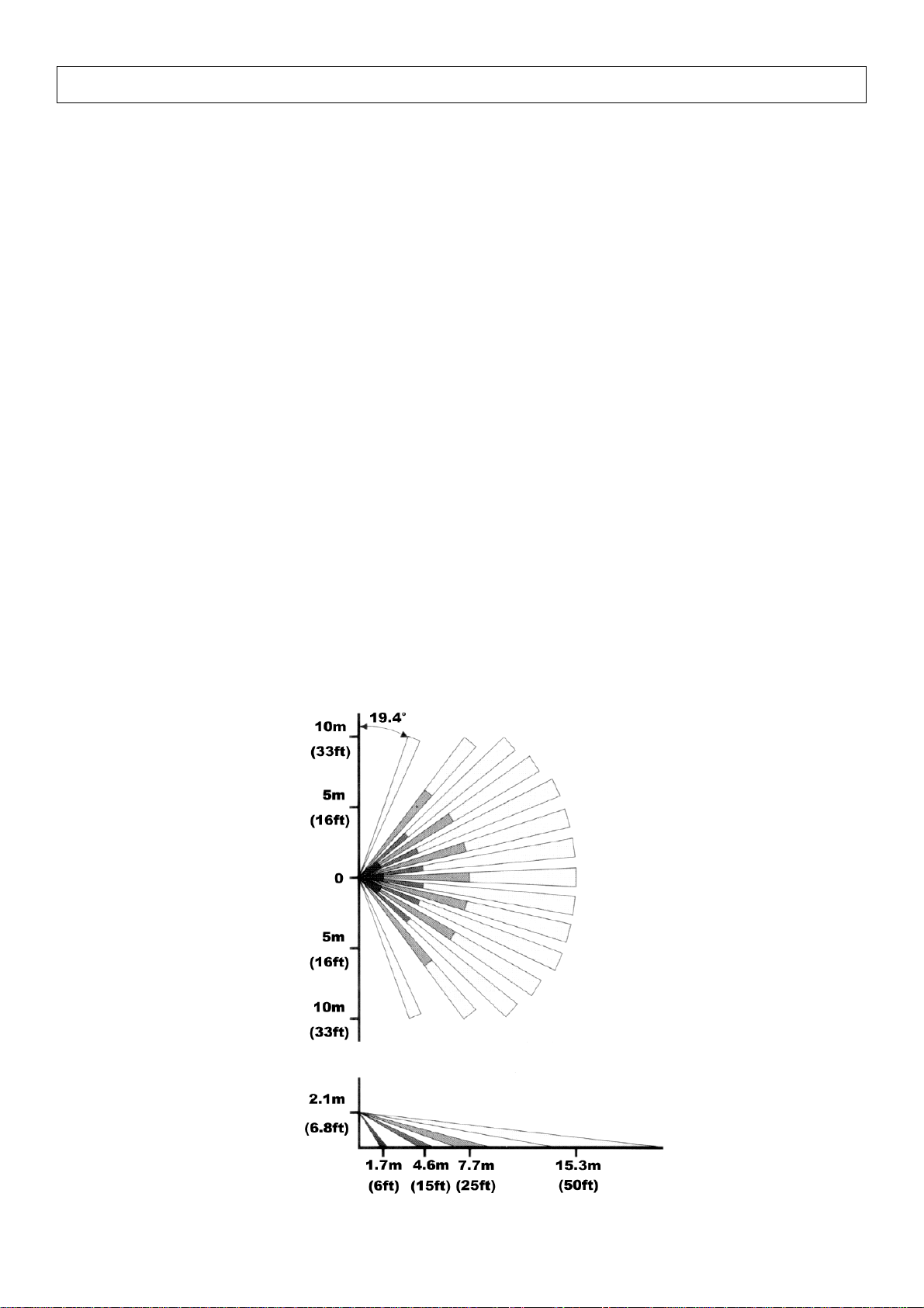
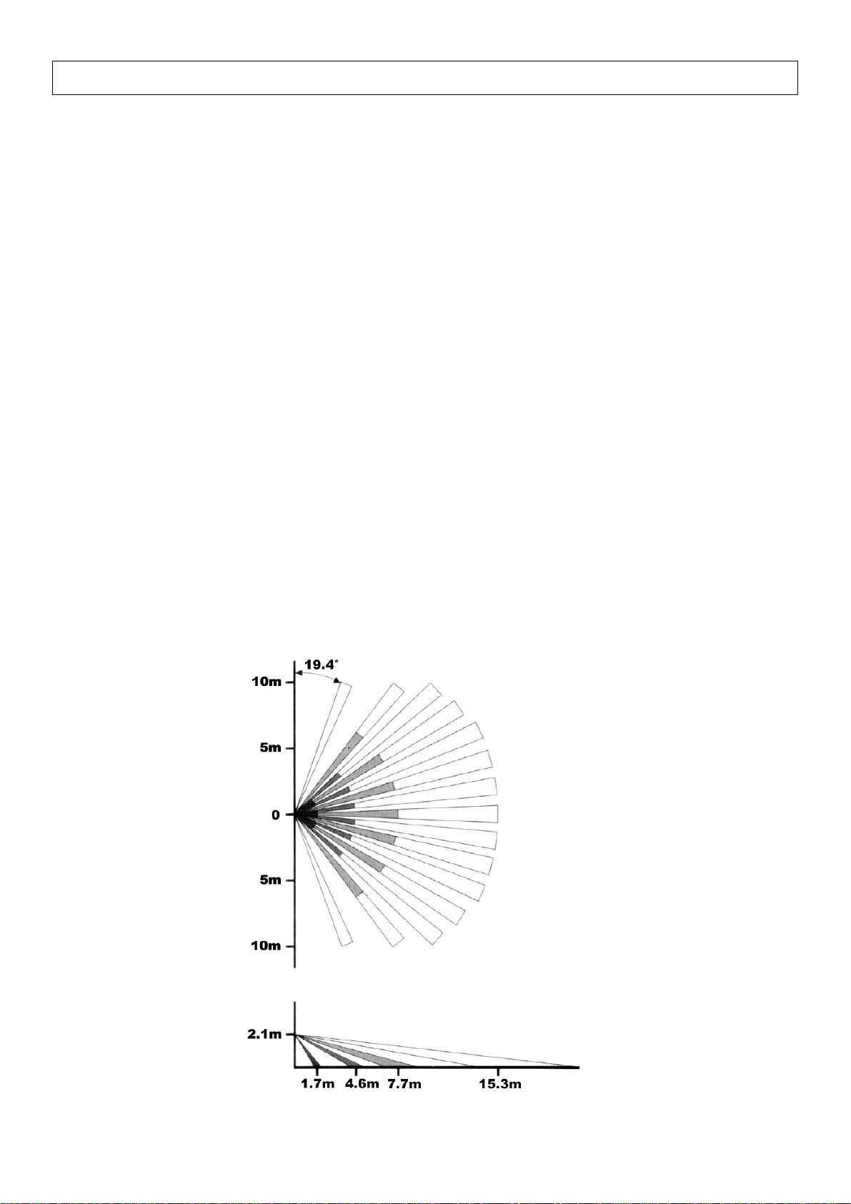
3. Detection Pattern
HAA54 GB
2
Page 3
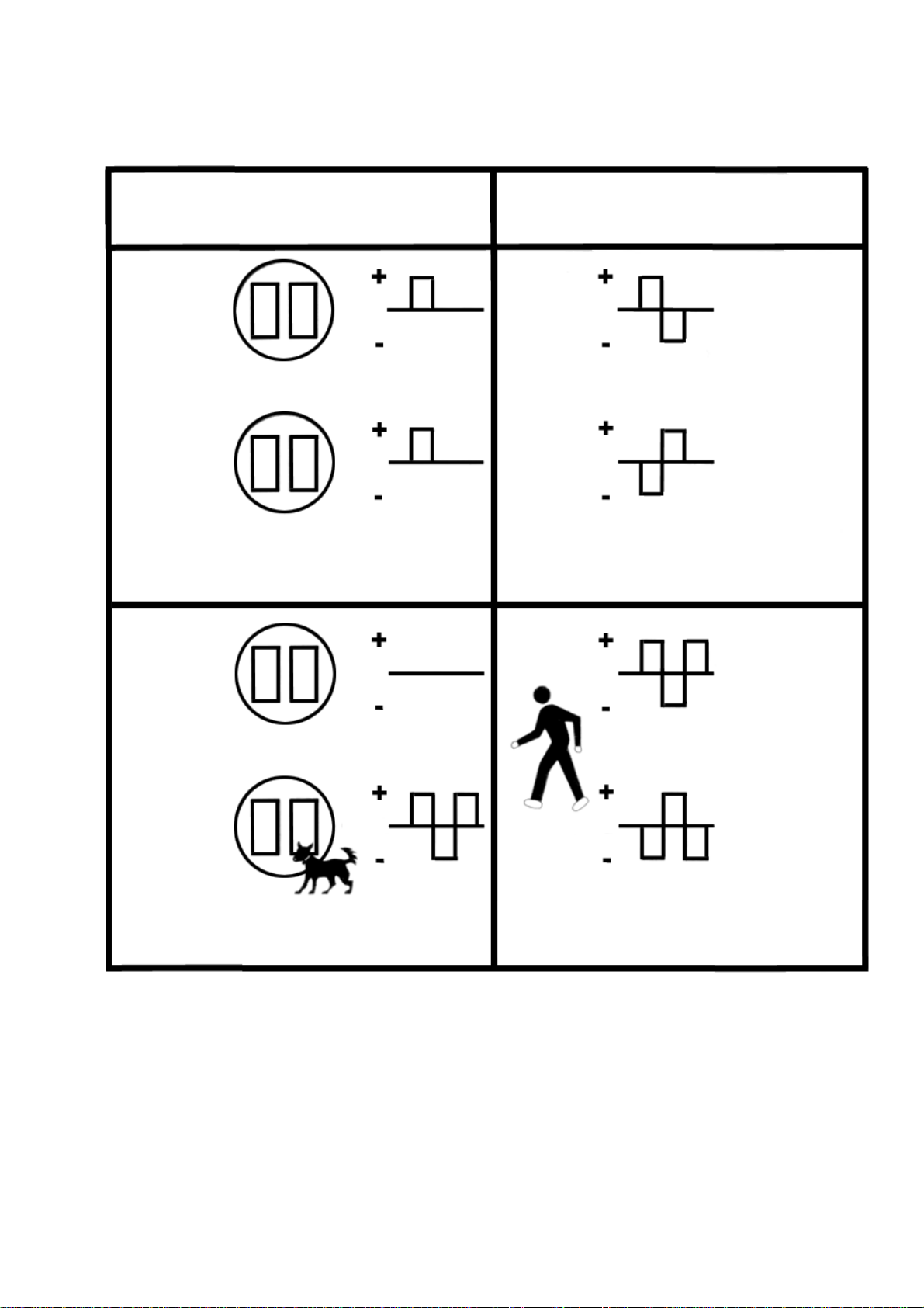
4. “Double-Twin Optics”-system : detection of changing polarity
HEAT
DETECTOR 1
HEAT
DETECTOR 2
Radio interference in "normal" mode
HEAT
DETECTOR 1
HEAT
DETECTOR 2
Only one channel is activated Both channels are activated
CH 1
CH 2
Changing polarity of the signal
CH 1
CH 2
ALARM NO ALARM
CH 1
CH 2
caused by the intruder
CH 1
CH 2
HAA54 GB
3
Page 4
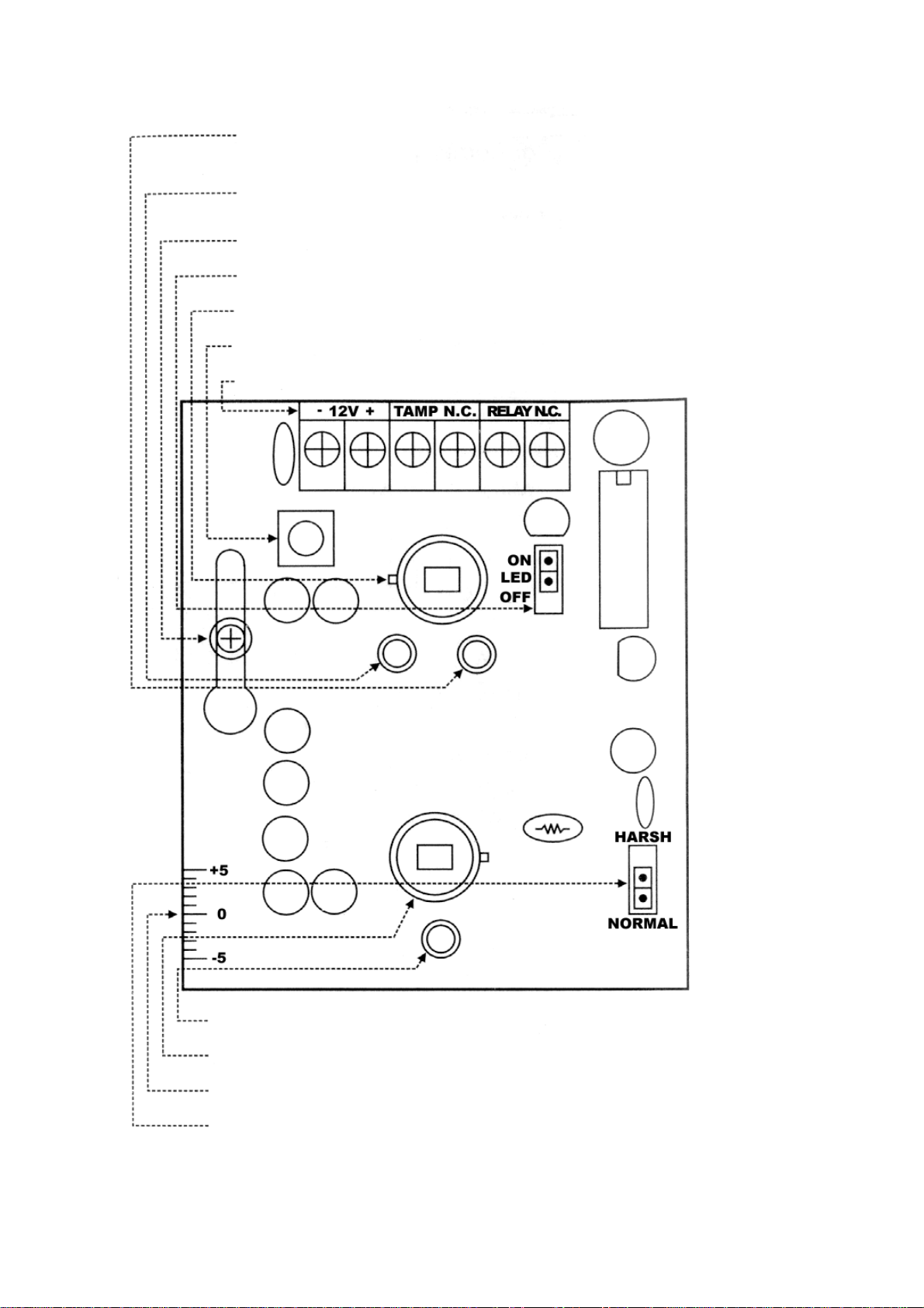
5. Layout of the PCB
LED2 : is activated upon detection by lower channel
LED1 : is activated upon detection by upper channel
PCB mounting screw
Jumper LED
Heat detector for the upper channel
Tamper switch
Terminal block
LED3 : alarm indicator
Heat detector for the lower channel
Adjustment of the vertical angle
Jumper for pulse counter
HAA54 GB
4
Page 5

a) Terminal Block
12V : Connect the positive terminal (+) to a power source of 9-16VDC on the alarm control
panel. Connect the negative terminal (-) to the grounding point of the control panel.
TAMPER N.C. : Connect these terminals to a 24hr N.C. (Normally Closed) protection zone of
the alarm control panel. The tamper switch contact is closed if the detector’s
front cover is in place. The contact will open and an alarm signal will instantly
be sent to the control panel if the front cover is removed at any time.
RELAY N.C. : This is the alarm output relay of the detector. These two terminals should be
connected to a N.C. protection zone of the alarm control panel.
b) Jumper Settings
LED : Place the jumper in the “ON”-position to arm all LEDs or place it in the “OFF”-position to
deactivate all LEDs. Detection is still possible with the jumper in the “OFF”-position.
PULSE : Place the pulse count jumper in the “NORMAL”-position for standard detection in a
stable environment. Place the pulse count jumper in the “HARSH”-position for double
detection within 12 seconds. Pets are ignored in this mode, which is particularly
useful if the device is installed in an unstable environment.
c) LED Indicators
LED 1 : “ON” upon detection by the upper channel
LED 2 : “ON” upon detection by the lower channel
LED 3 : “ON” when the alarm is activated, flashes during the warm-up delay
d) Adjustment of the Vertical Angle
Loosen the fixing screw of the PCB in order to move the PCB up or down. This enables the user
to adjust both the detection angle and the reach of the device while avoiding detection of small
(domestic) animals.
e) The Heat Detectors
This device is equipped with two heat detectors for motion detection. DO NOT TOUCH THE
HEAT DETECTORS !!
6. Installation
6.1. Mounting Location
• The detector can be mounted on a flat surface (e.g. a wall) or in a corner. Select a stable
surface.
• This detector should only be used indoors and should be installed in an environment that is
shielded from the elements.
• Do not expose the device to cold or warm air currents.
• Do not aim the detector at heating devices, air conditioning vents, windows, refrigerator or
freezer grilles or any other surface that is subject to violent and sudden changes in
temperature.
• Do not place large objects in front of the detector, as this will significantly diminish the area
protected by the detector’s beams.
HAA54 GB
5
Page 6

• Select a mounting location that allows you to place the detector at an angle of 45° (= optimal)
with reference to the intruder’s expected path. The detector should preferably be mounted in
a corner.
• Installation height : 2 to 3m (7 to 10ft).
6.2. Removing the Front Cover
1. Loosen the screw.
2. Insert the tip of a screwdriver into the latching slot and release the front cover.
3. Remove the front cover.
6.3. Removing the PCB
The PCB should be removed before mounting the back cover.
1. Loosen the fixing screw of the PCB.
2. Push the PCB upward until the head of the screw will pass through the opening.
3. Remove the PCB carefully.
6.4. Mounting the Back Cover
The back cover is suited for wall or corner mounting.
1. Feed the power cord through the push-out hole at the top and on the inside of the back
cover.
2. The push-out holes at the back are suitable for surface or wall mounting. The ones at the
sides are suitable for corner mounting.
3. Mount the back cover.
6.5. Mounting the Front Cover, Wiring
1. Reinsert the PCB and use the fixing screw to fix the PCB firmly.
2. Connect the wires to the terminal block.
3. Replace the front cover and make sure the tamper switch is depressed when the front cover
is clicked into place. Close the housing firmly with the fixing screw.
7. The “Walk Test”
1. The walk test can be performed as soon as the warm-up delay is finished, in other words
when the alarm LED stops flashing. The walk test is necessary in order to verify whether the
device is in good working order and whether it covers the desired area.
2. The alarm will sound when both the upper and lower channels are triggered simultaneously
when the jumper is in the “NORMAL” position.
3. If the jumper is in the “HARSH” position, the alarm will sound upon simultaneous and double
activation of both channels in a space of 12 seconds.
4. The detection range and the vertical angle of the device can be adjusted by sliding the PCB
up or down.
HAA54 GB
6
Page 7
8. Specifications
Current consumption : 15mA typical at 12VDC
Operating Voltage : 9-16VDC, 12VDC nominal
Detection Method : PIR detection with changing polarity, “Double –Twin
Optics” system
Warm-up Delay : 2 minutes typical, with flashing LED indication
Alarm Activation Delay : 2-3 seconds
Alarm Output : N.C. relay contact with a 10Ω resistor in series. Contact
rating : 28VDC, 0.1A
Walk-Test LEDs : For the upper and lower channels and for the alarm
indicators. Can be armed or disarmed at will
Pulse Counter : Normal response or 2 pulses within 12 seconds in the
“HARSH”-position
Tamper Switch : N.C. contact with a 10Ω resistor in series. Contact rating
: 12VDC, 50mA
Operating Temperature : -10 to +55°C with temperature compensation
Humidity : 95% non-condensing
EMC (electromagnetic compatibility) : conform to CE-label standards
Dimensions : 64 (W) x 45 (H) x 127 (L) mm
--------------------------
To all residents of the European Union
Important environmental information about this product
This symbol on the device or the package indicates that disposal of the device after its
lifecycle could harm the environment. Do not dispose of the unit (or batteries) as
unsorted municipal waste; it should be taken to a specialized company for recycling.
This device should be returned to your distributor or to a local recycling service. Respect
the local environmental rules.
If in doubt, contact your local waste disposal authorities.
HAA54 GB
7
Page 8
HAA54 – PIR BEWEGINGSDETECTOR
1. Beschrijving
De HAA54 gebruikt “Double-Twin Optics”-technologie en de beveiligingslogica wordt geleverd
door de ASIC-processor (Application Specific Integrated Circuit), die speciaal voor deze
toepassing werd ontwikkeld.
Het Double-Twin Optics systeem verenigt twee optische structuren en twee warmtedetectors in
één behuizing. Deze warmtedetectors beschikken elk over een duo-element dat weinig ruis
produceert. Op deze manier wordt een detectiepatroon gecreëerd dat enkel reageert op
indringers en dat huisdieren of knaagdieren negeert.
Het Double-Twin Optics systeem wordt gestuurd door de ASIC-processor, die zorgt voor
detectie bij wisselende polariteit van een signaal. Dankzij deze techniek hebben beide kanalen
een hoge weerstand tegen radiostoring en stroomstoten. Bovendien beschikt de HAA54 dankzij
deze processor ook nog over een aantal andere functies : digitale pulstelling,
temperatuurcompensatie, inschakelvertraging en een alarmuitgang en -regelingen. Deze
kenmerken zorgen voor een optimale veiligheid en vormen een uitstekende bescherming tegen
valse alarmmeldingen.
2. Kenmerken
• “Double-Twin Optics” detectiesysteem
• Detectie bij wisselende polariteit van een signaal
• Beveiligingslogica is geïntegreerd in de ASIC-processor
• SMD-technologie, hogere weerstand tegen radiostoring (RFI) en elektromagnetische storing (EMI)
• Automatische temperatuurcompensatie
• Normale respons of pulstelling voor een moeilijke (“HARSH”) omgeving
3. Detectiepatroon
HAA54 GB
8
Page 9

4. “Double-Twin Optics”-systeem : detectie van wisselende polariteit
WARMTEDETECTOR 1
WARMTEDETECTOR 2
Radiostoring in "normale" mode
WARMTEDETECTOR 1
WARMTEDETECTOR 2
Eén kanaal wordt geactiveerd
KAN. 1
KAN. 2
KAN. 1
KAN. 2
KAN. 1
KAN. 2
Wisselende polariteit van het signaal
veroorzaakt door de indringer
KAN. 1
KAN. 2
Beide kanalen worden geactiveerd
ALARM GEEN ALARM
HAA54 GB
9
Page 10

5. Opmaak van de PCB
LED2 : gaat branden bij detectie door onderste kanaal
LED1 : gaat branden bij detectie door bovenste kanaal
Bevestigingsschroef van de PCB
LED van de jumper
Warmtedetector van het bovenste kanaal
Tamperschakelaar
Aansluitklemmen
LED3 : alarmindicator
Warmtedetector van het onderste kanaal
Regeling van de vertikale stand
Jumper voor pulstelling
HAA54 GB
10
Page 11

a) Aansluitklemmen
12V : Verbind de positieve aansluitklem (+) met een voedingsbron van 9-16VDC op het
controlepaneel van het alarm. Verbind de negatieve aansluitklem (-) met de aarding van
het controlepaneel.
TAMPER N.C. : Verbind deze aansluitklemmen met een N.C. (Normally Closed = Normaal
Gesloten) 24u-zone van het controlepaneel van het alarm. De anti-inbraak
schakeling is gesloten wanneer het frontpaneel van de detector op zijn plaats
zit. Het contact gaat open en een alarmsignaal wordt onmiddellijk verstuurd
naar het controlepaneel indien het frontpaneel wordt verwijderd.
N.C. RELAIS : Dit i s het alarm uitgangsrelais van de detector. Deze twee aansluitklemmen moeten
worden aangesloten op een N.C. zone van het controlepaneel van het alarm.
b) Regeling van de jumper
LED : Plaats de jumper in de “ON”-stand om alle LEDs op scherp te stellen of plaats hem in de
“OFF”-stand om alle LEDs te deactiveren. Detectie is nog steeds mogelijk indien de
jumper zich in de “OFF”-stand bevindt.
PULS : Plaats de pulsteller in de “NORMAL”-stand voor standaard detectie. Gebruik deze stand
indien het apparaat werd geïnstalleerd in een stabiele omgeving. Plaats de pulsteller in
de “HARSH”-stand (“moeilijk”) voor dubbele detectie binnen de 12 seconden. In deze
stand worden huisdieren genegeerd. Deze stand is bijzonder nuttig indien het apparaat
werd geïnstalleerd in een “moeilijke” of onstabiele omgeving.
c) LED Indicators
LED 1 : “ON” bij detectie door het bovenste kanaal
LED 2 : “ON” bij detectie door het onderste kanaal
LED 3 : “ON” bij alarmtoestand, knippert wanneer het toestel aan het opwarmen is
d) Regelen van de vertikale stand
Maak de bevestigingsschroef van de PCB los om de PCB naar boven of beneden te schuiven.
Zo kunt u de detectiehoek en de detectieafstand aanpassen en kunt u detectie van bv. kleine
(huis)dieren vermijden.
e) De warmtedetectors
Dit apparaat is uitgerust met twee warmtedetectors voor bewegingsdetectie. RAAK DEZE
DETECTORS NIET AAN !!
6. Installatie
6.1. Kiezen van een montageplaats
• De detector kan worden bevestigd aan de muur of in een hoekje. Kies een stabiel oppervlak.
• Deze detector is uitsluitend bestemd voor gebruik binnenshuis en moet worden geïnstalleerd
in een omgeving die beschermd is tegen de elementen.
• Installeer het apparaat niet in de buurt van warme of koude luchtstromen.
HAA54 GB
11
Page 12

• Richt de detector niet naar verwarmingselementen, ventilatieroosters, ramen, roosters van
koelkasten of diepvriezers of naar andere oppervlakken die onderhevig zijn aan plotse en
hevige temperatuurswijzigingen.
• Plaats geen grote voorwerpen voor de detector : ze beperken het detectiegebied.
• Kies een montageplaats die u toelaat om de detector te gebruiken onder een hoek van 45°
(optimaal) t.o.v. de plaats waar de ongewenste bezoeker vermoedelijk het beschermde
gebied zal binnendringen. De detector wordt bij voorkeur gemonteerd in een hoekje.
• Montagehoogte : 2 tot 3m.
6.2. Verwijderen van het frontpaneel
1. Draai de schroef los.
2. Stop de punt van een schroevendraaier in de gleuf onder de bevestigingsschroef van de
behuizing en maak het frontpaneel los.
3. Verwijder het frontpaneel.
6.3. Verwijderen van de PCB
Verwijder de PCB vóór u het achterpaneel monteert.
1. Maak de bevestigingsschroef van de PCB los.
2. Duw de PCB naar boven tot de kop van de schroef door de opening kan.
3. Verwijder de PCB voorzichtig.
7.4. Monteren van het achterpaneel
Het achterpaneel is geschikt voor montage op een plat oppervlak of in een hoekje.
1. Stop de voedingskabel door de uitsparing bovenaan en aan de binnenkant van het
achterpaneel.
2. De uitsparingen aan de achterkant zijn geschikt voor montage op een plat oppervlak. De
uitsparingen aan de zijkant zijn geschikt voor montage in een hoek.
3. Monteer het achterpaneel.
7.5. Bedrading en aanbrengen van het frontpaneel
1. Breng de PCB terug op zijn plaats en draai de bevestigingsschroef stevig dicht.
2. Verbind de draden met de aansluitklemmen.
3. Breng het frontpaneel aan en zorg ervoor dat de anti-inbraak schakelaar ingedrukt is
wanneer u het frontpaneel vastklikt. Draai de bevestigingsschroef stevig dicht om de
behuizing af te sluiten.
8. “Walk Test”
1. U kunt de test uitvoeren zodra de alarm LED niet meer knippert, d.w.z. zodra de HAA54 is
opgewarmd. Deze test is noodzakelijk om na te gaan of de HAA54 bedrijfsklaar is en om te
bepalen of het toestel het gewenste detectiegebied volledig bestrijkt.
2. Het alarm gaat af wanneer beide kanalen gelijktijdig worden geactiveerd wanneer de jumper
van de pulsteller in de “NORMAL”-stand staat.
3. Wanneer de jumper van de pulsteller in de “HARSH”-stand staat, gaat het alarm slechts af
wanneer de beide kanalen 2 keer tegelijk worden geactiveerd binnen een tijdspanne van 12
seconden.
4. U moet de PCB naar boven of beneden schuiven om het detectiebereik en de vertikale stand
van de HAA54 aan te passen.
HAA54 GB
12
Page 13

8. Specificaties
Stroomverbruik : 15mA typisch bij 12VDC
Bedieningspanning : 9-16VDC, 12VDC nominaal
Detectiemethode : PIR detectie met wisselende polariteit, “Double-Twin
Optics” systeem
Opwarmingstijd : typisch : 2 minuten, met knipperende LED
Inschakelvertraging alarm : 2-3 seconden
Alarmuitgang : N.C. relaiscontact met een weerstand in serie van 10Ω. Vermogen :
28VDC, 0.1A
Detectie (walk-test LEDs) LEDs : Voor het onderste en bovenste kanaal en voor de
alarmindicators. Kunnen worden uitgeschakeld
Pulsteller : Normale respons of 2 impulsen binnen de 12
seconden in de “HARSH”-stand
Tamperschakelaar : N.C. contact met een weerstand in serie van 10Ω.
Vermogen : 12VDC, 50mA
Bedieningstemperatuur : -10 tot +55°C met temperatuurcompensatie
Vochtigheid : 95% niet-condenserend
EMC (elektromagnetische compatibiliteit) : conform de normen voor het CE-label
Afmetingen : 64 (B) x 45 (H) x 127 (L) mm
---------------------------
Aan alle ingezetenen van de Europese Unie
Belangrijke milieu-informatie betreffende dit product
Dit symbool op het toestel of de verpakking geeft aan dat, als het na zijn levenscyclus
wordt weggeworpen, dit toestel schade kan toebrengen aan het milieu. Gooi dit toestel
(en eventuele batterijen) niet bij het gewone huishoudelijke afval; het moet bij een
gespecialiseerd bedrijf terechtkomen voor recyclage. U moet dit toestel naar uw verdeler
of naar een lokaal recyclagepunt brengen. Respecteer de plaatselijke milieuwetgeving.
Hebt u vragen, contacteer dan de plaatselijke autoriteiten inzake verwijdering.
HAA54 GB
13
Page 14

HAA54 – DETECTEUR D’INTRUSION PASSIF A INFRAROUGE
1. Description
Le HAA54 utilise la technologie “Double-Twin Optics” et la logique de sécurité est livrée par le
processeur ASIC (Application Specific Integrated Circuit), conçu spécialement pour cette
application.
Le système Double-Twin Optics combine deux structures optiques et deux détecteurs de
chaleur dans un seul boîtier. Chacun des détecteurs dispose de deux éléments jumelés qui ne
produisent qu’un léger bruissement. La combinaison de ces éléments crée un mode de
détection qui réagit uniquement en cas d’intrusion et qui néglige les animaux domestiques et les
rongeurs.
Le système Double-Twin Optics est piloté par le processeur ASIC, qui assure la détection
lorsque le signal change de polarité. Grâce à cette technique, les deux canaux ont une
immunité importante aux parasites et aux pointes de courant. Grâce au processeur ASIC, le
HAA54 dispose en plus d’une gamme étendue de fonctions additionnelles : compteur
numérique d’impulsions, compensation de température, temporisation d’activation, une sortie
d’alarme et des réglages d’alarme. Ces caractéristiques permettent d’optimaliser la sécurité et
offrent une protection plus qu’adéquate contre les fausses alertes.
2. Caractéristiques
• Système de détection “Double-Twin Optics”
• Détection lorsque la polarité du signal change
• La logique de sécurité est intégrée dans le processeur ASIC
• Technologie SMD, une résistance accrue contre les perturbations radiophoniques (RFI) et
les perturbations électromagnétiques (EMI)
• Compensation automatique de la température
• Réponse normale ou comptage d’impulsions pour les environnements difficiles (“HARSH”) ou
instables.
3. Mode de détection
HAA54 GB
14
Page 15

4. Système “Double–Twin Optics” : détection de polarité changeante
DETECTEUR
DE CHALEUR 1
DETECTEUR
DE CHALEUR 2
Parasites dans le mode "normal"
DETECTEUR
DE CHALEUR 1
DETECTEUR
DE CHALEUR 2
Un des deux canaux est activé
CAN. 1
CAN. 2
Polarité changeante du signal
CAN. 1
CAN. 2
ALARME PAS D’ ALARME
CAN. 1
CAN. 2
causée par l’intrus
CAN. 1
CAN. 2
Les deux canaux sont activés
HAA54 GB
15
Page 16

5. Schéma du circuit imprimé
LED2 : s’allume lors de détection par le canal inférieur
LED1 : s’allume lors de détection par le canal supérieur
Ecrou de fixation du circuit imprimé
LED du cavalier
Détecteur de chaleur du canal supérieur
Interrupteur anti-sabotage (TAMPER)
Bornes de connexion
LED3 : indicateur d’alarme
Détecteur de chaleur du canal inférieur
Réglage de la position verticale
Cavalier pour comptage d’impulsions
HAA54 GB
16
Page 17

a) Bornes de connexion
12V : Branchez la borne positive (+) à une source d’alimentation de 9-16VCC qui se trouve sur
le panneau de commande de l’alarme. Branchez la borne négative (-) à la masse du
panneau de commande.
TAMPER N.C. : Vous devez connecter ces bornes de connexion à une zone 24h N.C. (Normally
Closed = Normalement Fermé) du panneau de commande de l’alarme. Le
contact anti-intrusion (TAMPER) est fermé si le panneau frontal du détecteur
est en place. Le contact s’ouvre et un signal d’alarme est immédiatement
envoyé vers le panneau de commande lorsque le panneau frontal est enlevé.
RELAIS N.C. : Le sortie relais alarme du détecteur. Ces deux bornes de connexion doivent être
connectées à une zone N.C. du panneau de commande de l’alarme.
b) Réglage du cavalier
LED : Placez le cavalier dans la position “ON” afin d’armer les LEDs ; mettez-le dans la
position “OFF” afin de désactiver les LEDs. Néanmoins, l’appareil est toujours capable
de détecter des hôtes indésirables avec le cavalier dans la position “OFF”.
IMPULSIONS : Mettez le compteur d’impulsions dans la position “NORMAL” po ur le mode de
détection standard. Ce mode est très pratique si l’appareil est installé dans un
environnement stable. Placez le compteur d’impulsions dans la position “HARSH”
(difficile) pour une double détection dans les 12 secondes. Ceci constitue la
position la plus pratique si l’appareil est installé dans un environnement difficile ou
instable. Les animaux domestiques sont ignorés dans ce mode.
c) Indicateur LED
LED 1 : “ON” lors de détection par le canal supérieur
LED 2 : “ON” lors de détection par le canal inférieur
LED 3 : “ON” en cas d’alarme, clignote pendant que l’appareil chauffe
d) Réglage de la position verticale
Dévissez l’écrou de fixation du circuit imprimé pour glisser le circuit imprimé en haut ou en bas,
ce qui permet de modifier l’angle de détection et la portée de l’appareil. Ceci permet également
d’éviter les fausses alertes causées par des animaux domestiques ou des rongeurs.
e) Les détecteurs de chaleur
Cet appareil est équipé de deux détecteurs de chaleur pour la détection de mouvements. NE
TOUCHEZ PAS AUX DETECTEURS !!
6. Montage
6.1. Sélection d’un lieu de montage
• Le détecteur convient pour montage mural ou en angle. Choisissez une surface stable.
• Le HAA54 s’utilise uniquement à l’intérieur et doit être installé dans un environnement qui est
à l’abri des éléments.
• Evitez d’installer l’appareil à proximité de courants d’air chaud ou froid.
HAA54 GB
17
Page 18

• Le détecteur ne peut pas être orienté vers des conduits de chauffage, des grilles de
ventilation, des fenêtres extérieures, les grilles de congélateurs ou de réfrigérateurs ou vers
toute autre surface qui est sujette à des variations de température soudaines et violentes.
• Evitez de placer des objets volumineux devant le détecteur comme ceux-ci réduisent
considérablement le champ de surveillance en gênant les rayons du détecteur.
• Choisissez un lieu de fixation qui permet d’utiliser le détecteur sous un angle de 45° (angle
optimal) vis-à-vis de l’endroit ou l’intrus entrera probablement le champ de surveillance. De
préférence, le détecteur est monté en angle.
• Hauteur de fixation : 2 à 3m.
6.2. Comment enlever le panneau frontal
1. Dévissez l’écrou.
2. Insérez la pointe du tournevis dans la cannelure en dessous de l’écrou de fixation du boîtier
et dégagez le panneau frontal.
3. Enlevez le panneau frontal.
6.3. Comment enlever le circuit imprimé
Enlevez le circuit imprimé avant de monter le panneau arrière.
1. Déserrez l’écrou de fixation du circuit imprimé.
2. Poussez le circuit imprimé en haut jusqu’à ce que la tête de l’écrou passe par le trou.
3. Enlevez le circuit imprimé prudemment.
8.4. Montage du panneau arrière
Le panneau arrière convient pour montage mural ou en angle.
1. Insérez le câble d'alimentation dans le trou défonçable en haut et à l’intérieur du panneau arrière.
2. Les trous défonçables à l’arrière conviennent pour le montage sur une surface plate. Les
trous défonçables sur le côté conviennent pour le montage en angle.
3. Installez le panneau arrière.
8.5. Câblage et installation du panneau frontal
1. Remettez le circuit imprimé en place et serrez l’écrou de fixation.
2. Branchez les fils aux bornes de connexion.
3. Installez le panneau frontal en veillant à ce que l’interrupteur anti-intrusion (TAMPER) soit
enfoncé. Serrez l’écrou de fixation.
7. Test de l’appareil ("Walk Test")
1. Vous pouvez exécuter ce test dès que l’appareil a chauffé, c.-à-d. dès que la LED d’alarme
ne clignote plus. Le test est indispensable pour vérifier si l’appareil est en état de marche et
si toute la zone de détection est protégée.
2. L’alarme se déclenche lorsque les deux canaux sont activés simultanément quand le cavalier
du compteur d’impulsions est fixé dans la position “NORMAL”.
3. Si le cavalier est fixé dans la position “HARSH”, l’alarme sera uniquement déclenchée lors
d'une double activation simultanée des canaux dans les 12 secondes.
4. Vous devez glisser le circuit imprimé en haut ou en bas afin de modifier la portée et la
position verticale de l’appareil.
HAA54 GB
18
Page 19

8. Spécifications
Consommation de courant : 15mA typique à 12VCC
Tension d’opération : 9-16VCC, 12VCC nominal
Mode de détection : détection PIR avec polarité changeante, système "Double-Twin
Optics"
Délai d’échauffement : typique : 2 minutes, avec indication par LED
clignotante
Temporisation d’activation de l'alarme : 2-3 secondes
Sortie d’alarme : Contact relais N.F. avec une résistance en série de
10Ω. Puissance : 28VDC, 0.1A
LEDs de détection : Pour le canal supérieur et inférieur comme pour les
indicateurs d’alarme. Peuvent être désactivées.
Compteur d’impulsions : Réponse normale ou 2 impulsions dans les 12
secondes dans la position “HARSH”
Interrupteur anti-sabotage (TAMPER) : Contact N.F. avec une résistance en série de 10Ω.
Puissance : 12VDC, 50mA
Température d’opération : -10 à +55°C avec compensation de température
Humidité : 95% non condensant
EMC (compatibilité électromagnétique) : selon les normes du label CE
Dimensions : 64 (La) x 45 (H) x 127 (Lo) mm
-----------------------------
Aux résidents de l'Union européenne
Des informations environnementales importantes concernant ce produit
Ce symbole sur l'appareil ou l'emballage indique que l’élimination d’un appareil en fin de
vie peut polluer l'environnement. Ne pas éliminer un appareil électrique ou électronique
(et des piles éventuelles) parmi les déchets municipaux non sujets au tri sélectif ; une
déchèterie traitera l’appareil en question. Renvoyer les équipements usagés à votre
fournisseur ou à un service de recyclage local. Il convient de respecter la réglementation locale
relative à la protection de l’environnement.
En cas de questions, contacter les autorités locales pour élimination.
HAA54 GB
19
Page 20

HAA54 – DETECTOR DE MOVIMIENTO PIR
1. Descripción
El HAA54 utiliza la tecnología “Double-Twin Optics”. La lógica de seguridad se suministra por el
procesador ASIC (Application Specific Integrated Circuit), diseñado especialmente para esta
aplicación.
El sistema Double-Twin Optics combina dos estructuras ópticas y dos sensores de calor en una
sola caja. Cada sensor de calor dispone de dos elementos que producen poco ruido. La
combinación de estos elementos crea un modo de detección que reacciona sólo en caso de
intrusión e ignora animales domésticos y roedores.
El sistema Double-Twin Optics está pilotado por el procesador ASIC, que asegura la detección
si la señal cambia de polaridad. Gracias a esta técnica, los dos canales tienen una gran
inmunidad a las interferencias y las pulsaciones eléctricas. Gracias al procesador ASIC, el
HAA54 tiene además una gran gama de funciones adicionales: un contador digital de pulsos,
una compensación de variaciones de temperatura, una temporización de activación, una salida
de alarma y ajustes de alarma. Estas características permiten optimizar la seguridad y ofrecen
una excelente protección contra las falsas alarmas.
2. Características
• Sistema de detección “Double-Twin Optics”
• Detección si la polaridad de la señal cambia
• La lógica de seguridad está integrada en el procesador ASIC
• Tecnología SMD, una resistencia más grande a las interferencias RFI y las interferencias
electromagnéticas (EMI)
• Compensación automática de temperatura
• Respuesta normal o cuenta de pulsos para lugares difíciles (“HARSH”) o inestables.
3. Modo de detección
HAA54 GB
20
Page 21

4. Sistema “Double–Twin Optics”: detección de polaridad cambiante
SENSOR
DE CALOR 1
SENSOR
DE CALOR 2
Interferencias en el modo
"normal"
SENSOR
DE CALOR 1
SENSOR
DE CALOR 2
Uno de los dos canales está
activado
CAN. 1
CAN. 2
Polaridad cambiante de la señal
CAN. 1
CAN. 2
Los dos canales están activados
ALARMA NO ALARMA
CAN. 1
CAN. 2
causada por el intruso
CAN. 1
CAN. 2
HAA54 GB
21
Page 22

5. Esquema del CI
LED2: se ilumina si el canal inferior detecta algo
LED1: se ilumina si el canal superior detecta algo
Tornillo de fijación del CI
LED del puente
Sensor de calor del canal superior
Contacto antisabotaje (TAMPER)
Bornes de conexión
LED3: indicador de alarma
Sensor de calor del canal inferior
Ajuste de la posición vertical
Puente para la cuenta de pulsos
HAA54 GB
22
Page 23

a) Bornes de conexión
12V : Conecte el borne positivo (+) a una fuente de alimentación de 9-16VCC que se encuentra
en el panel de control de la alarma. Conecte el borne negativo (-) a la masa del panel de
control.
TAMPER N.C. : Conecte estos bornes de conexión a una zona 24h N.C. (Normally Closed =
Normalmente Cerrado) del panel de control de la alarma. El contacto
antisabotaje (TAMPER) está cerrado si el panel frontal del detector está
cerrado. El contacto se abre y se envía inmediatamente una señal de alarma al
panel de control si se quita el panel frontal.
RELAIS N.C. : La salida relé alarma del detector. Conecte estos dos bornes de conexión a una
zona N.C. del panel de control de la alarma.
b) Ajustar el puente
LED : Coloque el puente en la posición “ON” para armar los LEDs; colóquelo en la posición
“OFF” para desactivar los LEDs. No obstante, el aparato continúa detectando con el
puente en la posición “OFF”.
PULSOS : Coloque el contador de pulsos en la posición “NORMAL” para el modo de
detección estándar. Este modo es muy práctico si el aparato ha sido instalado en
un lugar estable. Coloque el contador de pulsos en la posición “HARSH” (difícil)
para una doble detección dentro de los 12 segundos. Esta posición es la más
práctica si el aparato ha sido instalado en un lugar difícil o inestable. Los animal es
domésticos son ignorados en este modo.
c) Indicador LED
LED 1 : “ON” el canal superior detecta algo
LED 2 : “ON” el canal inferior detecta algo
LED 3 : “ON” en caso de alarma, parpadea mientras que el aparato se calienta
d) Ajustar la posición vertical
Desatornille el tornillo de fijación del CI para deslizar el CI hacia arriba o hacia abajo. Esto
permite modificar el ángulo de detección y el alcance del aparato. Esto permite también evitar
las falsas alarmas causadas por animales domésticos o roedores.
e) Los sensores de calor
Este aparato está equipado con dos sensores de calor para la detección de movimientos. ¡¡NO
TOQUE LOS SENSORES!!
6. Montaje
6.1. Seleccionar un lugar de montaje
• El detector es apto para montaje mural o en ángulo. Seleccione una superficie estable.
• El HAA54 se utiliza sólo en interiores y debe instalarse en un lugar protegido de los
elementos.
• No exponga el aparato a corrientes de aire calientes o frías.
HAA54 GB
23
Page 24

• No dirija el aparato hacia aparatos de calefacción, rejillas de ventilación, ventanas exteriores,
rejillas de congeladores o neveras ni hacia cualquier superficie sujeta a variaciones de
temperatura repentinas y violentas.
• No coloque objetos voluminosos delante del detector porque disminuyen la zona de
detección.
• Seleccione un lugar de montaje que permita utilizar el detector bajo un ángulo de 45° (ángulo
óptimo) con respecto al lugar donde el intruso probablemente entrara en el campo de
vigilancia. Monte el detector preferentemente en un ángulo.
• Altura de fijación: de 2 a 3m.
6.2. Quitar el panel frontal
1. Desatornille el tornillo.
2. Introduzca la punta del destornillador en la ranura debajo del tornillo de fijación de la caja y
suelte el panel frontal.
3. Quite el panel frontal.
6.3. Quitar el CI
Quite el CI antes de montar el panel posterior.
1. Desatornille el tornillo de fijación del CI.
2. Empuje el CI hacia arriba hasta que el cabezal del tornillo pase por el agujero.
3. Quite el CI cuidadosamente.
8.6. Montar el panel posterior
El panel posterior es apto para montaje mural o en ángulo.
1. Introduzca el cable de alimentación en el agujero y en el interior del panel posterior.
2. Los agujeros de la parte posterior son aptos para el montaje en una superficie plana. Los
agujeros laterales son aptos para el montaje en ángulo.
3. Monte el panel posterior.
8.7. Cableado e instalación del panel frontal
1. Vuelva a colocar el CI y apriete el tornillo de fijación.
2. Conecte los hilos a los bornes de conexión.
3. Instale el panel frontal asegurándose de que el interruptor antisabotaje (TAMPER) esté
pulsado. Apriete el tornillo de fijación.
7. Prueba del aparato ("Walk Test")
1. Es posible realizar esta prueba tan pronto como el aparato se haya calentado, es decir, en
cuanto el LED de alarma ya no parpadee. La prueba es necesaria para verificar si el aparato
funciona y si toda la zona de detección está protegida.
2. La alarma se activa si los dos canales se activan simultáneamente si el puente del contador
de pulsos está en la posición “NORMAL”.
3. Si el puente está en la posición “HARSH”, la alarma sólo se activará si hay una doble
activación simultánea de los canales dentro de los 12 segundos.
4. Deslice el CI hacia arriba o hacia abajo para modificar el alcance y la posición vertical del
aparato.
HAA54 GB
24
Page 25

8. Especificaciones
Consumo de corriente : 15mA típico a 12VCC
Alimentación : 9-16VCC, 12VCC nominal
Modo de detección : detección PIR con polaridad cambiante, sistema "Double-Twin
Optics"
Tiempo de calentamiento : típico: 2 minutos, con indicación por LED intermitente
Temporización de activación de la alarma : 2-3 segundos
Salida de la alarma : Contacto relé N.C. con una resistencia en serie de
10Ω. Potencia: 28VDC, 0.1A
LEDs de detección : Tanto para el canal superior e inferior como para los
indicadores de alarma. Es posible desactivarlos.
Contador de pulsos : Respuesta normal o 2 pulsos dentro de los 12
segundos en la posición “HARSH”
Interruptor antisabotaje (TAMPER) : Contacto N.C. con una resistencia en serie de 10Ω.
Potencia: 12VDC, 50mA
Temperatura de funcionamiento : de -10 a +55°C con compensación de temperatura
Humedad : 95% no condensación
EMC (compatibilidad electromagnética) : según las normas de la etiqueta CE
Dimensiones : 64 (An) x 45 (Al) x 127 (Lo) mm
---------------------------------
A los ciudadanos de la Unión Europea
Importantes informaciones sobre el medio ambiente concerniente este producto
Este símbolo en este aparato o el embalaje indica que, si tira las muestras inservibles,
podrían dañar el medio ambiente. No tire este aparato (ni las pilas eventuales) en la
basura doméstica; debe ir a una empresa especializada en reciclaje. Devuelva este
aparato a su distribuidor o un lugar de reciclaje local. Respete las leyes locales en relación con
el medio ambiente.
Si tiene dudas, contacte las autoridades locales para eliminación.
HAA54 GB
25
Page 26

HAA54 – PIR-BEWEGUNGSMELDER
1. Beschreibung
Der HAA54 verwendet “Double-Twin Optics”-Technologie und die Sicherheitslogik wird von dem
ASIC-Prozessor (Application Specific Integrated Circuit), der für diese spezifische Applikation
entwickelt wurde, verschafft.
Das 'Double-Twin Optics'-System kombiniert zwei optische Strukturen und Hitzemelder in einem
Gehäuse. Die beiden Hitzemelder sind mit einem Doppelelement, das nur wenig Geräusch
produziert, ausgestattet. Das ermöglicht dem HAA54, ein Erkunnungsmuster, das nur
Eindringlinge detektiert und Haus- oder Nagetiere ignoriert, zu entwickeln.
Das 'Double-Twin Optics'- System wird durch den ASIC-Prozessor gesteuert. Dieser Prozessor
detektiert die Polaritätsänderung eines Signals, das durch einen Eindringling verursacht wird.
Dank dieser Technik haben beide Kanäle eine große Unempfindlichkeit gegen gängige
Funkstörung und Stromstöße. Dieser Prozessor gibt dem HAA54 eine Menge zusätzliche
Funktionen: einen digitalen Impulszähler, Temperaturkompensation, Aufwärmzeit,
Alarmsteuerung und Alarmverzögerung. Diese Eigenschaften maximieren die Sicherheit und sind
ein ausgezeichneter Schutz vor falschem Alarm.
2. Eigenschaften
• “Double-Twin Optics” Detektionssystem
• Detektion mit Polaritätsänderung des Signals
• Sicherheitslogik ist in den ASIC-Prozessor integriert
• SMD-Technologie bietet größere EMI (electromagnetic immunity - elektromagnetische
Unempfindlichkeit) und besseren Schutz vor RFI (radio frequency interference - Funkstörung)
• Automatische Temperaturkompensation
• Normale Reaktion oder Impulszählung für “HARSH” (unstabile) Umgebungen
3. Erkunnungsmuster
HAA54 GB
26
Page 27

4. “Double-Twin Optics”-System: Detektion der Polaritätsänderung
HITZE-
DETEKTOR 1
HITZE-
DETEKTOR 2
HITZEDETEKTOR 1
HITZE-
DETEKTOR 2
KEIN ALARM
KAN. 1
KAN. 1
KAN. 2
Funkstörung im 'normalen' Modus
KAN. 1
KAN. 2
Nur 1 Kanal ist aktiviert Beide Kanäle sind aktiviert
KAN. 2
Polaritätsänderung durch
Eindringling verursacht
KAN. 1
KAN. 2
ALARM
HAA54 GB
27
Page 28

5. Lay-Out der Leiterplatte
LED2: wird bei Detektion auf dem unteren Kanal aktiviert
LED
1: wird bei Detektion auf dem oberen Kanal aktiviert
PCB Montageschraube
Jumper-LED
Hitzedetektor für den oberen Kanal
Manipulationssicherung
Anschlussleiste
LED3: Alarmanzeige
Hitzedetektor für den unteren Kanal
Regelung des vertikalen Winkels
Jumper für Impulszähler
HAA54 GB
28
Page 29

a) Anschlussleiste
12V : Verbinden Sie den positiven Anschluss (+) an einer Spannungsquelle von 9-16VDC auf
der Bedienkonsole des Alarms. Verbinden Sie den negativen Anschluss (-) an den
Erdungspunkt der Bedienkonsole.
TAMPER N.C. : Verbinden Sie diese Anschlüsse mit einer 24hr N.C. (Normally Closed)
Schutzzone der Alarmbedienkonsole. Der Manipulationssicherungskontakt ist
geschlossen wenn die Frontplatte des Detektors eingerastet ist. Der Kontakt
wird geöffnet werden und ein Alarmsignal wird sofort zur Bedienkonsole
gesendet werden, sobald die Frontplatte entfernt wird.
RELAIS N.C. : Dies ist das Alarmausgangsrelais des Detektors. Diese 2 Anschlüsse müssen
mit einer N.C. Schutzzone der Alarmbedienkonsole verbunden werden.
b) Jumpereinstellungen
LED : Stellen Sie den Jumper auf die “ON”-Position um alle LEDs scharf zu stellen oder auf
die“OFF”-Position um alle LEDs zu deaktivieren. Detektion ist noch immer möglich mit
den LEDs in der “OFF”-Position.
PULSE : Stellen Sie den Jumper des Impulszählers auf die “NORMAL”-Position für
Standarddetektion in einer stabilen Umgebung. Stellen Sie den Jumper des
Impulszählers auf die “HARSH”-Position für doppelte Detektion innerhalb von 12
Sekunden. Haustiere werden in diesem Modus ignoriert, was sehr nützlich ist in
unstabilen Umgebungen.
c) LED-Anzeigen
LED 1 : “ON” bei Detektion im oberen Kanal
LED 2 : “ON” bei Detektion im unteren Kanal
LED 3 : “ON” wenn der Alarm aktiviert ist, blinkt diese LED während der Einschaltverzögerung.
d) Regelung des vertikalen Winkels
Drehen Sie die Montageschraube der Leiterplatte los um die Leiterplatte aufwärts oder abwärts
zu bewegen. So kann der Anwender den Detektionswinkel und die Reichweite des Geräts
regeln und die Detektion von kleinen (Haus) Tieren vermeiden.
e) Die Hitzedetektoren
Dieses Gerät ist mit 2 Hitzedetektoren für Bewegungsdetektion ausgestattet. BERÜHREN DIE
DIE HITZEDETEKTOREN NICHT !!
6. Installation
6.1. Montageort
• Der Detektor kann auf einer flachen Oberfläche (z.B. an einer Wand) oder in einer Ecke
montiert werden. Wählen Sie eine stabile Fläche.
• Dieser Detektor darf nur im Innenbereich verwendet werden und muss an einem
abgeschirmten Ort montiert werden.
• Das Gerät keinen warmen oder kalten Luftströmen aussetzen.
HAA54 GB
29
Page 30

• Richten Sie den Detektor nicht auf Heizgeräte, Luftdurchlässe einer Klimaanlage, Fenster
oder Gitter eines (Tief)Kühlschrankes oder andere Oberflächen die gegen
Temperaturschwankungen empfindlich sind.
• Stellen Sie keine großen Objekte vor dem Detektor, denn das verringert bedeutsam die
durch den Detektor geschützte Zone.
• Selektieren Sie einen Montageort, der es ermöglicht, den Detektor in einem Winkel von 45°
(= optimal) zu der erwarteten Bahn des Eindringlings zu montieren. Am besten montieren Sie
den Detektor in einer Ecke.
• Installationshöhe: 2 bis 3m (7 bis 10ft).
6.2. Frontplatte entfernen
1. Schrauben Sie die Schraube los.
2. Bringen Sie die Spitze eines Schraubendrehers in den Schlitz ein und entriegeln Sie die
Frontplatte.
3. Entfernen Sie die Frontplatte.
6.3. Leiterplatte entfernen
Die Leiterplatte muss entfernt werden, bevor Sie die Rückplatte montieren.
1. Schrauben Sie die Befestigungsschraube der Leiterplatte los.
2. Drücken Sie die Leiterplatte bis den Kopf der Schraube durch das Loch geht.
3. Entfernen Sie vorsichtig die Leiterplatte.
8.8. Die Rückplatte montieren
Die Rückplatte ist für Wand –oder Eckmontage geeignet.
1. Bringen Sie das Stromkabel durch an das Loch an der Ober- und Innenseite der Rückplatte.
2. Die Löcher an der Rückseite sind für Oberflächenmontage oder Wandmontage geeignet. Die
Löcher an der Seite sind für Eckmontage geeignet.
3. Montieren Sie die Rückplatte
8.9. Frontplatte montieren, Verkabelung
1. Bringen Sie die Leiterplatte wieder an und befestigen Sie die Leiterplatte mit der
Befestigungsschraube.
2. Verbinden Sie die Kabel mit der Anschlussleiste.
3. Bringen Sie die Frontplatte wieder an und sorgen Sie dafür, dass die Manipulationssicherung
eingedrückt ist wenn Sie die Frontplatte einrasten. Schließen Sie das Gehäuse mit der
Schraube.
9. “Walk Test”
1. Der "Walk Test" kann ausgeführt werden, sobald die Einschaltverzögerung fertig ist, mit
anderen Worten, wenn die Alarm-LED zu blinken aufhört. Der "Walk Test" ist notwendig um
zu prüfen, ob das Gerät betriebsfähig ist und es die gewählte Zone deckt.
2. Der Alarm wird ertönen wenn sowohl die obere als die untere Kanäle zur gleichen Zeit
ausgelöst werden wenn der Jumper in der “NORMAL” Position steht.
3. Wenn der Jumper in der “HARSH”-Position steht, wird der Alarm bei einer gleichzeitigen und
doppelten Aktivierung der beiden Kanäle in einer Zeitspanne von 12 Sekunden, ertönen.
4. Der Erfassungsbereich und der vertikale Winkel des Geräts können geregelt werden, indem
Sie die Leiterplatte auf- oder abwärts schieben.
HAA54 GB
30
Page 31

8. Technische Daten
Stromverbrauch : 15mA typisch bei 12VDC
Betriebsspannung : 9-16VDC, 12VDC nominal
Erfassungsmethode : Erfassung über wechselnde Polarität, 2
pyroelektronische Komponenten, PIR
Aufwärmzeit : 2 Minuten mit blinkender LED-Anzeige
Alarmverzögerung : 2-3 Sekunden
Alarmausgang : N.C-Relaiskontakt mit 10Ω seriellem Widerstand.
Kontaktleistung: 28VDC, 0.1A
Walk-Test LEDs : Für die oberen und unteren Kanäle und die Alarm-
Anzeigen. Können nach wunsch aktiviert oder deaktiviert
werden.
Impulszähler : Sofortiger Respons oder 2 Impulse innerhalb von
Sekunden
Manipulationsschalter : NC-Kontakt mit seriellem 10Ω Widerstand.
Kontaktleistung: 12VDC, 50mA
Betriebstemperatur : -10 bis +55°C mit Temperaturkompensation
Feuchte : 95% nicht kondensierend
EMC
(elektromagnetische Kompatibilität) : gemäß CD-Normen
Abmessungen : 64 (B) x 45 (H) x 127 (L) mm
----------------------------
An alle Einwohner der Europäischen Union
Wichtige Umweltinformationen über dieses Produkt
Dieses Symbol auf dem Produkt oder der Verpackung zeigt an, dass die Entsorgung
dieses Produktes nach seinem Lebenszyklus der Umwelt Schaden zufügen kann.
Entsorgen Sie die Einheit (oder verwendeten Batterien) nicht als unsortiertes Hausmüll;
die Einheit oder verwendeten Batterien müssen von einer spezialisierten Firma zwecks
Recycling entsorgt werden. Diese Einheit muss an den Händler oder ein örtliches RecyclingUnternehmen retourniert werden. Respektieren Sie die örtlichen Umweltvorschriften.
Falls Zweifel bestehen, wenden Sie sich für Entsorgungsrichtlinien an Ihre örtliche
Behörde.
HAA54 GB
31
 Loading...