

Page 1

HAA52N
PIR INTRUSION DETECTOR
PIR-DETECTOR
DÉTECTEUR PIR
DETECTOR PIR
PIR-DETEKTOR
USER MANUAL 3
GEBRUIKERSHANDLEIDING 7
NOTICE D’EMPLOI 11
MANUAL DEL USUARIO 15
BEDIENUNGSANLEITUNG 19
Page 2

Page 3
HAA52N
User manual
1. Introduction
To all residents of the European Union
Important environmental information about this product
This symbol on the device or the package indicates that disposal of the device after its
lifecycle could harm the environment. Do not dispose of the unit (or batteries) as
unsorted municipal waste; it should be taken to a specialized company for recycling. This
device should be returned to your distributor or to a local recycling service. Respect the
local environmental rules.
If in doubt, contact your local waste disposal authorities.
Thank you for choosing Velleman! Please read the manual thoroughly before bringing this device into
service. If the device was damaged in transit, do not install or use it and contact your dealer. Damage
caused by disregard of certain guidelines in this manual is not covered by the warranty and the
dealer will not accept responsibility for any ensuing defects or problems.
The HAA52N is a passive infrared intrusion detector for general purposes, designed to give a costeffective and reliable solution for residential and commercial security systems.
2. Safety Instructions
Keep the device away from children and unauthorised
users.
Indoor use only.
Keep this device away from rain, moisture, splashing and
dripping liquids.
• Damage caused by disregard of certain guidelines in this manual is not covered by the warranty and
the dealer will not accept responsibility for any ensuing defects or problems.
• Keep the device away from splashing and dripping liquids.
• Note that damage caused by user modifications to the device is not covered by the warranty.
3. General Guidelines
• Protect this device from shocks and abuse. Avoid brute force when operating the device.
• Protected the device against extreme temperatures, dust and moisture.
• Familiarise yourself with the functions of the device before actually using it.
• All modifications of the device are forbidden for safety reasons.
• Only use the device for its intended purpose. Using the device in an unauthorised way will void the
warranty.
4. Features
• dual low-noise pyro sensor
• alternate polarity signal processing
• security logics integrated into the MCU device
• SMT components for a greater EMI and RFI immunity
• normal or pulse count response
01 (10/10/2008)
3
Page 4
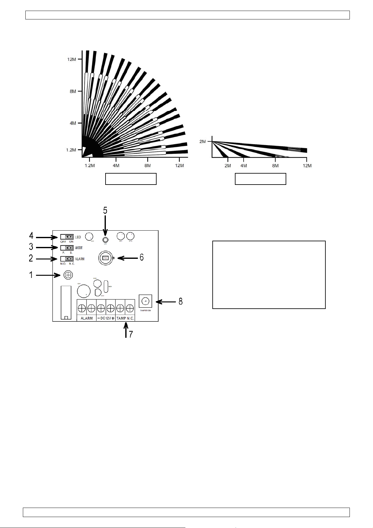
5. Coverage pattern
HAA52N
Top view Side view
6. PCB description
1. PCB fixing screw
2. Alarm output jumper
3. Pulse mode jumper
4. LED on/off jumper
5. Test/alarm indicator
6. Pyro sensor (do not touch!)
7. Connection terminal block
8. Tamper switch
a. Connection Terminal Description
ALARM This is the alarm relay output contact of the detector. It is selectable as NC or
NO via the alarm jumper to match the requirements of the protection zone.
DC12V Connect the positive (+) side to an 8V ~ 16V DC power source, usually from the
alarm control panel. Connect the negative (-) side to the common grounding
point of the control panel.
TAMP NC If a tamper switch is required, connect these terminals to a 24-hour NC
protection zone in the alarm control panel. The tamper switch contact is closed
with the detector’s front cover secured on the box. The opening of the front
cover at any time will make the contact open and send an immediate alarm
signal to the control panel.
01 (10/10/2008)
4
Page 5
HAA52N
b. Jumper Settings
LED ON Enables the LED
ON = alarm activated.
FLASH = power-up.
OFF Disables the LED. Does not affect detection.
MODE S Standard alternate polarity signal processing. For operation within a stable
environment.
P Double alternate polarity signal processing within 10 seconds. For a harsh
environment.
ALARM NC The alarm relay output contact is NC. The output relay is normally energized.
NO The alarm relay output contact is NO. The output relay is normally de-
energized.
7. Installation
a. Mounting Location
• The detector can be surface or corner mounted, or mounted with the supplies swivel bracket.
Always mount the unit on a sturdy surface.
• The detector should be mounted indoors, in areas that do not have openings constantly exposed
to the outside environment.
• Select the mounting location so that the expected movement of an intruder will cross the
detection beam.
• Do not locate the detector where hot or cold moving air will blow directly onto the unit.
• Avoid aiming the detector towards heating or air conditioning vents or ducts, exterior metal
walls, exterior windows or curtains covering windows, refrigerator or freezer grills or other
surfaces that may change temperature rapidly.
• Avoid putting large objects in front of the detector which will cause significant changes in the
area or volume protected.
• Select the mounting location so that the beam patterns are at a 45° angle to the intruder’s
expected path. Installation height should be 2 ~ 3m.
b. Front Cover Removal
Loosen the screw on the bottom of the box to release the front cover from the rear cover.
c. PCB Removal
It is necessary to remove the PCB before mounting the rear cover. Loosen the PCB fixing screw.
Pull out the PCB carefully.
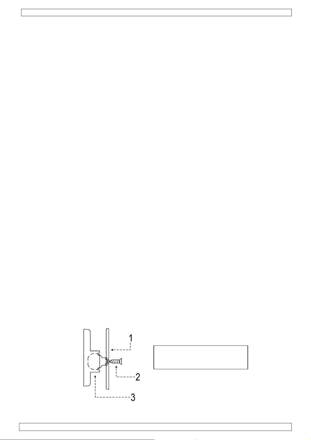
d. Rear Cover Mounting
The rear cover is prepared for either surface or corner mounting, or mounting with the supplied
swivel bracket.
• Punch the cable hole at the back of the rear cover, together with the fixing holes (knockout
holes) according to the mounting (surface or corner mounting, or mounting with the supplied
swivel bracket).
• Mount the rear cover or mount the swivel bracket with screws (mount the rear cover on the
swivel bracket afterwards).
1. Rear cover
2. Fixing screw
3. Swivel bracket
01 (10/10/2008)
5
Page 6

HAA52N
e. Wiring and Finishing
• Fix the PCB back onto the rear cover.
• Connect the wiring to the terminal block.
• Place the front cover onto the rear cover and fix with the screw. Make sure you hear the tamper
switch clicking. Align the detector.
8. Walk test
• Walk test can be performed after the power-up display expired - the alarm LED is flashing during
the power-up period - to test the detector over the entire protected area to verify proper
operation of the unit.
• Walk into the protected area at a rate of one step per second across the protection beams and
observe the LED.
• Alarm is triggered when the detector is tripped under standard alternate polarity signal
processing at normal condition.
• The harsh condition requires the detector to be tripped twice within ten seconds under double
alternate polarity signal processing.
9. Technical specifications
Current Consumption 15mA @ 12VDC
Operating Voltage 8 ~ 16VDC, 12VDC nominal
Detection Method PIR with alternate polarity processing
Power-up Delay 2 minutes with flashing LED
Alarm Period 2 ~ 3s
Alarm Output NO or NC contact with 10Ω in-line resistor
Walk Test LED alarm indicator, enable-disable selectable
Pulse Counting normal response or 2 pulses within 10s
Tamper Switch NC contact with 10Ω in-line resistor
Operating Temperature -10°C ~ 55°C
Humidity 95% non-condensing
Dimensions 105 x 60 x 42mm
Weight 82g
Use this device with original accessories only. Velleman nv cannot be held responsible in
the event of damage or injury resulted from (incorrect) use of this device.
For more info concerning this product, please visit our website www.velleman.eu.
The information in this manual is subject to change without prior notice.
01 (10/10/2008)
6
Page 7
HAA52N
Gebruikershandleiding
1. Inleiding
Aan alle ingezetenen van de Europese Unie
Belangrijke milieu-informatie betreffende dit product
Dit symbool op het toestel of de verpakking geeft aan dat, als het na zijn levenscyclus
wordt weggeworpen, dit toestel schade kan toebrengen aan het milieu. Gooi dit toestel
(en eventuele batterijen) niet bij het gewone huishoudelijke afval; het moet bij een
gespecialiseerd bedrijf terechtkomen voor recyclage. U moet dit toestel naar uw
verdeler of naar een lokaal recyclagepunt brengen. Respecteer de plaatselijke
milieuwetgeving.
Hebt u vragen, contacteer dan de plaatselijke autoriteiten inzake verwijdering.
Dank u voor uw aankoop! Lees deze handleiding grondig voor u het toestel in gebruik neemt. Werd
het toestel beschadigd tijdens het transport, installeer het dan niet en raadpleeg uw dealer. De
garantie geldt niet voor schade door het negeren van bepaalde richtlijnen in deze handleiding en uw
dealer zal de verantwoordelijkheid afwijzen voor defecten of problemen die hier rechtstreeks
verband mee houden.
De HAA52N is een passieve infrarooddetector voor algemeen gebruik, en is ontworpen als een
goedkope en betrouwbare oplossing voor het beveiligen van uw huis of ander gebouw.
2. Veiligheidsinstructies
Houd dit toestel uit de buurt van kinderen en onbevoegden.
Enkel voor gebruik binnenshuis.
Bescherm dit toestel tegen regen, vochtigheid en
opspattende vloeistoffen.
• De garantie geldt niet voor schade door het negeren van bepaalde richtlijnen in deze handleiding
en uw dealer zal de verantwoordelijkheid afwijzen voor defecten of problemen die hier
rechtstreeks verband mee houden.
• Houd dit toestel uit de buurt van opspattende en druppelende vloeistoffen.
• Schade door wijzigingen die de gebruiker heeft aangebracht aan het toestel vallen niet onder de
garantie.
3. Algemene richtlijnen
• Bescherm dit toestel tegen schokken. Vermijd brute kracht tijdens de bediening van dit toestel.
• Bescherm dit toestel tegen extreme temperaturen, stof en vochtigheid.
• Leer eerst de functies van het toestel kennen voor u het gaat gebruiken.
• Om veiligheidsredenen mag de gebruiker geen wijzigingen aanbrengen aan het toestel.
• Gebruik het toestel enkel waarvoor het gemaakt is. Andere toepassingen kunnen leiden tot
kortsluitingen, brandwonden, elektrische schokken, enz. Bij onoordeelkundig gebruik vervalt de
garantie.
4. Eigenschappen
• dubbele ruisarme pyro-elektrische sensor
• signaalverwerking met alternerende polariteit
• microprocessor met beveiligingsprotocol
• hogere immuniteit tegen interferenties dankzij de SMT-componenten
• normale respons of pulstelling
01 (10/10/2008)
7
Page 8

5. Detectiebereik
HAA52N
Bovenaanzicht Zijaanzicht
6. Omschrijving printplaat
1. bevestigingschroef
2. alarmuitgangjumper
3. impulsjumper
4. aan-uitjumper voor de led
5. test- en alarmled
6. pyro-elektrische sensor (niet aanraken!)
7. aansluitblok
8. antivandalismeschakelaar
a. Omschrijving van het aansluitblok
ALARM Dit is de alarmuitgang van de detector en kan als normaal gesloten (NC) of
normaal open (NO) ingesteld worden via de alarmjumper om aan de vereisten
van de te bewaken zone te voldoen.
DC12V Sluit de positieve (+) terminal aan een DC-voedingsbron van 8 V ~ 16 V aan,
doorgaans afkomstig van een bedieningspaneel. Sluit de negatieve (-) terminal
aan de gemeenschappelijke aarding van het bedieningspaneel.
TAMP NC Wenst u een antivandalismeschakelaar, sluit deze terminals dan aan een
normaal gesloten 24-uur beveiligingzone op het bedieningspaneel. Dit contact is
normaal gesloten wanneer het deksel op de detector gemonteerd is. Bij het
openen van de detector zal dit contact openen en een alarmsignaal naar het
bedieningspaneel sturen.
01 (10/10/2008)
8
Page 9

HAA52N
b. Jumperinstellingen
LED ON Led is ingeschakeld
ON = alarm ingeschakeld.
FLASH = inschakelprocedure.
OFF Led is uitgeschakeld. Heeft geen invloed op de prestaties van de detector.
MODE S Standaard signaalverwerking met wisselende polariteit, geschikt voor een
stabiele omgeving.
P Dubbele signaalverwerking met wisselende polariteit, geschikt voor een
omgeving met wisselende eigenschappen.
ALARM NC Dit uitgangscontact is normaal gesloten. Het relais trekt doorgaans aan.
NO Dit uitgangscontact is normaal open. Het relais valt doorgaans af.
7. Installatie
a. Montageplaats
• De detector kan op een effen oppervlak of in een hoek gemonteerd worden. Plaats het toestel
echter altijd op een stevige ondergrond.
• De detector moet binnenshuis gemonteerd worden, in een ruimte zonder openingen en die niet
constant aan invloeden van de buitenlucht onderhevig zijn.
• Kies de locatie voor de montage van de detector zorgvuldig, zodat elke beweging van een
eventuele inbreker binnen het detectiebereik valt.
• Monteer de detector niet op plaatsen waar hij blootgesteld wordt aan warme- of
koudeluchtstromen.
• Zorg ervoor dat de detector niet naar het buizenstel van verwarming- of
airconditioningsystemen is gericht, noch naar metalen buitenmuren, buitenramen of gordijnen
die buitenramen verbergen, de verdamper van een koelkast of diepvrieskast, of om het even
welk ander oppervlak dat aan temperatuurschommelingen onderhevig is.
• Probeer er eveneens op toe te zien dat men geen grote voorwerpen vóór de detector plaatst;
deze kunnen immers een belangrijke invloed hebben op de bewakingsruimte, of althans op het
volume ervan.
• Kies een montageplaats die het mogelijk maakt de detector in een hoek van 45° te plaatsen ten
opzichte van de overtreder. Monteer de detector op een hoogte van 2 ~ 3 m.
b. Verwijderen van het deksel
Maak de schroef onderaan de detector los en verwijder het deksel.
c. Verwijderen van de printplaat
Voor de montage moet u de printplaat verwijderen. Maak de bevestigingschroef los en verwijder
de printplaat voorzichtig uit de detector.
d. Rear Cover Mounting
De detector kan op een effen oppervlak, in een hoek of op de beugel gemonteerd worden.
• Perforeer de kabelopening en de montageopeningen achteraan de detector volgens de gekozen
montageoptie (op een effen oppervlak, in een hoek of op de beugel).
• Bevestig de detector of montagebeugel met de schroeven (bevestig daarna de detector op de
montagebeugel).
1. Detector
2. Bevestigingsschroef
3. Montagebeugel
01 (10/10/2008)
9
Page 10

HAA52N
e. Bekabeling en afwerking
• Bevestig de printplaat in de detector.
• Bekabel het aansluitblok.
• Plaats het deksel en bevestig met de schroef. Zorg dat u de anti-vandalismeschakelaar hoort
klikken. Richt de detector.
8. Test
• U kunt de detector testen na de opwarmprocedure - de alarmled knippert tijdens de procedure.
• Wandel door de bewaakte zone aan een snelheid van een stap per seconde. Houd de led in het
oog.
• De led licht onmiddellijk op indien de standaard signaalverwerking met wisselende polariteit is
ingesteld.
• Werkt de detector echter met de pulsteller, of de dubbele signaalverwerking met wisselende
polariteit, dan dient u 2 ~ 3 stappen te nemen vooraleer het alarm afgaat.
9. Technische specificaties
Verbruik 15 mA @ 12 VDC
Spanning 8 ~ 16 VDC, 12 VDC nominaal
Detectiesysteem PIR met wisselende polariteit
Inschakeltijd 2 minuten met knipperende led
Alarmperiode 2 ~ 3s
Alarmuitgang NO- of NC-contact met inlineweerstand van 10 Ω
Testled alarmaanduiding, in-/uitschakeling
Impulstelling normale respons of 2 pulsen binnen 10s
Antivandalismeschakelaar NC-contact met inlineweerstand van 10 Ω
Werktemperatuur -10°C ~ 55°C
Vochtigheidsgraad 95 % niet-condenserend
Afmetingen 105 x 60 x 42 mm
Gewicht 82 g
Gebruik dit toestel enkel met originele accessoires. Velleman nv is niet aansprakelijk voor
schade of kwetsuren bij (verkeerd) gebruik van dit toestel. Voor meer informatie omtrent
dit product, zie www.velleman.eu
worden gewijzigd zonder voorafgaande kennisgeving.
. De informatie in deze handleiding kan te allen tijde
01 (10/10/2008)
10
Page 11

HAA52N
NOTICE D’EMPLOI
1. Introduction
Aux résidents de l'Union européenne
Des informations environnementales importantes concernant ce produit
Ce symbole sur l'appareil ou l'emballage indique que l’élimination d’un appareil en fin de
vie peut polluer l'environnement. Ne pas jeter un appareil électrique ou électronique (et
des piles éventuelles) parmi les déchets municipaux non sujets au tri sélectif ; une
déchèterie traitera l’appareil en question. Renvoyer les équipements usagés à votre
fournisseur ou à un service de recyclage local. Il convient de respecter la réglementation
locale relative à la protection de l’environnement.
En cas de questions, contacter les autorités locales pour élimination.
Nous vous remercions de votre achat ! Lire la présente notice attentivement avant la mise en
service de l’appareil. Si l’appareil a été endommagé pendant le transport, ne pas l’installer et
consulter votre revendeur. La garantie ne s’applique pas aux dommages survenus en négligeant
certaines directives de cette notice et votre revendeur déclinera toute responsabilité pour les
problèmes et les défauts qui en résultent.
Le HAA52N est un détecteur à infrarouge passif à usage général, conçu comme un dispositif de
sécurité peu coûteux mais efficace pour votre maison ou autre propriété.
2. Prescriptions de sécurité
Garder cet appareil hors de la portée de personnes non
qualifiées et de jeunes enfants.
Pour usage à l’intérieur uniquement.
Protéger l’appareil contre la pluie, l’humidité et les
éclaboussures.
• La garantie ne s’applique pas aux dommages survenus en négligeant certaines directives de cette
notice et votre revendeur déclinera toute responsabilité pour les problèmes et les défauts qui en
résultent.
• Tenir l’appareil à l’écart d’éclaboussures et de jaillissements
• Les dommages occasionnés par des modifications à l’appareil par le client ne tombent pas sous la
garantie.
3. Directives générales
• Protéger cet appareil contre les chocs et le traiter avec circonspection pendant l’installation et
l’opération.
• Tenir le thermomètre à l’écart de la poussière, l’humidité et des températures extrêmes.
• Se familiariser avec le fonctionnement de l’appareil avant de l’utiliser.
• Toute modification de l’appareil est interdite pour des raisons de sécurité.
• N’utiliser le thermomètre qu’à sa fonction prévue. Tout autre usage peut causer des courts-
circuits, des brûlures, des électrochocs, etc. Un usage impropre annule d'office la garantie.
4. Caractéristiques
• double capteur pyroélectrique
• traitement des signaux à polarité alternée
• protocoles de sécurité intégrés dans le microprocesseur
• insensible aux fréquences d'interférence grâce au câblage CMS
• réponse normale ou comptage d'impulsions
01 (10/10/2008)
11
Page 12

5. Surface de détection
HAA52N
vue aérienne vue de profil
6. Description du CI
1. vis de fixation du CI
2. cavalier de sortie d’alarme
3. cavalier du mode d’impulsion
4. cavalier de (dés)activation de la LED
5. LED
6. capteur pyroélectrique (ne pas toucher!)
7. bloc de connexion
8. contact anti-sabotage
a. Description du bloc de connexion
ALARM Contact du relais de sortie d’alarme. Ce contact est normalement fermé (NF) ou
ouvert (NO) et peut être paramétré depuis le cavalier de sortie d’alarme afin de
répondre aux conditions de la zone à protéger.
DC12V Raccorder la borne positive (+) à une source d’alimentation CC 8 V ~ 16 V,
généralement provenant du panneau de commande. Raccorder la borne négative
(-) à la masse commune du panneau de commande.
TAMP NC Si un contact anti-sabotage est souhaité, raccorder ces bornes à une zone de
protection 24 heures dans le panneau de commande. Ce contact est un contact
NF lorsque le boîtier du détecteur est fermé. Une ouverture non souhaitée du
boîtier ouvrira le contact et enverra un signal d’alarme vers le panneau de
commande.
01 (10/10/2008)
12
Page 13

HAA52N
b. Paramétrage des cavaliers
LED ON Activation de la LED
Allumée = alarme amorcée.
Clignotement = processus de chauffe.
OFF Désactivation de la LED. N’affecte pas les performances de détection.
MODE S Traitement des signaux à polarité alternée standard pour les environnements
stables.
P Double traitement des signaux à polarité alternée pour les environnements
instables.
ALARM NC Contact du relais de sortie d’alarme NF. Le relais de sortie est généralement
activé.
NO Contact du relais de sortie d’alarme NO. Le relais de sortie est généralement
désactivé.
7. Installation
a. Emplacement
• Le détecteur peut se monter en surface, en coin ou sur support. Installer l’unité sur une surface
résistante.
• Monter le détecteur à l’intérieur dans un lieu où les ouvertures ne sont pas constamment
exposées à l’environnement extérieur.
• Choisir le point de fixation en fonction des mouvements escomptés de l’intrus, de sorte que ce
dernier traverse le faisceau du détecteur.
• Ne pas placer le détecteur là où l’unité sera directement exposée à des courants d’air chaud ou
froid.
• Éviter de diriger le faisceau du détecteur sur des canalisations de climatiseur ou des conduits de
chauffage, des parois métalliques externes, des fenêtres extérieures pourvues ou non de
tentures tirées, des calandres de réfrigérateurs ou congélateurs ou toute autre surface qui peut
changer de température rapidement.
• Éviter de placer des objets encombrants devant le détecteur car ils modifieraient
considérablement la zone ou le volume de protection.
• Sélectionner le point de fixation de manière à ce que l’angle de visée soit de 45° par rapport à
l’intrus. Installer le détecteur à une hauteur de 2 ~ 3 m.
b. Ouverture du détecteur
Desserrer la vis au bas du détecteur et retirer la face frontale.
c. Démontage du CI
Le montage implique le démontage du CI. Desserrer la vis de fixation et retirer le CI avec
précaution.
d. Montage du détecteur
Le détecteur peut se monter en surface, en coin ou sur le support inclus.
• Perforer la face arrière de manière à créer une ouverture pour le câblage et des ouvertures de
fixation (selon le mode de fixation : en surface, en coin ou sur support).
• Fixer la face arrière ou le support et ensuite le détecteur à l’aide des vis.
1. Détecteur
2. Vis de fixation
3. Support de montage
01 (10/10/2008)
13
Page 14

HAA52N
e. Câblage et finition
• Installer le CI dans le détecteur.
• Câble dûment le bloc de connexion.
• Placer la face avant et refermer le détecteur avec la vis. Veiller à ce que le contact anti-
sabotage s’enfonce avec un déclic.
8. Essai
• L’essai peut s’effectuer après le processus de chauffe - la LED clignote tout au long de ce
processus.
• Marcher dans la zone de détection au rythme d’un pas par seconde et observer la LED.
• L’alarme s’enclenche lorsque le détecteur est en mode de traitement des signaux à polarité
alternée standard.
• Faire deux à trois pas lorsque le détecteur est en mode de comptage d’impulsion.
9. Spécifications techniques
Consommation 15 mA @ 12 VCC
Tension de service 8 ~ 16 VCC, 12 VCC nominal
Détection capteur PIR à polarité alternée
Délai d’armement 2 minutes avec LED clignotante
Période d’alarme 2 ~ 3s
Sortie d’alarme contact NO ou NF à résistance en ligne 10 Ω
LED d’essai indication d’alarme, armement/désarmement
Comptage d’impulsion réponse normale ou 2 impulsions en 10s
Contact anti-sabotage contact NF à résistance en ligne 10 Ω
Température de service -10°C ~ 55°C
Taux d’humidité 95 % non condensé
Dimensions 105 x 60 x 42 mm
Poids 82 g
N’employer cet appareil qu’avec des accessoires d’origine. SA Velleman ne sera
aucunement responsable de dommages ou lésions surve nus à un usage (incorrect ) de cet
appareil. Pour plus d’information concernant cet article, visitez notre site web
www.velleman.eu. Toutes les informations présentées dans cette notice peuvent être
modifiées sans notification préalable.
01 (10/10/2008)
14
Page 15

HAA52N
MANUAL DEL USUARIO
1. Introducción
A los ciudadanos de la Unión Europea
Importantes informaciones sobre el medio ambiente concerniente a este producto
Este símbolo en este aparato o el embalaje indica que, si tira las muestras inservibles,
podrían dañar el medio ambiente.
No tire este aparato (ni las pilas, si las hubiera) en la basura doméstica; debe ir a una
empresa especializada en reciclaje. Devuelva este aparato a su distribuidor o a la unidad
de reciclaje local.
Respete las leyes locales en relación con el medio ambiente.
Si tiene dudas, contacte con las autoridades locales para residuos.
Gracias por haber comprado el HAA52N! Lea atentamente las instrucciones del manual antes de
usarlo. Si el aparato ha sufrido algún daño en el transporte no lo instale y póngase en contacto con
su distribuidor. Daños causados por descuido de las instrucciones de seguridad de este manual
invalidarán su garantía y su distribuidor no será responsable de ningún daño u otros problemas
resultantes.
El HAA52N es un detector PIR para el uso general, diseñado como dispositivo de seguridad barato
pero eficaz para su casa u otra propiedad.
2. Instrucciones de seguridad
Mantenga la alimentación lejos del alcance de personas no
capacitadas y niños.
Sólo para el uso en interiores.
No exponga el aparato a lluvia, humedad, ningún tipo de
salpicadura o goteo.
• Daños causados por descuido de las instrucciones de seguridad de este manual invalidarán su
garantía y su distribuidor no será responsable de ningún daño u otros problemas resultantes.
• No exponga el aparato a ningún tipo de salpicadura o goteo.
• Los daños causados por modificaciones no autorizadas, no están cubiertos por la garantía.
3. Normas generales
• No agite el aparato. Evite usar excesiva fuerza durante el manejo.
• No exponga el aparato a temperaturas extremas, polvo ni humedad.
• Familiarícese con el funcionamiento del aparato antes de utilizarlo.
• Por razones de seguridad, las modificaciones no autorizadas del aparato están prohibidas.
• Utilice sólo el aparato para las aplicaciones descritas en este manual. Un uso desautorizado puede
causar daños y anula la garantía completamente.
4. Características
• doble sensor piroeléctrico de bajo ruido
• tratamiento de señales con polaridad alternante
• protocolos de seguridad incorporados en el microprocesador
• no sensible a las interferencias de frecuencia gracias a los componentes SMT
• respuesta normal o cuenta de impulsos
01 (10/10/2008)
15
Page 16

5. Rango de detección
HAA52N
vista superior vista lateral
6. Descripción del Circuito Impreso
1. tornillo de fijación del CI
2. jumper de salida de alarma
3. Jumper del modo de impulsos
4. Jumper de (des)activación del LED
5. LED
6. sensor piroeléctrico (no lo toque!)
7. bloque de conexión
8. contacto antisabotaje
a. Descripción del bloque de conexión
ALARM Contacto de relé de salida de alarma. Este contacto está normalmente cerrado
(NC) o abierto (NA) y se puede ajustar con el jumper de salida de alarma para
cumplir con los requisitos de la zona que quiere proteger.
DC12V Conecte el borne positivo (+) a una fuente de alimentación DC 8 V ~ 16 V, que
viene generalmente del panel de control. Conecte el borne negativo (-) a la masa
común del panel de control.
TAMP NC Si quiere un contacto antisabotaje, conecte estos bornes a una zona de
protección 24 horas del panel de control. Este contacto et un contacto NC si la
caja del detector está cerrada. Una abertura no deseada de la caja abrirá el
contacto y enviará una señal de alarma al panel de control.
01 (10/10/2008)
16
Page 17

HAA52N
b. Ajustar los jumpers
LED ON Activación del LED
ON (activado) = alarma activado.
FLASH (parpadeo) = procedimiento de activación.
OFF Désactivación del LED. No influye la detección.
MODE S Tratamiento de señales con polaridad alternante estándar para ambientes
estables.
P Doble tratamiento de señales con polaridad alternante para ambientes
inestables.
ALARM NC Contacto de relé de salida de alarma NC. El relé de salida está generalmente
activado.
NO Contacto de relé de salida de alarma NA. El relé de salida está generalmente
desactivado.
7. Instalación
a. Lugar
• Es posible montar el detector en una superficie plana, en un ángulo o un soporte. Seleccione
siempre una superficie estable.
• Monte el detector en interiores en un lugar protegido de influencias de los elementos.
• Seleccione cuidadosamente el lugar de montaje de modo que cada movimiento de un intruso
eventual caiga dentro del rango de detección.
• No exponga el aparato a corrientes de aire calientes o frías.
• No dirija el aparato hacia aparatos de calefacción, rejillas de ventilación, ventanas exteriores,
rejillas de congeladores o neveras ni hacia cualquier superficie sujeta a variaciones de
temperatura repentinas y violentas.
• No coloque objetos voluminosos delante del detector porque disminuyen la zona de detección.
• Seleccione un lugar de montaje que permita utilizar el detector bajo un ángulo de 45° (ángulo
óptimo) con respecto al lugar donde el intruso probablemente entrara en el campo de vigilancia.
Instale el detector a una altura de 2 ~ 3m.
b. Abrir el detector
Desatornille el tornillo de la parte inferior del detector y quite el panel frontal.
c. Quitar el CI
Quite el CI antes de montar el panel posterior. Desatornille el tornillo de fijación y quite el CI
cuidadosamente.
d. Montar el detector
Es posible montar el detector en una superficie plana, en un ángulo o un soporte (incl.).
• Taladre agujeros en el panel trasero para crear una abertura para el cableado y aberturas de
fijación (según el modo de fijación: en superficie, en un ángulo o en un soporte).
• Primero, fije el panel trasero o el soporte y luego el detector con los tornillos.
1. Detector
2. Tornillo de fijación
3. Soporte de montaje
01 (10/10/2008)
17
Page 18

HAA52N
e. Cableado y acabado
• Vuelva a poner el CI en el detector.
• Cablee debidamente el bloque de conexión.
• Vuelva a colocar el panel frontal y cierre el detector con el tornillo. Asegúrese de que oiga un
click al introducir el contacto antisabotaje.
8. Probar el aparato ("Walk Test")
• Es posible realizar esta prueba tan pronto como el aparato se haya calentado - el LED parpadea
durante el procedimiento. La prueba es necesaria para verificar si el aparato funciona y si toda la
zona de detección está protegida.
• Ande por la zona de detección al ritmo de un paso por segundo y observe el LED.
• La alarma se activa si el detector está en el modo de tratamiento de las señales con polaridad
alternante estándar.
• Haga dos o tres pasos si el detector está en el modo de cuenta de impulsos.
9. Especificationes
Consumo 15 mA @ 12 VCC
Tensión de funcionamiento 8 ~ 16 VCC, 12 VCC nominal
Detección sensor PIR con polaridad alternante
Tiempo de activación 2 minutos con LED intermitente
Período de alarma 2 ~ 3s
Salida de alarma contacto NA o NC con resistencia en línea de
10 Ω
LED de prueba indicación de alarma, activación/desactivación
Cuenta de impulsos respuesta normal o 2 impulsos en 10s
Contacto antisabotaje contacto NC con resistencia en línea de 10 Ω
Temperatura de funcionamiento -10°C ~ 55°C
Humedad 95 % sin condensado
Dimensiones 105 x 60 x 42 mm
Peso 82 g
Utilice este aparato sólo con los accesorios originales. Velleman Spain SL no será
responsable de daños ni lesiones causados por un uso (indebido) de este aparato.
Para más información sobre este producto, visite nuestra página www.velleman.eu.
Se pueden modificar las especificaciones y el contenido de este manual sin previo aviso.
01 (10/10/2008)
18
Page 19

HAA52N
BEDIENUNGSANLEITUNG
1. Einführung
An alle Einwohner der Europäischen Union
Wichtige Umweltinformationen über dieses Produkt
Dieses Symbol auf dem Produkt oder der Verpackung zeigt an, dass die Entsorgung
dieses Produktes nach seinem Lebenszyklus der Umwelt Schaden zufügen kann.
Entsorgen Sie die Einheit (oder verwendeten Batterien) nicht als unsortiertes
Hausmüll; die Einheit oder verwendeten Batterien müssen von einer spezialisierten
Firma zwecks Recycling entsorgt werden. Diese Einheit muss an den Händler oder ein
örtliches Recycling-Unternehmen retourniert werden. Respektieren Sie die örtlichen
Umweltvorschriften.
Falls Zweifel bestehen, wenden Sie sich für Entsorgungsrichtlinien an Ihre
örtliche Behörde.
Wir bedanken uns für den Kauf des HAA52N! Lesen Sie diese Bedienungsanleitung vor
Inbetriebnahme sorgfältig durch. Überprüfen Sie, ob Transportschäden vorliegen. Bei Schäden, die
durch Nichtbeachtung der Bedienungsanleitung verursacht werden, erlischt der Garantieanspruch.
Für daraus resultierende Folgeschäden übernimmt der Hersteller keine Haftung.
Der HAA52N ist ein PIR-Melder, der als zuverlässige preiswerte Lösung zur allgemeinen Anwendung
in der Wohnung oder in Geschäften entworfen wurde.
2. Safety Instructions
Keep the device away from children and unauthorised
users.
Indoor use only.
Keep this device away from rain, moisture, splashing and
dripping liquids.
• Damage caused by disregard of certain guidelines in this manual is not covered by the warranty and
the dealer will not accept responsibility for any ensuing defects or problems.
• Keep the device away from splashing and dripping liquids.
• Note that damage caused by user modifications to the device is not covered by the warranty.
3. General Guidelines
• Protect this device from shocks and abuse. Avoid brute force when operating the device.
• Protected the device against extreme, dust and moisture.
• Familiarise yourself with the functions of the device before actually using it.
• All modifications of the device are forbidden for safety reasons.
• Only use the device for its intended purpose. Using the device in an unauthorised way will void the
warranty.
4. Eigenschaften
• doppelter geräuscharmer pyroelektrischer Sensor
• Signalverarbeitung mit alternierender Polarität
• Mikroprozessor mit Sicherheitsprotokoll
• höhere Störfestigkeit dank der SMT-Baugruppen
• normale Reaktion oder Pulszählung
01 (10/10/2008)
19
Page 20

5. Erfassungsbereich
HAA52N
Aufsicht Seitenansicht
6. Umschreibung der Leiterplatte
1. Befestigungsschraube
2. Steckbrücke Alarmausgang
3. Steckbrücke Impulse
4. EIN/AUS-Steckbrücke für die LED
5. Test- und Alarm-LED
6. pyroelektrischer Sensor (nicht berühren)
7. Anschlussleiste
8. Sabotagekontakt
a. Umschreibung der Anschlussleiste
ALARM Dies ist der Alarmausgang des Detektors und kann als normal geschlossen (NC)
oder normal offen (NO) über die Alarmsteckbrücke eingestellt werden, um die
Voraussetzungen der Schutzzone zu erfüllen.
DC12V Verbinden Sie den positiven (+) Anschluss mit einer DC-Stromquelle von
8 V ~ 16 V, die normalerweise vom Bediengerät. Verbinden Sie den negativen ()Anschluss mit der gemeinschaftlichen Erdung des Bediengerätes.
TAMP NC Möchten Sie einen Sabotagekontakt, so verbinden Sie diese Anschlüsse mit einer
normal geschlossenen 24-Std.-Schutzzone des Bediengerätes. Dieser Kontakt ist
normal geschlossen wenn die Frontplatte am Detektor befestigt ist. Das Öffnen
des Detektors wird diesen Kontakt öffnen und ein Alarmsignal zum Bediengerät
senden.
01 (10/10/2008)
20
Page 21

HAA52N
b. Jumpereinstellungen
LED ON Die LED ist eingeschaltet
ON = Alarm eingeschaltet.
FLASH = Einschaltverfahren.
OFF Die LED ist ausgeschaltet. Beeinflusst die Leistungen des Detektors nicht.
MODE S Standard Signalverarbeitung mit alternierender Polarität, eignet sich für eine
stabile Umgebung.
P Doppelte Signalverarbeitung mit alternierender Polarität, eignet sich für eine
Umgebung mit wechselnden Eigenschaften.
ALARM NC Dieser Ausgangskontakt ist normal geschlossen. Das Relais zieht
normalerweise an.
NO Dieser Ausgangskontakt ist normal offen. Das Relais fällt normalerweise ab.
7. Installation
a. Montageort
• Der Detektor kann auf einer ebenen Oberfläche, in einer Ecke oder auf einer Montagehalterung
montiert werden. Wählen Sie immer eine stabile Fläche.
• Dieser Detektor darf nur im Innenbereich an einem von der frischen Luft abgeschirmten Ort
montiert werden.
• Wählen Sie den Montageort des Detektors in solcher Weise, dass jede Bewegung eines
eventuellen Einbrechers innerhalb des Erfassungsbereiches fällt.
• Setzen Sie das Gerät keinen warmen oder kalten Luftströmen aus.
• Richten Sie den Detektor nicht auf Heizgeräte, Luftdurchlässe einer Klimaanlage, Fenster oder
Gitter eines (Tief)Kühlschrankes oder andere Oberflächen die gegen Temperaturschwankungen
empfindlich sind.
• Stellen Sie keine großen Objekte vor dem Detektor, denn das verringert bedeutsam die durch
den Detektor geschützte Zone.
• Selektieren Sie einen Montageort, der es ermöglicht, den Detektor in einem Winkel von 45° (=
optimal) zu der erwarteten Bahn des Eindringlings zu montieren. Installationshöhe: 2 bis 3m.
b. Die Frontplatte entfernen
Schrauben Sie die Schraube auf der Unterseite des Detektors los und entfernen Sie die
Frontplatte.
c. Die Leiterplatte entfernen
Entfernen Sie die Leiterplatte vor der Montage. Schrauben Sie die Schraube los und entfernen Sie
die Leiterplatte vorsichtig aus dem Detektor.
d. Die Rückplatte montieren
Der Detektor kann auf einer ebenen Oberfläche, in einer Ecke oder einer Halterung montiert
werden.
• Perforieren Sie die Kabelöffnung und die Montageöffnungen auf der Rückseite gemäß der
gewählten Montageoption (auf einer ebenen Oberfläche, in einer Ecke oder auf einer Halterung).
• Befestigen Sie den Detektor oder die Montagehalterung mit den Schrauben (befestigen Sie
danach den Detektor an der Montagehalterung).
1. Detektor
2. Befestigungsschraube
3. Montagehalterung
01 (10/10/2008)
21
Page 22

HAA52N
e. Verdrahtung und Ausführung
• Stecken Sie die Leiterplatte wieder in den Detektor.
• Verdrahten Sie die Anschlussleiste.
• Befestigen Sie die Frontplatte und schrauben Sie die Schraube fest. Beachten Sie, dass der
Sabotagekontakt klickt. Richten Sie den Detektor.
8. Test
• Der "Walk Test" kann ausgeführt werden, sobald die Einschaltverzögerung fertig ist - die Alarm-
LED blinkt während des Verfahrens.
• Spazieren Sie mit einer Geschwindigkeit von einem Schritt pro Sekunde durch die Schutzzone.
Behalten Sie die LED im Auge.
• Die LED leuchtet sofort wenn die Standard Signalverarbeitung mit alternierender Polarität
eingestellt ist.
• Funktioniert der Detektor aber mit einem Pulszähler, oder der doppelten Signalverarbeitung mit
alternierender Polarität, dann müssen Sie 2 ~ 3 Schritte machen, ehe den Alarm ertönt.
• Haga dos o tres pasos si el detector está en el modo de cuenta de impulsos.
9. Technische Daten
Stromverbrauch 15 mA @ 12 VDC
Spannung 8 ~ 16 VDC, 12 VDC nominal
Erfassungssystem PIR-Sensor mit alternierender Polarität
Einschaltzeit 2 Minuten mit blinkender LED
Alarmperiode 2 ~ 3s
Alarmausgang NO- oder NC-Kontakt mit linearem Widerstand
von 10 Ω
Test-LED Alarmanzeige, Ein-/Ausschaltung
Pulszählung normale Reaktion oder 2 Pulse innerhalb von 10
Sekunden
Sabotagekontakt NC-Kontakt mit linearem Widerstand von 10 Ω
Betriebstemperatur -10°C ~ 55°C
Feuchtigkeit 95% nicht-kondensierend
Abmessungen 105 x 60 x 42 mm
Gewicht 82 g
Verwenden Sie dieses Gerät nur mit originellen Zubehörteilen. Velleman NV übernimmt
keine Haftung für Schaden oder Verletzungen bei (falscher) Anwendung dieses Gerät es.
Für mehr Informationen zu diesem Produkt, siehe www.velleman.eu.
Alle Änderungen ohne vorherige Ankündigung vorbehalten.
01 (10/10/2008)
22
 Loading...