

Page 1
0
A
O
E
V
O
E
M
T
M
E
A
N
E
P
I
O
N
D
A
T
S
D
A
W
C
O
5
MRÉ
N VÍ
L
C
–
N
O
G
C
N
8
I
A
S
H
N
E
U
5
A
A
N
R
A
L
A
O
(
B
I
CV
4-CH
12V P
SET M
12V-V
JEU D
DE 12
JUEG
ALIM
SATZ
12V-S
45
NNEL VID
WER SUP
ET 4-KANA
OEDING –
BALUN V
INCORP
DE BALU
NTACIÓN
IT 4-KAN
ROMVER
O AND PO
LY – 8P8
ALS VIDE
8P8C (RJ4
DÉO/ALI
E – CO
DEO/A
E 12V IN
L VIDEO-
ORGUNG
ER BALU
(RJ45) C
-/VOEDIN
) CONNE
ENTATIO
NECTEUR
IMENTAC
ORPORAD
UND STRO
8P8C-AN
SET WIT
NNECTIO
SBALUN
TOR
À 4 CANA
P8C (RJ4
N DE 4 C
– TERMI
MBALUN U
CHLUSS (
INTEGR
N INGEBO
X AVEC A
)
NALES C
AL 8P8C
ND EINGE
J45)
TED
UWDE
IMENTAT
N
RJ45)
AUTER
ON
USER
GEBRU
NOTIC
MANU
BEDIE
ANUAL
IKERSHAN
D’EMPLOI
L DEL USU
UNGSANLE
LEIDING
RIO
ITUNG
3
6
9
12
15
Page 2
CV045
V. 01 – 25/05/2012 2 ©Velleman nv
Page 3
2
I
e
a
o
I
S
G
t
m
a
a
d
p
N
F
w
l
c
C
-
n
d
o
e
o
h
u
o
c
a
o
d
y
t
N
t
®
t
n
n
c
e
t
c
d
c
r
o
c
e
a
o
o
s
t
a
K
b
m
e
Q
o
o
f
d
r
b
e
s
t
4
A
e
o
y
s
n
s
n
h
e
e
d
a
d
s
e
f
g
s
c
c
u
r
y
R
t
n
n
n
p
e
p
c
r
a
a
i
r
r
o
v
c
a
g
a
e
e
e
m
a
b
d
b
s
m
e
p
a
p
d
a
5
a
t
CV0
5
1.
To all r
Import
Thank y
service.
2.
3.
Refer to
•
Fami
•
All
to th
•
Only
warr
•
Dam
the
•
Kee
•
DO
4.
•
allo
•
exce
•
redu
•
8P8
•
built
•
light
•
no a
ntroducti
sidents of th
nt environme
This symbol
could harm t
waste; it sho
returned to y
rules.
If in doubt,
u for choosing
f the device w
afety Inst
Keep
Ind
liqui
Alwa
main
DO
the d
eneral Gu
he Velleman
Keep
openi
in fro
Prote
devic
liarise yourself
odifications of
e device is not
use the device
nty.
ge caused by
ealer will not a
this manual fo
OT use this p
eatures
s transmission
lent for long-di
e the installati
(RJ45) conne
in TVS (Transi
ing protection
ditional power
n
European Un
ntal informati
n the device or
e environment.
ld be taken to
ur distributor
ontact your l
Velleman! Plea
s damaged in
ructions
this device aw
or use only.
s. Never put o
s disconnect
enance activiti
OT disassembl
evice. Refer to
idelines
Service and
his device awa
gs are clear at
t of the openin
t this device fr
.
with the functi
he device are
overed by the
for its intende
isregard of ce
cept responsi
r future referen
oduct to violat
of video signal
stance security
n cost via cos
tion
nt Voltage Sup
supply for cam
USER M
ion
on about this
the package in
Do not dispos
specialized c
r to a local rec
cal waste di
e read the ma
ransit, don't in
y from childre
eep this device
jects filled wit
ains power wh
s are perform
e or open the c
an authorized
uality Warr
y from dust an
all times. For
gs.
m shocks and
ns of the devic
orbidden for sa
warranty.
purpose. Usin
tain guidelines
ility for any en
ce.
privacy laws o
via a CAT5E/6
and surveillan
-effective UTP
pressors) for s
eras needed
NUAL
product
dicates that dis
of the unit (o
mpany for rec
cling service.
posal authori
ual thoroughly
tall or use it a
and unauthori
away from rai
liquid on top o
n device not i
d. Handle the
over. There ar
ealer for servic
nty on the last
extreme tem
ufficient air cir
abuse. Avoid b
before actuall
ety reasons. D
the device in
in this manual
uing defects o
r perform othe
cable instead
e applications
able
rge protection
posal of the de
batteries) as u
cling. This devi
espect the loc
ies.
before bringin
d contact your
zed users.
, moisture, spl
f or close to th
use or when s
ower cord by t
no user-servic
e and/or spare
pages of this
eratures. Make
ulation, leave
ute force when
y using it.
mage caused
n unauthorise
s not covered
problems.
illegal activitie
f coaxial cable
ice after its lif
nsorted munici
e should be
l environment
this device int
dealer.
shing and drip
device.
rvicing or
he plug only.
able parts insi
parts.
anual.
sure the ventil
t least 1” (±2.
operating the
y user modific
way will void
y the warranty
.
cycle
al
l
o
ing
e
tion
cm)
tions
he
and
V. 01 –
5/05/2012
3
©Velle
an nv
Page 4
CV045
• package contains:
o 4-channel balun receiver with power supply built-in: 1 piece
o passive video and power baluns: 4 pieces
o mounting bracket for rack mounting: 2 pieces
o coax cable for connection to monitor/DVR: 4 pieces.
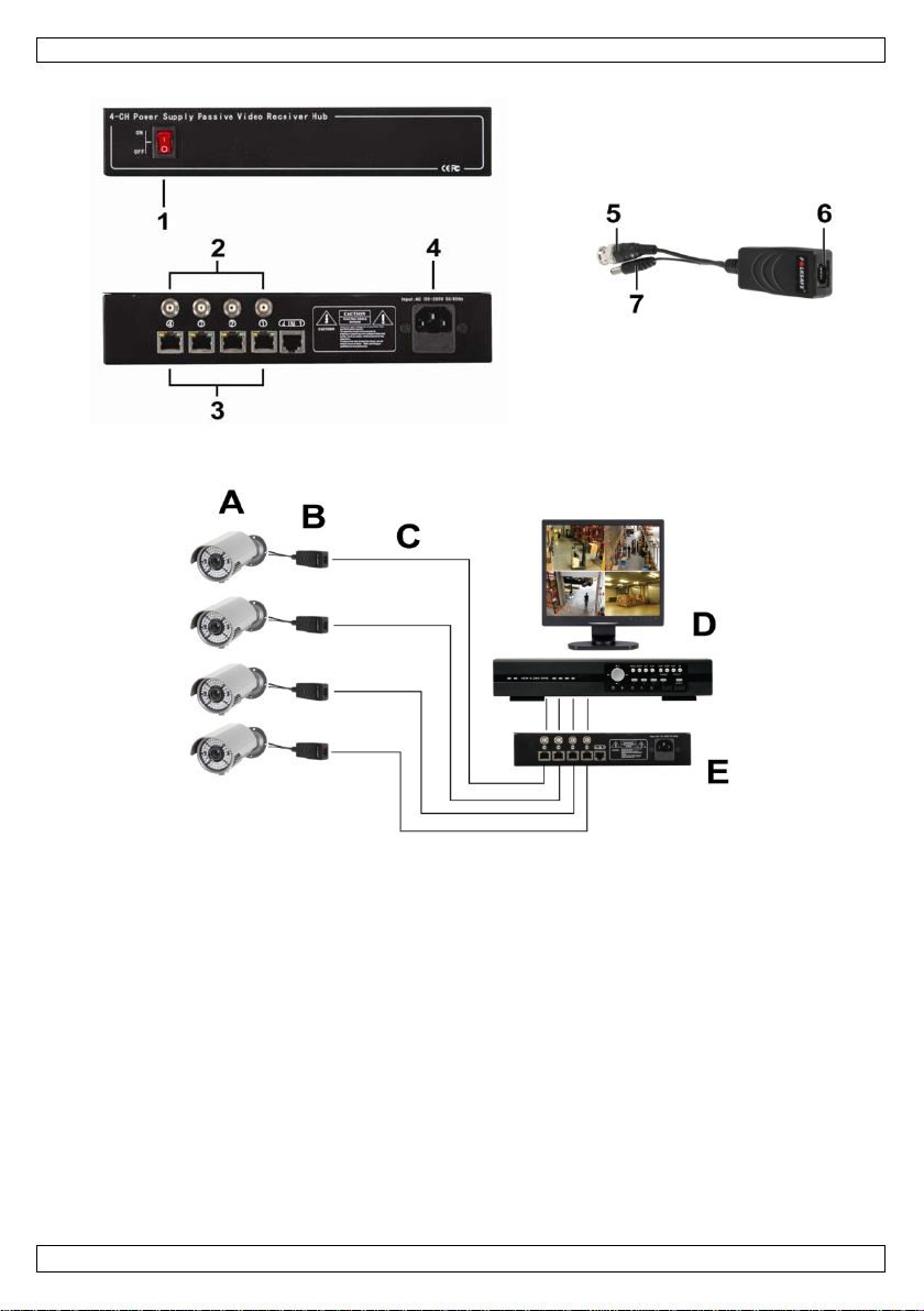
5. Overview
Refer to the illustrations on page 2 of this manual.
Receiver Balun
1 on/off switch 5 video connector for camera (BNC)
2 video output to DVR or monitor (BNC) 6 UTP cable connector
3 video inputs from camera (UTP cable) 7 power connector for camera
4 power supply connector
Connection scheme
A CCTV camera (not included) D DVR / monitor (not included)
B balun E CV045 receiver
C UTP cable (CAT5E/6, not included)
6. Hardware installation
Refer to the illustrations on page 2 of this manual.
You can connect up to 4 cameras to the receiver.
1. Connect the balun’s video connector [5] to the video connector of the camera [A].
2. Connect the balun’s power connector [7] to the power connector of the camera [A].
3. Connect the baluns [B] to the receiver [E] using CAT5E/6 cables [C].
Note: you can use either T568A or T568B cables (see wiring scheme further in this manual). Make
sure that both ends use the same wiring.
Note: the maximum cable length is 250m. For voltage drops over long distances, refer to the table
further in this manual.
4. Connect the receiver’s video output [2] of each camera to a monitor or DVR [D] using coax cables.
Use one cable per connected camera.
5. Plug the receiver’s power cord into the power supply connector [4].
6. Plug the power cord into a suitable mains socket (see Technical Specifications).
7. Switch on the rece iver using the on/off switch [1].
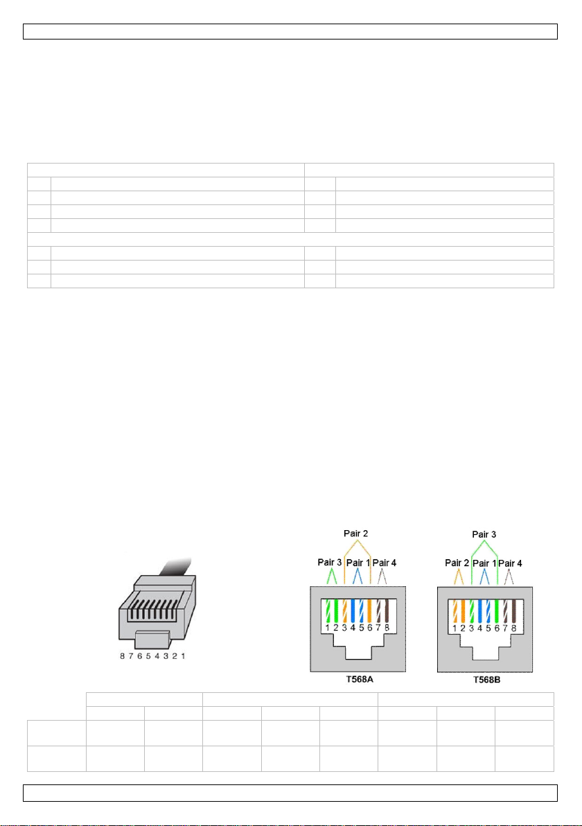
Wiring scheme
Video Power – Power +
1 2 3 4 5 6 7 8
T568A
T568B
white
green
white
orange
green
orange
white
orange
white
green
blue white blue orange
blue white blue green
white
brown
white
brown
brown
brown
V. 01 – 25/05/2012 4 ©Velleman nv
Page 5

CV045
Voltage drop according to cable length (24AWG)
Transmission distance
Transmission voltage
(12VDC, 0.5A)
Transmission voltage
(12VDC, 1.0A)
Transmission voltage
(12VDC, 1.5A)
50 m / 160 ft 13.5 V 15.5 V 17.0 V
100 m / 320 ft 15.5 V 18.5 V 22.0 V
150 m / 500 ft 17.0 V 22.0 V 27.0 V
200 m / 650 ft 18.5 V 25.5 V 32.0 V
300 m / 1000 ft 22.0 V 32.0 V 42.0 V
7. Technical Specifications
camera connector video BNC male / push-pin ter m in al
monitor/DVR connector video BNC male / push-pin termina l
video impedance BNC 75 ohms unbalanced
maximum cable length 250m
operating temperature -20°C ~ 70°C
power supply 230VAC / 50Hz
dimensions 4-channe l balun receiver w ith power
weight 4-channel balu n r ec e iver with power
Use this device with original accessories only. Velleman nv cannot be held responsible in the
event of damage or injury resulted from (incorrect) use of this device.
For more info concerning this product and the latest version of this manual, please visit our
website www.velleman.eu.
The information in this manual is subject to change without prior notice.
© COPYRIGHT NOTICE
The copyright to this manual is owned by Velleman nv. All worldwide rights reserved.
No part of this manual may be copied, reproduced, translated or reduced to any electronic medium or
otherwise without the prior written consent of the copyright holder.
power supply male 2.1mm DC plug
power supply 12V/5A power supply built-in
UTP (2 push-pins terminal block) 100 ohms balanced
250 x 170 x 45mm
supply built-in
passive video and power baluns 61 x 29 x 21mm
1600g
supply built-in
passive video and power baluns 40g
V. 01 – 25/05/2012 5 ©Velleman nv
Page 6

2
I
e
e
v
e
V
A
e
v
u
r
a
a
a
a
E
t
s
r
C
b
v
f
e
t
e
p
n
i
u
a
e
T
g
o
r
r
n
o
e
n
g
e
e
r
e
k
p
i
r
t
c
a
U
v
e
e
n
a
t
e
e
o
h
n
d
e
n
o
t
e
n
n
n
n
4
A
o
k
e
s
s
d
n
h
e
e
r
m
e
b
r
s
e
o
g
e
p
r
o
D
a
m
o
e
e
e
o
a
d
m
v
d
n
v
r
d
a
k
e
r
T
k
e
e
e
n
k
l
v
o
d
d
c
n
v
d
i
r
e
m
n
r
r
e
e
n
g
s
CV0
5
1.
Aan all
Belangr
verwijd
Dank u
toestel b
2.
3.
Raadple
nleiding
ingezetenen
ijke milieu-in
Dit symbool o
weggeworpen
batterijen) ni
terechtkomen
recyclagepun
Hebt u vrag
ring.
oor uw aankoo
schadigd tijde
eiligheids
Houd
Gebr
opsp
toest
rek
reini
Dem
onde
lgemene
g de Vellema
Besch
verst
ander
GEBR
an de Europ
ormatie betr
p het toestel of
, dit toestel sch
t bij het gewo
voor recyclage
brengen. Resp
n, contacteer
! Lees deze h
s het transpor
nstructies
buiten het ber
ik het toestel
ttende vloeist
l.
de stekker uit
t en als u het
nteer of open
delen in dit to
ichtlijnen
® service- e
erm tegen stof
pt geraken. Vo
object.
IKERSH
se Unie
ffende dit pr
de verpakking
ade kan toebre
e huishoudelij
. U moet dit to
ecteer de plaat
dan de plaat
ndleiding gr o n
, installeer het
ik van kindere
nkel binnens
ffen. Plaats ge
et stopcontact
iet gebruikt.
it toestel NOO
stel. Voor ond
kwaliteitsga
en extreme te
orzie een ruimt
NDLEI
duct
geeft aan dat,
ngen aan het
e afval; het m
stel naar uw v
elijke milieuw
elijke autorit
ig voor u het t
dan niet en ra
en onbevoeg
uis. Bescher
n objecten ge
(trek niet aan
IT. Er zijn gee
rhoud of reser
antie achteraa
peraturen. Zo
van minstens
ING
ls het na zijn l
ilieu. Gooi dit t
et bij een gesp
rdeler of naar
tgeving.
iten betreffe
estel in gebrui
dpleeg uw dea
en.
tegen regen,
uld met vloeist
e kabel!) voor
door de gebru
eonderdelen, c
n deze handlei
g dat de verlu
2,5 cm tussen
venscyclus wo
oestel (en eve
cialiseerd bed
en lokaal
d de
neemt. Werd
er.
ochtigheid en
f op of naast h
at u het toeste
iker vervangba
ontacteer uw d
ing.
htingsopeninge
het toestel en
rdt
tuele
ijf
het
et
l
e
aler.
n niet
lk
erm tegen sch
Besch
Leer
eerst de functi
Om
eiligheidsrede
gebr
iker heeft aan
Geb
uik het toestel
De g
rantie geldt ni
uw d
ealer zal de ve
nd mee houde
verb
Bew
ar deze handl
Inst
lleer en gebrui
igenscha
bied
de mogelijkhe
coax
kabel
uiter
t geschikt voo
lage
e installatiekos
8P8
(RJ45) conne
inge
ouwde oversp
5/05/2012
s van het toes
en mag u geen
ebracht valt ni
nkel waarvoor
t voor schade
antwoordelijkh
n.
iding voor verd
dit apparaat
pen
d een videosig
beveiliging- e
en door het ge
tor
nningbeveiligi
•
•
•
•
•
•
4.
•
•
•
•
•
V. 01 –
kken. Vermijd
el kennen voor
wijzigingen aa
et onder de ga
het gemaakt i
door het neger
id afwijzen vo
ere raadplegin
iet voor illegal
aal over te dra
bewakingstoe
bruik van een
g (Transient V
rute kracht tij
u het gaat geb
nbrengen. Sch
antie.
. Bij onoordeel
n van bepaald
r defecten of p
.
praktijken en
gen via een CA
assingen over
endabele UTP-
ltage Suppress
6
ens de bedieni
ruiken.
de door wijzigi
undig gebruik
richtlijnen in
roblemen die h
especteer iede
5E/6 UTP-kab
lange afstand
abel
ors)
ng.
gen die de
ervalt de gara
eze handleidin
er rechtstreek
s privacy.
l in plaats van
©Velle
tie.
en
een
an nv
Page 7

CV045
• bliksembeveiliging
• geen extra voeding voor camera nodig
• inhoud:
o 4-kanaals balunontvanger met ingebouwde voed ing: 1 st.
o passieve video-/voedingsbalun: 4 st.
o montagebeugel voor rekmontage: 2 st.
o coaxkabel voor aansluiting met monitor/DVR: 4 st.
5. Omschrijving
Raadpleeg de afbeeldingen op pagina 2 van deze handleiding.
Ontvanger Balun
1 Aan/uit-schakelaar 5 Videoaansluiting voor camera (BNC)
2 Video-uitgang naar DVR of monitor (BNC) 6 UTP-kabelaansluiting
3 Camera video-uitgangen (UTP-kabel) 7 Voedingsaansluiting voor camera
4 Voedingsaansluiting
Aansluitschema
A CCTV-camera (niet meegeleverd) D DVR / monitor (niet meegeleverd)
B Balun E CV045 ontvanger
C UTP-kabel (CAT5E/6, niet meegeleverd)
6. Hardware-installatie
Raadpleeg de afbeeldingen op pagina 2 van deze handleiding.
U kunt tot 4 camera's aansluiten op de ontvanger.
1. Sluit de videoaansluiting van de balun [5] aan op de videoaansluiting van de camera [A].
2. Sluit de voedingsaansluiting van de balun [7] aan op de voedingsaansluiting van de camera [A].
3. Verbind de baluns [B] met de ontvanger [E] d.m.v. CAT5E/6-kabels [C].
4. Opmerking: U kunt T568A of T568B-kabels gebruiken (zie aansluitschema verderop in deze
handleiding). Zorg ervoor dat beide uiteinden dezelfde aansluiting gebruiken.
Opmerking: de maximum kabellengte is 250m. Voor spanningsverliezen over lange afstanden,
raadpleeg de tabel verderop in deze handleiding.
5. Sluit de video-uitgang van de ontvanger [2] van iedere camera aan op een monitor of DVR [D] via
coaxkabels. Gebruik één kabel per aangesloten camera.
6. Verbind de voedingskabel van de ontvanger met de voedingsaansluiting [4].
7. Steek de stekker van de voedingskabel in een geschikt stopcontact (zie Technische
Specificaties).
8. Schakel de ontvanger in met de aan/uit-schakelaar [1].
Aansluitschema
V. 01 – 25/05/2012 7 ©Velleman nv
Page 8

CV045
5
Video Voeding – Voeding+
1 2 3 4 5 6 7 8
T568A wit groen groen wit oranje blauw wit blauw oranje wit bruin bruin
T568B wit oranje oranje wit groen blauw wit blauw groen wit bruin bruin
Spanningsverlies afhankelijk van de kabellengte (24AWG)
Transmissieafstand
Transmissiespanning
(12VDC, 0.5A)
Transmissiespanning
(12VDC, 1.0A)
Transmissiespanning
(12VDC, 1.5A)
0 m / 160 ft 13.5 V 15.5 V 17.0 V
100 m / 320 ft 15.5 V 18.5 V 22.0 V
150 m / 500 ft 17.0 V 22.0 V 27.0 V
200 m / 650 ft 18.5 V 25.5 V 32.0 V
300 m / 1000 ft 22.0 V 32.0 V 42.0 V
7. Technische specificaties
camera-aansluiting video BNC mannelijk /push-pin connector
voeding mannelijke DC-stekker 2.1mm
monitor/DVR-aansluiting video BNC manne lijk /push-pin connector
video-impedantie BNC 75 Ohm (ongebalanceerd)
max. kabellengte 250m
Werktemperatuur -20°C ~ 70°C
voeding 230VAC / 50Hz
afmetingen 4-kanaals balunontvanger met
gewicht 4-kanaals balunontvanger met
Gebruik dit toestel enkel met originele accessoires. Velleman nv is niet aansprakelijk voor
schade of kwetsuren bij (verkeerd) gebruik van dit toestel.
Voor meer informatie over dit product en de laatste versie van deze handleiding, zie
www.velleman.eu.
De informatie in deze handleiding kan te allen tijde worden gewijzigd zonder voorafgaande
kennisgeving.
© AUTEURSRECHT
Velleman nv heeft het auteursrecht voor deze handleiding. Alle wereldwijde rechten
voorbehouden.
Het is niet toegestaan om deze handleiding of gedeelten ervan over te nemen, te kopiëren, te vertalen,
te bewerken en op te slaan op een elektronisch medium zond er voorafgaande schriftelijke toestemming
van de rechthebbende.
voeding 12V/5A (ingebouwd)
UTP (2 push-pin connectoren) 100 Ohm (gebalanceerd)
250 x 170 x 45mm
ingebouwde voeding
passieve video-/voedingsbalun 61 x 29 x 21mm
1600g
ingebouwde voeding
passieve video-/voedingsbalun 40g
V. 01 – 25/05/2012 8 ©Velleman nv
Page 9
2
I
i
o
d
u
l
u
C
D
e
a
e
a
c
a
C
m
u
n
e
e
o
i
i
u
p
q
a
e
c
d
e
e
p
a
a
A
s
g
e
g
s
g
e
n
p
n
’
i
d
J
s
O
n
e
t
e
a
g
é
o
u
u
i
e
n
h
e
u
e
U
d
r
p
v
u
r
t
4
s
u
n
m
é
e
t
a
u
â
e
p
g
p
e
a
e
b
e
b
I
c
n
t
i
o
n
v
s
n
o
n
e
’
v
n
e
d
f
e
p
p
e
p
o
d
u
o
s
d
c
V
d
a
s
c
m
v
p
e
i
e
e
é
l
u
5
t
n
N
TICE D
5
CV0
’EMPLO
1.
Aux rés
Des inf
En cas
Nous vo
l’apparei
revende
2.
3.
Se référ
ntroducti
dents de l'Un
rmations env
Ce symbole s
peut polluer l'
éventuelles)
l’appareil en
recyclage loc
l’environnem
e questions,
s remercions d
. Si l’appareil a
r.
onsignes
Gard
Utilis
des
Débr
débr
NE J
l’utili
irectives
r à la garanti
Proté
fente
entre
n
on européen
ronnemental
r l'appareil ou
environnement
armi les déche
uestion. Renvo
l. Il convient d
nt.
ontacter les
e votre achat !
été endomma
e sécurit
r hors de la p
r cet appareil
rojections d’ea
ncher l’appare
ncher l'apparei
MAIS désass
ateur. Comma
énérales
de service et
er contre la po
de ventilation
l’enregistreur e
e
s importante
l'emballage ind
. Ne pas jeter
s municipaux
yer les équipe
respecter la r
utorités local
Lire la présent
é pendant le tr
rtée des enfan
niquement à
. Ne jamais pl
l s’il n’est pas
l ; non pas le c
mbler ou ouvri
der des pièces
de qualité Ve
ussière. Protég
ne soient pas b
t tout autre obj
concernant
ique que l’élimi
n appareil élec
on sujets au tr
ents usagés à
glementation l
es pour élimi
notice attenti
ansport, ne pa
s et des perso
l'intérieur. Pr
cer d’objet co
tilisé ou pour l
ble.
r le boîtier. Il n
de rechange é
lleman® en fi
r contre la cha
loquées. Laisse
et.
e produit
ation d’un app
rique ou électr
sélectif ; une
votre fournisse
cale relative à
ation.
ement avant la
l’installer et c
nes non autori
téger de la plu
tenant un liqui
nettoyer. Tire
y a aucune piè
entuelles chez
de notice.
leur extrême.
r une distance
areil en fin de
nique (et des
échèterie trait
r ou à un serv
la protection d
mise en servic
nsulter votre
ées.
ie, de l’humidit
e sur l’apparei
r la fiche pour
e maintenable
votre revende
eiller à ce que
e minimum 2,
ie
iles
ra
ce de
de
et
.
par
.
les
cm
•
•
•
•
•
•
4.
•
•
•
•
•
•
V. 01 –
Se f
miliariser avec
Tout
modification
modi
fications par le
N’uti
liser qu’à sa fo
La g
rantie ne s’ap
noti
e et votre reve
résul
tent.
Gard
er cette notice
Inst
ller et utiliser l
aractérist
per
et la transmiss
conç
pour des appl
dimi
uez les coûts
conn
ecteur 8P8C (R
prot
ction contre le
prot
ction contre la
5/05/2012
le fonctionnem
st interdite po
client ne tomb
ction prévue.
lique pas aux
deur déclinera
pour toute réfé
appareil en res
ques
ion d'un signal
ications de séc
'installation pa
45)
surtensions in
foudre
er contre les c
Proté
ocs et le traite
nt avant l’em
r des raisons d
nt pas sous la
n usage impro
ommages surv
toute respons
ence ultérieur
ectant la législ
idéo via un câ
rité et de surv
l'usage du câ
égrée (Transie
r avec circonsp
loi.
e sécurité. Les
arantie.
re annule d'of
nus en néglig
bilité pour les
.
ation et la vie
le UTP CAT5e/
illance sur un
le UTP économ
nt Voltage Sup
9
ction pendant
ommages occ
ice la garantie.
ant certaines d
roblèmes et le
rivée des tiers.
6 au lieu d'un
longue distanc
ique
ressors)
l’opération.
sionnés par de
irectives de cet
défauts qui e
âble coaxial
e
©Velle
s
e
an nv
Page 10

CV045
• ne nécessite pas de source d'alimentation supplémentaire pour caméra
• contenu :
o récepteur balun à 4 canaux avec alimentation incorporée : 1 pc
o balun vidéo/alimentation passif : 4 pcs
o étrier de montage pour montage en baie : 2 pcs
o câble coaxial pour connexion au mon iteur/DVR : 4 pcs.
5. Description
Se référer aux illustrations en page 2 de cette notice.
Récepteur Balun
1 Interrupteur marche/arrêt 5 Connecteur de vidéo pour caméra (BNC)
2 Sortie vidéo pour DVR ou moniteur (BNC) 6 Connecteur de câble UTP
3 Entrées vidéo de la caméra (câble UTP) 7 Connexion d'alimentation pour caméra
4 Connexion d'alimentation
Schéma de connexion
A Caméra CCTV (non incl.) D DVR / moniteur (non incl.)
B Balun E CV045
C Câble UTP (CAT5E/6, non incl.)
6. Installation du matériel
Se référer aux illustrations en page 2 de cette notice.
Il est possible de connecter jusqu'à 4 caméras au récepteur.
1. Connectez le connecteur de vidéo du balun [5] au connecteur de vidéo de la caméra [A].
2. Connectez la connexion d'alimentation du balun [7] à la connexion d'alimentation de la caméra [A].
3. Raccordez les baluns [B] au récepteur [E] avec des câbles CAT5E/6 [C].
Remarque : Vous pouvez utiliser des câbles T568A ou T568B (consultez le schéma de connexion ci-
après dans ce manuel). Assurez-vous que les deux extrémités utilisent la même connexion.
Remarque : la longueur maximale est de 250m. Pour des chutes de tension sur de longues
distances, veuillez consulter la table ci-après dans ce manuel.
4. Connectez la sortie vidéo du récepteur [2] de chaque camera au moniteur ou DVR [D] avec des
câbles coaxiaux. Utilisez un câble par caméra connectée.
5. Connectez le cordon d'alimentation du récepteur à la conn exion d'alimentation [4].
6. Branchez la fiche du cordon d'alimentation dans une prise de courant appropriée (voir
Spécifications Techniques).
7. Allumez le récepteur avec l'interrupteur marche/arrêt [1].
Schéma de connexion
V. 01 – 25/05/2012 10 ©Velleman nv
Page 11

CV045
Vidéo Alimentation – Alimentation +
1 2 3 4 5 6 7 8
T568A blanc vert vert
T568B
Chute de tension selon la longueur du câble (24AWG)
blanc
orange
orange blanc vert bleu blanc bleu vert
Distance de
transmission
blanc
orange
Tension de
transmission
(12VCC, 0.5A)
bleu blanc bleu orange
Tension de
transmission
(12VCC, 1.0A)
blanc
brun
blanc
brun
brun
Brun
Tension de
transmission
(12VCC, 1.5A)
50 m / 160 ft 13.5 V 15.5 V 17.0 V
100 m / 320 ft 15.5 V 18.5 V 22.0 V
150 m / 500 ft 17.0 V 22.0 V 27.0 V
200 m / 650 ft 18.5 V 25.5 V 32.0 V
300 m / 1000 ft 22.0 V 32.0 V 42.0 V
7. Spécifications techniques
connecteur de caméra vidéo BNC mâle/bornier à pression
alimentation connecteur DC mâle de 2.1mm
connecteur
moniteur/DVR
impédance vidéo BNC 75 Ohm (déséquilibré)
longueur max. du câble 250m
température de travail -20°C ~ 70°C
alimentation 230VCA / 50Hz
dimensions récepteur balun à 4 canaux avec
poids récepteur balun à 4 canaux avec
N’employer cet appareil qu’avec des accessoires d’origine. SA Velleman ne sera aucunement
responsable de dommages ou lésions survenus à un usage (incorrect) de cet appareil.
Pour plus d’information concernant cet article et la dernière version de cette notice, visiter
notre site web www.velleman.eu.
Toutes les informations présentées dans cette notice peuvent être modifiées sans notification
préalable.
© DROITS D’AUTEUR
SA Velleman est l’ayant droit des droits d’auteur pour cette notice. Tous droits mondiaux
réservés.
Toute reproduction, traduction, copie ou diffusion, intégrale ou partielle, du contenu de cette notice par
quelque procédé ou sur tout support électronique que se so it est in t er d ite sans l’accord préala b le écrit de
l’ayant droit.
vidéo BNC mâle/bornier à pression
alimentation 12V/5A (incorporée)
UTP (2 borniers à pression) 100 Ohm (équilibré)
250 x 170 x 45mm
alimentation incorporée
balun vidéo/alimentation passif 61 x 29 x 21mm
1600g
alimentation incorporée
balun vidéo/alimentation passif 40g
V. 01 – 25/05/2012 11 ©Velleman nv
Page 12

2
I
u
a
d
I
N
r
a
c
n
o
n
r
a
C
m
ñ
x
e
e
ó
a
c
a
e
p
n
e
e
ú
o
s
r
C
n
n
e
ú
n
u
t
r
l
p
i
a
s
5
i
s
N
e
e
o
p
c
e
5
e
u
o
l
c
T
o
s
E
o
f
t
c
s
e
r
c
d
ó
e
4
L
e
e
v
r
o
c
e
o
E
d
®
n
a
s
n
u
s
a
n
s
ó
b
e
o
R
e
r
m
p
n
u
u
d
e
e
é
e
a
o
u
e
o
.
a
a
c
s
o
s
o
e
c
q
a
r
d
s
r
y
r
o
n
s
c
d
m
r
m
n
n
a
n
a
CV0
5
1.
A los ci
Import
¡Gracias
Si el apa
distribui
2.
3.
Véase la
ntroducci
dadanos de l
ntes informa
Este símbolo
dañar el med
No tire este
empresa esp
reciclaje local
Si tiene dud
por haber com
rato ha sufrido
or.
nstruccio
Mant
Utilic
ning
Desc
ante
del p
NUN
de ni
ormas ge
Garantía de s
No ex
Aseg
de mí
MA
n
Unión Europ
iones sobre
en este aparat
io ambiente.
parato (ni las
cializada en re
. Respete las l
as, contacte c
rado el CV04
algún daño en
es de seg
nga el aparat
el aparato só
n tipo de salpi
necte siempre
de limpiarlo.
opio cable.
A desmonte n
guna pieza. C
erales
rvicio y calid
ponga este equ
rese de que lo
. 2,5cm entre
UAL DE
a
l medio ambi
o el embalaje
ilas, si las hubi
iclaje. Devuel
yes locales en
on las autorid
! Lea atentame
l transporte n
ridad
lejos del alcan
o en interior
adura o goteo.
el aparato si n
ire siempre del
i abra la caja.
ntacte con su
ad Velleman
ipo a polvo. No
orificios de ve
el aparato y cu
USUA
nte concerni
indica que, s i ti
ra) en la basu
a este aparato
elación con el
ades locales
nte las instrucc
lo instale y pó
e de personas
s. No exponga
Nunca ponga
va a usarlo d
enchufe para
l usuario no ha
istribuidor si n
al final de est
exponga este
tilación no est
lquier otro obj
IO
nte a este pr
ra las muestra
a doméstica; d
a su distribuid
edio ambient
ara residuos.
iones del manu
gase en conta
no capacitadas
este equipo a ll
n objeto con lí
rante un largo
esconectar el c
brá de efectua
cesita piezas
e manual del u
quipo a tempe
n bloqueados.
to.
ducto
inservibles, po
ebe ir a una
r o a la unidad
.
al antes de usa
to con su
y niños.
uvia, humedad
uido en el apa
período de tie
ble de red, nu
el mantenimie
e recambio.
uario.
aturas extrem
Deje una dista
drían
de
rlo.
ni a
ato.
po o
ca
to
s.
cia
•
•
•
•
•
•
4.
•
•
•
•
•
V. 01 –
Fami
liarícese con el
Por
azones de seg
caus
dos por modifi
Utili
e sólo el apara
gara
tía completam
Dañ
s causados po
gara
tía y su distrib
Gua
de este manua
Inst
le y utilice el a
aracteríst
per
ite la transmisi
dise
ado para aplic
dism
inuye los gasto
cone
ión 8P8C (RJ4
supr
sores de trans
prot
cción contra la
5/05/2012
funcionamient
ridad, las modi
caciones no au
o para las apli
ente.
descuido de la
uidor no será r
del usuario pa
arato al respe
cas
ón de señales
ciones de segu
de instalación
)
torios de tensi
sobretension
ite el aparato.
No ag
vite usar exce
del aparato a
icaciones no a
orizadas, no e
aciones descrit
instrucciones
sponsable de
a cuando nece
tar la legislaci
e vídeo por ca
ridad y vigilanc
gracias al cabl
n (Transient V
s
12
iva fuerza dur
tes de utilizarl
torizadas del a
tán cubiertos p
s en este man
de seguridad d
ingún daño u
ite consultarlo
n y la vida priv
le CAT5E/6 en
ia de larga dist
UTP económi
ltage Suppres
nte el manejo
.
parato están p
or la garantía.
al. Su uso inc
este manual i
tros problemas
da de tercero
lugar de cable
ncia
o
ors) incorpora
la instalación.
ohibidas. Los d
rrecto anula la
validarán su
resultantes.
.
oaxial
os para la
©Velle
ños
an nv
Page 13

CV045
• protección contra descargas atmosféricas
• no necesita una alimentación adicional para cámaras
• incluye:
o receptor balun de 4 canales con alimentación incorporada: 1 ud.
o balun vídeo/alimentación pasivo: 4 uds.
o soporte para montaje en rack: 2 uds.
o cable coaxial para la conexión a un monitor/DVR: 4 uds.
5. Descripción
Véase las figuras en la página 2 de este manual del usuario.
Receptor Balun
1 interruptor ON/OFF 5 conector de vídeo para cámara (BNC)
2 salida de vídeo para DVR o monitor (BNC) 6 conector para cable UTP
3 entradas de vídeo para cámara (cable UTP) 7 conector de alimentación para cámara
4 conexión de alimentación
Esquema de conexión
A cámara CCTV (no incl.) D DVR / monitor (no incl.)
B balun E receptor CV045
C cable UTP (CAT5E/6, no incl.)
6. Instalar el hardware
Véase las figuras en la página 2 de este manual del usuario.
Es posible conectar hasta 4 cámaras al receptor.
1. Conecte el conector de vídeo del balun [5] al conector de vídeo de la cámara [A].
2. Conecte el conector de alimentación del balun [7] al conector de alimentación de la cámara [A].
3. Conecte los balunes [B] al receptor [E] con los cables CAT5E/6 [C].
Observación: es posible utilizar o cables T568A o cables T568B (véase « esquema de conexión »
más adelante en este manual del usuario). Asegúrese de que ambos extremos utilizan los mismos
cables.
Observación: La longitud de l cable máx. es de 250m. Para caídas de tensión a largas distancias,
consulte la lista más adelante en este manual del usuario.
4. Conecte la salida de vídeo del receptor [2] de cada cámara a un monitor o un DVR [D] con cables
coaxiales. Utilice un cable por cámara conectada.
5. Conecte el cable de alimentación del receptor a la conexión de alimentación [4].
6. Conecte el aparato a la red eléctrica (véase Especificaciones).
7. Active el receptor con el interruptor ON/OFF [1].
Esquema de conexión
V. 01 – 25/05/2012 13 ©Velleman nv
Page 14

CV045
Vídeo Alimentación – Alimentación +
1 2 3 4 5 6 7 8
T568A
T568B
Caída de tensión según la longitud del cable (24AWG)
blanco
verde
blanco
naranja
verde
naranja
Distancia de
transmisión
blanco
naranja
blanco
verde
Tensión de
transmisión
(12VDC, 0.5A)
azul
azul
blanco
azul
blanco
azul
Tensión de
transmisión
(12VDC, 1.0A)
naranja
verde
blanco
marrón
blanco
marrón
marrón
marrón
Tensión de
transmisión
(12VDC, 1.5A)
50 m / 160 ft 13.5 V 15.5 V 17.0 V
100 m / 320 ft 15.5 V 18.5 V 22.0 V
150 m / 500 ft 17.0 V 22.0 V 27.0 V
200 m / 650 ft 18.5 V 25.5 V 32.0 V
300 m / 1000 ft 22.0 V 32.0 V 42.0 V
7. Especificaciones
conexión de cámara vídeo BNC macho / borne de conexión push-pin
alimentación conector DC macho de 2.1mm
monitor/conector DVR vídeo BNC macho / borne de conexión push-pin
alimentación 12V/5A (incorporada)
impedancia vídeo BNC 75 ohm no balanceado
longitud máx. del cable 250m
temperatura de
funcionamiento
alimentación 230VAC / 50Hz
dimensiones receptor balun de 4 canales con
peso receptor balun de 4 canales con
Utilice este aparato sólo con los accesorios originales. Velleman NV no será responsable de
daños ni lesiones causados por un uso (indebido) de este aparato.
Para más información sobre este producto y la versión más reciente de este manual del
usuario, visite nuestra página www.velleman.eu.
Se pueden modificar las especificaciones y el contenido de este manual sin previo aviso.
© DERECHOS DE AUTOR
Velleman NV dispone de los derechos de autor para este manual del usuario. Todos los
derechos mundiales reservados.
Está estrictamente prohibido reproducir, traducir, copiar, editar y guardar este manual del usuario o
partes de ello sin previo permiso escrito del derecho habiente.
UTP (borne de conexión con
100 ohm balanceado
2 push-pins)
-20°C ~ 70°C
250 x 170 x 45mm
alimentación incorporada
balun vídeo/alimentación pasivo 61 x 29 x 21mm
1600g
alimentación incorporada
balun vídeo/alimentación pasivo 40g
V. 01 – 25/05/2012 14 ©Velleman nv
Page 15
2
E
E
e
w
g
S
A
e
m
e
n
n
w
S
a
a
m
E
u
e
r
r
o
c
v
B
e
e
n
e
n
e
F T
n
a
o
e
v
z
e
h
e
e
r
e
G
e
F
w
t
r
E
n
e
u
n
a
e
a
e
0
a
n
n
G
r
e
f
n
i
r
h
.
ü
G
e
n
f
t
e
s
e
a
4
u
m
a
e
o
l
o
.
o
n
F
e
a
S
u
r
s
n
e
n
s
r
A
e
g
U
z
m
e
o
n
n
t
S
l
b
h
s
i
z
e
o
e
e
v
m
m
k
t
w
K
E
E
y
n
ö
r
s
a
g
t
e
r
G
e
e
s
d
e
e
m
s
i
d
m
n
g
ä
s
u
m
t
s
r
n
CV0
5
1.
An alle
Wichtig
Falls Z
Wir beda
sorgfälti
das Gerä
2.
3.
Siehe V
•
Neh
hab
•
Eige
eige
•
Ver
kann
•
Bei
Gara
•
Bew
•
Inst
Inti
4.
•
erla
•
eign
•
verri
inführung
inwohner de
Umweltinfo
Dieses Symb
Produktes na
Einheit (oder
verwendeten
werden. Dies
retourniert w
eifel bestehe
nken uns für d
durch. Überpr
t nicht und we
icherheits
Halte
Verw
und
ren
Sie d
Dem
Best
llgemeine
lleman® Ser
Schüt
Temp
Beac
ander
Verm
und B
en Sie das Ge
n.
mächtige Verä
mächtige Änd
enden Sie das
dies zu Schäd
chäden, die du
ntieanspruch.
hren Sie diese
llieren und ver
sphäre aller.
igenschaf
bt die Übertrag
t sich für weit
ngert die Instal
BEDI
Europäische
mationen üb
l auf dem Prod
h seinem Lebe
erwendeten B
atterien müss
Einheit muss
rden. Respekti
, wenden Sie
n Kauf des CV
üfen Sie, ob Tr
den Sie sich a
hinweise
n Sie Kinder u
nden Sie das
euchte. Stellen
en Sie das Ge
zu den Netzst
ntieren oder ö
llen Sie eventu
Richtlinie
ice- und Qual
en Sie das Ge
raturen. Beac
ten Sie eine mi
n Gegenstand
iden Sie Ersch
edienung des
ät erst in Betri
nderungen sind
rungen erlischt
erät nur für A
n am Produkt
rch Nichtbeach
ür daraus resul
Bedienungsanl
enden Sie das
en
ung von Video
eichende Sich
lationskoste n d
NUNGS
Union
r dieses Prod
kt oder der Ve
szyklus der U
tterien) nicht
n von einer sp
n den Händler
ren Sie die ört
sich für Ents
45! Lesen Sie
nsportschäden
Ihren Händler
d Unbefugte v
erät nur im I
Sie keine mit
ät bei Nichtben
cker an der Gr
fnen Sie das G
elle Ersatzteile
tätsgarantie
ät vor Staub.
ten Sie, dass d
nimale Entfern
tterungen. Ve
erätes.
b, nachdem Si
aus Sicherheit
der Garantiea
wendungen b
ühren und erlis
ung der Bedie
tierende Folge
itung für künft
Gerät nicht fü
ignalen über C
rheits- und Üb
nk des kosten
ANLEIT
kt
rpackung zeigt
welt Schaden
ls unsortiertes
zialisierten Fir
der ein örtlich
ichen Umweltv
rgungsrichtli
diese Bedienu
vorliegen. Soll
m Gerät fern.
nenbereich.
lüssigkeit befü
utzung und vor
ifffläche an und
rät NIE. Es gi
bei Ihrem Fach
m Ende dieser
chützen Sie da
ie Lüftungsschl
ng von 2.5cm
meiden Sie roh
e sich mit sein
gründen verb
spruch.
schrieben in di
cht der Garanti
ungsanleitung
chäden überni
ige Einsichtnah
illegale Prakti
T5E/6-Kabel s
rwachungsan
ünstigen UTP-
NG
an, dass die En
ufügen kann.
Hausmüll; die
a zwecks Rec
s Recycling-U
rschriften.
ien an Ihre
gsanleitung vo
e dies der Fall
chützen Sie d
lten Gegenstän
jeder Reinigun
ziehen Sie nie
t keine zu war
ändler.
Bedienungsanl
Gerät vor ext
tze nicht blocki
wischen dem
e Gewalt währ
n Funktionen v
ten. Bei Schäd
ser Bedienung
anspruch.
erursacht wer
mt der Herstel
e auf.
en und beacht
att Koaxialkab
endungen
abels
tsorgung diese
ntsorgen Sie d
inheit oder
cling entsorgt
ternehmen
rtliche Behör
Inbetriebnah
ein, verwende
s Gerät vor Re
de auf das Ger
vom Netz. Fa
an der Netzleit
enden Teile.
itung.
emen
ert werden.
erät und jede
nd der Installa
ertraut gemach
n verursacht d
anleitung son
en, erlischt de
ler keine Haftu
n Sie die
l
e
e.
e
Sie
en
t.
sen
ng.
ion
t
urch
t
g.
V. 01 –
5/05/2012
15
©Velle
an nv
Page 16

CV045
• 8P8C-Anschluss (RJ45)
• eingebaute Suppressordioden (Transient Voltage Suppressors) für Überspannungsschutz
• Blitzschutz
• braucht keine zusätzliche Stromversorgung für Kameras
• Lieferumfang:
o 4-Kanal Balunempfänger mit eingebauter Stromversorgung: 1 St.
o passives Video- und Strom-Balun: 4 St.
o Halterung für Rack-Montage: 2 St.
o Koaxialkabel für den Anschluss an einen Monitor/DVR: 4 St .
5. Umschreibung
Siehe Abbildungen, Seite 2 dieser Bedienungsanleitung.
Empfänger Balun
1 EIN/AUS-Schalter 5 Video-Anschluss für Kamera (BNC)
2 Video-Ausgang für DVR oder Monitor (BNC) 6 Anschluss für UTP-Kabel
3 Video-Eingänge für Kamera (UTP-Kabel) 7 Stromversorgungsstecker für Kamera
4 Anschluss für Stromversorgung
Schaltplan
A CCTV-Kamera (nicht mitgeliefert) D DVR / Monitor (nicht mitgeliefert)
B Balun E CV045-Empfanger
C UTP-Kabel (CAT5E/6, nicht mitgeliefert)
6. Installation der Hardware
Siehe Abbildungen, Seite 2 dieser Bedienungsanleitung.
Es können bis zu 4 Kameras an den Empfänger angeschlossen werden.
1. Verbinden Sie den Video-Anschluss des Baluns [5] m it dem Video-Anschluss der Kamera [A].
2. Stecken Sie den Stromversorgungsstecker des Baluns [7] in d en Stromversorgungsanschluss der
Kamera [A].
3. Verbinden Sie die Baluns [B] über CAT5E/6-Kabel [C] mit dem Empfänger [E].
Bemerkung: Verwenden Sie entweder T568A- oder T568B-Kabel (siehe « Schaltplan » weiter
hinten in dieser Anleitung). Beachten S ie, dass beide Enden dieselben Kabel verwenden.
Bemerkung: Die max. Kabellänge beträgt 250m. Siehe nachfolgende Liste für Spannungsabfälle
über große Entfernungen.
4. Verbinden Sie den Video-Ausgang des Empfängers [2] jeder Kamera über Koaxialkabel mit einem
Monitor oder DVR [D]. Verwenden Sie ein Kabel pro angeschlossene Kamera.
5. Verbinden Sie das Stromkabel des Empfängers mit dem Stromvers orgungsanschluss [4].
6. Verbinden Sie das Gerät mit dem Netz (siehe « Technische Daten »).
7. Schalten Sie den Empfänger mit dem EIN/AUS-Schalter [1] ein.
Schaltplan
V. 01 – 25/05/2012 16 ©Velleman nv
Page 17

CV045
Video Stromversorgung – Stromversorgung +
1 2 3 4 5 6 7 8
T568A
T568B
Spannungsabfall gemäß der Kabellänge (24AWG)
Übertragungs-
Reichweite
Weiß
Grün
Weiß
Orange
Grün
Orange
Übertragungsspannung
(12VDC, 0.5A)
Weiß
Orange
Weiß
Grün
Blau Weiß Blau Orange
Blau Weiß Blau Grün
Übertragungsspannung
Übertragungsspannung
(12VDC, 1.0A)
Weiß
Braun
Weiß
Braun
Braun
Braun
(12VDC, 1.5A)
50 m / 160 ft 13.5 V 15.5 V 17.0 V
100 m / 320 ft 15.5 V 18.5 V 22.0 V
150 m / 500 ft 17.0 V 22.0 V 27.0 V
200 m / 650 ft 18.5 V 25.5 V 32.0 V
300 m / 1000 ft 22.0 V 32.0 V 42.0 V
7. Technische Daten
Kamera-Anschluss Video BNC-Stecker / Push-Pin-Klemmleiste
Monitor/DVR-Anschluss Video BNC-Stecker / Push-Pin-Klemmleiste
Video-Impedanz BNC 75 Ohm unsymmetrisch
max. Kabellänge 250m
Betriebstemperatur -20°C ~ 70°C
Stromversorgung 230VAC / 50Hz
Abmessungen 4-Kanal Balunempfänger mit
Gewicht 4-Kanal Balunempfänger mit
Verwenden Sie dieses Gerät nur mit originellen Zubehörteilen. Velleman NV übernimmt keine
Haftung für Schaden oder Verletzungen bei (falscher) Anwendung dieses Gerätes.
Für mehr Informationen zu diesem Produkt und die neueste Version dieser
Bedienungsanleitung, siehe www.velleman.eu.
Alle Änderungen ohne vorherige Ankündigung vorbehalten.
© URHEBERRECHT
Velleman NV besitzt das Urheberrecht für diese Bedienungsanleitung. Alle weltweiten Rechte
vorbehalten.
Ohne vorherige schriftliche Genehmigung des Urhebers ist es nicht gestattet, diese Bedienungsanleitung
ganz oder in Teilen zu reproduzieren, zu kopieren, zu übersetzen, zu bearbeiten oder zu speichern.
Stromversorgung 2.1mm DC-Stecker
Stromversorgung 12V/5A (eingebaut)
UTP (Klemmleiste mit 2 Push-Pins) 100 Ohm symmetrisch
250 x 170 x 45mm
eingebauter Stromversorgung
passives Video- und Strom-Balun 61 x 29 x 21mm
1600g
eingebauter Stromversorgung
passives Video- und Strom-Balun 40g
V. 01 – 25/05/2012 17 ©Velleman nv
Page 18

Velleman® Service and Quality Warranty
Since its foundation in 1972, Velleman® acquired extensive experience in
the electronics world and currently distributes its products in over 85
countries.
All our products fulfil strict quality requirements and legal stipulations in
the EU. In order to ensure the quality, our products regularly go through
an extra quality check, both by an internal quality department and by
specialized external organisations. If, all precautionary measures
notwithstanding, problems should occur, please make appeal to our
warranty (see guarantee conditions).
General Warranty Conditions Concerning Consumer Products (for
EU):
• All consumer products are subject to a 24-month warranty on production
flaws and defective material as from the original date of purchase.
• Velleman® can decide to replace an article with an equivalent article, or
to refund the retail value totally or partially when the complaint is valid and
a free repair or replacement of the article is impossible, or if the expenses
are out of proportion.
You will be delivered a replacing article or a refund at the value of 100%
of the purchase price in case of a flaw occurred in the first year after the
date of purchase and delivery, or a replacing article at 50% of the
purchase price or a refund at the value of 50% of the retail value in case
of a flaw occurred in the second year after the date of purchase and
delivery.
• Not covered by warranty:
- all direct or indirect damage caused after delivery to the article (e.g. by
oxidation, shocks, falls, dust, dirt, humidity...), and by the article, as well
as its contents (e.g. data loss), compensation for loss of profits;
- consumable goods, parts or accessories that are subject to an aging
process during normal use, such as batteries (rechargeable, nonrechargeable, built-in or replaceable), lamps, rubber parts, drive belts...
(unlimited list);
- flaws resulting from fire, water damage, lightning, accident, natural
disaster, etc.…;
- flaws caused deliberately, negligently or resulting from improper
handling, negligent maintenance, abusive use or use contrary to the
manufacturer’s instructions;
- damage caused by a commercial, professional or collective use of the
article (the warranty validity will be reduced to six (6) months when the
article is used professionally);
- damage resulting from an inappropriate packing and shipping of the
article;
- all damage caused by modification, repair or alteration performed by a
third party without written permission by Velleman®.
• Articles to be repaired must be delivered to your Velleman® dealer,
solidly packed (preferably in the original packaging), and be completed
with the original receipt of purchase and a clear flaw description.
• Hint: In order to save on cost and time, please reread the manual and
check if the flaw is caused by obvious causes prior to presenting the
article for repair. Note that returning a non-defective article can also
involve handling costs.
• Repairs occurring after warranty expiration are subject to shipping costs.
• The above conditions are without prejudice to all commercial warranties.
The above enumeration is subject to modification according to the
article (see article’s manual).
Velleman® service- en kwaliteitsgarantie
Velleman® heeft sinds zijn oprichting in 1972 een ruime ervaring
opgebouwd in de elektronicawereld en verdeelt op dit moment producten
in meer dan 85 landen. Al onze producten beantwoorden aan strikte
kwaliteitseisen en aan de wettelijke bepalingen geldig in de EU. Om de
kwaliteit te waarborgen, ondergaan onze producten op regelmatige
tijdstippen een extra kwaliteitscontrole, zowel door onze eigen
kwaliteitsafdeling als door externe gespecialiseerde organisaties. Mocht
er ondanks deze voorzorgen toch een probleem optreden, dan kunt u
steeds een beroep doen op onze waarborg (zie waarborgvoorwaarden).
Algemene waarborgvoorwaarden consumentengoederen (voor
Europese Unie):
• Op alle consumentengoederen geldt een garantieperiode van 24
maanden op productie- en materiaalfouten en dit vanaf de oorspronkelijke
aankoopdatum.
• Indien de klacht gegrond is en een gratis reparatie of vervanging van
een artikel onmogelijk is of indien de kosten hiervoor buiten verhouding
zijn, kan Velleman® beslissen het desbetreffende artikel te vervangen
door een gelijkwaardig artikel of de aankoopsom van het artikel
gedeeltelijk of volledig terug te betalen. In dat geval krijgt u een
vervangend product of terugbetaling ter waarde van 100% van de
aankoopsom bij ontdekking van een gebrek tot één jaar na aankoop en
levering, of een vervangend product tegen 50% van de kostprijs of
terugbetaling van 50 % bij ontdekking na één jaar tot 2 jaar.
• Valt niet onder waarborg:
- alle rechtstreekse of onrechtstreekse schade na de levering veroorzaakt
aan het toestel (bv. door oxidatie, schokken, val, stof, vuil, vocht...), en
door het toestel, alsook zijn inhoud (bv. verlies van data), vergoeding voor
eventuele winstderving.
- verbruiksgoederen, onderdelen of hulpstukken die onderhevig zijn aan
veroudering door normaal gebruik zoals bv. batterijen (zowel oplaadbare
als niet-oplaadbare, ingebouwd of vervangbaar), lampen, rubberen
onderdelen, aandrijfriemen... (onbeperkte lijst).
- defecten ten gevolge van brand, waterschade, bliksem, ongevallen,
natuurrampen, enz.
- defecten veroorzaakt door opzet, nalatigheid of door een
onoordeelkundige behandeling, slecht onderhoud of abnormaal gebruik of
gebruik van het toestel strijdig met de voorschriften van de fabrikant.
- schade ten gevolge van een commercieel, professioneel of collectief
gebruik van het apparaat (bij professioneel gebruik wordt de
garantieperiode herleid tot 6 maand).
- schade veroorzaakt door onvoldoende bescherming bij transport van het
apparaat.
- alle schade door wijzigingen, reparaties of modificaties uitgevoerd door
derden zonder toestemming van Velleman®.
• Toestellen dienen ter reparatie aangeboden te worden bij uw
Velleman®-verdeler. Het toestel dient vergezeld te zijn van het
oorspronkelijke aankoopbewijs. Zorg voor een degelijke verpakking (bij
voorkeur de originele verpakking) en voeg een duidelijke foutomschrijving
bij.
• Tip: alvorens het toestel voor reparatie aan te bieden, kijk nog eens na
of er geen voor de hand liggende reden is waarom het toestel niet naar
behoren werkt (zie handleiding). Op deze wijze kunt u kosten en tijd
besparen. Denk eraan dat er ook voor niet-defecte toestellen een kost
voor controle aangerekend kan worden.
• Bij reparaties buiten de waarborgperiode zullen transportkosten
aangerekend worden.
• Elke commerciële garantie laat deze rechten onverminderd.
Bovenstaande opsomming kan eventueel aangepast worden
naargelang de aard van het product (zie handleiding van het
betreffende product).
Garantie de service et de qualité Velleman®
Depuis 1972, Velleman® a gagné une vaste expérience dans le secteur
de l’électronique et est actuellement distributeur dans plus de 85 pays.
Tous nos produits répondent à des exigences de qualité rigoureuses et à
des dispositions légales en vigueur dans l’UE. Afin de garantir la qualité,
nous soumettons régulièrement nos produits à des contrôles de qualité
supplémentaires, tant par notre propre service qualité que par un service
qualité externe. Dans le cas improbable d’un défaut malgré toutes les
précautions, il est possible d’invoquer notre garantie (voir les conditions
de garantie).
Conditions générales concernant la garantie sur les produits grand
public (pour l’UE) :
• tout produit grand public est garanti 24 mois contre tout vice de
production ou de matériaux à dater du jour d’acquisition effective ;
• si la plainte est justifiée et que la réparation ou le remplacement d’un
article est jugé impossible, ou lorsque les coûts s’avèrent
disproportionnés, Velleman® s’autorise à remplacer ledit article par un
article équivalent ou à rembourser la totalité ou une partie du prix d’achat.
Le cas échéant, il vous sera consenti un article de remplacement ou le
remboursement complet du prix d’achat lors d’un défaut dans un délai de
1 an après l’achat et la livraison, ou un article de remplacement
moyennant 50% du prix d’achat ou le remboursement de 50% du prix
d’achat lors d’un défaut après 1 à 2 ans.
• sont par conséquent exclus :
- tout dommage direct ou indirect survenu à l’article après livraison (p.ex.
dommage lié à l’oxydation, choc, chute, poussière, sable, impureté…) et
provoqué par l’appareil, ainsi que son contenu (p.ex. perte de données) et
une indemnisation éventuelle pour perte de revenus ;
- toute pièce ou accessoire nécessitant un remplacement causé par un
usage normal comme p.ex. piles (rechargeables comme non
rechargeables, intégrées ou remplaçables), ampoules, pièces en
caoutchouc, courroies… (liste illimitée) ;
- tout dommage qui résulte d’un incendie, de la foudre, d’un accident,
d’une catastrophe naturelle, etc. ;
Page 19

- out dommage provoqué par une négligence, volontaire ou non, une
utilisation ou un entretien incorrect, ou une utilisation de l’appareil
contraire aux prescriptions du fabricant ;
- tout dommage à cause d’une utilisation commerciale, professionnelle ou
collective de l’appareil (la période de garantie sera réduite à 6 mois lors
d’une utilisation professionnelle) ;
- tout dommage à l’appareil qui résulte d’une utilisation incorrecte ou
différente que celle pour laquelle il a été initialement prévu comme décrit
dans la notice ;
- tout dommage engendré par un retour de l’appareil emballé dans un
conditionnement non ou insuffisamment protégé.
- toute réparation ou modification effectuée par une tierce personne sans
l’autorisation explicite de SA Velleman® ; - frais de transport de et vers
Velleman® si l’appareil n’est plus couvert sous la garantie.
• toute réparation sera fournie par l’endroit de l’achat. L’appareil doit
nécessairement être accompagné du bon d’achat d’origine et être dûment
conditionné (de préférence dans l’emballage d’origine avec mention du
défaut) ;
• tuyau : il est conseillé de consulter la notice et de contrôler câbles, piles,
etc. avant de retourner l’appareil. Un appareil retourné jugé défectueux
qui s’avère en bon état de marche pourra faire l’objet d’une note de frais à
charge du consommateur ;
• une réparation effectuée en-dehors de la période de garantie fera l’objet
de frais de transport ;
• toute garantie commerciale ne porte pas atteinte aux conditions
susmentionnées.
La liste susmentionnée peut être sujette à une complémentation
selon le type de l’article et être mentionnée dans la notice d’emploi.
Garantía de servicio y calidad Velleman®
Desde su fundación en 1972 Velleman® ha adquirido una amplia
experiencia como distribuidor en el sector de la electrónica en más de 85
países. Todos nuestros productos responden a normas de calidad
rigurosas y disposiciones legales vigentes en la UE. Para garantizar la
calidad, sometemos nuestros productos regularmente a controles de
calidad adicionales, tanto a través de nuestro propio servicio de calidad
como de un servicio de calidad externo. En el caso improbable de que
surgieran problemas a pesar de todas las precauciones, es posible
recurrir a nuestra garantía (véase las condiciones de garantía).
Condiciones generales referentes a la garantía sobre productos de
venta al público (para la Unión Europea):
• Todos los productos de venta al público tienen un período de garantía
de 24 meses contra errores de producción o errores en materiales desde
la adquisición original;
• Si la queja está fundada y si la reparación o sustitución de un artículo no
es posible, o si los gastos son desproporcionados, Velleman® autoriza
reemplazar el artículo por un artículo equivalente o reembolsar la
totalidad o una parte del precio de compra. En este caso, usted recibirá
un artículo de recambio o el reembolso completo del precio de compra si
encuentra algún fallo hasta un año después de la compra y entrega, o un
artículo de recambio al 50% del precio de compra o el reembolso del 50%
del precio de compra si encuentra un fallo después de 1 año y hasta los 2
años después de la compra y entrega.
Por consiguiente, están excluidos entre otras cosas:
- todos los daños causados directa o indirectamente al aparato (p.ej. por
oxidación, choques, caída,...) y a su contenido (p.ej. pérdida de datos)
después de la entrega y causados por el aparato, y cualquier
indemnización por posible pérdida de ganancias;
- partes o accesorios, que estén expuestos al desgaste causado por un
uso normal, como por ejemplo baterías (tanto recargables como no
recargables, incorporadas o reemplazables), bombillas, partes de goma,
etc. (lista ilimitada);
- defectos causados por un incendio, daños causados por el agua, rayos,
accidentes, catástrofes naturales, etc.;
- defectos causados a conciencia, descuido o por malos tratos, un
mantenimiento inapropiado o un uso anormal del aparato contrario a las
instrucciones del fabricante;
- daños causados por un uso comercial, profesional o colectivo del
aparato (el período de garantía se reducirá a 6 meses con uso
profesional);
- daños causados por un uso incorrecto o un uso ajeno al que está
previsto el producto inicialmente como está descrito en el manual del
usuario;
- daños causados por una protección insuficiente al transportar el
aparato.
- daños causados por reparaciones o modificaciones efectuadas por una
tercera persona sin la autorización explícita de Velleman®;
- se calcula gastos de transporte de y a Velleman® si el aparato ya no
está cubierto por la garantía.
• Cualquier artículo que tenga que ser reparado tendrá que ser devuelto a
su distribuidor Velleman®. Devuelva el aparato con la factura de compra
original y transpórtelo en un embalaje sólido (preferentemente el
embalaje original). Incluya también una buena descripción del fallo;
• Consejo: Lea el manual del usuario y controle los cables, las pilas, etc.
antes de devolver el aparato. Si no se encuentra un defecto en el artículo
los gastos podrían correr a cargo del cliente;
• Los gastos de transporte correrán a carga del cliente para una
reparación efectuada fuera del período de garantía.
• Cualquier gesto comercial no disminuye estos derechos.
La lista previamente mencionada puede ser adaptada según el tipo
de artículo (véase el manual del usuario del artículo en cuestión).
Velleman® Service- und Qualitätsgarantie
Seit der Gründung in 1972 hat Velleman® sehr viel Erfahrung als Verteiler
in der Elektronikwelt in über 85 Ländern aufgebaut.
Alle Produkte entsprechen den strengen Qualitätsforderungen und
gesetzlichen Anforderungen in der EU. Um die Qualität zu gewährleisten
werden unsere Produkte regelmäßig einer zusätzlichen Qualitätskontrolle
unterworfen, sowohl von unserer eigenen Qualitätsabteilung als auch von
externen spezialisierten Organisationen. Sollten, trotz aller
Vorsichtsmaßnahmen, Probleme auftreten, nehmen Sie bitte die Garantie
in Anspruch (siehe Garantiebedingungen).
Allgemeine Garantiebedingunge n in Be zu g a uf Ko nsumgüter (für die
Europäische Union):
• Alle Produkte haben für Material- oder Herstellungsfehler eine
Garantieperiode von 24 Monaten ab Verkaufsdatum.
• Wenn die Klage berechtigt ist und falls eine kostenlose Reparatur oder
ein Austausch des Gerätes unmöglich ist, oder wenn die Kosten dafür
unverhältnismäßig sind, kann Velleman® sich darüber entscheiden,
dieses Produkt durch ein gleiches Produkt zu ersetzen oder die
Kaufsumme ganz oder teilweise zurückzuzahlen. In diesem Fall erhalten
Sie ein Ersatzprodukt oder eine Rückzahlung im Werte von 100% der
Kaufsumme im Falle eines Defektes bis zu 1 Jahr nach Kauf oder
Lieferung, oder Sie bekommen ein Ersatzprodukt im Werte von 50% der
Kaufsumme oder eine Rückzahlung im Werte von 50 % im Falle eines
Defektes im zweiten Jahr.
• Von der Garantie ausgeschlossen sind:
- alle direkten oder indirekten Schäden, die nach Lieferung am Gerät und
durch das Gerät verursacht werden (z.B. Oxidation, Stöße, Fall, Staub,
Schmutz, Feuchtigkeit, ...), sowie auch der Inhalt (z.B. Datenverlust),
Entschädigung für eventuellen Gewinnausfall.
- Verbrauchsgüter, Teile oder Zubehörteile, die durch normalen Gebrauch
dem Verschleiß ausgesetzt sind, wie z.B. Batterien (nicht nur aufladbare,
sondern auch nicht aufladbare, eingebaute oder ersetzbare), Lampen,
Gummiteile, Treibriemen, usw. (unbeschränkte Liste).
- Schäden verursacht durch Brandschaden, Wasserschaden, Blitz,
Unfälle, Naturkatastrophen, usw.
- Schäden verursacht durch absichtliche, nachlässige oder
unsachgemäße Anwendung, schlechte Wartung, zweckentfremdete
Anwendung oder Nichtbeachtung von Benutzerhinweisen in der
Bedienungsanleitung.
- Schäden infolge einer kommerziellen, professionellen oder kollektiven
Anwendung des Gerätes (bei gewerblicher Anwendung wird die
Garantieperiode auf 6 Monate zurückgeführt).
- Schäden verursacht durch eine unsachgemäße Verpackung und
unsachgemäßen Transport des Gerätes.
- alle Schäden verursacht durch unautorisierte Änderungen, Reparaturen
oder Modifikationen, die von einem Dritten ohne Erlaubnis von Velleman®
vorgenommen werden.
• Im Fall einer Reparatur, wenden Sie sich an Ihren Velleman®-Verteiler.
Legen Sie das Produkt ordnungsgemäß verpackt (vorzugsweise die
Originalverpackung) und mit dem Original-Kaufbeleg vor. Fügen Sie eine
deutliche Fehlerbeschreibung hinzu.
• Hinweis: Um Kosten und Zeit zu sparen, lesen Sie die
Bedienungsanleitung nochmals und überprüfen Sie, ob es keinen auf de
Hand liegenden Grund gibt, ehe Sie das Gerät zur Reparatur
zurückschicken. Stellt sich bei der Überprüfung des Gerätes heraus, dass
kein Geräteschaden vorliegt, könnte dem Kunden eine
Untersuchungspauschale berechnet.
• Für Reparaturen nach Ablauf der Garantiefrist werden Transportkosten
berechnet.
• Jede kommerzielle Garantie lässt diese Rechte unberührt.
Die oben stehende Aufzählung kann eventuell angepasst werden
gemäß der Art des Produktes (siehe Bedienungsanleitung des
Gerätes).
 Loading...