

Page 1
CTC1000
GSM BASED WIRELESS HOME ALARM SYSTEM
DRAADLOOS ALARMSYSTEEM MET GSM-MODULE
SYSTÈME D'ALARME SANS FIL AVEC MODULE GSM
SISTEMA DE ALARMA INALÁMBRICO CON MÓDULO GSM
DRAHTLOSE ALARMANLAGE MIT GSM-MODUL
SISTEMA DE ALARME SEM FIOS POR GSM PARA HABITAÇÃO
USER MANUAL 3
GEBRUIKERSHANDLEIDING 38
MODE D'EMPLOI 74
MANUAL DEL USUARIO 111
BEDIENUNGSANLEITUNG 147
MANUAL DO UTILIZADOR 183
Page 2
CTC1000
V. 01 – 12/06/2013 2 ©Velleman nv
Page 3
CTC1000
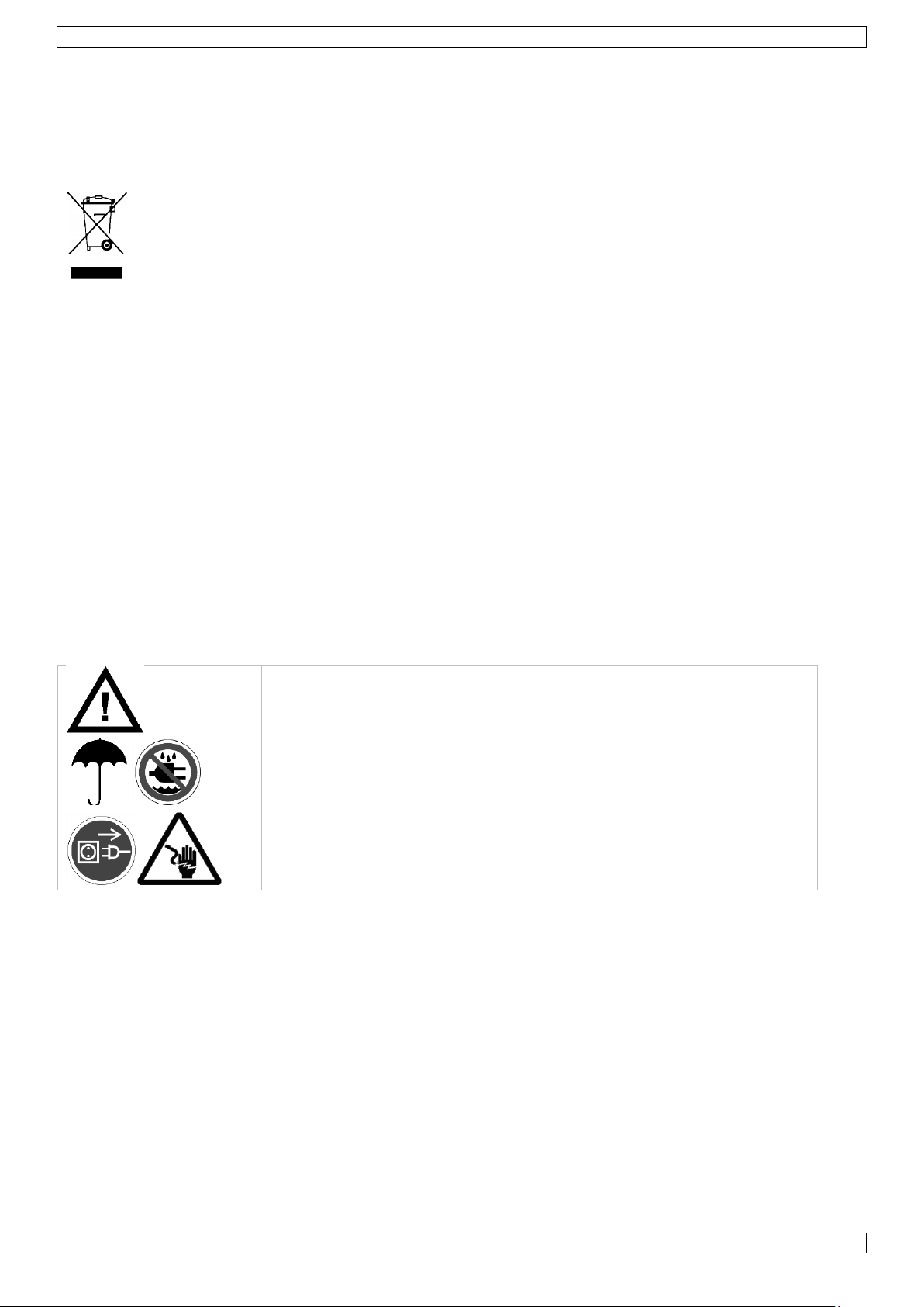
Keep the device away from children and unauthorised users.
Indoor use only.
Keep this device away from rain, moisture, splashing and dripping liquids.
Remove power before opening the cover. Be very careful, touching live
wires can cause life-threatening electroshocks.
USER MANUAL
1. Introduction
To all residents of the European Union
Important environmental information about this product
This symbol on the device or the package indicates that disposal of the device after its lifecycle could
harm the environment. Do not dispose of the unit (or batteries) as unsorted municipal waste; it
should be taken to a specialized company for recycling. This device should be returned to your
distributor or to a local recycling service. Respect the local environmental rules.
If in doubt, contact your local waste disposal authorities.
Thank you for choosing Velleman! Please read the manual thoroughly before bringing this device into service. If
the device was damaged in transit, don't install or use it and contact your dealer.
Package contents
Control panel
Power adapter
Ni-Mh rechargeable battery
Optional
PIR motion sensor (order code CTC1000PIR)
door contact (order code CTC1000DS)
remote keypad (order code CTC1000KP)
remote control (order code CTC1000RC)
water sensor (order code CTC1000WS)
external bell box (order code CTC1000SO)
wireless siren (order code CTC1000SI)
2. Safety Instructions
Damage caused by disregard of certain guidelines in this manual is not covered by the warranty and the
dealer will not accept responsibility for any ensuing defects or problems.
Keep the device away from splashing and dripping liquids.
Note that damage caused by user modifications to the device is not covered by the warranty.
This system can provide valuable protection for your home and property if used properly. However, it
cannot guarantee complete protection against burglary or robbery. Therefore, VELLEMAN nv will not be
responsible for any losses or damages which occur during the use of this product.
3. General Guidelines
Refer to the Velleman® Service and Quality Warranty on the last pages of this manual.
Have the system installed by a qualified installer.
Respect the legislation in your region when installing an alarm system. If necessary, refer to local
authorities.
Protect this device from shocks and abuse. Avoid brute force when operating the device.
Protected the device against extreme heat, dust and moisture.
V. 01 – 12/06/2013 3 ©Velleman nv
Page 4

CTC1000
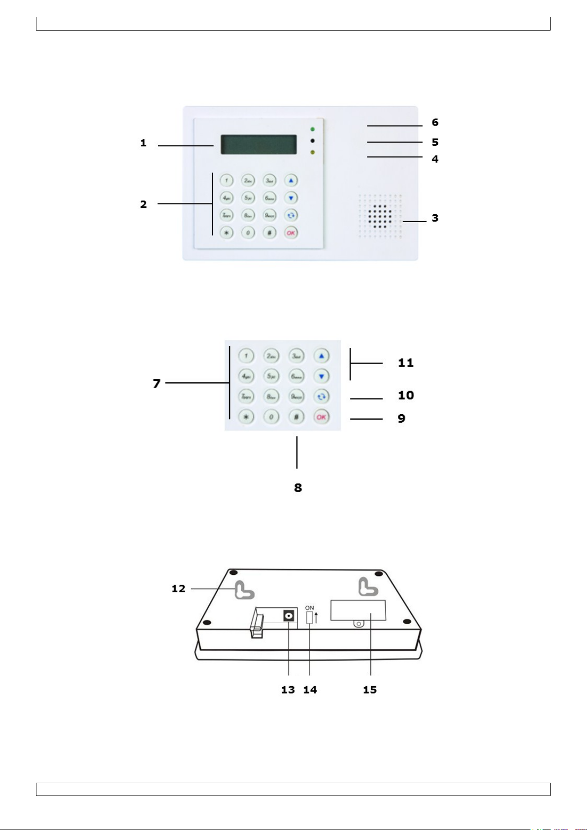
1
display
2
keypad
3
buzzer
4
yellow LED
- on: an error is detected
- off: no errors, the control panel is in normal mode
5
microphone
6
green LED
- on: AC power is on
- off: AC power failure
7
letters and digits
8
#: used to enter Program mode
9
OK: confirms data or selection
10
Cancel: used in Program mode: cancels a selection, returns to a previous screen...
11
up and down arrows: used in Program mode: moves the cursor up and down to select an item
12
2 mounting holes and tamper
13
DC jack
14
battery switch
15
SIM card compartment
Familiarise yourself with the functions of the device before actually using it.
All modifications of the device are forbidden for safety reasons.
The device does not contain any user-serviceable parts except for the battery.
Only use the device for its intended purpose. Using the device in an unauthorised way will void the
warranty.
4. Features
30-zone full featured wireless control panel with built-in GSM dialler
SMS messages
up to 6 different phone numbers can be pre-stored in the system and dialled to call for help, in order of
priority
1 recordable general message with a capacity of 10 seconds
4 fixed alarm messages for burglar, emergency, fire, and medical alarms
call acknowledgement by recipient ensures the calls are received
listen-in feature allows the call recipient to listen in to what is happening on your side
SMS editing: 14 characters x 4 lines = 56 characters in total
remote command and access to the system from anywhere via SMS
16 x 2 characters backlit full text LCD display
each of the 30 zones can be individually named/edited by the user for quick recognition of designated areas
built-in transmitter to activate outdoor bell box or wireless siren
"home" arming option offers full protection while you are at home, yet allows you to move freely inside
without triggering the alarm
full supervision to ensure problem-free operation
door open/close monitoring before system arming adds extra security
error detection and display
tamper detection protects the unit from unauthorized opening or removal from its mounting surface
5. Overview
Refer to the illustrations on page 2 of this manual.
V. 01 – 12/06/2013 4 ©Velleman nv
Page 5
CTC1000
WARNING
Do not puncture or throw batteries in fire as they might explode.
Keep batteries away from children.
6. Installation
6.1 SIM card (optional)
You can insert a SIM card in the control panel to send alarm reports to your mobile phone (up to six numbers).
Before you start
Before inserting the SIM card in the control panel and mounting it, it is recommended to test the country
code format used by your mobile phone provider. See section Country Code in chapter 10.
Use your phone to remove the pin code from the SIM card.
Inserting a SIM card
The SIM card holder is located at the back of the device.
To insert your SIM card:
1. Unscrew the SIM card compartment.
2. Slide the holder to the right to open it (see the OPEN mark on the holder).
3. Open the holder and insert your SIM card.
4. Slide the holder to the left to close it (see the CLOSE mark on the holder).
5. Close the compartment using the screw.
6.2 Power supply
Use the included AC power adapter to connect the control panel to a wall outlet.
Be sure only to use an adapter with the appropriate AC voltage rating to prevent component damage (see
Technical Specifications below for details).
Rechargeable battery
A rechargeable battery (included, see Technical Specifications below for details) inside the control panel
serves as a backup in case of power failure.
During normal operation, the AC power adapter is used to supply power to the control panel and at the
same time recharge the battery.
When the battery is fully charged, it can provide back-up power for at least 8 hours. It takes approximately
48 hours to fully charge the battery.
Backlit display
The device has a backlit LCD display for easy operation in the dark. However, when AC power is missing and for
the reason of conservation of rechargeable battery, Backlit feature will be disabled until the AC power is
supplied again.
6.3 Mounting the control panel
Find a suitable location: requirements
Take the following requirements into account when choosing a suitable location for the control panel.
The control panel requires mains power.
The control panel should be easily accessible.
Do not install the control panel in a damp place (bathroom...)
Do not install the control panel close to a heat source.
Do not install the control panel alongside other radio transmitting devices such as mobile phones, cordless
phone or wireless computer network (Wi-Fi) devices.
Mounting the control panel
The control panel can be mounted on the wall or wherever desired. Make sure the control panel is fitted at
approximately chest height where the display can be easily seen and the keypad convenient to operate.
1. Use the 2 holes of the wall bracket to mark off the holes‟ positions.
2. Drill 2 holes and insert the wall plugs if fixing into plaster or brick.
3. Screw the base to the wall
V. 01 – 12/06/2013 5 ©Velleman nv
Page 6
CTC1000
4. Insert the power supply in the power jack before attaching the panel to the wall.
5. Hook the control panel onto the wall bracket (holding the unit with the front facing you).
6.4 Two level passwords
In order to provide highest security in operating the system, the control panel has 2 levels of authorization.
When you want to program the system, you have to enter your pin code as well as a master code.
When the control panel asks you to key in ENTER CODE or P-CODE, please enter your user pin code.
When the display panel asks you to key in M-CODE, please enter your master code.
For details about the pin code, see section 7.4 Pin code.
For details about the master code, see section 7.7 Master Code.
6.5 First use
Assuming you have found a suitable location:
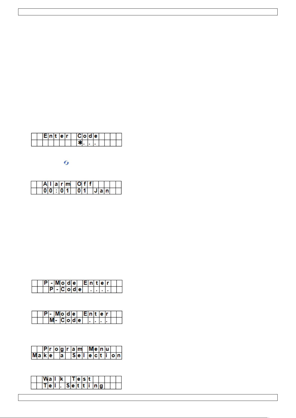
1. Apply the AC power to the control panel. You will hear a long beep. Alarm On will be displayed on the first
line and 00:01 01 Jan displayed on the second line of the screen indicating the system is in Away Mode
(this is the default Mode)
2. Press button 1 on the keypad.
3. Key in the pin code for user 1 (default code is 1234) within 30 seconds.
You can press to clear the code.
4. Press the OK key (within 30 seconds).
You will hear 2 short beeps and the display will show:
The system is now in alarm off mode.
5. Wait for 2 to 3 minutes for the system to read it status. If the yellow LED turns on, it indicates that there is
an error. Refer to section 14 for details.
Notes
The control panel has a screen saver function.
The Alarm off message will be displayed for 180 seconds. After that, the display shows only current date
and time.
7. Configuration
To enter Program mode:
1. Make sure the alarm is off (see section 11.4).
2. Press the # key. The display shows:
3. Within 30 seconds, key in 1234 (default User1 pin code) and press OK.
The display shows:
4. Within 30 seconds, enter 1111 (default Master Code) and press OK.
For 2 seconds, the display shows:
5. Then the program menu will be displayed:
V. 01 – 12/06/2013 6 ©Velleman nv
Page 7
CTC1000
It is highly recommended to change the User 1 pin code and the master code on first use.
Cursor
The cursor is indicated by a flashing dot in the left upper corner.
Use the keys and to move the cursor.
Press OK to confirm.
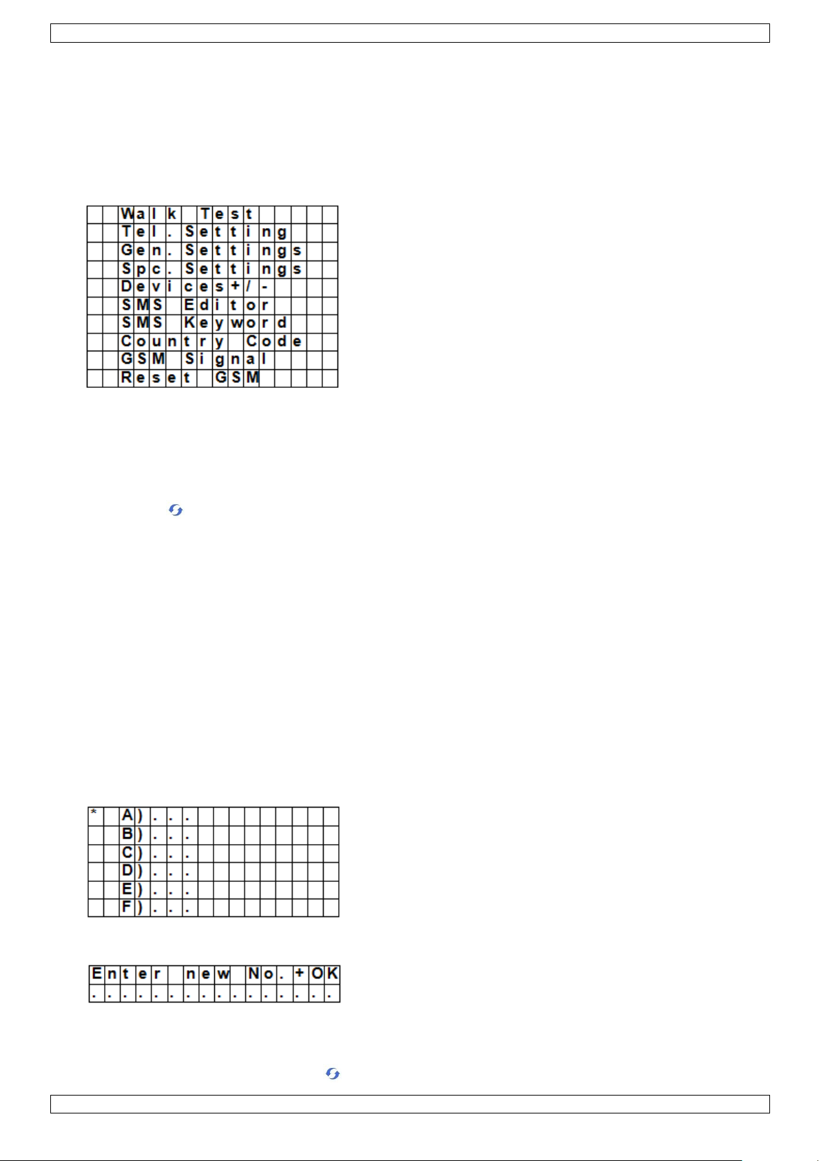
The Program menu contains the following items:
Notes
A down arrow V indicates that the list can be scrolled down. The arrow disappears when you reach the
bottom of the list.
An up arrow Λ indicates that the list can be scrolled up. The arrow disappears when you reach the top of
the list.
Press Cancel to return to the Alarm Off display.
In Program mode, if no key is pressed within 5 minutes, the control panel will automatically return to alarm
off mode.
7.2 Tel. Setting
In the Tel. Setting menu, you can add, change or delete the mobile phone numbers.
The control panel will use these numbers to report events.
You can add up to 6 numbers.
Notes
The display only shows the first 11 digits of a number.
The numbers are listed in order of priority. The system will connect to the phone numbers in that order. If
the control panel fails to connect to the first number, it will try the next one on the list.
To add a phone number
1. Enter Program mode and select Tel. Settings from the menu.
The display lists the phone numbers. This list is empty on first use.
2. Use the arrow keys to select the letter to which you want to assign a number (A to F) and press OK.
3. Key in the phone number and press OK.
o The number can contain up to 20 digits and characters * & #.
o When entering a number, the key acts as backspace.
V. 01 – 12/06/2013 7 ©Velleman nv
Page 8
CTC1000
Use
Required to arm and disarm the alarm system.
Required to access Program mode (together with the master code).
Default value
User 1: 1234
User 2 to 4: not set
Properties
4 digits
Mandatory
The code for user 1 cannot be deleted.
Will be reset to default when resetting the system (see chapter System reset)
The pin code needs to be different from the master code
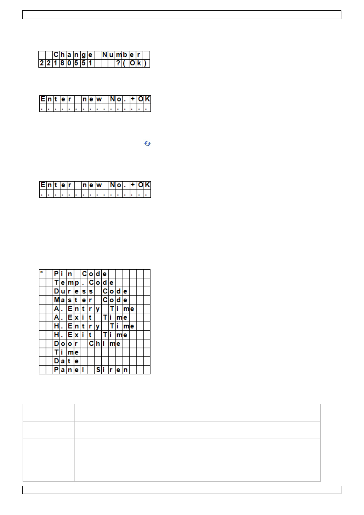
To change a phone number
1. Enter Program mode and select Tel. Settings from the menu.
The display lists the phone numbers.
2. Use the arrow keys to select the number you want to change and press OK.
This will clear the phone number.
3. Key in the phone number and press OK.
o The number can contain up to 20 digits and characters * & #.
o When entering a number, the key acts as backspace.
To delete a phone number
1. Enter Program mode and select Tel. Settings from the menu.
The display lists the phone numbers.
2. Use the arrow keys to select the number you want to delete and press OK.
3. Press OK again.
The number is deleted.
7.3 General settings
To access the menu item: enter Program mode and select Gen. Settings from the menu.
The menu items are
7.4 Pin code
V. 01 – 12/06/2013 8 ©Velleman nv
Page 9
CTC1000
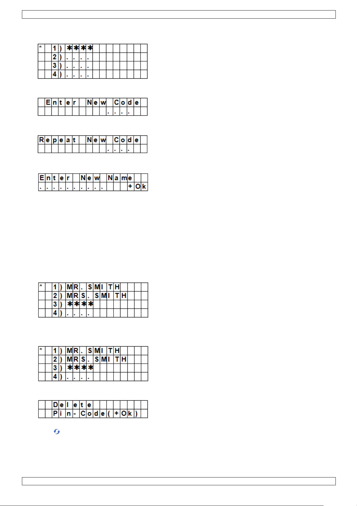
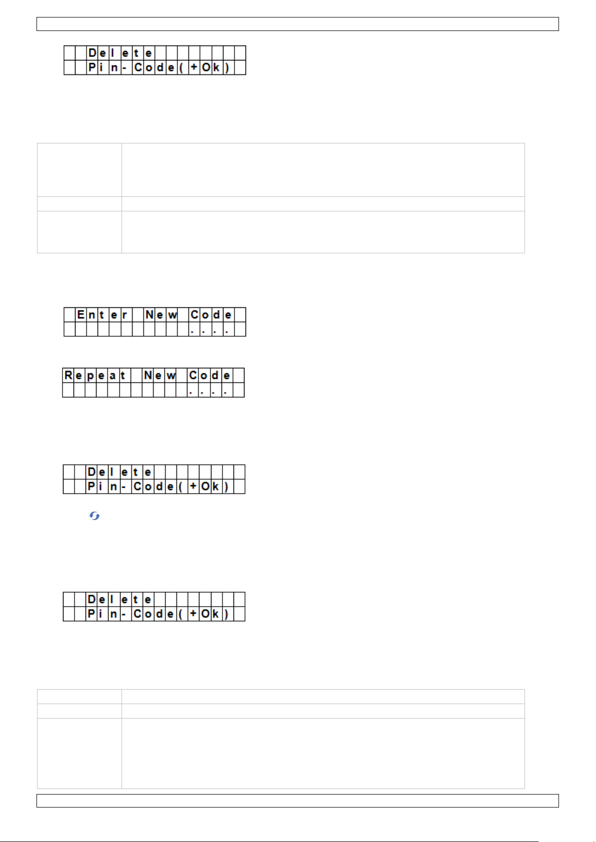
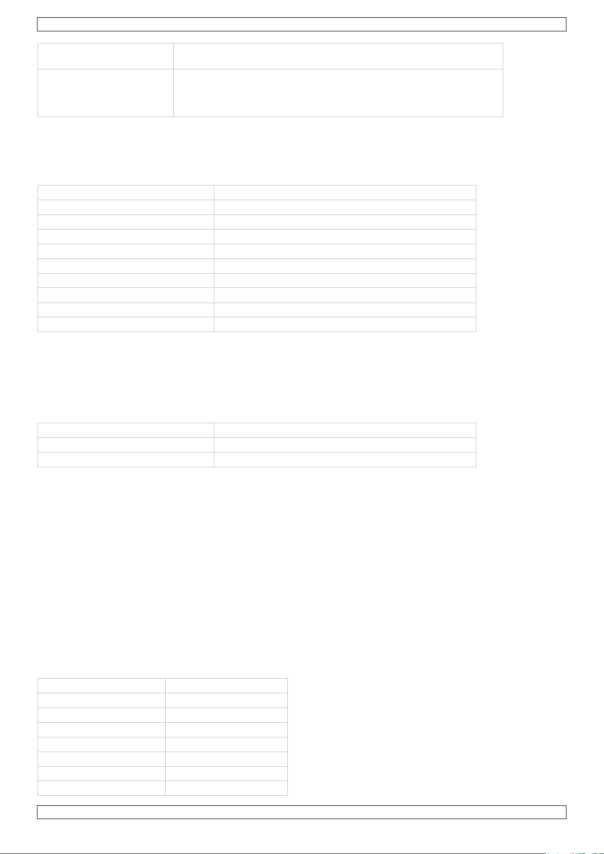
To set a pin code
1. To access the menu item: enter Program mode, go to Gen. Settings, select Pin code and press OK.
2. Use the arrow keys to select the code number you want to set and press OK.
3. Key in a 4 digit code and press OK.
4. Repeat the code and press OK.
5. (optional) Enter a name for the code.
o This name will be displayed in the list of pin codes and helps you identify the code.
o For information about entering text, see section 17 Entering text.
o If you do not want to use a name, leave this field blank.
6. Press OK.
Notes
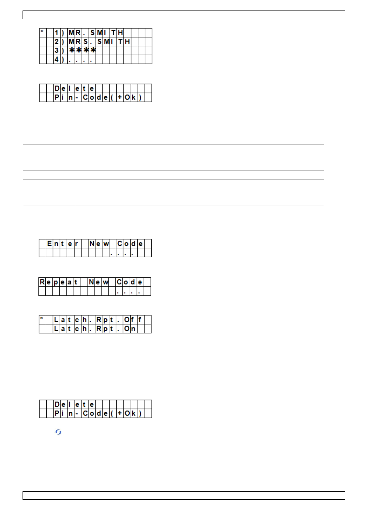
In the list of codes:
a pin code with no name will be displayed as ****
a pin code not yet defined will be displayed as ••••
To change a pin code
1. To access the menu item: enter Program mode, go to Gen. Settings, select Pin code and press OK.
2. Use the arrow keys to select the code you want to change and press OK.
3. Press .
4. Refer to topic To set a pin code above.
To delete a pin code
Pin code 1 cannot be deleted. To delete another code:
1. To access the menu item: enter Program mode, go to Gen. Settings, select Pin code and press OK.
V. 01 – 12/06/2013 9 ©Velleman nv
Page 10
CTC1000
Use
Used to arm or disarm the alarm system for a temporary user
Valid only once for turning the alarm on or off.
Once used, the code is automatically erased and needs to be reset if necessary
Default value
Not set
Properties
4 digits
Optional
Will be cleared when resetting the system (see chapter System reset)
2. Use the arrow keys to select the code you want to delete and press OK.
3. Press OK again.
7.5 Temp. Code
To set a temporary code
1. To access the menu item: enter Program mode, go to Gen. Settings, select Temp. Code and press OK.
2. Key in a 4 digit code and press OK.
3. Repeat the code and press OK.
4. Set the option Latch Rpt. (latch key reporting) to on or off.
o This option is only visible if the Latch Option is set to ON in the Special Settings.
See section Latch Option in chapter 8 Special Settings for detailed information.
5. Press OK.
To change a temporary code
1. To access the menu item: enter Program mode, go to Gen. Settings, select Temp. code and press OK.
2. Press .
3. Refer to topic To set a temporary code above.
To delete a temporary code
1. To access the menu item: enter Program mode, go to Gen. Settings, select Temp. code and press OK.
V. 01 – 12/06/2013 10 ©Velleman nv
Page 11
CTC1000
Use
Can be used to arm or disarm the alarm system.
Entering the code when under duress from an assailant triggers a silent alarm and
sends a secret message to the programmed mobile phones.
No siren will sound for duress alarm.
Default value
Not set
Properties
4 digits
Optional
Will be cleared when resetting the system (see chapter System reset)
Use
Required together with the pin code to enter the device‟s Program mode.
Default value
1111
Properties
4 digits
Mandatory
Cannot be deleted
Will be reset to default when resetting the system (see chapter System reset)
The master code needs to be different from the pin codes
2. Press OK again.
7.6 Duress Code
To set a duress code
1. To access the menu item: enter Program mode, go to Gen. Settings, select Duress Code and press OK.
2. Key in a 4 digit code and press OK.
3. Repeat the code and press OK.
To change a duress code
1. To access the menu item: enter Program mode, go to Gen. Settings, select Duress Code and press OK.
2. Press .
3. Key in a 4 digit code and press OK.
4. Repeat the code and press OK.
To delete a duress code
1. To access the menu item: enter Program mode, go to Gen. Settings, select Duress Code and press OK.
2. Press OK again.
7.7 Master Code
V. 01 – 12/06/2013 11 ©Velleman nv
Page 12
CTC1000
To set a master code
1. To access the menu item: enter Program mode, go to Gen. Settings, select Master Code and press OK.
2. Key in a 4 digit code and press OK.
3. Repeat the code and press OK.
To change a master code
1. To access the menu item: enter Program mode, go to Gen. Settings, select Master Code and press OK.
2. Press .
3. Key in a 4 digit code and press OK.
4. Repeat the code and press OK.
To delete a master code
1. To access the menu item: enter Program mode, go to Gen. Settings, select Master Code and press OK.
2. Press OK again.
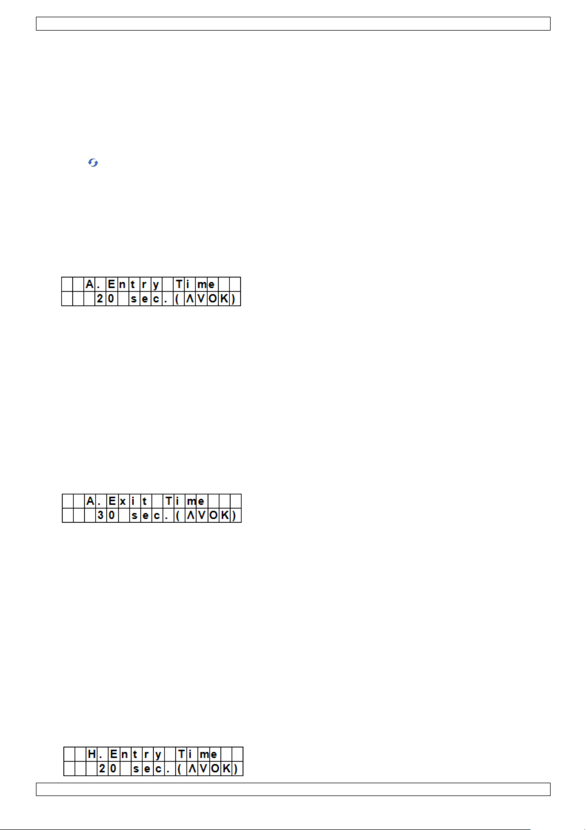
7.8 A. Entry Time
The option A. Entry Time (away entry time) sets the countdown time you have to provide a pin code after
entering the house.
Preconditions:
Alarm status: away
Detection devices involved: door contact or PIR sensor set as Entry or Away Entry (see section 9.3).
Action: the countdown starts when the door contact or PIR sensor is triggered.
If the pin code has not been given within the time set, the control panel will raise an alarm and send a
report.
Available timer options: Disable (alarm will be raised without any delay) and delays from 10 to 70 seconds.
Factory default is 20 seconds.
To access this menu item: enter Program mode, go to Gen. Settings, select A. Entry Time and press OK.
7.9 A. Exit Time
The option A. Exit Time (away exit time) sets the countdown time you have to leave the house when the alarm
has been set to away by the control panel, a remote control or a remote keypad.
Preconditions:
Alarm status: set to away by the control panel, a remote control or a remote keypad
Action: the countdown starts when the alarm is set to away by the control panel, a remote control or a
remote keypad.
Available timer options: Disable (no exit timer will be set) and delays from 10 to 70 seconds.
Factory default is 30 seconds.
To access this menu item: enter Program mode, go to Gen. Settings, select A. Exit Time and press OK.
Notes
Pressing the Arm button on the remote control will restart the countdown timer.
Pressing the Disarm button on the remote control will stop the counter and disarm the alarm.
Entering a pin code on the control panel will stop the counter and disarm the alarm.
7.10 H. Entry Time
V. 01 – 12/06/2013 12 ©Velleman nv
Page 13
CTC1000
The option H. Entry Time (home entry time) sets the countdown time you have to enter the house when the
system is set in Home mode.
Preconditions:
Alarm status: home mode
Detection devices involved: door contact or PIR sensor set as Entry or Home Access (see section 9.3).
Action: the countdown starts when the door contact or PIR sensor is triggered.
If the pin code has not been given within the time set, the control panel will raise an alarm and send a
report.
Available timer options: Disable (alarm will be raised without any delay) and delays from 10 to 70 seconds.
Factory default is 20 seconds.
To access this menu item: enter Program mode, go to Gen. Settings, select H. Entry Time and press OK.
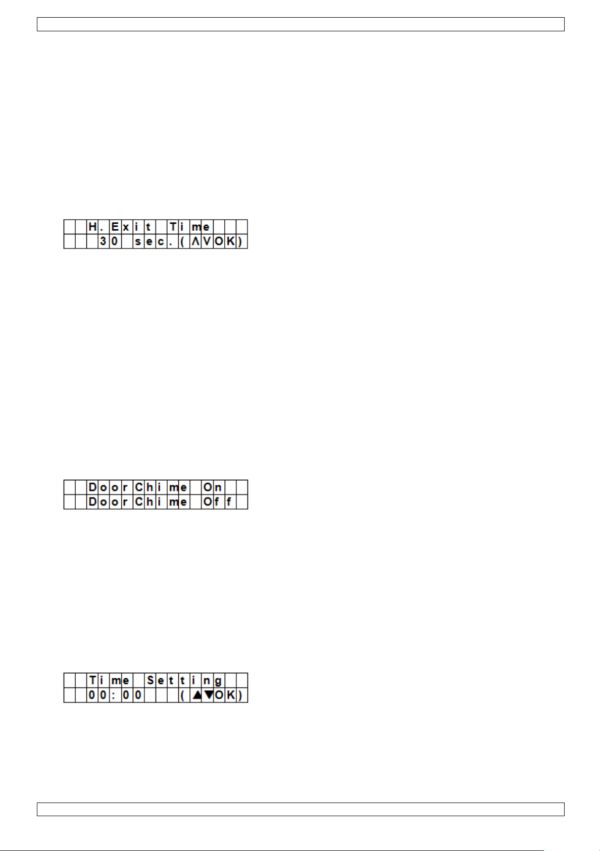
7.11 H. Exit Time
The option H. Exit Time (home exit time) sets the countdown time you have to leave the house when the
system is set in Home mode.
Preconditions:
Alarm status: set to away by the control panel, remote control or remote keypad
Action: the countdown starts when the alarm is set to away by the control panel, a remote control or a
remote keypad.
Available timer options: Disable (no exit timer will be set) and delays from 10 to 70 seconds.
Factory default is 30 seconds.
To access this menu item: enter Program mode, go to Gen. Settings, select H. Exit Time and press OK.
Notes
Pressing the Home button on the remote control will restart the countdown timer.
Pressing the Disarm button on the remote control will stop the counter and disarm the alarm.
Entering a pin code on the control panel will stop the counter and disarm the alarm.
7.12 Door Chime
The option Door Chime sets the door chime on or off while a door contact or PIR sensor is activated in alarm off
mode.
Preconditions:
Alarm status: off
Detection devices involved: door contact or PIR sensor set as Entry or Away Entry (see section 9.3).
Action: The control panel sounds a door chime while the door contact or PIR sensor is activated in alarm off
mode.
Factory default is off.
To access this menu item: enter Program mode, go to Gen. Settings, select Door Chime and press OK.
7.13 Time
The option Time allows setting the current time.
1. To access this menu item: enter Program mode, go to Gen. Settings, select Time and press OK.
2. Use the up and down arrows to set the hours and press OK.
3. Use the up and down arrows to set the minutes and press OK.
V. 01 – 12/06/2013 13 ©Velleman nv
Page 14
CTC1000
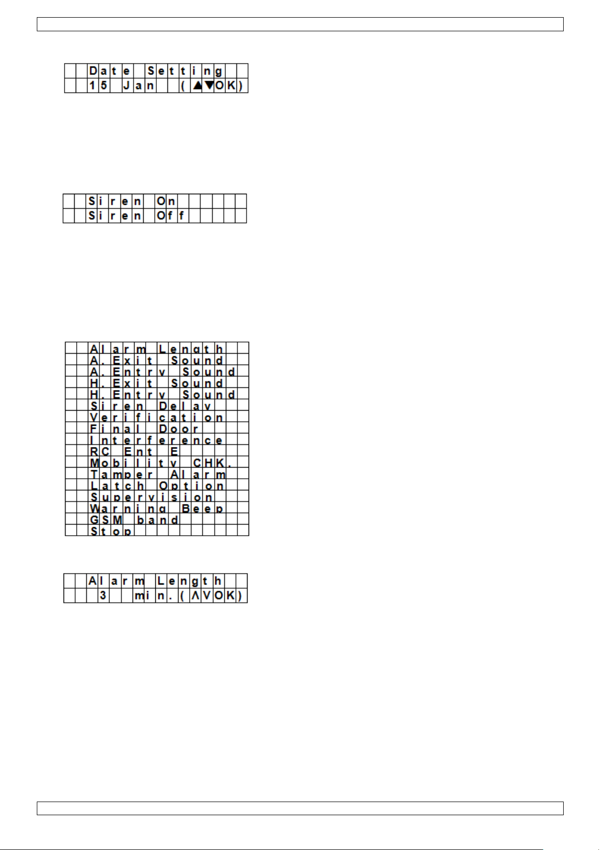
7.14 Date
The option Date allows setting the current date.
1. To access this menu item: enter Program mode, go to Gen. Settings, select Date and press OK.
2. Use the up and down arrows to set the month and press OK.
3. Use the up and down arrows to set the day and press OK.
7.15 Panel Siren
The option Panel Siren allows setting the siren on the control panel to on or off when an alarm event occurs.
1. To access this menu item: enter Program mode, go to Gen. Settings, select Panel Siren and press OK.
2. Use the up and down arrows to select the option and press OK.
8. Special Settings
To access the items from the Spc. Settings menu:
Enter Program mode and go to Spc. Settings.
Alarm Length
Sets the length of the built-in siren when an alarm is activated.
Available options are: Disable (no alarm will be set) and 1 to 15 minutes.
System default is 3 minutes.
Notes
If Disable is selected, when the control panel receives an alarm signal, the panel siren and internal &
external sirens will not raise an alarm sound.
If the outdoor siren alarm length is longer than the control panel‟s, the system gives priority to the control
panel. (for example when the siren‟s alarm length is set to 3 minutes and the panel‟s alarm length is set to
1 minute, both alarm siren stop at 1 minute; however, the outdoor siren‟s LED keeps flashing for 3
minutes.
V. 01 – 12/06/2013 14 ©Velleman nv
Page 15

CTC1000
A. Exit Sound
(=away exit sound)
Sets the countdown beeper sounds on or off for the away exit timer.
A. Entry Sound
(=away entry sound)
Sets the countdown beeper sounds on or off for the away entry timer.
H. Exit Sound
(=home exit sound)
Sets the beeper sounds on or off when leaving the house in Home mode.
H. Entry Sound
(=home entry sound)
Sets the beeper sounds on or off when entering the house in Home mode.
Siren Delay
Sets how long the control panel should delay or suppress audible signals for burglar or entry alarms.
Available options are: Off (no sound) and 1 to 10 minutes.
System default is set to off.
Notes
The Siren Delay option only applies to burglar or entry alarms. Other alarms will not be delayed:
o Fire alarm
o Water alarm
o Personal panic alarm
o Medical emergency
o Tamper alarm
o GSM failure
The alarm reporting will be sent immediately, even if the audible alarm is delayed.
V. 01 – 12/06/2013 15 ©Velleman nv
Page 16
CTC1000
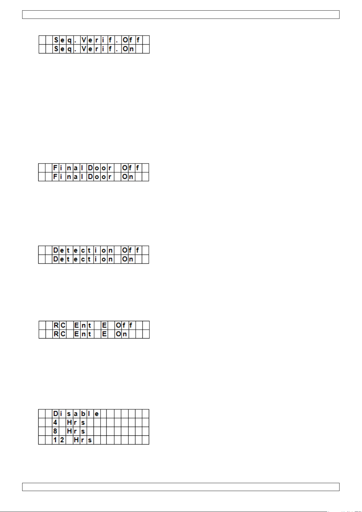
Verification
Sets the verification sequence for the alarms.
Sequential verification on
If sequential verification is set to On and
If there is more than one sensor (door contacts or PIR) with attribute set to Burglar:
o If the first sensor is triggered, the control panel will send an SMS with burglar.
o If the second sensor is triggered within 30 minutes, the control panel will send an SMS with Alarm
confirm.
Sequential verification off
If sequential verification is set to Off, the control panel will only send an SMS with Burglar.
Final Door
If the Final Door option is set to on and
If the alarm system is set to away arming and
a door contact is set as Entry device
The system will automatically full arm once the door contact is detected as closed, even if the countdown period
is not yet finished.
Interference
Allows setting whether the control panel should detect signal jamming or not.
When Detection is set to On, whenever the signal jamming period lasted longer than 30 seconds, this error
will be logged, reported to the Central Monitoring Station and displayed on the LCD to warn the user.
When the Detection Off is selected, control panel will not check interference status.
RC Ent E (= remote controller entry enabled)
This feature is used to prevent the alarm from being turned off with a remote control without unlocking a door
first, for example if the remote has been stolen.
To access the function:
you need to first activate and entry point device to be able to disarm the alarm system.
If the remote controller entry is set to On:
a remote control can disarm the alarm system without unlocking a door first.
Mobility
This option disables or enables the Mobility Timer and sets a countdown period. Options available are Disable, 4
hours, 8 hours and 12 hours.
If the Mobility Timer is enabled, it will count down the pre-programmed time length. When the timer times out
without being reset, a report will be made to the Programmed phone numbers.
V. 01 – 12/06/2013 16 ©Velleman nv
Page 17
CTC1000
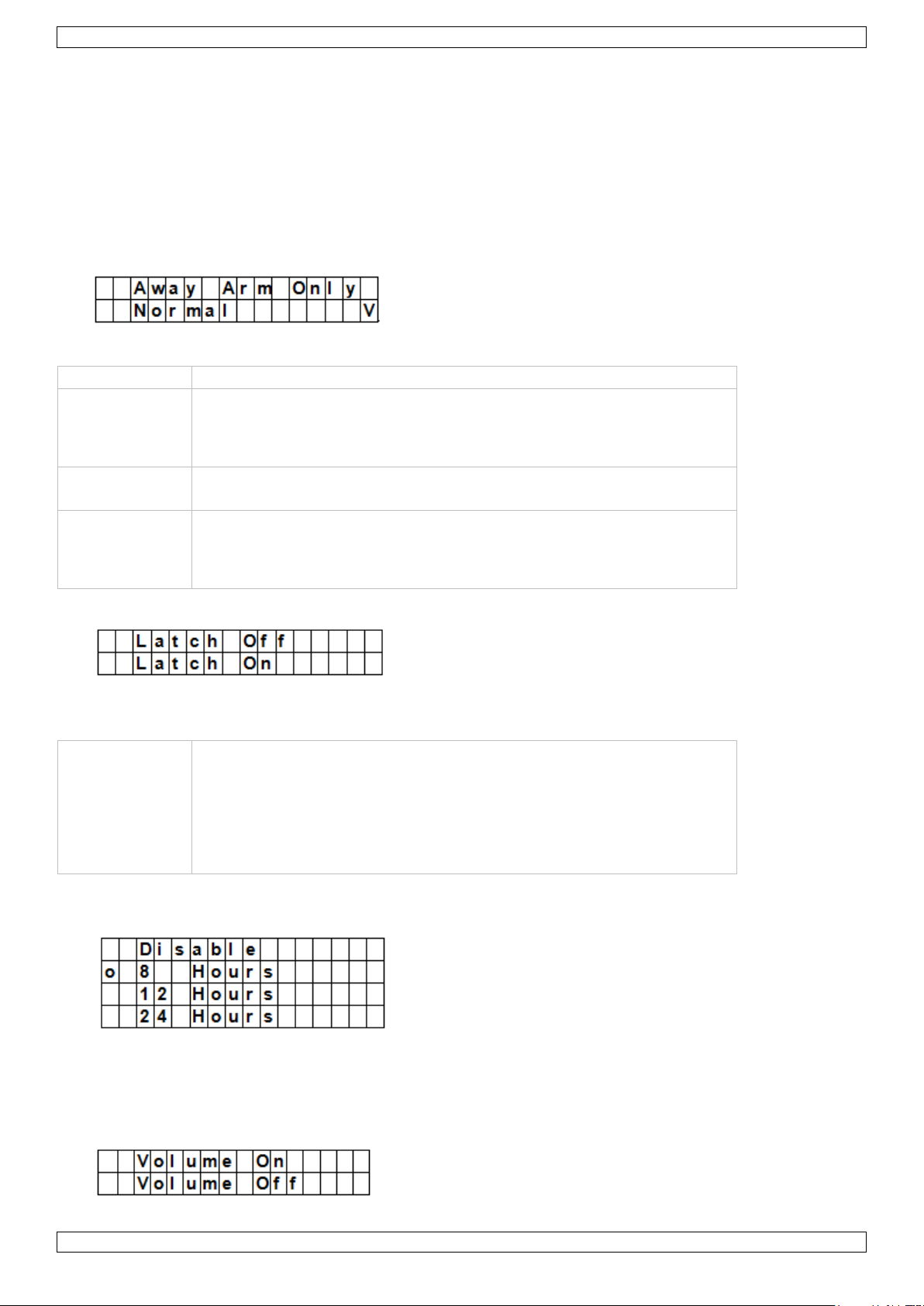
Option
Function
Away Arm Only
The control panel will only raise a local alarm and send a report to the
monitoring centre when in Away mode.
If the alarm is in Home or Alarm off modes, the control panel will send
a report but the siren will not sound.
Normal
The control panel will raise a local alarm and send a report to the
monitoring centre in all modes.
Notes
Regardless of the siren setting, the panel will report the tamper alarm
by SMS to the first telephone number in all modes.
When tamper is restored, the panel also will report the tamper restore
event by SMS to the first telephone number.
Notes
If the Latchkey Reporting feature is set to Off, the feature will be
hidden from the program menu (see section 7.5 Temp. Code).
If the Latchkey Reporting feature is set to On, all arming/disarming
actions of all users and the RCs will by default be reported to the
Central Monitoring Station.
For receiving the SMS-report, set the first telephone number as SMS
report.
When the Mobility timer is set with a specified timer, the control panel will report to the Programmed phone
numbers when the timer runs out unless one of the following actions occurred in advance to reset the
timer:
o In Home mode: whenever any Home Omit DC, IR is triggered, or whenever any of the keys of the
control panel is pressed;
o In Disarm mode: whenever any of the DC or IR (except 24 Hr, Fire, Medical Emergency and Water) is
triggered, or whenever any of the keys of the control panel is pressed.
When the system is set to Away Arm, the timer automatically stops. When the system enters Home Arm or
Disarm mode, the timer automatically starts again.
Tamper Alarm
Allows setting when the siren will sound when the system is being tampered with.
Latch Option
The Latch Option logs the arming/disarming actions from all users done on the control panel and remote
control.
Supervision
This option is used to enable system supervision function. When this option is set to ON, the control panel will
be able to receive check-in signals from its devices to indicate their proper functioning.
Options are: Disable, 8 Hours, 12Hours, and 24Hours.
Warning Beep
V. 01 – 12/06/2013 17 ©Velleman nv
Page 18
CTC1000
Sets the beep to on or off when the control panel displays an error message.
The warning beep will disappear when the error message has been read.
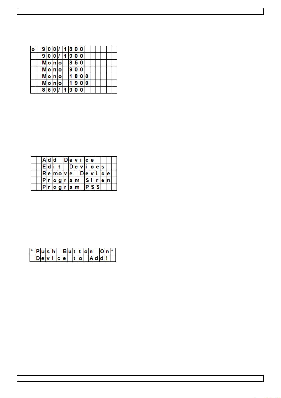
GSM band
Depending on service provider‟s network settings, you will need to adjust the GSM band setting accordingly.
Check with our local telecom service provider for the appropriate setting.
Stop
Select Stop and press OK key to save your settings and return to the previous menu.
9. Managing devices
The menu Devices+/- allows managing (add, configure, change, remove) devices like door contacts, PIR
sensors, sirens, etc. in up to 30 zones.
Order of installation
Indoor and outdoor sirens and universal receivers are considered auxiliary devices by the system. Before
adding one of these auxiliary devices, you need to add at least one other device first (a door contact, PIR
detector or remote control).
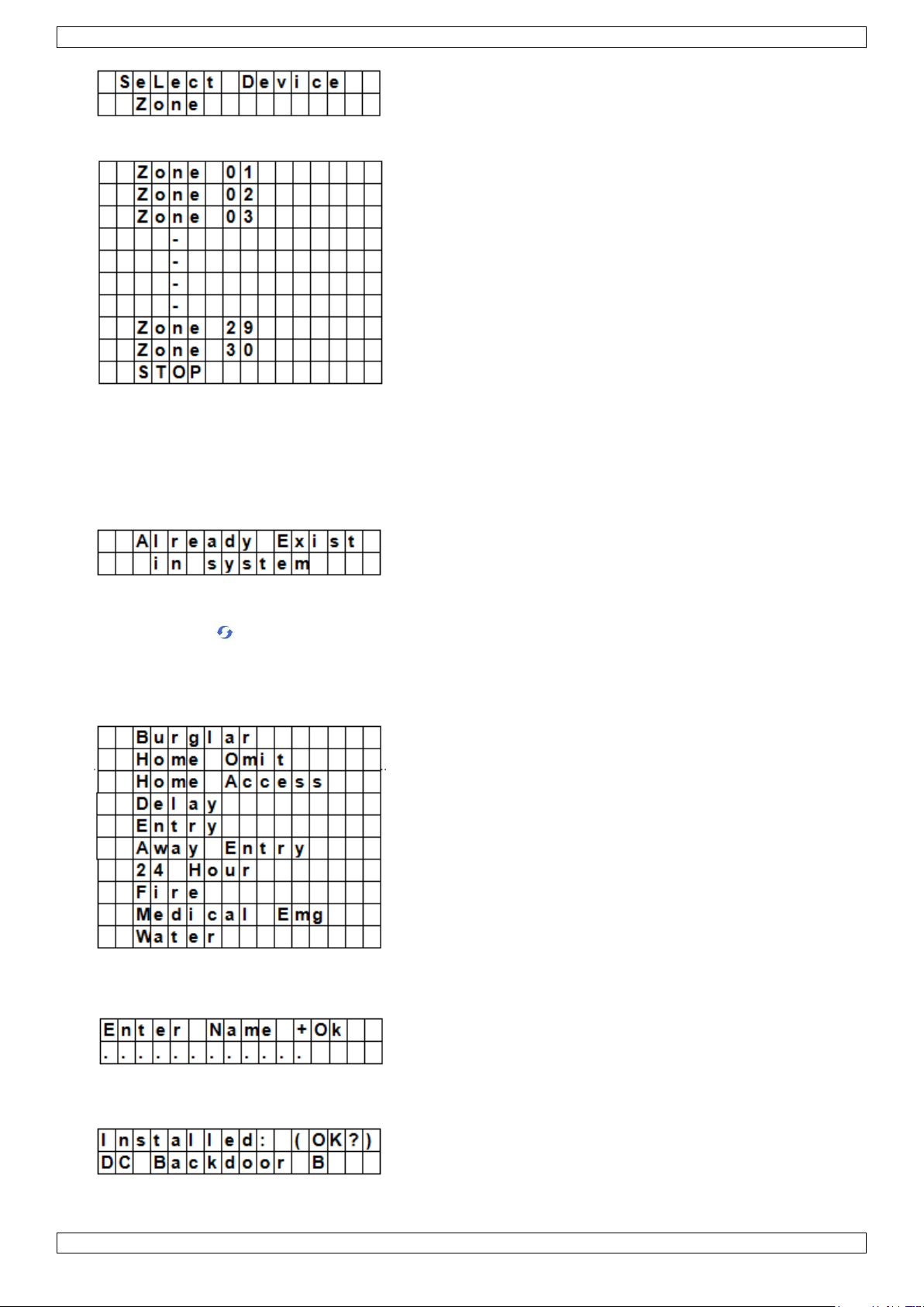
9.2 Add a device
To access the function:
1. Enter Program mode, go to Devices+/-, select Add device and press OK.
2. Press the test button on the device you want to add.
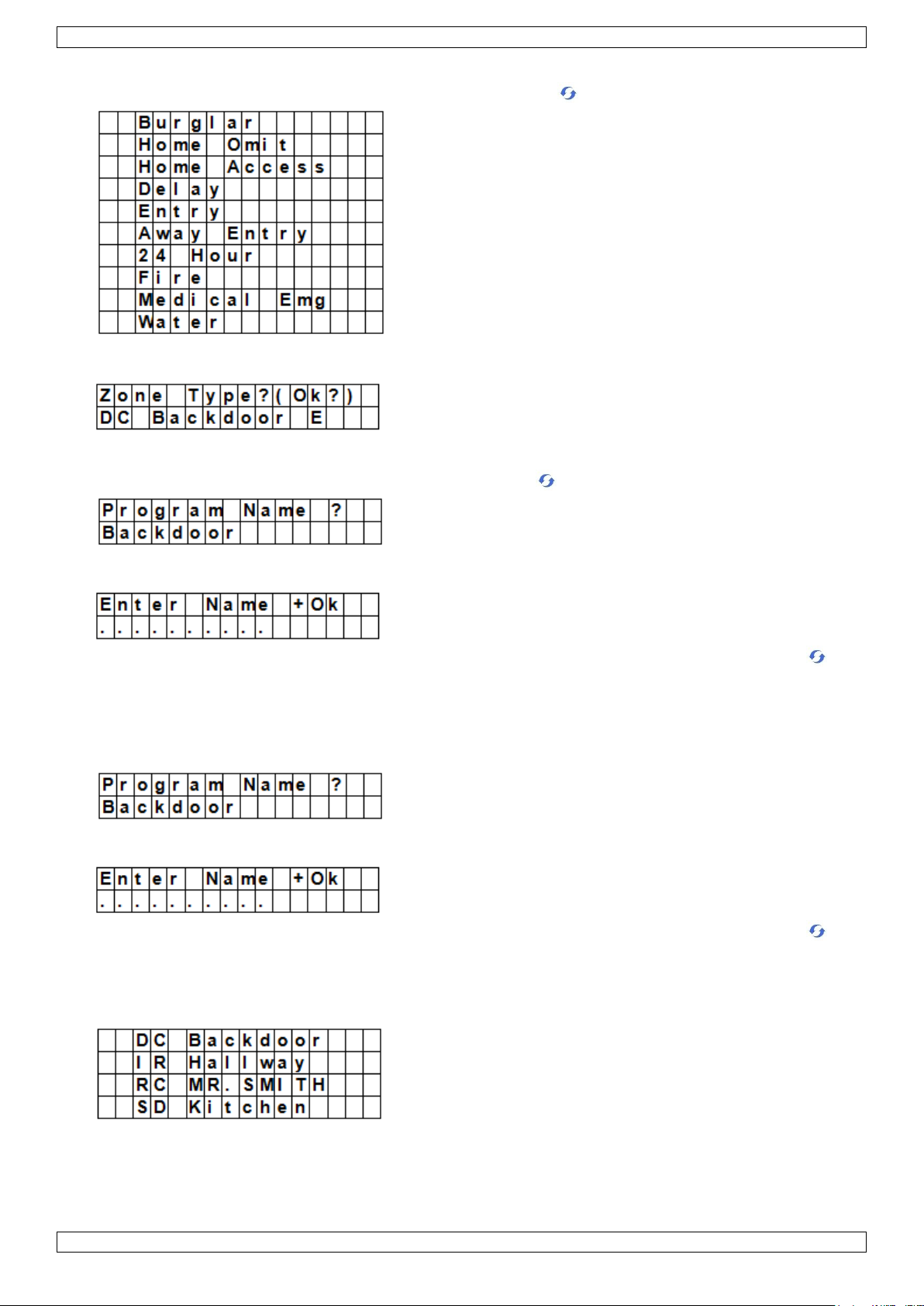
3. If the control panel detects the device, it will show the device type:
The possible devices are:
Door Contact
PIR Sensor
External PIR Sensor
Remote Controller
Remote Keypad
Water Sensor
Outdoor Siren
Universal Receiver
4. Press OK to confirm.
V. 01 – 12/06/2013 18 ©Velleman nv
Page 19
CTC1000
The control panel then displays the unused defense zones (up to 30).
5. Use the arrow keys to select the zone number to which you want to assign the device and press OK.
The procedure will now vary depending on the type of device you want to add.
6. Select Stop and press OK key to save your settings and return to the previous menu.
Notes
If you are trying to add a sensor that has already been added, an error message will appear.
To add this device anyway, you will need to remove it first (see section 9.5 Remove a device).
Pressing the key cancels the procedure.
Depending on the type of device you want to add, different screens will then be displayed accordingly for
further configuration purpose.
To add a door contact
1. Use the up and down arrows to select a working mode and press OK.
For details about the available working modes, see section 9.3.
2. Provide a zone name.
If you do not want to use a name, leave this field blank.
3. Press OK to confirm installation.
V. 01 – 12/06/2013 19 ©Velleman nv
Page 20
CTC1000
4. Press OK again to finish.
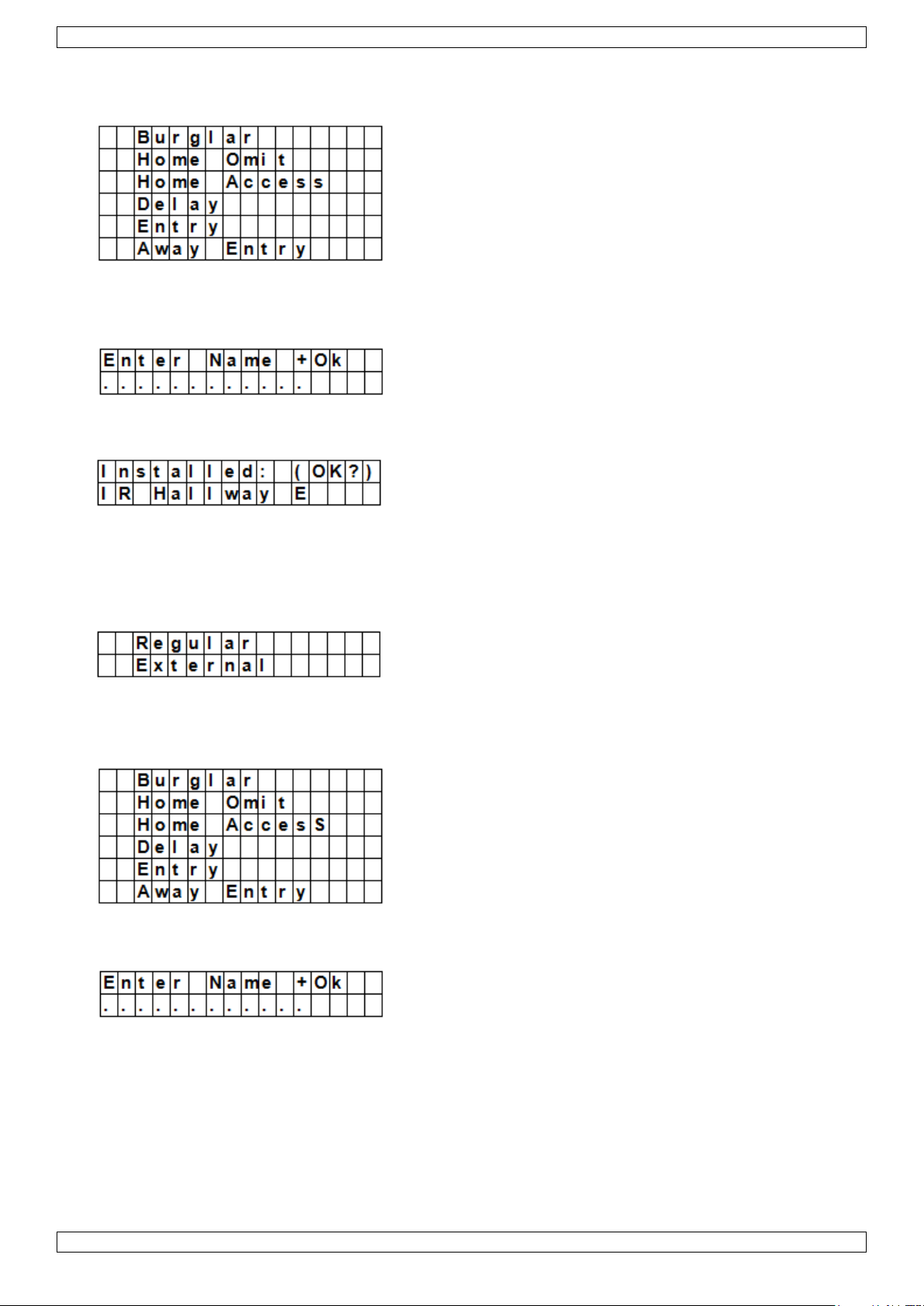
To add a PIR sensor
Assuming you have assigned a zone number (see section 9.2):
1. Use the up and down arrows to select a working mode and press OK.
For details about the available working modes, see section 9.3.
2. Provide a zone name.
If you do not want to use a name, leave this field blank.
3. Press OK to confirm installation.
4. Press OK again to finish.
To add an external PIR Sensor
Assuming you have assigned a zone number (see section 9.2):
1. Use the up and down arrows to select a PIR type and press OK.
o Regular: device will be added as an ordinary PIR
o External: device will be added as an external PIR.
2. Use the up and down arrows to select a working mode and press OK.
For details about the available working modes, see section 9.3.
3. Provide a zone name.
If you do not want to use a name, leave this field blank.
For information about entering text, see section 17.
4. Press OK to confirm installation.
5. Press OK again to finish.
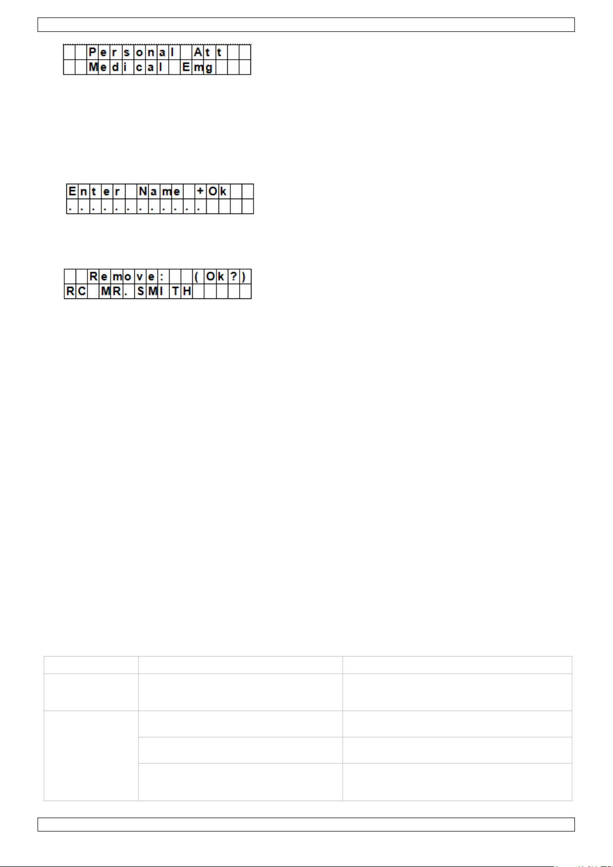
To add a remote control
Assuming you have assigned a zone number (see section 9.2):
V. 01 – 12/06/2013 20 ©Velleman nv
Page 21
CTC1000
Mode
System status
Device behaviour
Burglar
When the system is in Away Arm / Home
Arm, or during the Entry Delay or Exit
Delay period
if a burglar door contact is triggered, a burglar
alarm will be activated immediately
Home Omit
when the system is in away arm mode
(incl. away arm entry)
if a home omit door contact is triggered, a
burglar alarm will be activated immediately
when the system is in home arm mode, if
a home omit door contact is triggered
the control panel will not respond
during the entry delay or exit delay
period, if a home omit door contact is
triggered
the control panel will not respond
1. Use the up and down arrows to select the option you want for the remote control.
o Personal att: the control panel will give a personal attack alarm when the panic button is pressed for 3
seconds or twice within 3 seconds.
o Medical Emg: the control panel will give a medical emergency alarm when the panic button is pressed
for 3 seconds or twice within 3 seconds.
2. Use the up and down arrows to select a working mode and press OK.
For details about the available working modes, see section 9.3.
3. Provide a zone name.
If you do not want to use a name, leave this field blank.
For information about entering text, see section 17.
4. Press OK to confirm installation.
5. Press OK again to finish.
To add a remote keypad or water sensor
Installation is similar for all these device types.
Assuming you have assigned a zone number (see section 9.2):
1. Provide a zone name.
If you do not want to use a name, leave this field blank.
For information about entering text, see section 17.
2. Press OK.
3. Press OK again to finish.
To add an auxiliary device (Program Siren menu)
Indoor and outdoor sirens and universal receivers are considered auxiliary devices by the system. Before
adding one of these auxiliary devices, you need to add at least one other device first (detector or remote
keypad). The system displays an error message if this is not the case.
1. Enter Program mode, go to Devices+/-, select Program Siren, then Learn Siren and press OK.
2. Put the device you want to add into learning mode (see this device‟s user manual).
3. Press OK.
The control panel will sound a long beep and transmit learning code to all devices simultaneously. The
outdoor siren should respond by activating its siren and strobe light momentarily. The LED on the universal
receiver lights up for 3 seconds.
9.3 Add a device: overview of working modes
The overview below lists the possible modes for all devices taken together. The modes that are actually
available depend on the type of device you are adding.
V. 01 – 12/06/2013 21 ©Velleman nv
Page 22
CTC1000
Mode
System status
Device behaviour
Home Access
when the system is in away arm mode
if a home access door contact is triggered, a
burglar alarm will be activated immediately
when the system is in home arm mode
if a home access door contact is triggered, the
control panel will start an entry delay period to
give enough time to disarm the system
during the entry delay or exit delay
period
if a home access door contact is triggered, the
control panel will not respond
Delay
when the system is in away arm / home
arm mode
if a delay door contact is triggered, a burglar
alarm will be activated immediately
during the entry delay or exit delay
period
if a delay zone door contact is triggered, the
control panel will not respond
Entry
when the system is in away arm / home
arm mode
if an entry door contact is triggered, the
control panel will start an entry period to give
enough time to disarm the system
after the delay period is expired and no
correct pin code is entered to disarm the
system
the control panel will respond with a burglar
alarm after 30 seconds
when the system is in alarm off mode
if an entry door contact is triggered, the
control panel will sound a door chime (if
programmed).
Away Entry
when the system is in away arm mode
if an away entry door contact is triggered, the
control panel will start an entry period to give
enough time to disarm the system
after the delay period is expired and no
correct pin code is entered to disarm the
system
the control panel will respond with a burglar
alarm after 30 seconds
when the system is in alarm off mode
if an entry door contact is triggered, the
control panel will sound a door chime (if
programmed).
when the system is in home arm mode
if an away entry door contact is triggered, the
control panel will not respond
during the entry delay or exit delay
period
if an away entry door contact is triggered, the
control panel will not respond
24 Hour
Not applicable
the 24 hour door contact is active all the time
and does not have to be armed or disarmed
Fire
Not applicable
the fire door contact is active all the time and
does not have to be armed or disarmed
Medical Emg
Not applicable
a medical emg door contact is active all the
time and does not have to be armed or
disarmed
Water
Not applicable
the water door contact is active all the time
and does not have to be armed or disarmed
9.4 Edit a device
The function varies depending on the type of device you want to edit.
Edit a door contact – PIR sensor - remote control
Enter Program mode, go to Devices+/-, select Edit devices and press OK.
The display lists all the devices available.
V. 01 – 12/06/2013 22 ©Velleman nv
Page 23
CTC1000
1. Use the up and down arrows to select a device and press OK.
You can now change the device attribute. To skip this step, press .
2. Use the up and down arrows to select an attribute and press OK.
3. Press OK to confirm.
You can now change the device name. To skip this step, press . To continue, press OK.
4. Enter a zone name and press OK.
The display returns to the device list. Use the up and down arrows to select another device or press .
Edit a remote keypad – water sensor
1. Enter Program mode, go to Devices+/-, select Edit devices and press OK.
The display lists all the devices available.
2. You can now change the device name.
3. Enter a zone name and press OK.
The display returns to the device list. Use the up and down arrows to select another device or press .
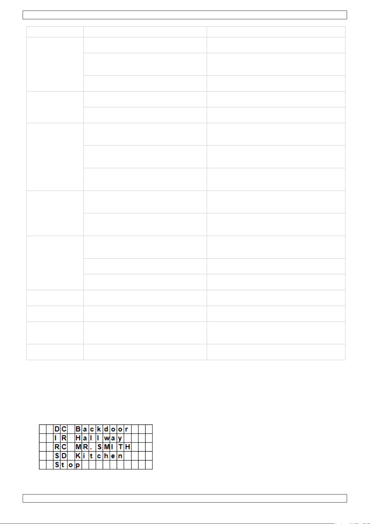
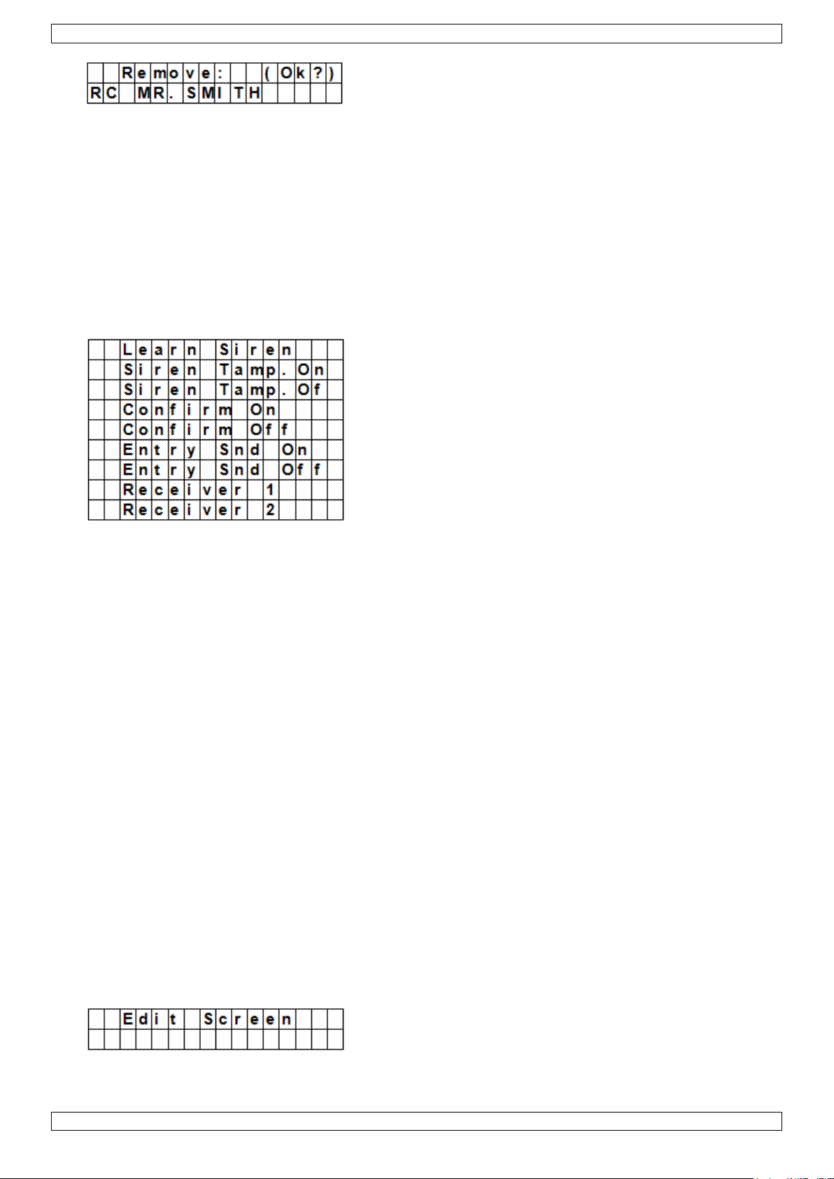
9.5 Remove a device
1. Enter Program mode, go to Devices+/-, select Remove device and press OK.
The system lists all available devices.
2. Use the up and down arrows to select a device and press OK.
For details about the available working modes, see section 9.3.
V. 01 – 12/06/2013 23 ©Velleman nv
Page 24
CTC1000
3. Press OK again to confirm.
9.6 Program Siren menu – other options
Learn Siren
To add an outdoor bell box, indoor bell box or universal receiver… it should be programmed first by the control
panel, so that the control panel can communicate with these auxiliary devices.
Before adding one of these auxiliary devices, you need to add at least one other device first (a door contact,
PIR detector or remote control).
To add an outdoor or indoor siren:
1. Put the device or devices you want to add in learn mode.
2. Enter Program mode, go to Devices+/-, select Program Siren and press OK.
3. Use the up and down arrows to select Learn Siren and press OK.
o The control panel will then sound a long beep and transmit learning code to all devices simultaneously.
o The outdoor siren will respond by activating its siren and strobe light momentarily.
4. Place these auxiliary devices out of Learn mode. Adding them into the system is completed.
Siren Tamp. On - Siren Tamp. Off
The outdoor siren tamper switch can be enabled and disabled remotely.
This is used especially when replacing siren battery.
To disable the siren tamper: select Siren Tamp.Off and press OK.
All added sirens will temporarity lose their tamper protection simultanously.
To enable the siren tamper: select Siren Tamp.Off and press OK.
The tamper protection will be set simultaneously for all sirens.
Confirm On - Confirm Off
When set to on, the outdoor siren will sound a confirmation beep when arming or disarming the system.
When set to off, the outdoor siren will not sound a confirmation beep when arming or disarming the
system.
Select Confirm On or Confirm Off and press OK.
Entry Snd On - Entry Snd Off
Enables or disables entry delay warning beeps on the siren when you enter the house.
Select Entry Snd On or Entry Snd Off and press OK.
10. Other configuration functions
SMS Editor
The control panel editing the SMS message that will be sent to your mobile phone when an alarm occurs.
V. 01 – 12/06/2013 24 ©Velleman nv
Page 25
CTC1000
1. Enter Program mode and select SMS Editor from the menu.
The Edit Screen appears.
2. Enter an sms message (up to 16x4 characters).
For information about entering text, see section 17.
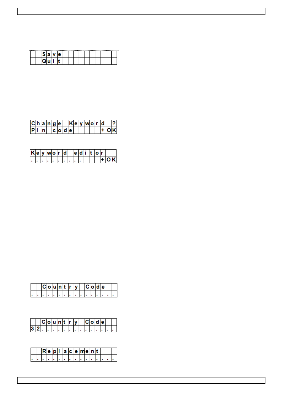
3. Press OK.
4. Select Save and press OK to confirm.
SMS Keyword
The control panel supports remote commands sent from a mobile phone to the system. Before sending remote
commands, you will first need to enter a password called SMS keyword. The default keyword is the same as the
default pin code (see section 7.4 Pin code).
To change the pin code for remote commands:
1. Enter Program mode, select SMS Keyword from the menu and press OK.
2. Key in a 4 digit code and press OK.
3. Repeat the code and press OK.
Country Code
The display format of the telephone number (with or without country code) may vary depending on the mobile
phone provider.
If your mobile phone displays numbers without the country code, you can ignore this section.
If your mobile phone displays numbers with the country code, you need to change a setting in the control
panel.
You can ask this to your provider or test it yourself as follows:
1. Insert the SIM card you will use for the control panel in a mobile phone.
2. Turn on the phone.
3. Make sure the number is not assigned to any contact on your phone.
4. Send an sms message to the same number.
o If your mobile phone displays numbers without the country code (for example 01234567890), you can
ignore this section.
o If your mobile phone displays numbers with the country code (for example +321234567890), proceed
as follows.
5. On the control panel, enter Program mode, go to Country Code and press OK.
6. Enter the country code of your country.
Example: if the number displayed on your phone was +321234567890, type 32 (without the „+‟).
7. Press OK.
8. In the Replacement screen, key in 0.
V. 01 – 12/06/2013 25 ©Velleman nv
Page 26
CTC1000
9. Press OK to finish.
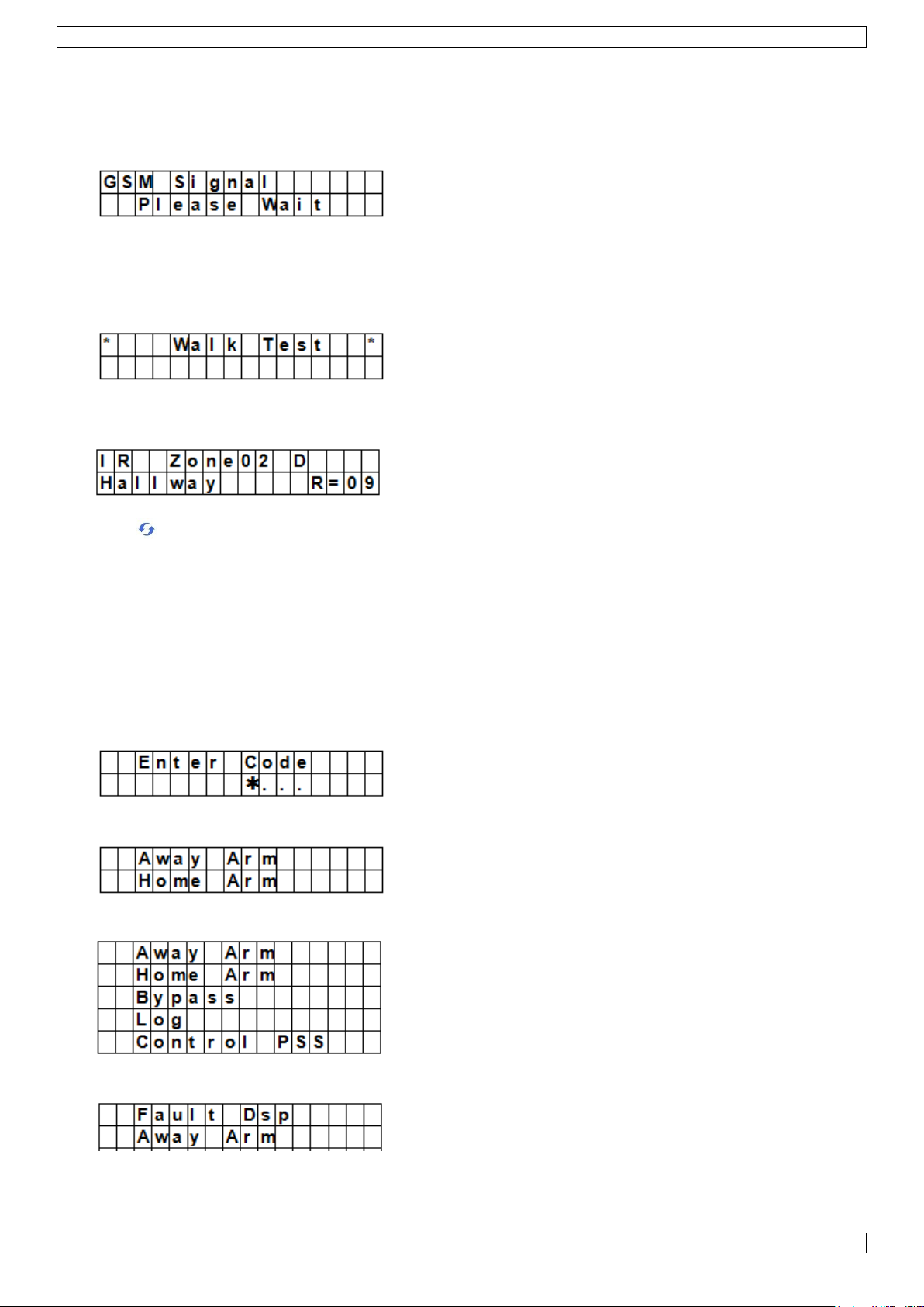
GSM Signal
The option GSM signal allows monitoring the signal strength.
1. On the control panel, enter Program mode, go to GSM signal and press OK.
The system will display the signal strength (from 0 to 9, 9 being the strongest signal).
Walk Test
The option Walk Test checks the communication between the control panel and any device.
1. On the control panel, enter Program mode, go to Walk Test and press OK.
2. Press the Test button on the device you want to test.
If the control panel receives a signal, it will display the device‟s name, zone and signal strength.
3. Press to exit.
Reset GSM
The option Reset GSM resets the mobile phone signal.
1. On the control panel, enter Program mode, go to Reset GSM and press OK.
The signal takes about 1 minute to reset.
11. Using the alarm
When the alarm is disarmed (off), enter a pin code to access the user menu. From this menu, you can set the
alarm on or off.
Enter the first digit of your pin code.
1. Within 10 seconds, enter the other digits of the pin code. The display shows:
2. The cursor blinks next to Away Arm. The full menu contains the following items:
If the system has detected an error, the first line of the display will show:
11.2 Arming the system
If the system is disarmed, you can arm it as follows:
V. 01 – 12/06/2013 26 ©Velleman nv
Page 27
CTC1000
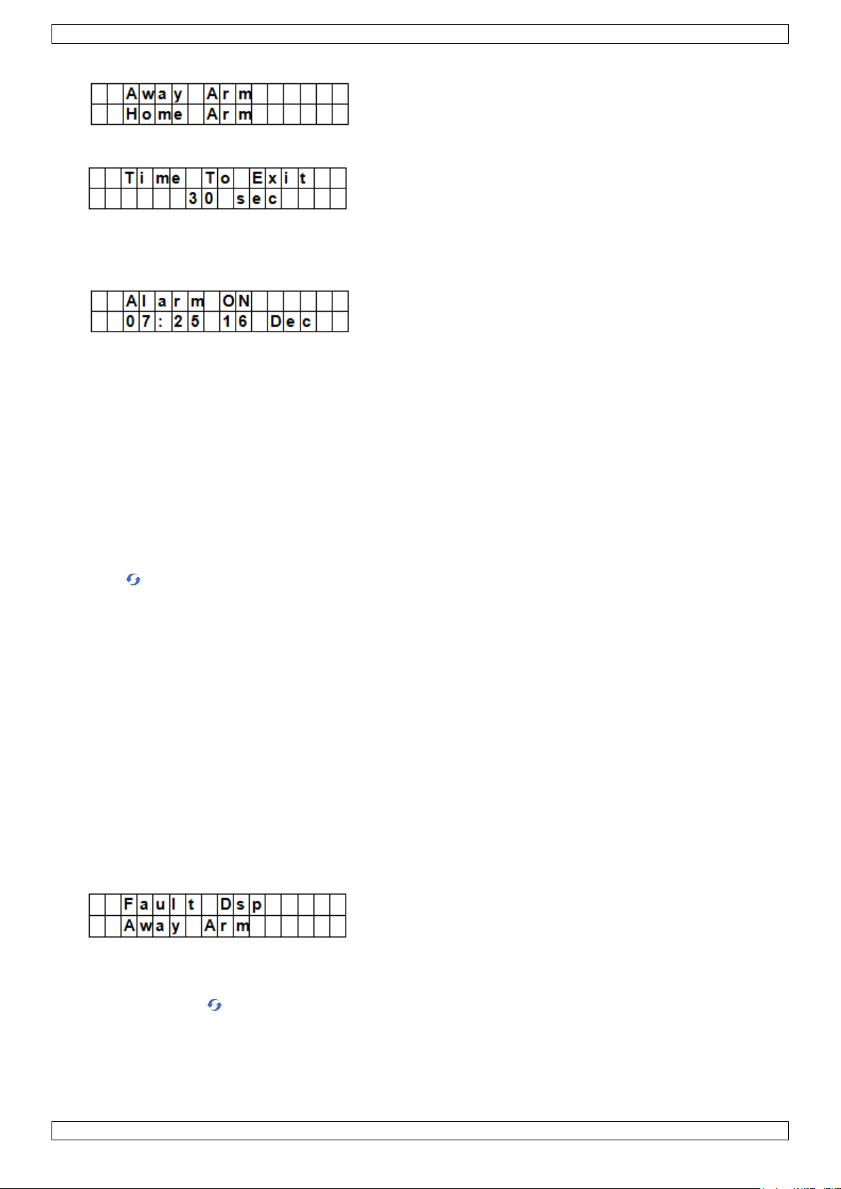
1. Enter your pin code and press OK. The display shows:
2. The cursor blinks next to Away Arm. Press OK. The display shows:
o The control panel starts the countdown and plays a sound.
(The sound and actual exit time depend on your settings, see 7.9.)
o When the countdown time is up, the system will play a long sound and the system will be armed.
Notes
The control panel has a screen saver function. The Alarm ON message will be displayed for 180 seconds.
After that, the display shows only current date and time.
If the Final Door Set Option is set to ON, the control panel will enter Alarm On mode as soon as the door
has been closed.
If a door contact or PIR sensor has been triggered (for example a door is still open), you cannot arm the
system. To arm the system anyway, see section Force arming the system below.
The system can also be armed with the (optional) remote control.
Stopping the exit delay
When you have armed the system and the countdown timer is still running, the exit delay can be stopped by
disarming the system.
1. Press key.
The screen will ask you to enter the pin code.
The counting down delay is displayed on the control panel.
2. Enter your pin code and press OK.
Alarm Off will be displayed on the screen and the system returns to Disarmed mode.
o The exit delay can also be stopped by pressing the Disarm button on the (optional) remote control.
o If the exit delay period times out before the code can be entered, the system will be armed.
Extending the exit delay (remote control only)
During the exit delay period, the delay time can be extended by pressing the Arm button on the (optional)
remote control.
Press and hold the Arm button for 1 second and you will hear a long beep to confirm the extension of exit
time.
Every time you press the Arm button on the remote, the delay time starts counting from the beginning.
11.3 Force arming the system
If you are entering your pin code while the system has detected an error, the control panel displays an error
message.
If you then select Away Arm and press OK, the control panel will play a warning sound indicating arming is
prohibited. The display will then alternatively display the actual errors and the message Fault Dsp.
You will need to press key to return back to Alarm Off Screen.
If an error occurs, you can
solve the problems and clear the error display (see section 14) and arm the system (recommended).
ignore the errors and arm the system despite the errors, as follows:
In the Fault Dsp screen:
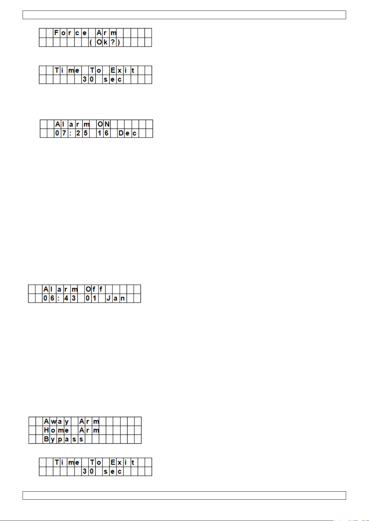
1. Enter your pin code and press OK. The display shows:
V. 01 – 12/06/2013 27 ©Velleman nv
Page 28
CTC1000
2. Press OK to confirm.
o The control panel starts the countdown and plays a sound.
(The sound and actual exit time depend on your settings, see 7.9.)
o When the countdown time is up, the system will play a long sound and the system will be armed.
Arming with door opened
While you arm the system, if any door was detected to be open, the control panel will also sound a warning
to indicate arming is prohibited. The message Fault DSP is displayed in the middle of the top display row
and alternates at 2-second intervals with the sensor name that is being triggered.
At this moment, you can close the opened door, after which the error display will be cleared automatically
and the screen returns to Alarm off. You can the arm the system.
If you want to put the system into Arm mode with the door opened, you can use Forced Arming.
Notes
The Fault DSP screen has a time-out for 5 minutes. It will automatically exit and return to Alarm Off screen
after 5 minutes.
If a sensor is by-passed (see section Partial Arm mode), the condition of that sensor will not be checked.
If a sensor tampered or out-of-order occurs, you can temporarily by-pass it or permanently remove it.
11.4 Disarming the system
You can disarm the system if it is either in Away Arm mode or Home Arm mode (Alarm ON):
1. Enter your pin code and press OK. The control panel will sound 2 short beeps and return to disarmed mode.
Remote control
When the system is in Home mode (see below), pressing the Disarm button on the remote control will
disarm the system.
When the system is in Away Arm mode, pressing the Disarm button on the remote control can disarm the
system when either an Entry device has been triggered, or when the Remote Controller Entry Enable has
been set to ON (see section RC Ent E (= remote controller entry enabled) in chapter 8).
11.5 Home Arm mode
The Home mode allows the home to be armed so that no one can get inside without first disarming the system,
yet the person already inside the house can move freely without triggering the alarm.
You can only enter the Home Arm mode when the system is disarmed.
To activate Home mode:
1. Enter your pin code and press OK.
2. Press key to move the cursor down to select Home Arm and press OK.
V. 01 – 12/06/2013 28 ©Velleman nv
Page 29
CTC1000
o The control panel starts the countdown and plays a sound.
(The sound and actual exit time depend on your settings, see 7.9.)
o When the countdown time is up, the system will play a long sound and the system will be armed.
Notes
The system can also be armed with the (optional) remote control
To stop the exit delay, see section Stopping the exit delay in chapter 11.2.
To extend the exit delay, see Extending the exit delay (remote control only) in chapter 11.2.
If the system has detected an error and you want to arm the system anyway, see section 11.3 Force
arming the system.
11.6 Partial arm mode (by-pass mode)
The Partial Arm mode allows the user to de-activate (by-pass) any sensors at their discretion. This feature
allows your home to be armed; yet the person inside the house can move freely in the area where the sensor is
by-passed.
To activate Partial arm mode:
1. Enter your pin code and press OK.
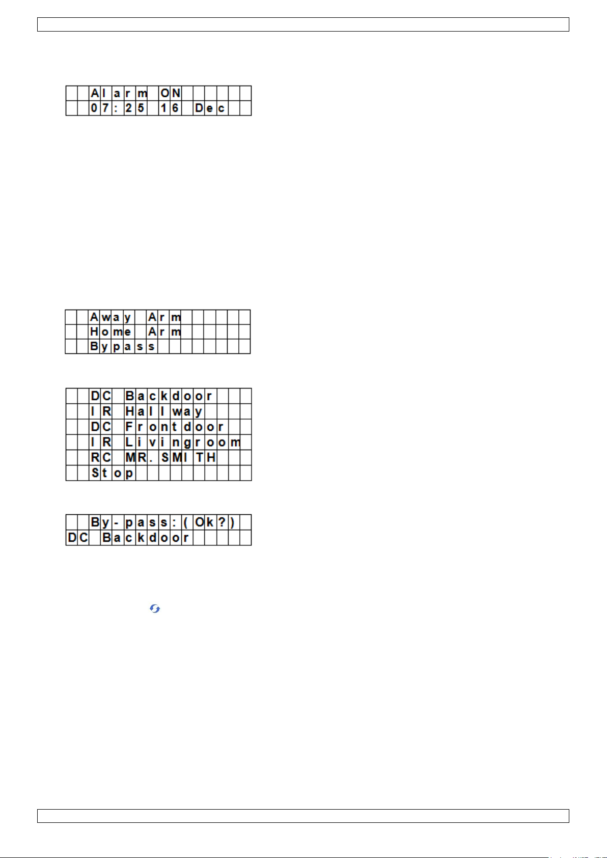
2. Press key to move the cursor down to select Bypass and press OK.
3. Press & keys to select the zone to be by-passed and press OK (for example: DC backdoor).
4. Press OK to confirm.
The bypassed zone will be marked with a *.
5. Repeat steps 2-4 to by-pass another device.
6. When done, press key to return to user menu and the cursor stays at Arm.
7. Press OK.
Notes
If a sensor is by-passed, the control panel will not respond to its triggering in Arm mode.
The by-pass setting is effective for only one time, once the system is disarmed, the by-pass setting is
cleared automatically.
When a sensor is by-passed, the system can be armed directly regardless of its error situation (if any).
However, its situation is still being monitored and will be logged and displayed when you access the Log
submenu.
11.7 Stopping an alarm
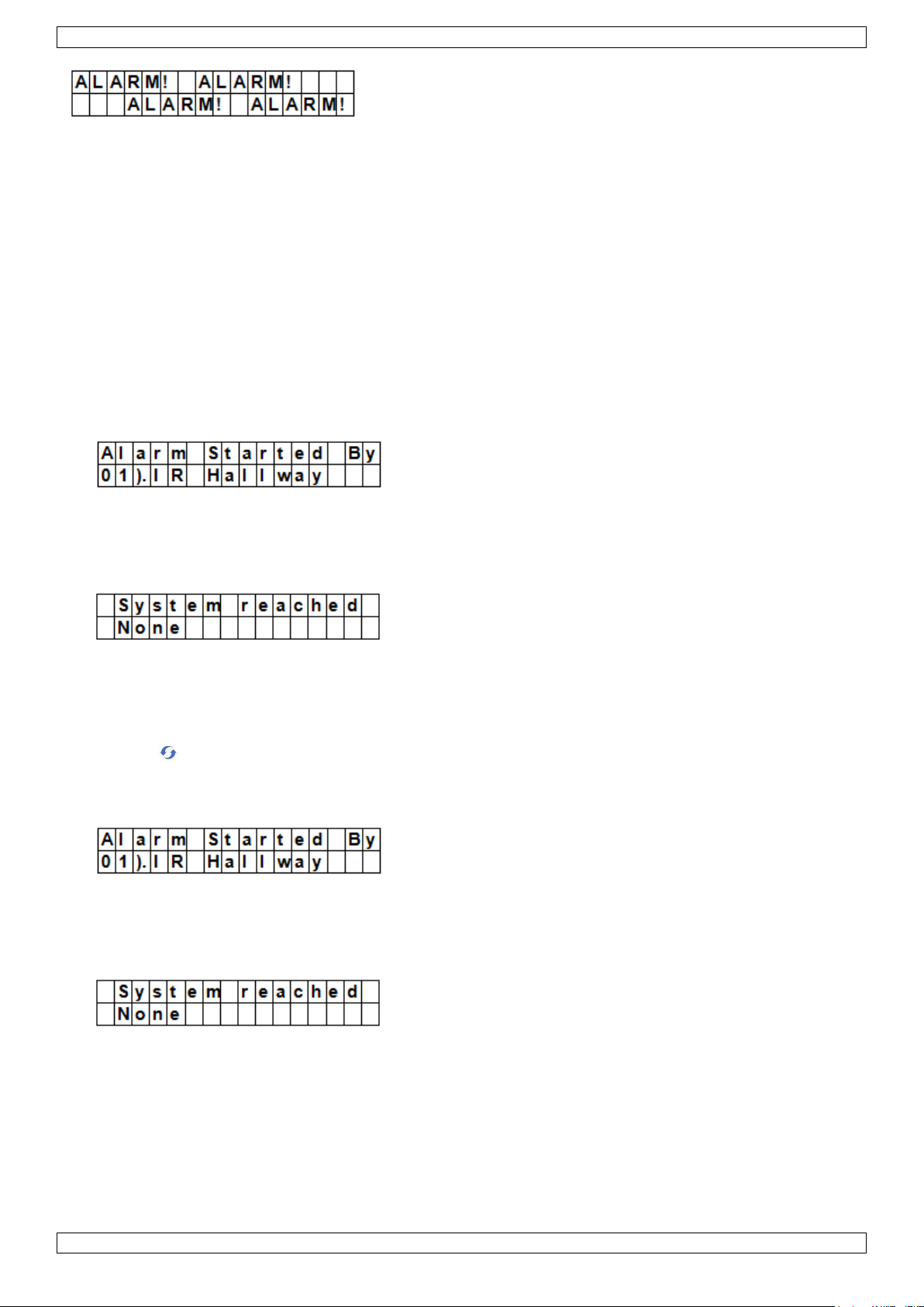
During any alarm, the control panel will sound its siren and report to the programmed mobile phone number.
The display shows:
V. 01 – 12/06/2013 29 ©Velleman nv
Page 30
CTC1000
During an alarm, to stop the siren and clear the display:
Key in your pin code and press OK.
If the pin code is correct, the alarm sounding will be stopped.
If you press any key other than the first digit of your pin code, the screen will prompt you to enter your pin
code.
Reporting
The reporting behaviour varies depending on when you stop the alarm
Before reporting has started
While reporting is on-going
After reporting was finished
Alarm stopped before reporting has started
The system will not send any alarm reports.
1. The display will show the device that triggered the alarm with its zone number.
2. Press OK.
If multiple alarms have been raised, the control panel continues displaying the 2nd alarm event with 02). at
the beginning of the 2nd line.
3. Repeat pressing OK until the display shows:
[meaning: system did not reach any phone numbers]
4. Press OK.
The display returns to Alarm off.
Or press to review all events.
Alarm stopped while reporting is on-going
1. The display will show the device that triggered the alarm with its zone number.
2. Press OK.
If multiple alarms have been raised, the control panel continues displaying the 2nd alarm event with 02). at
the beginning of the 2nd line.
3. Repeat pressing OK until the display shows:
[meaning: system did not reach any phone numbers]
4. Press OK.
The display returns to Alarm off.
Alarm stopped after reporting was finished
1. The display will show the device that triggered the alarm with its zone number.
V. 01 – 12/06/2013 30 ©Velleman nv
Page 31

CTC1000
Type of
Alarm
Disarmed
Away Arm
Home Arm
Exit Timer
Away Arm Entry
Timer
Home Arm Entry
Timer
Burglar
No response
Instant Burglar
Alarm
Instant Burglar
Alarm
Instant Burglar
Alarm
Instant Burglar
Alarm
Instant Burglar
Alarm
Home Omit
No response
Instant Burglar
Alarm
No response
No response
Instant Burglar
Alarm
No response
Home
Access
No response
Instant Burglar
Alarm
Start Entry Timer
No response
No response
No response
Delay
No response
Instant Burglar
Alarm
Instant Burglar
Alarm
No response
No response
No response
Entry
Door Chime
Start Entry Timer
Start Entry Timer
No response
No response
No response
Away
Entry
Door Chime
Start Entry Timer
No response
No response
No response
No response
24 HR.
Burglar Alarm
Burglar Alarm
Burglar Alarm
Burglar Alarm
Burglar Alarm
Burglar Alarm
2. Press OK.
If multiple alarms have been raised, the control panel continues displaying the 2nd alarm event with 02). at
the beginning of the 2nd line.
3. Repeat pressing OK until the display shows:
[showing the number reached by the control panel]
4. Press OK.
The display returns to Alarm off.
Or press to review all events.
Remote control
When an alarm (other than Panic alarm) is raised, pressing the Disarm button on the (optional) remote
control will also stop the alarm.
A Panic Alarm cannot be silenced from the remote control but needs to be silenced on the control panel.
This is to prevent the remote control from being snatched from the user and silence the alarm using the
Disarm button on the remote.
Alarm memory
If an alarm was raised without being silenced during your absence and the alarm reporting has been carried
out, the screen will stay on the Alarm warning display.
You cannot reset the display using the remote control.
To clear the display, follow the same steps as described in chapter 11.7.
11.8 Alarm events and responses
The following table lists the alarm events and how the control panel will respond to them.
V. 01 – 12/06/2013 31 ©Velleman nv
Page 32

CTC1000
Fire
Fire Alarm
Fire Alarm
Fire Alarm
Fire Alarm
Fire Alarm
Fire Alarm
Medical
Emergency
Alarm
Emergency Alarm
Emergency Alarm
Emergency Alarm
Emergency Alarm
Emergency Alarm
Water
Water Alarm
Water Alarm
Water Alarm
Water Alarm
Water Alarm
Water Alarm
External PIR
No response
Instant Burglar
Alarm
(but no reporting)
Warning Beep
No response
No response
No response
12. Event log
The alarm log memorises the last 20 system events including
all alarm events with device ID
all error warning events
all arming and disarming events
The logged events are displayed in reversed chorological order (most recent event first).
The log is marked with a Start label before the most recent entry and End after the oldest entry.
To view the event log:
While in alarm off mode:
1. Key in the user code and press OK to access User‟s Menu.
2. Press the key repeatedly to select Log and then press OK.
The start of the log will be displayed.
3. Use & to scroll through all logged events.
13. False Alarm Management
The device features the following false alarm management functions:
Twofold entry warning
When the system is armed and a device set to “entry” attribute is triggered, the system will begin an entry
countdown timer according to your entry time setting in General Setting. The purpose of the countdown timer is
to warn that alarm reports to the programmed telephone number are about to be made.
During the entry countdown timer, if another device not set to “entry” attribute is triggered, or a valid user pin
code is not entered before the timer expires, an alarm will be activated.
After the alarm is activated, the system will wait another 30 seconds before sending reports to programmed
telephone numbers.
If a valid user pin code is entered within 30 seconds, the alarm will be aborted and the system returns to
normal status.
If no valid user pin code is entered, the system will report burglar alarm to programmed telephone numbers.
Reporting of arming and disarming actions
If the Latch option is set to ON (factory default), all arming and disarming actions with user pin codes or
remote controllers will be reported.
Sequential verification reporting
If Verification is set to ON (factory default is OFF) and a burglar alarm is activated, if another different device
set to burglar attribute is triggered within 30 minutes, the system will send an alarm confirm report to the
programmed telephone numbers. Refer to section Verification on page 16 for details.
The sequential verification report will be sent in addition to the alarm report.
If the second device is triggered within the countdown delay, the sequential verification report will not be sent.
V. 01 – 12/06/2013 32 ©Velleman nv
Page 33

CTC1000
Control panel
A tamper switch prevents the device from any removal attempts away
from its cross mounting bracket
Power supply
A tamper switch protects the power supply lid from being opened or
removed.
PIR Sensor
A tamper switch protects the enclosure from being opened.
A back-tamper protects the unit from being removed from its mounting
location.
Door contact
A tamper switch protects the enclosure from either being opened or being
removed from the mounting surface.
Sensor Low battery
The device detects low battery for the PIR sensor, door contact, remote
keypad, water sensor, remote controller.
Sensor out-of-order
The PIR sensor, door contact, water sensor will send signals to the panel
at intervals between 30~50 min. The system will send an out-of order
report if a device no longer sends a supervision signal.
If the control panel does not receive the supervision signal from the device
(see section Supervision in Chapter 8 Special Settings), the control panel
will sound an alarm and yellow LED will light while an error message can
be viewed on the LCD (in the Fault Display menu).
Interference
The device can detect interference on 868 MHz frequency band.
After a continuous interference signal is present for more than 30 seconds,
an interference event can be logged, displayed on the LCD (in the Fault
Display menu).
SIM Card missing
If the SIM card is missing, a warning message will be shown.
GSM out of signal
If out of signal, change the position of the control panel to get a better
signal.
14. Errors
The control panel can detect the following errors:
control panel Low Battery
AC Power Fail
Sensor Out-of-order
Sensor Low Battery
Device and control panel Tamper
Interference Detection
SIM card missing
GSM out of signal
If the control panel detects an error, it will display an error.
Possible errors
Fault message display
When any error persists, the control panel will respond as below when it is disarmed:
The yellow LED will light to indicate the error
The LCD will display the type of error and the source of the error in the Fault Display section of the user
menu.
A warning beep will sound every 30 seconds.
If an error is detected while the system is in full arm mode, the error will not be shown until the system is
disarmed.
Clearing error message display
The yellow LED will turn off automatically once all errors are restored, or any devices in error are removed. It
cannot be cleared manually.
The error message display remains even if the errors have been restored.
The error message can only be cleared manually after the error has been corrected.
Viewing/clearing the error message
To check the error, when the system is disarmed.
1. Enter your pin code and press OK.
V. 01 – 12/06/2013 33 ©Velleman nv
Page 34

CTC1000
AC Power fail
The yellow LED will light and the error message will be
displayed.
The panel will report the error by SMS to the first telephone
number in all modes within 15-30 minutes.
Once AC Power is restored, the panel also will report the restore
event by SMS to the first telephone number within 15-30
minutes.
control panel low battery
Any time the system detects battery Low on the panel, yellow
LED will light while this error message can be viewed on LCD
under Fault Display.
When control panel is powered by an AC adapter, the control
panel is incapable of detecting low battery condition.
sensor low battery
If the low battery is detected on any sensor, yellow LED will light
up at any time. The error message can be viewed on LCD under
Fault Display in the user menu.
panel sabotaged
If the Tamper switch on the control panel is triggered, yellow
LED will light. The error message can be viewed on LCD under
Fault Display in the user menu.
In addition, the panel will report the error by SMS to the first
telephone number in all modes.
sensor sabotaged
If the tamper switch on the PIR sensor, door contact, remote
keypad, or outdoor siren is triggered, the yellow LED will light.
The error message can be viewed on LCD under Fault Display in
the user menu.
In addition, the panel will report the error by SMS to the first
telephone number in all modes.
The siren will sound alarm for tamper-trigger according to the
Tamper Alarm setting (see section Tamper Alarm in chapter 8).
sensor out-of-order
When the control panel has not received the supervisory signal
from each individual PIR sensor or door contact, etc. for a period
(according to the setting of the Supervision), the yellow LED on
2. The screen will display
Fault Dsp
Arm
with the cursor next to Fault Dsp.
3. Press OK key to select Fault Dsp.
All the errors are listed.
4. Use the & keys to move the cursor up or down.
5. After viewing all the errors, press key, a prompt message is displayed.
Clear Fault
Dsp (OK?)
6. If the error has been corrected, press OK.
The error will be cleared and the screen returns to Alarm off.
Notes
If the error has not been corrected, the display will not be cleared. It will appear again while you try to arm
the system and the error prevents the system from being armed. The error display can be cleared only
after the error has been corrected.
Even when the error message is cleared, the error will still be retained in the log.
14.2 Error Response
When an error is detected, in addition to the error display, the control panel will also respond depending on
the nature of the event.
Except for sabotage alarms, the control panel and external sirens will not sound audible siren for error.
In all modes, when Panel AC power failure or tamper trigger happens, the control panel will send error
reports by SMS. For all other errors, the control panel will NOT send error report by SMS.
V. 01 – 12/06/2013 34 ©Velleman nv
Page 35
CTC1000
the panel will light while this error message can be viewed on
LCD under Fault Display. No alarm event will be reported.
interference
When the system is programmed with Interference detection ON
and when there is an interference detected for 30 seconds, the
yellow LED will light up. The error message can be viewed on
LCD under Fault Display in the user menu.
Message displayed
Meaning
AC failure
AC Power Fail
GSM Signal
GSM out of signal
Interference
interference detected
Panel L.B.
low battery on the control panel
Panel Tamper
sabotage on the control panel
(Sensor w/ Zone Name) + L.B.
low battery on the sensor
(Sensor w/ Zone Name) + out
sensor out-of-order
(Sensor w/ Zone Name) + Tamper
sabotage on a sensor
Sim Card?
SIM card missing
Message displayed
Meaning
(DC w/ Zone Name) + open
Door Contact triggered
(IR w/ Zone Name) + Active
PIR triggered
Control Command
Action
00
On Hook
01
Listen-in
10
Disarm
11
Arm
20
UR#1 deactivate
21
UR#1 activate
30
UR#2 deactivate
14.3 Error messages
The error message is displayed in short form as below:
Example: the message DC Z 01 L.B. means Zone 1 Door Contact is low battery.
Note
While you arm the system, if any of door contact or PIR is triggered, arming is also prohibited and the sensor
triggered will be displayed as error message.
15. Remote Commanding
The unit can be controlled by remote control commands sent via sms messages.
15.1 Remote commanding from a regular phone line
1. Dial the GSM phone number of your control panel and hang up on the first ring.
2. Dial the control panel again after 8 to 20seconds.
You will hear 2 beeps from the control panel via phone set.
3. Enter the user pin code (user 1 ~ user 4).
The first digit of pin code should be entered within 3 seconds.
A valid pin code should be entered with 20 sec. otherwise the Panel will hang up automatically.
4. If the pin code is correct, you will hear 2 beeps from the control panel via phone set.
5. Enter the 2-digit DTMF Control Command.
If the command is correct, you will hear 2 beeps; if not, you will hear 1 beep.
DTMF Remote Control Command Table
V. 01 – 12/06/2013 35 ©Velleman nv
Page 36

CTC1000
31
UR#2 activate
Control Command
Action
00
hang up with Confirmation
10
disarm
11
arm
20
UR#1 deactivated
21
UR#1 activated
30
UR#2 deactivated
31
UR#2 activated
M I C H A E L * 1 2 3 4 1 1 0 0
The
programmed
SMS keyword
User pin
Code
Remote
Control
Command
M I C H A E L * 1 2 3 4 1 1
The programmed
SMS keyword
User
pin
Code
Remote
Control
Command
Example: if the Listen-in communication is activated by DTMF01, no DTMF command can be set for further
operation.
15.2 Remote commanding via SMS message
Remember to change the Language setting of your mobile phone to English before proceeding.
SMS Remote Control Command Table
For 2-digit Remote Control Command
Send the SMS message to command the Unit to enter Arm Mode and send a confirmation SMS back to your
mobile phone. The format is:
A confirmation SMS message will read on your mobile phone as: Confirmation, MICHAEL* 1234 11 00
Send the SMS message to command the Unit to enter Arm Mode without a confirmation SMS back to your
mobile phone. The format is
The system will automatically filter through all incoming SMS messages for SMS Keyword and automatically
ignores and deletes SMS which does not contain the SMS keyword. For all authorized remote command that
comes with proper keyword and pin code, the system will immediately carry out the contained command(s) and
delete the SMS message afterward.
16. System reset
When resetting the control panel, all programmed parameters (including pin codes) are reset to factory defaults
and all devices are removed. You have to do the programming and add the devices one by one again.
The control panel can clear all programmed parameters by the following sequence:
1. Remove the power supply and remove the backup battery.
2. Apply power while holding down the key.
3. Release the key when you hear a tone.
The control panel will display Enter Code.
4. Enter the following key sequence: , OK key
5. Press OK.
If you enter an incorrect key, the unit will revert to normal Alarm On mode.
V. 01 – 12/06/2013 36 ©Velleman nv
Page 37

CTC1000
power supply
100-240 Vac/50-60 Hz - 12 Vdc 500 mA (adapter incl.)
back-up battery
7.2 V 600 mAh Ni-Mh rechargeable battery (incl.)
battery back-up time
± 8 hours
sound level
± 104 dB @ 1m
frequency
868.6375 MHz
operating temperature
-10 to +45 °C
humidity
up to 90 % non-condensing
dimensions
185 x 120 x 26 mm
weight
420 g
17. Entering text
The keypad can be used to enter text for user names, zone names, SMS texts…
Locate the numeric key displaying the letter or symbol you want to enter and press it repeatedly until the
letter or symbol appears.
Release the key and the flashing cursor automatically jumps to the next position for you to continue with
the next letter by the same method.
18. Technical Specifications
Use this device with original accessories only. Velleman nv cannot be held responsible in the event
of damage or injury resulting from (incorrect) use of this device.
For more info concerning this product and the latest version of this manual, please visit our website
www.velleman.eu.
The information in this manual is subject to change without prior notice.
© COPYRIGHT NOTICE
The copyright to this manual is owned by Velleman nv. All worldwide rights reserved. No part of this
manual may be copied, reproduced, translated or reduced to any electronic medium or otherwise without the
prior written consent of the copyright holder.
V. 01 – 12/06/2013 37 ©Velleman nv
Page 38

CTC1000
Houd dit toestel uit de buurt van kinderen en onbevoegden.
Gebruik het toestel enkel binnenshuis.
Bescherm het toestel tegen regen, vochtigheid en opspattende vloeistoffen.
Ontkoppel de voeding alvorens de behuizing te openen. Wees voorzichtig,
raak geen kabels aan die onder stroom staan om dodelijke elektroshocks te
vermijden.
GEBRUIKERSHANDLEIDING
1. Inleiding
Aan alle ingezetenen van de Europese Unie
Belangrijke milieu-informatie betreffende dit product
Dit symbool op het toestel of de verpakking geeft aan dat, als het na zijn levenscyclus wordt
weggeworpen, dit toestel schade kan toebrengen aan het milieu. Gooi dit toestel (en eventuele
batterijen) niet bij het gewone huishoudelijke afval; het moet bij een gespecialiseerd bedrijf
terechtkomen voor recyclage. U moet dit toestel naar uw verdeler of naar een lokaal recyclagepunt
brengen. Respecteer de plaatselijke milieuwetgeving.
Hebt u vragen, contacteer dan de plaatselijke autoriteiten betreffende de verwijdering.
Dank u voor uw aankoop! Lees deze handleiding grondig voor u het toestel in gebruik neemt. Werd het toestel
beschadigd tijdens het transport, installeer het dan niet en raadpleeg uw dealer.
Inhoud
Controlepaneel
Voedingsadapter
Oplaadbare Ni-Mh-batterij
Optioneel
PIR-bewegingsdetector (bestelcode CTC1000PIR)
deur-/venstercontact (bestelcode CTC1000DS)
bedieningsconsole (bestelcode CTC1000KP)
afstandsbediening (bestelcode CTC1000RC)
waterdetector (bestelcode CTC1000WS)
buitenalarm (bestelcode CTC1000SO)
draadloze binnensirene (bestelcode CTC1000SI)
2. Veiligheidsinstructies
De garantie geldt niet voor schade door het negeren van bepaalde richtlijnen in deze handleiding en uw
dealer zal de verantwoordelijkheid afwijzen voor defecten of problemen die hier rechtstreeks verband mee
houden.
Bescherm tegen opspattende vloeistoffen.
Schade door wijzigingen die de gebruiker heeft aangebracht aan het toestel valt niet onder de garantie.
Dit systeem kan een waardevolle bescherming zijn voor uw huis en eigendom indien het juist gebruikt
wordt. Toch kan dit systeem geen volledige beveiliging bieden tegen inbraak of roof. Daarom kan
VELLEMAN nv niet verantwoordelijk worden gesteld voor eventuele verliezen en schade.
3. Algemene richtlijnen
Raadpleeg de Velleman® service- en kwaliteitsgarantie achteraan deze handleiding.
Laat het systeem installeren door een gekwalificeerde installateur.
Respecteer de plaatselijke wetgeving bij het installeren van een alarmsysteem. Neem eventueel contact op
met de plaatselijke autoriteiten.
Bescherm het toestel tegen schokken. Vermijd brute kracht tijdens de bediening van het toestel.
V. 01 – 12/06/2013 38 ©Velleman nv
Page 39

CTC1000
1
display
2
toetsen
3
zoemer
4
gele led
- aan: een fout is gedetecteerd
- uit: geen fouten, controlepaneel werkt in normale modus
5
microfoon
6
groene led
- aan: stroom is ingeschakeld
- uit: stroom is uitgevallen
7
letters en cijfers
8
#: om de programmeermodus te starten
9
OK: bevestigt gegevens of selectie
10
annuleren: gebruikt in programmeermodus: annuleert een selectie, keert terug naar een vorig
scherm, enz.
11
pijltjes op en neer: gebruikt in programmeermodus: verplaatst de cursor op en neer om een
optie te selecteren
12
2 montagegaten en sabotageschakelaar
13
DC-ingang
14
batterijschakelaar
15
SIM-kaartcompartiment
Bescherm het toestel tegen extreme hitte, stof en vochtigheid.
Leer eerst de functies van het toestel kennen voor u het gaat gebruiken.
Om veiligheidsredenen mag u geen wijzigingen aanbrengen aan het toestel.
Er zijn geen door de gebruiker vervangbare onderdelen in dit toestel, behalve de batterij.
Gebruik het toestel enkel waarvoor het gemaakt is. Bij onoordeelkundig gebruik vervalt de garantie.
4. Eigenschappen
draadloos bedieningspaneel met 30 zones en ingebouwde gsm-module
sms-berichten
kan tot 6 vooraf ingestelde telefoonnummers opbellen in een voorgeprogrammeerde volgorde
1 instelbaar bericht van 10 seconden
4 ingestelde alarmberichten in geval van inbraak- en brandalarm of een medische noodsituatie
"Call Acknowledgement"-functie zorgt ervoor dat elke oproep beantwoord wordt
meeluisterfunctie om van op afstand te beluisteren wat er zich in het huis afspeelt
sms-teksten: 14 tekens x 4 lijnen = 56 tekens in totaal
wereldwijde toegang en aansturing van uw alarmsysteem via sms
LCD-scherm 16 x 2 tekens met achtergrondverlichting
de gebruiker kan alle 30 zones individueel benoemen/aanpassen om de toegewezen zones snel te
herkennen
ingebouwde zender om het buitenalarm of de draadloze sirene in te schakelen
door het activeren van de thuisfunctie kunt u zich geheel vrij door uw woning bewegen zonder zelf een
alarm te veroorzaken
volledige bewaking om een probleemloze werking te garanderen
alarmsignaal waarschuwt voor een openstaande deur bij het activeren van het alarmsysteem
foutdetectie en -weergave
sabotagedetectie bij het openen van de behuizing en bij pogingen tot verwijderen van de montageplaats
5. Overzicht
Raadpleeg de afbeeldingen op pagina 2 van deze handleiding.
V. 01 – 12/06/2013 39 ©Velleman nv
Page 40

CTC1000
WAARSCHUWING
U mag batterijen nooit doorboren of in het vuur gooien (explosiegevaar).
Houd batterijen uit het bereik van kinderen.
6. Installatie
6.1 SIM-kaart (optioneel)
U kunt een SIM-kaart plaatsen in het controlepaneel om alarmberichten te versturen naar uw mobiele telefoon
(tot 6 nummers).
Voor u begint
Voor u de SIM-kaart plaatst in het controlepaneel en deze installeert, is het aanbevolen om het formaat van
de landcode te testen die door uw telefoonprovider wordt gebruikt. Zie Country Code in hoofdstuk 10.
Gebruik uw telefoon om de pincode van de SIM-kaart te verwijderen.
Een SIM-kaart installeren
De SIM-kaarthouder bevindt zich aan de achterkant van het toestel.
Om uw SIM-kaart te installeren:
1. Verwijder de klep van het SIM-kaartcompartiment.
2. Om de houder te openen, schuif deze naar rechts (zie markering OPEN op de houder).
3. Open de houder en plaats uw SIM-kaart.
4. Om de houder te sluiten, schuif deze naar links (zie markering CLOSE op de houder).
5. Schroef het compartiment dicht.
6.2 Voeding
Gebruik de meegeleverde voedingsadapter om het controlepaneel te koppelen aan een stopcontact.
Gebruik alleen een adapter met het juiste spanningsbereik om schade aan onderdelen te voorkomen (zie
Technische specificaties).
Oplaadbare batterij
Een oplaadbare batterij (meegeleverd, zie Technische Specificaties) in het controlepaneel functioneert als
reservebatterij bij stroomuitval.
Bij een normale werking wordt de voedingsadapter gebruikt om het controlepaneel van stroom te voorzien
en tegelijk de batterij op te laden.
Wanneer de batterij volledig is opgeladen, kan deze minstens 8 uur energie leveren. Het duurt ongeveer 48
uur om de batterij volledig op te laden.
Display met achtergrondverlichting
Het toestel is voorzien van een LCD-display met achtergrondverlichting voor extra bedieningsgemak in het
donker. Bij stroomuitval en om de oplaadbare batterij te spraren, functioneert de achtergrondverlichting niet.
6.3 Het controlepaneel monteren
Een geschikte installatieplaats kiezen: vereisten
Houd rekening met de volgende vereisten bij het kiezen van een geschikte installatieplaats voor het
controlepaneel.
Het controlepaneel moet aangesloten zijn op het netn
Het controlepaneel moet gemakkelijk toegankelijk zijn.
Installeer het controlepaneel niet in een ruimte met een hoge luchtvochtigheid (zoals een badkamer).
Installeer het controlepaneel niet in de nabijheid van een warmtebron.
Installeer het controlepaneel niet in de buurt van apparaten die radiogolven uitzenden zoals een mobiele
telefoon, draadloze telefoon of een draadloos netwerkapparaat (WiFi)n
Het controlepaneel monteren
Het controlepaneel kan bevestigd worden aan de muur of waar u dat wilt. Plaats het controlepaneel ongeveer
op borsthoogte zodat de display gemakkelijk leesbaar is en de toetsen gemakkelijk te bedienen zijn.
1. Gebruik de 2 gaten in de muurbeugel om de positie van de boorgaten te markeren.
2. Boor 2 gaten en gebruik de muurpluggen voor het bevestigen aan een gipswand of bakstenen muur.
3. Schroef de basis vast aan de muur.
V. 01 – 12/06/2013 40 ©Velleman nv
Page 41

CTC1000
4. Sluit de voedingskabel aan voor u het paneel aan de muur bevestigt.
5. Hang het controlepaneel in de muurbeugel (houd het toestel vast met de voorkant naar u gericht).
6.4 Twee niveaus wachtwoorden
Om de beste beveiliging bij bediening van het systeem te garanderen, zijn er twee toegangsniveaus voor het
controlepaneel. Als u het systeem wilt programmeren, moet u zowel uw pincode als een mastercode ingeven.
Als het controlepaneel vraagt om de ENTER CODE of P-CODE in te toetsen, geef dan uw gebruikerspincode in.
Als het controlepaneel vraagt om de M-CODE in te toetsen, geef dan uw mastercode in.
Voor meer informatie over de pincode, zie 7.4 Pin code.
Voor meer informatie over de mastercode, zie 7.7 Master Code.
6.5 Eerste gebruik
Nadat u een geschikte montageplaats hebt gekozen:
1. Sluit het toestel aan op het lichtnet. U hoort een lange pieptoon. Op de eerste lijn van het scherm
verschijnt "Alarm On", op de tweede lijn verschijnt "00:01 01 Jan" om aan te geven dat het systeem in
"Away"-modus (standaardmodus) staat.
2. Druk op toets 1 op het toetsenbord.
3. Geef binnen de 30 seconden de pincode in voor gebruiker 1 (standaardcode is 1234).
U kunt op drukken om de code te wissen.
4. Druk op OK (binnen de 30 seconden).
U hoort 2 korte pieptonen en de display toont:
Het systeem staat nu in "Alarm Off"-modus (alarm uit).
5. Wacht 2 tot 3 minuten totdat de systeemstatus wordt uitgelezen. Brandt de gele led, dan is er een fout
opgetreden. Zie 14 voor meer informatie.
Opmerkingen
Het controlepaneel beschikt over een schermbeveiliging.
Het "Alarm Off"-bericht wordt gedurende 180 seconden weergegeven. Daarna worden enkel de huidige
datum en tijd getoond.
7. Configuratie
Om de programmeermodus te activeren:
1. Zorg ervoor dat het alarm uitgeschakeld is (zie 11.4).
2. Druk op #. De display toont:
3. Toets binnen de 30 seconden 1234 (standaardcode voor gebruiker 1) in en druk op OK.
De display toont:
4. Geef binnen de 30 seconden 1111 (standaard mastercode) in en druk op OK.
De display toont gedurende 2 seconden:
5. Daarna verschijnt het programmeermenu:
V. 01 – 12/06/2013 41 ©Velleman nv
Page 42

CTC1000
Wijzig voor het eerste gebruik de pincode voor gebruiker 1 en de mastercode.
Cursor
De cursor is het knipperende puntje in de linkerbovenhoek.
Gebruik de toetsen en om de cursor te verplaatsen.
Druk op OK om te bevestigen.
Het programmeermenu bestaat uit de volgende opties:
Opmerkingen
Een pijl naar beneden V geeft aan dat u naar beneden kunt bladeren in de lijst. De pijl verdwijnt als u het
laatste item in de lijst hebt bereikt.
Een pijl naar boven Λ betekent dat u naar boven kunt bladeren in de lijst. De pijl verdwijnt als u het eerste
item in de lijst hebt bereikt.
Druk op Annuleren om terug te keren naar het "Alarm Off"-scherm.
Het controlepaneel keert automatisch terug van de programmeermodus naar de "Alarm Off"-modus als
geen enkele toets wordt ingedrukt binnen 5 minuten.
7.2 Tel. Setting (instellen telefoonnummers)
In het menu "Tel. Setting" kunt u gsm-nummers toevoegen, wijzigen of verwijderen.
Het controlepaneel zal deze nummers gebruiken om een alarmbericht te sturen.
U kunt tot 6 nummers instellen.
Opmerkingen
U ziet enkel de eerste 11 cijfers van een nummer.
De nummers zijn gerangschikt volgens prioriteit. Het systeem belt de telefoonnummers op in deze
volgorde. Slaagt het controlepaneel er niet in om verbinding te maken met het eerste nummer, dan zal het
proberen om het volgende nummer te bellen.
Een telefoonnummer toevoegen
1. Ga naar de programmeermodus en selecteer "Tel. Settings" in het menu.
De display geeft de telefoonnummers weer. Bij het eerste gebruik is deze lijst leeg.
2. Selecteer de letter (A tot F) waaraan u een nummer wilt toekennen en druk op OK.
3. Toets het telefoonnummer in en druk op OK.
o Het nummer kan maximaal 20 digits en * & #-tekens bevatten.
V. 01 – 12/06/2013 42 ©Velleman nv
Page 43

CTC1000
Gebruik
Vereist om het alarmsysteem in en uit te schakelen.
Vereist om toegang te krijgen tot de programmeermodus (samen met de
mastercode).
Standaardwaarde
Gebruiker 1: 1234
Gebruiker 2 tot 4: niet ingesteld
Eigenschappen
4 cijfers
Verplicht
o De knop dient als backspace bij het ingeven van een nummer.
Een telefoonnummer wijzigen
1. Ga naar de programmeermodus en selecteer "Tel. Settings" in het menu.
De display geeft de telefoonnummers weer.
2. Selecteer het nummer dat u wilt instellen met behulp van de pijltjestoetsen en druk op OK.
Hiermee wordt het telefoonnummer gewist.
3. Toets het telefoonnummer in en druk op OK.
o Het nummer kan maximaal 20 digits en * & #-tekens bevatten.
o De knop dient als backspace bij het ingeven van een nummer.
Een telefoonnummer verwijderen
1. Ga naar de programmeermodus en selecteer "Tel. Settings" in het menu.
De display geeft de telefoonnummers weer.
2. Selecteer het nummer dat u wilt verwijderen met behulp van de pijltjestoetsen en druk op OK.
3. Druk nogmaals op OK.
Het nummer is verwijderd.
7.3 General Settings (Algemene instellingen)
Om de optie te selecteren: ga naar de programmeermodus en selecteer "Gen. Settings" in het menu.
De menuopties zijn:
7.4 Pin Code
V. 01 – 12/06/2013 43 ©Velleman nv
Page 44
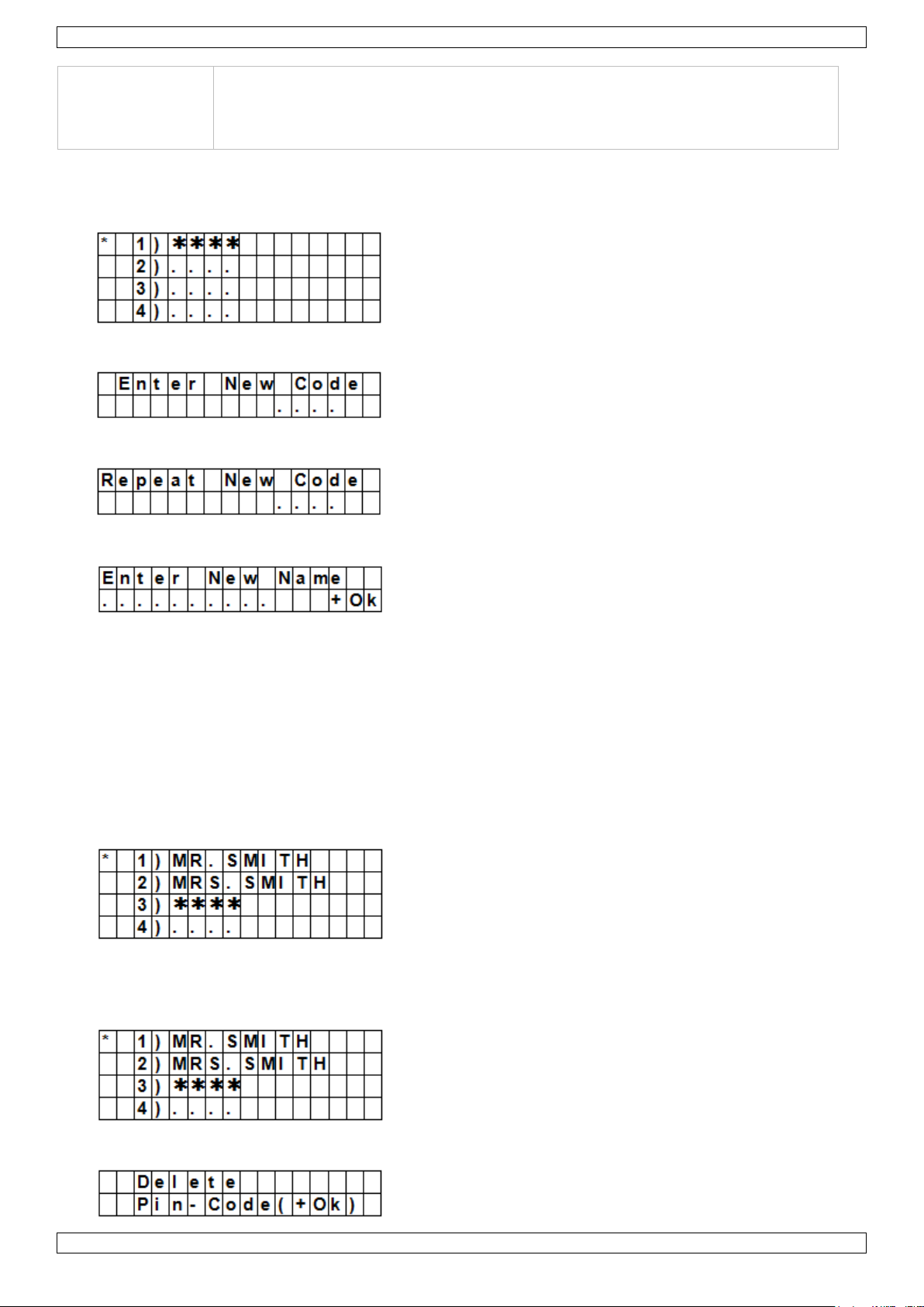
CTC1000
De code voor gebruiker 1 kan niet worden gewist.
Wordt naar de standaardcode teruggezet bij het resetten van het systeem (zie
hoofdstuk "Systeem resetten").
De pincode moet verschillend zijn van de mastercode.
Een pincode instellen
1. Om de optie te selecteren: ga naar de programmeermodus, ga naar "Gen. Settings", selecteer "Pin Code"
en druk op OK.
2. Selecteer het nummer van de pincode die u wilt instellen en druk op OK.
3. Toets een 4-cijferige code in en druk op OK.
4. Herhaal de code en druk op OK.
5. (optioneel) Geef een naam in voor de code.
o Deze naam verschijnt in de lijst met pincodes en helpt u om de code te herkennen.
o Voor meer informatie, zie 17 "Tekst ingeven".
o Laat dit veld leeg als u geen naam wilt gebruiken.
6. Druk op OK.
Opmerkingen
In de lijst met codes:
wordt een pincode zonder naam weergegeven met ****
wordt een niet-gedefinieerde pincode weergegeven met ••••
Een pincode wijzigen
1. Om de optie te selecteren: ga naar de programmeermodus, ga naar "Gen. Settings", selecteer "Pin Code"
en druk op OK.
2. Selecteer de code die u wilt instellen met behulp van de pijltjestoetsen en druk op OK.
V. 01 – 12/06/2013 44 ©Velleman nv
Page 45
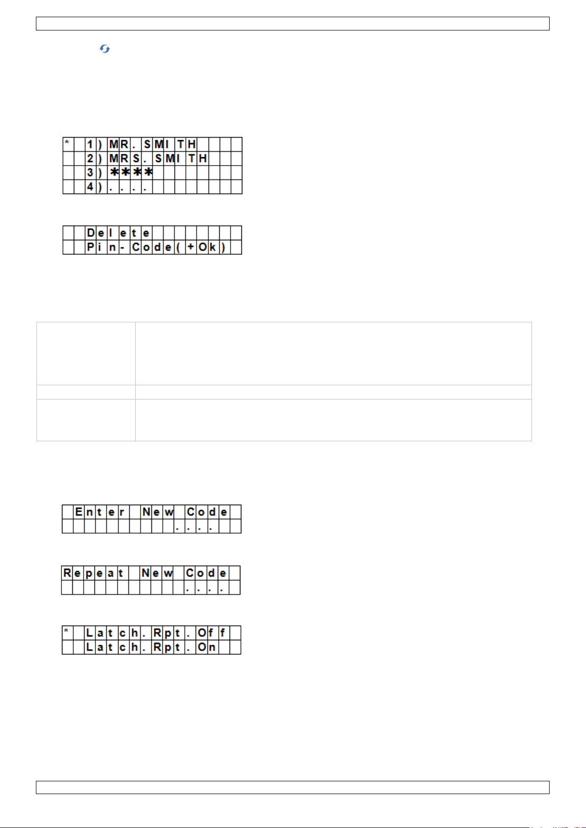
CTC1000
Gebruik
Wordt gebruikt om het alarmsysteem in of uit te schakelen voor een tijdelijke
gebruiker.
Eén keer geldig voor het in- of uitschakelen van het alarm.
Eenmaal gebruikt wordt de code automatisch gewist. U moet ze opnieuw instellen
indien nodig.
Standaardwaarde
Niet ingesteld
Eigenschappen
4 cijfers
Optioneel
Wordt gewist bij het resetten van het systeem (zie hoofdstuk "Systeem resetten")
3. Druk op .
4. Zie boven "De pincode instellen" To set a pin code.
Een pincode wissen
Pincode 1 kan niet worden gewist. Om een andere code te wissen:
1. Om de optie te selecteren: ga naar de programmeermodus, ga naar "Gen. Settings", selecteer "Pin Code"
en druk op OK.
2. Selecteer de code die u wilt wissen met behulp van de pijltjestoetsen en druk op OK.
3. Druk nogmaals op OK.
7.5 Temp. Code (tijdelijke code)
Een tijdelijke code instellen
1. Om de optie te selecteren: ga naar de programmeermodus, ga naar "Gen. Settings", selecteer "Temp.
Code" en druk op OK.
2. Toets een 4-cijferige code in en druk op OK.
3. Herhaal de code en druk op OK.
4. Stel de optie "Latch Rpt" ("latch key reporting", sleutelrapportering) in.
o Deze optie is enkel zichtbaar indien de "Latch Option"-optie op ON staat in de speciale instellingen.
Zie "Sleutelrapport" in hoofdstuk 8 "Special Settings" voor meer informatie.
5. Druk op OK.
Een tijdelijke code wijzigen
1. Om de optie te selecteren: ga naar de programmeermodus, ga naar "Gen. Settings", selecteer "Temp.
Code" en druk op OK.
V. 01 – 12/06/2013 45 ©Velleman nv
Page 46
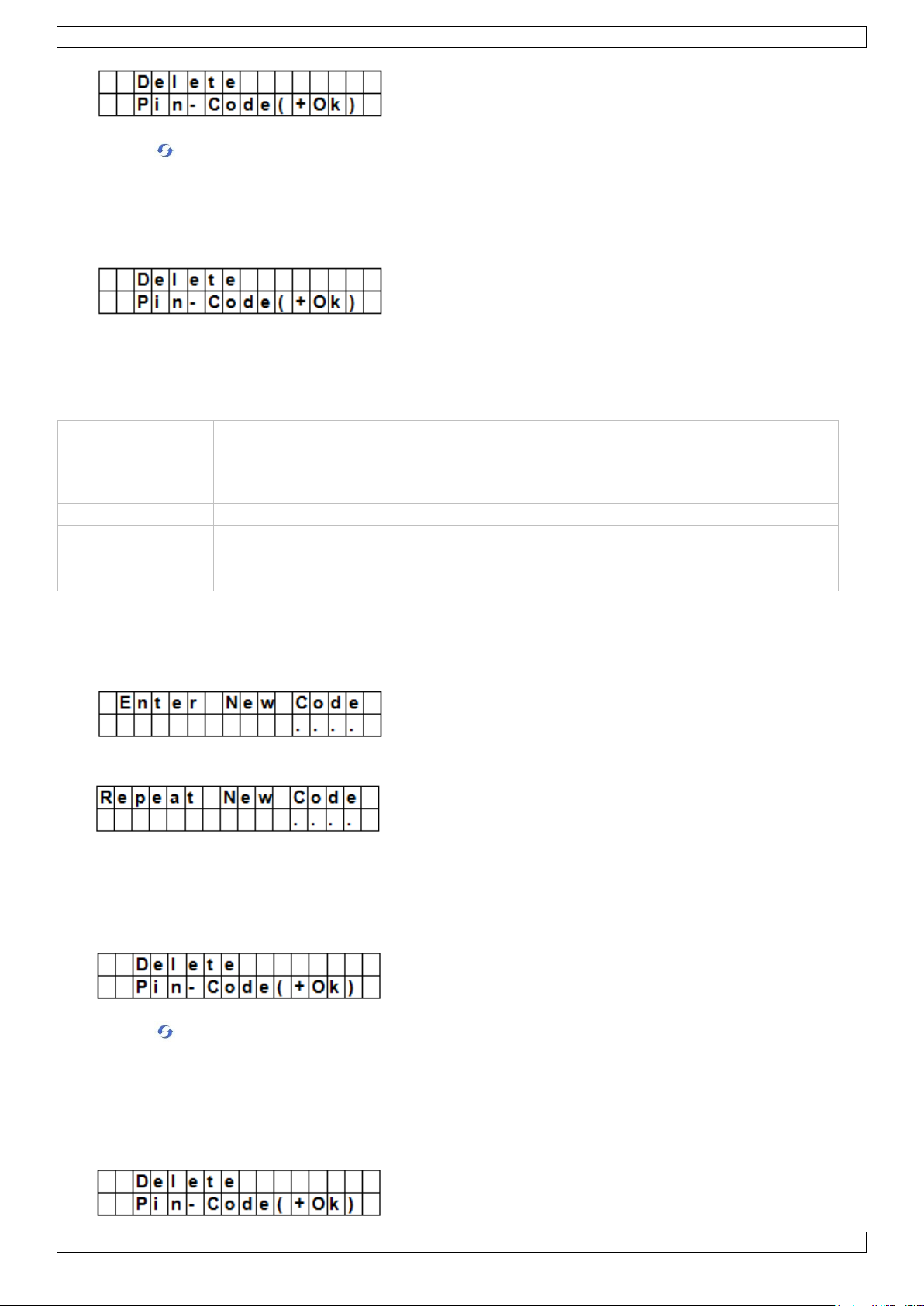
CTC1000
Gebruik
Kan worden gebruikt om het alarmsysteem in of uit te schakelen.
Als u wordt belaagd, kunt u de speciale dwangcode ingeven. Dit triggert een stil
alarm en verstuurt een bericht naar de ingestelde telefoonnummers.
U hoort geen sirene bij een dwangalarm.
Standaardwaarde
Niet ingesteld
Eigenschappen
4 cijfers
Optioneel
Wordt gewist bij het resetten van het systeem (zie hoofdstuk "Systeem resetten")
2. Druk op .
3. Zie boven "Een tijdelijke code instellen".
Een tijdelijke code wissen
1. Om de optie te selecteren: ga naar de programmeermodus, ga naar "Gen. Settings", selecteer "Temp.
Code" en druk op OK.
2. Druk nogmaals op OK.
7.6 Duress Code (dwangcode)
Een dwangcode instellen
1. Om de optie te selecteren: ga naar de programmeermodus, ga naar "Gen. Settings", selecteer "Duress
Code" en druk op OK.
2. Toets een 4-cijferige code in en druk op OK.
3. Herhaal de code en druk op OK.
Een dwangcode wijzigen
1. Om de optie te selecteren: ga naar de programmeermodus, ga naar "Gen. Settings", selecteer "Duress
Code" en druk op OK.
2. Druk op .
3. Toets een 4-cijferige code in en druk op OK.
4. Herhaal de code en druk op OK.
Een dwangcode wissen
1. Om de optie te selecteren: ga naar de programmeermodus, ga naar "Gen. Settings", selecteer "Duress
Code" en druk op OK.
V. 01 – 12/06/2013 46 ©Velleman nv
Page 47

CTC1000
Gebruik
Vereist samen met de pincode om toegang te krijgen tot de programmeermodus
van het toestel.
Standaardwaarde
1111
Eigenschappen
4 cijfers
Verplicht
Kan niet worden gewist
Wordt naar de standaardcode teruggezet bij het resetten van het systeem (zie
hoofdstuk "Systeem resetten").
De mastercode moet verschillend zijn van de pincodes.
2. Druk nogmaals op OK.
7.7 Master Code (mastercode)
Een mastercode instellen
1. Om de optie te selecteren: ga naar de programmeermodus, ga naar "Gen. Settings", selecteer "Master
Code" en druk op OK.
2. Toets een 4-cijferige code in en druk op OK.
3. Herhaal de code en druk op OK.
Een mastercode wijzigen
1. Om de optie te selecteren: ga naar de programmeermodus, ga naar "Gen. Settings", selecteer "Master
Code" en druk op OK.
2. Druk op .
3. Toets een 4-cijferige code in en druk op OK.
4. Herhaal de code en druk op OK.
Een mastercode wissen
1. Om de optie te selecteren: ga naar de programmeermodus, ga naar "Gen. Settings", selecteer "Master
Code" en druk op OK.
2. Druk nogmaals op OK.
7.8 A. Entry Time (tijd bij binnenkomen)
De optie "A. Entry Time" (away entry time) stelt de tijd in die u hebt om een pincode in te voeren na het
betreden van de woning.
Randvoorwaarden:
Alarmstatus: "away"
Detectietoestellen: deurcontact of PIR-detector ingesteld als "Entry" of "Away Entry" (zie 9.3).
Actie: het aftellen begint wanneer het deurcontact of de PIR-detector getriggerd wordt.
Indien de pincode niet wordt ingegeven binnen de ingestelde tijd, gaat een alarm af en wordt een bericht
verstuurd.
Beschikbare timer-opties: "Disable" (uitschakelen, het alarm zal onmiddellijk afgaan) of met vertraging van
10 tot 70 seconden.
Standaard: 20 seconden.
Om deze optie te selecteren: ga naar de programmeermodus, ga naar "Gen. Settings", selecteer "A. Entry
Time" en druk op OK.
7.9 A. Exit Time (tijd bij buitengaan)
V. 01 – 12/06/2013 47 ©Velleman nv
Page 48
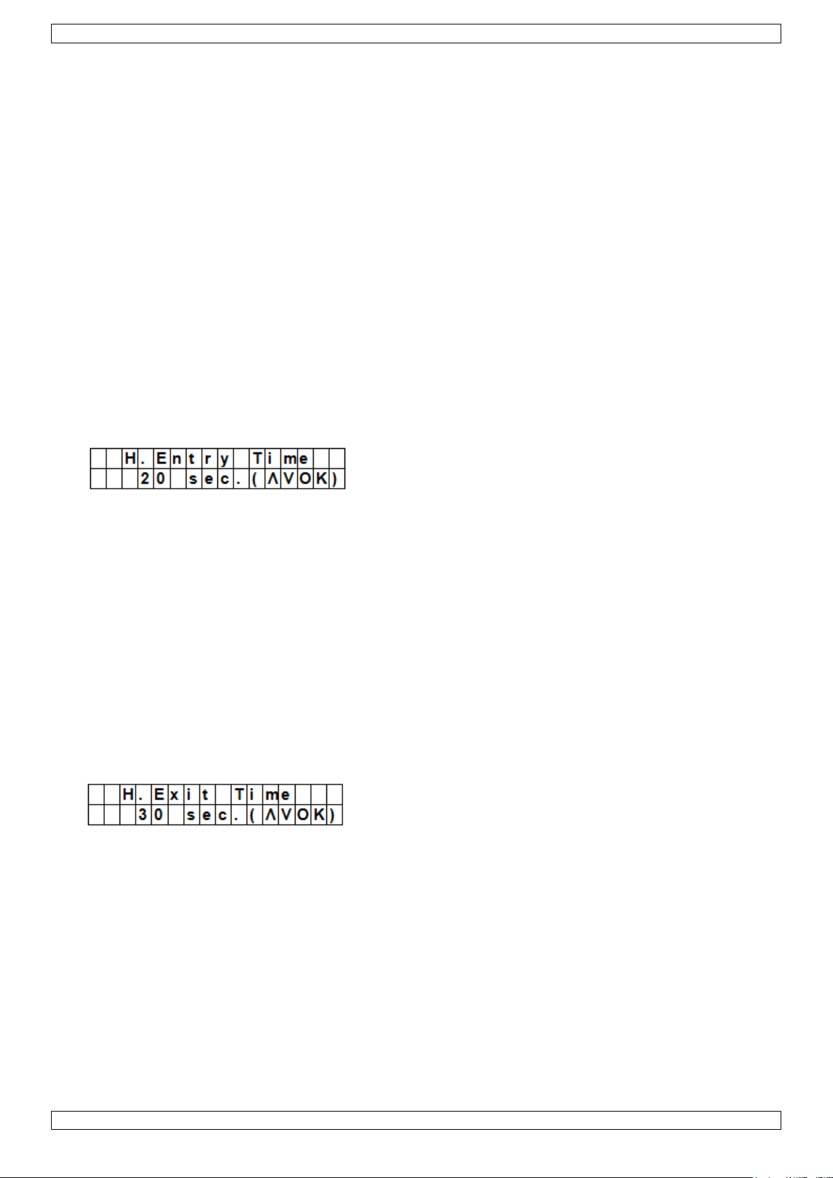
CTC1000
De optie "A. Exit Time" (away exit time) stelt de tijd in die u hebt om de woning te verlaten nadat het alarm
"away" ingeschakeld werd met het controlepaneel, een afstandsbediening of een bedieningsconsole.
Randvoorwaarden:
Alarmstatus: ingesteld op "away" met behulp van het controlepaneel, een afstandsbediening of een
bedieningsconsole
Actie: het aftellen begint wanneer het alarm wordt ingesteld op "away" met behulp van het controlepaneel,
een afstandsbediening of een bedieningsconsole.
Beschikbare timer-opties: "Disable" (uitschakelen, geen timer bij het buitengaan) of met vertraging van 10
tot 70 seconden.
Standaard: 30 seconden.
Om deze optie te selecteren: ga naar de programmeermodus, ga naar "Gen. Settings", selecteer "A. Exit
Time" en druk op OK.
Opmerkingen
Wanneer u op de knop "Alarm inschakelen" drukt op de afstandsbediening, zal het aftellen opnieuw
beginnen.
Wanneer u op de knop "Alarm uitschakelen" drukt op de afstandsbediening, zal de teller stoppen en wordt
het alarm uitgeschakeld.
Wanneer u een pincode ingeeft op het controlepaneel, zal de teller stoppen en wordt het alarm
uitgeschakeld.
7.10 H. Entry Time
De optie "H. Entry Time" (home entry time) stelt de tijd in die u hebt om de woning te betreden wanneer het
systeem in "Home"-modus staat.
Randvoorwaarden:
Alarmstatus: "Home"-modus
Detectietoestellen: deurcontact of PIR-detector ingesteld op "Entry" of "Home Access" (zie 9.3).
Actie: het aftellen begint wanneer het deurcontact of de PIR-detector getriggerd wordt.
Indien de pincode niet wordt ingegeven binnen de ingestelde tijd, gaat een alarm af en wordt een bericht
verstuurd.
Beschikbare timer-opties: "Disable" (uitschakelen, het alarm zal onmiddellijk afgaan) of met vertraging van
10 tot 70 seconden.
Standaard: 20 seconden.
Om deze optie te selecteren: ga naar de programmeermodus, ga naar "Gen. Settings", selecteer "H. Entry
Time" en druk op OK.
7.11 H. Exit Time (tijd bij buitengaan voor home-alarm)
De optie "H. Entry Time" (home entry time) stelt de tijd in die u hebt om de woning te verlaten wanneer het
systeem in "Home"-modus staat.
Randvoorwaarden:
Alarmstatus: ingesteld op "away" via het controlepaneel, een afstandsbediening of een bedieningsconsole
Actie: het aftellen begint wanneer het alarm wordt ingesteld op "away" met behulp van het controlepaneel,
een afstandsbediening of een bedieningsconsole.
Beschikbare timer-opties: "Disable" (uitschakelen, geen timer bij het buitengaan) of met vertraging van 10
tot 70 seconden.
Standaard: 30 seconden.
Om deze optie te selecteren: ga naar de programmeermodus, ga naar "Gen. Settings", selecteer "H. Exit
Time" en druk op OK.
Opmerkingen
Wanneer u drukt op de "Home"-knop op de afstandsbediening, zal het aftellen opnieuw beginnen.
V. 01 – 12/06/2013 48 ©Velleman nv
Page 49

CTC1000
Wanneer u op de knop "Alarm uitschakelen" drukt op de afstandsbediening, zal de teller stoppen en wordt
het alarm uitgeschakeld.
Wanneer u een pincode ingeeft op het controlepaneel, zal de teller stoppen en wordt het alarm
uitgeschakeld.
7.12 Door Chime (deurbel)
De optie "Door Chime" schakelt de deurbel in of uit wanneer een deurcontact of PIR-detector geactiveerd wordt
in "Alarm Off"-modus.
Randvoorwaarden:
Alarmstatus: "Off"
Detectietoestellen: deurcontact of PIR-detector ingesteld als "Entry" of "Away Entry" (zie 9.3).
Actie: Het controlepaneel laat een bel weerklinken zolang het deurcontact of de PIR-detector geactiveerd is
in "Alarm Off"-modus.
Standaard "Off".
Om deze optie te selecteren: ga naar de programmeermodus, ga naar "Gen. Settings", selecteer "Door
Chime" en druk op OK.
7.13 Time (klok)
Met de optie "Time" kunt u de huidige tijd instellen.
1. Om deze optie te selecteren: ga naar de programmeermodus, ga naar "Gen. Settings", selecteer "Time" en
druk op OK.
2. Gebruik de pijltjestoetsen (omhoog en omlaag) om de uren in te stellen en druk op OK.
3. Gebruik de pijltjestoetsen (omhoog en omlaag) om de minuten in te stellen en druk op OK.
7.14 Date (datum)
Met de optie "Date" kunt u de huidige datum instellen.
1. Om deze optie te selecteren: ga naar de programmeermodus, ga naar "Gen. Settings", selecteer "Date" en
druk op OK.
2. Gebruik de pijltjestoetsen (omhoog en omlaag) om de maand in te stellen en druk op OK.
3. Gebruik de pijltjestoetsen (omhoog en omlaag) om de dag in te stellen en druk op OK.
7.15 Panel Siren (paneelsirene)
Met optie "Panel Sirene" kunt u de sirene op het controlepaneel in- of uitschakelen wanneer er een alarm
optreedt.
1. Om deze optie te selecteren: ga naar de programmeermodus, ga naar "Gen. Settings", selecteer "Panel
Siren" en druk op OK.
2. Gebruik de pijltjestoetsen om de optie te selecteren en druk op OK.
8. Speciale instellingen
Om de speciale instellingen te beheren:
Ga naar de programmeermodus en ga naar "Spc. Settings".
V. 01 – 12/06/2013 49 ©Velleman nv
Page 50

CTC1000
Alarm Length (alarmduur)
Instelling alarmduur van de ingebouwde sirene wanneer een alarm geactiveerd wordt.
De beschikbare opties zijn: "Disable" (uitschakelen, het alarm zal niet afgaan) of een duur van 1 tot 15
minuten.
Standaard: 3 minuten.
Opmerkingen
Als u "Disable" (uitschakelen) kiest en het controlepaneel ontvangt een alarmsignaal, gaat geen enkele
sirene af: noch de paneelsirene, noch de interne en externe sirenes.
Als de alarmduur van de buitensirene langer is dan de alarmduur van het controlepaneel, geeft het systeem
prioriteit aan het controlepaneel. Voorbeeld: de alarmduur voor de sirene is ingesteld op 3 minuten en de
alarmduur van het controlepaneel op 1 minuut. Beide sirenes stoppen na 1 minuut, maar de led van de
buitensirene blijft gedurende 3 minuten flitsen.
A. Exit Sound (geluid bij buitengaan)
(= geluid bij buitengaan)
Pieptoon voor de Away Exit Timer in- of uitschakelen
A. Entry Sound (geluid bij binnenkomen)
(= geluid bij binnenkomen)
Pieptoon voor de Away Entry Timer in- of uitschakelen
H. Exit Sound
(= geluid bij buitengaan voor home-alarm)
Pieptoon in- of uitschakelen bij het verlaten van de woning in "Home"-modus.
V. 01 – 12/06/2013 50 ©Velleman nv
Page 51

CTC1000
H. Entry Sound
(= geluid bij binnenkomen voor home-alarm)
Pieptoon in- of uitschakelen bij het betreden van de woning in "Home"-modus.
Siren Delay (sirenevertraging)
Instellen van de tijd voordat de sirene geactiveerd wordt na een inbraakalarm.
De beschikbare opties zijn: "Off" (geen geluid) en met vertraging van 1 tot 10 minuten.
Standaard: "Off" (geen geluid).
Opmerkingen
De optie sirenevertraging is enkel van toepassing bij inbraakalarm. Andere alarmen worden niet vertraagd:
o Brandalarm
o Wateralarm
o Paniekalarm
o Medisch noodgeval
o Sabotagealarm
o Gsm-storing
Het alarmbericht wordt onmiddellijk verstuurd, zelfs al is het hoorbare alarm vertraagd.
Verification (verificatie)
Sequentiële alarmverificatie.
Sequentiële verificatie aan
Als "Seq. Verif." ingesteld staat op "On" en
Indien er meer dan één sensor (deurcontact of PIR-detector) is ingesteld op "Burglar":
o Als de eerste sensor getriggerd wordt, dan zal het controlepaneel een sms sturen met "Burglar".
o Als de tweede sensor binnen 30 minuten getriggerd wordt, zal het controlepaneel een sms sturen met
"Alarm confirm".
Sequentiële verificatie uit
Als "Seq. Verif." ingesteld staat op "Off", dan zal het controlepaneel enkel een sms sturen met "Burglar".
Final Door (laatste deur)
Als de optie "Final Door" ingesteld staat op "On" en
Als het alarmsysteem ingesteld staat op "Away Arming" en
een deurcontact ingesteld is als ingangstoestel
V. 01 – 12/06/2013 51 ©Velleman nv
Page 52

CTC1000
Optie
Functie
Away Arm Only
Het controlepaneel geeft enkel in de "Away"-modus een plaatselijk
alarmsignaal en stuurt een bericht naar de centrale.
Als het alarm werkt in Home of "Alarm Off"-modus, stuurt het
controlepaneel een bericht, maar de sirene gaat niet af.
Normal
Het controlepaneel geeft in alle modi een plaatselijk alarmsignaal en
Zodra het deurcontact gedetecteerd wordt als gesloten, zal het systeem automatisch inschakelen zelfs al is het
aftellen nog niet afgelopen.
Interference (storing)
Detectie signaalblokkering in- of uitschakelen
Wanneer "Detection" op "On" staat en telkens het signaal langer dan 30 seconden geblokkeerd wordt, dan
wordt deze fout geregistreerd en gemeld aan de centrale meldkamer. De fout verschijnt ook op de display
om de gebruiker te waarschuwen.
Wanneer "Dectection" op "Off" staat, zal het controlepaneel de storingstatus niet nagaan.
RC Ent E (= remote controller entry enabled)
Deze functie verhindert dat het alarm uitgeschakeld wordt met een afstandsbediening zonder eerst een deur te
ontgrendelen, bv. indien de afstandsbediening gestolen is.
Om de functie te gebruiken:
moet u eerst een toegangstoestel activeren dat het alarmsysteem kan uitschakelen.
Indien de optie "RC Ent E" ingesteld staat op "On":
kan een afstandsbediening het alarmsysteem uitschakelen zonder eerst een deur te ontgrendelen.
Mobility (gsm-timer)
Deze optie (de)activeert de gsm-timer en stelt een aftelperiode in. Beschikbare opties zijn "Disable"
(uitschakelen), 4 uur, 8 uur en 12 uur.
Wanneer de gsm-timer actief is, wordt de programmeerde tijdsduur afgeteld. Wanneer de timer stopt zonder te
resetten, wordt een bericht gestuurd naar de geprogrammeerde telefoonnummers.
Wanneer de gsm-timer ingesteld is op een bepaalde tijdsduur, stuurt het controlepaneel berichten naar de
geprogrammeerde telefoonnummers als de timer op nul staat, tenzij de teller gereset wordt door één van
de volgende acties:
o In "Home"-modus: wanneer eender welk "Home Omit"-, deurcontact- of bewegingsalarm wordt
getriggerd, of wanneer eender welke toets op het controlepaneel wordt ingedrukt;
o Als het alarm uitgeschakeld is: wanneer eender welk deurcontact- of bewegingsalarm (behalve 24 uur,
brand, medisch noodgeval of water) wordt getriggerd, of wanneer eender welke toets op het
controlepaneel wordt ingedrukt.
Wanneer het systeem is ingesteld op "Away Arm" (ingeschakeld, niet thuis), stopt de timer automatisch.
Wanneer the systeem in de modus "Home Arm" gaat of uitgeschakeld wordt (Disarm), begint de timer
automatisch opnieuw.
Sabotagealarm
Instelling sirene wanneer er het systeem gesaboteerd wordt.
V. 01 – 12/06/2013 52 ©Velleman nv
Page 53

CTC1000
stuurt een bericht naar de meldkamer.
Opmerkingen
Onafhankelijk van de sirene-instelling zal het controlepaneel in alle
modi het sabotagealarm melden via een sms naar het eerste
telefoonnummer.
Als de sabotage hersteld is, zal het paneel dit ook melden via een sms
naar het eerste telefoonnummer.
Opmerkingen
Als sleutelrapportering is uitgeschakeld ("Latch" staat op "Off"), dan
verdwijnt de functie uit het programmeermenu (zie 7.5Temp. Code
(tijdelijke code)).
Als sleutelrapportering is ingeschakeld ("Latch" staat op "on"), worden
alle in- en uitschakelingen van alle gebruikers en afstandsbedieningen
standaard geregistreerd en doorgegeven aan de centrale.
Om het sms-rapport te ontvangen, stelt u het eerste telefoonnummer
in als sms-rapport.
Sleutelrapport
Het sleutelrapport registreert alle in- en uitschakelingen door alle gebruikers op het controlepaneel en via
afstandsbediening.
Supervision (supervisie)
Deze optie (de)activeert de supervisiefunctie. Als deze optie is ingesteld op "ON", kan het controlepaneel
controlesignalen ontvangen van de randapparaten om na te gaan of deze goed werken.
Opties zijn: "Disable" (uitschakelen), 8 uur, 12 uur en 24 uur.
Warning Beep (waarschuwingstoon)
(De)activeert de waarschuwingstoon wanneer het controlepaneel een foutmelding weergeeft.
Deze waarschuwingstoon stopt wanneer de foutmelding gelezen is.
GSM-band
Afhankelijk van de netwerkinstellingen van de netbeheerder stelt u de gsm-band in. Neem contact op met uw
locale netbeheerder voor de juiste instelling.
Stop
Selecteer "Stop" en druk op OK om de instellingen te bewaren en terug te keren naar de vorige menuoptie.
V. 01 – 12/06/2013 53 ©Velleman nv
Page 54

CTC1000
9. Apparaten beheren
Via het menu "Devices+/-", beheert (toevoegen, instellen, wijzigen, verwijderen) u alle aangesloten apparaten
zoals deurcontacten, PIR-detectoren, sirenes, enz. in maximaal 30 zones.
Installatievolgorde
Het systeem beschouwt binnen- en buitensirenes en universele ontvangers als aanvullende apparaten. Voor u
zo'n aanvullend apparaat toevoegt, moet u minstens één ander apparaat toevoegen (een deurcontact, PIRdetector of afstandsbediening).
9.2 Een apparaat toevoegen
Om de functie te gebruiken:
1. Ga naar de programmeermodus, ga naar "Devices+/-", selecteer "Add device" en druk op OK.
2. Druk op de testknop van het apparaat dat u wilt toevoegen.
3. Als het controlepaneel het apparaat detecteert, verschijnt het type apparaat op het scherm:
Mogelijke apparaten zijn:
Door Contact (deurcontact)
PIR Sensor (bewegingsdetector)
External PIR Sensor (externe bewegingsdetector)
Remote Controller (afstandsbediening)
Remote Keypad (bedieningsconsole)
Water Sensor (waterdetector)
Outdoor Siren (buitensirene)
Universal Receiver (universele ontvanger)
4. Druk op OK om te bevestigen.
Het controlepaneel toont dan de ongebruikte beveiligingszones (max. 30).
5. Gebruik de pijltjestoetsen om het nummer te kiezen van de zone waaraan u het apparaat wilt toewijzen en
druk op OK.
De procedure is nu verder afhankelijk van het type apparaat dat u wilt toevoegen.
6. Selecteer "Stop" en druk op OK om de instellingen te bewaren en terug te keren naar de vorige menuoptie.
V. 01 – 12/06/2013 54 ©Velleman nv
Page 55

CTC1000
Opmerkingen
Een foutmelding verschijnt als u probeert een sensor toe te voegen die reeds geregistreerd is.
Om dit apparaat toch toe te voegen, moet u het eerst verwijderen (zie 9.5 "Een apparaat verwijderen").
Druk op om de procedure te annuleren.
Afhankelijk van het type apparaat dat u wilt toevoegen, verschijnen er verschillende schermen voor de
bijhorende instellingen.
Een deurcontact toevoegen
1. Gebruik de pijltjestoetsen om een werkmodus te selecteren en druk op OK.
Voor meer informatie over de beschikbare werkmodi, zie 9.3.
2. Voorzie een naam voor de zone.
Laat dit veld leeg als u geen naam wilt gebruiken.
3. Druk op OK om de installatie te bevestigen.
4. Druk opnieuw op OK om te beëindigen.
Een PIR-detector toevoegen
We gaan ervan uit dat u reeds een zonenummer hebt toegewezen (zie 9.2):
1. Gebruik de pijltjestoetsen om een werkmodus te selecteren en druk op OK.
Voor meer informatie over de beschikbare werkmodi, zie 9.3.
2. Voorzie een naam voor de zone.
Laat dit veld leeg als u geen naam wilt gebruiken.
V. 01 – 12/06/2013 55 ©Velleman nv
Page 56

CTC1000
3. Druk op OK om de installatie te bevestigen.
4. Druk opnieuw op OK om te beëindigen.
Een externe PIR-detector toevoegen
We gaan ervan uit dat u reeds een zonenummer hebt toegewezen (zie 9.2):
1. Gebruik de pijltjestoetsen om een PIR-type te selecteren en druk op OK.
o Regular: apparaat wordt toegevoegd als een gewone PIR
o External: apparaat wordt toegevoegd als een externe PIR.
2. Gebruik de pijltjestoetsen om een werkmodus te selecteren en druk op OK.
Voor meer informatie over de beschikbare werkmodi, zie 9.3.
3. Voorzie een naam voor de zone.
Laat dit veld leeg als u geen naam wilt gebruiken.
Voor meer informatie over het invoeren van tekst, zie 17.
4. Druk op OK om de installatie te bevestigen.
5. Druk opnieuw op OK om te beëindigen.
Een afstandsbediening toevoegen
We gaan ervan uit dat u reeds een zonenummer hebt toegewezen (zie 9.2):
1. Gebruik de pijltjestoetsen om de gewenste optie voor de afstandsbediening te kiezen.
o Personal att: het controlepaneel geeft een alarm voor een aanval op personen als de paniekknop
gedurende 3 seconden wordt ingedrukt, of twee keer binnen de 3 seconden.
o Medical Emg: het controlepaneel geeft een alarm voor een medisch noodgeval als de paniekknop
gedurende 3 seconden wordt ingedrukt, of twee keer binnen de 3 seconden.
2. Gebruik de pijltjestoetsen om een werkmodus te selecteren en druk op OK.
Voor meer informatie over de beschikbare werkmodi, zie 9.3.
3. Voorzie een naam voor de zone.
Laat dit veld leeg als u geen naam wilt gebruiken.
Voor meer informatie over het invoeren van tekst, zie 17.
4. Druk op OK om de installatie te bevestigen.
V. 01 – 12/06/2013 56 ©Velleman nv
Page 57

CTC1000
Modus
Systeemstatus
Werking van het apparaat
Burglar
Wanneer het toestel zich in "Away Arm/Home Arm-"modus bevindt, of tijdens de
ingangsvertragings- of
uitgangsvertragingsperiode.
Wordt een deur-/venstercontact getriggerd,
dan wordt onmiddellijk een inbraakalarm
ingeschakeld.
Home Omit
Wanneer het toestel zich in "Away Arm"modus bevindt (incl. Away Arm Entry)
Wordt een Home Omit-deurcontact getriggerd,
dan wordt onmiddellijk een inbraakalarm
ingeschakeld.
Wanneer het toestel zich in Home Omitdeurcontact getriggerd wordt
Het controlepaneel zal niet reageren
Tijdens de ingangs- of
uitgangsvertragingsperiode, wanneer een
Home Omit-deurcontact getriggerd wordt
Het controlepaneel zal niet reageren
Home Access
Wanneer het toestel zich in "Away Arm"modus bevindt
Wordt een Home Access-deurcontact
getriggerd, dan wordt onmiddellijk een
inbraakalaarm ingeschakeld.
Wanneer het toestel zich in "Home Arm"modus bevindt
Wordt een Home Access-deurcontact
getriggerd, dan start het controlepaneel de
ingangsvertragingsperiode, waarbij u genoeg
tijd hebt om het systeem uit te schakelen.
Tijdens de vertraging bij het
binnenkomen of buitengaan
Wordt een Home Acces-deurcontact getriggerd,
dan reageert het controlepaneel niet
Delay
(vertraging)
Wanneer het toestel zich in "Away Arm- /
Home Arm"-modus bevindt
Wordt een Delay-deurcontact getriggerd, dan
wordt onmiddellijk een inbraakalarm
ingeschakeld
Tijdens de vertraging bij het
binnenkomen of buitengaan
Wordt een Delay Zone-deurcontact getriggerd,
dan reageert het controlepaneel niet
Entry
(binnenkomen)
Wanneer het toestel zich in "Away Arm- /
Home Arm"-modus bevindt
Wordt een Entry-deurcontact getriggerd, dan
start het controlepaneel een
ingangsvertragingsperiode, waarbij u
voldoende tijd hebt om het systeem uit te
schakelen
5. Druk opnieuw op OK om te beëindigen.
Een bedieningsconsole of waterdetector toevoegen
De installatie is gelijkaardig voor deze types apparaten.
We gaan ervan uit dat u reeds een zonenummer hebt toegewezen (zie 9.2):
1. Voorzie een naam voor de zone.
Laat dit veld leeg als u geen naam wilt gebruiken.
Voor meer informatie over het invoeren van tekst, zie 17.
2. Druk op OK.
3. Druk opnieuw op OK om te beëindigen.
Een aanvullend apparaat toevoegen (Program Siren menu)
Het systeem beschouwt binnen- en buitensirenes en universele ontvangers als aanvullende apparaten. Voor u
zo'n aanvullend apparaat toevoegt, moet u minstens één ander apparaat toevoegen (detector of
bedieningsconsole). Het systeem toont een foutmelding als dit nog niet gebeurd is.
1. Ga naar de programmeermodus, na naar "Devices+/-", selecteer "Program Siren", daarna "Learn Siren" en
druk op OK.
2. Zet het apparaat dat u wilt toevoegen in leermodus (zie de gebruikshandleiding van het apparaat).
3. Druk op OK.
Het controlepaneel laat een lange pieptoon horen en stuurt tegelijkertijd de programmeercode door naar
alle apparaten. De buitensirene moet antwoorden door de sirene en het stroboscooplicht kortstondig te
laten werken. De led op de universele ontvanger licht op gedurende 3 seconden.
9.3 Een apparaat toevoegen: overzicht van werkmodi
Het overzicht hieronder toont de mogelijke modi voor alle apparaten. Welke modi werkelijk beschikbaar zijn,
hangt af van het type apparaat dat u toevoegt.
V. 01 – 12/06/2013 57 ©Velleman nv
Page 58

CTC1000
Modus
Systeemstatus
Werking van het apparaat
Na de vertragingsperiode, en als er geen
juiste pincode is ingegeven om het
systeem uit te schakelen
Het controlepaneel schakelt van 30 seconden
een inbraakalarm in
Wanneer het toestel zich in "Alarm Off"modus bevindt
Wordt een Entry-deurcontact getriggerd, dan
weerklinkt "Ding-Dong" (indien ingesteld).
Away Entry
(binnenkomen
na afwezigheid)
Wanneer het toestel zich in "Away Arm"modus bevindt
Wordt een Away Entry-deurcontact getriggerd,
dan start het controlepaneel een
vertragingsperiode waardoor u voldoende tijd
hebt om het systeem uit te schakelen.
Na de vertragingsperiode, en als er geen
juiste pincode is ingegeven om het
systeem uit te schakelen
Het controlepaneel schakelt na 30 seconden
een inbraakalarm in
Wanneer het toestel zich in "Alarm Off"modus bevindt
Wordt een Entry-deurcontact getriggerd, dan
weerklinkt "Ding-Dong" (indien ingesteld).
Wanneer het toestel zich in "Home Arm"modus bevindt.
Wordt een Away Entry-deurcontact getriggerd,
dan reageert het controlepaneel niet.
Tijdens de vertraging bij het
binnenkomen of buitengaan
Wordt een Away Entry-deurcontact getriggerd,
dan reageert het controlepaneel niet
24 Hour (24
uur)
Niet van toepassing
Dit deurcontact is constant actief en moet niet
in- of uitgeschakeld worden
Fire (brand)
Niet van toepassing
Dit deurcontact is constant actief en moet niet
in- of uitgeschakeld worden
Medical Emg
(medisch
noodgeval)
Niet van toepassing
Dit deurcontact is constant actief en moet niet
in- of uitgeschakeld worden
Water
Niet van toepassing
Dit deurcontact is constant actief en moet niet
in- of uitgeschakeld worden
9.4 Een apparaat wijzigen
De procedure is afhankelijk van het type apparaat dat u wilt wijzigen.
Een deurcontact – PIR-detector – afstandsbediening wijzigen
Ga naar de programmeermodus, ga naar "Devices+/-", selecteer "Edit devices" en druk op OK.
De display toont alle beschikbare apparaten.
1. Gebruik de pijltjestoetsen om een apparaat te selecteren en druk op OK.
U kunt nu de instellingen van het apparaat wijzigen. Om deze stap over te slaan, druk op .
2. Gebruik de pijltjestoetsen om een optie te kiezen en druk op OK.
V. 01 – 12/06/2013 58 ©Velleman nv
Page 59

CTC1000
3. Druk op OK om te bevestigen.
U kunt nu de naam van het apparaat wijzigen. Om deze stap over te slaan, druk op . Om verder te gaan,
druk op OK.
4. Geef een zonenaam in en druk op OK.
De lijst met apparaten verschijnt weer op de display. Gebruik de pijltjestoetsen om een ander apparaat te
selecteren of druk op .
Een bedieningsconsole – waterdetector wijzigen
1. Ga naar de programmeermodus, ga naar "Devices+/-", selecteer "Edit devices" en druk op OK.
De display toont alle beschikbare apparaten.
2. U kunt nu de naam van het apparaat wijzigen.
3. Geef een zonenaam in en druk op OK.
De lijst met apparaten verschijnt weer op de display. Gebruik de pijltjestoetsen om een ander apparaat te
selecteren of druk op .
9.5 Een apparaat verwijderen
1. Ga naar de programmeermodus, ga naar "Devices+/-", selecteer "Remove device" en druk op OK.
Het systeem toont alle beschikbare apparaten.
2. Gebruik de pijltjestoetsen om een apparaat te selecteren en druk op OK.
Voor meer informatie over de beschikbare werkmodi, zie 9.3.
3. Druk opnieuw op OK om te bevestigen.
9.6 Program Siren menu – andere mogelijkheden
Learn Siren
Verbind eerst een binnen- of buitenalarm of een universele ontvanger met het controlepaneel via de
programmeermodus zodat deze met elkaar kunnen communiceren.
Voor u een extra toestel toevoegt, programmeer eerst één van de volgende toestellen: PIR-bewegingsdetector
of deur-/venstercontact. Installeer geen sirene, geen alarm en geen DIP-schakelaar.
Voor u zo'n aanvullend apparaat toevoegt, moet u minstens één ander apparaat toevoegen (een deurcontact,
PIR-detector of afstandsbediening).
Een buiten- of binnensirene toevoegen:
V. 01 – 12/06/2013 59 ©Velleman nv
Page 60
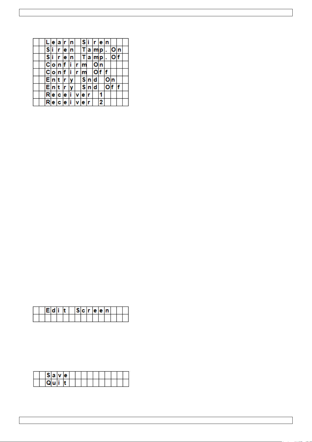
CTC1000
1. Zet het apparaat of de apparaten die u wilt toevoegen in leermodus.
2. Ga naar de programmeermodus, na naar "Devices+/-", selecteer "Program Siren" en druk op OK.
3. Selecteer "Learn Siren" met de pijltjestoetsen en druk op OK.
o Het controlepaneel laat een lange pieptoon horen en stuurt tegelijkertijd de leercode naar alle
toestellen.
o De buitensirene schakelt de sirene en de stroboscooplamp onmiddellijk in.
4. Zorg ervoor dat deze aanvullende apparaten niet in leermodus staan. Het toevoegen is voltooid.
Siren Tamp. On - Siren Tamp. Off (sirene met sabotageschakelaar in- of uitschakelen)
De sabotageschakelaar van de buitensirene kan met de afstandsbediening in- en uitgeschakeld worden.
Deze functie is zeer praktisch wanneer u de batterijen van de sirene moet vervangen.
Om de sabotageschakelaar uit te schakelen: selecteer "Siren Tamp.Off" en druk op OK.
De sabotageschakelaar van alle aangesloten sirenes wordt gelijktijdig uitgeschakeld.
Om de sabotageschakelaar in te schakelen: selecteer "Siren Tamp.Off" en druk op OK.
De sabotageschakelaar van alle aangesloten sirenes wordt gelijktijdig ingeschakeld.
Confirm On - Confirm Off (bevestigingsgeluid in- of uitschakelen)
Is deze optie ingeschakeld, dan weerklinkt een bevestigingsgeluid (buitensirene) bij het in- of uitschakelen
van het systeem.
Is deze optie uitgeschakeld, dan weerklinkt een bevestigingsgeluid (buitensirene) bij het in- of uitschakelen
van het systeem.
Selecteer "Confirm ON" of "Confirm Off" en druk op OK.
Entry Snd On - Entry Snd Off (waarschuwingssignaal in- of uitschakelen)
Is deze optie in- of uitgeschakeld, dan weerklinkt een of geen waarschuwingssignaal (sirene) bij het betreden
van de woning.
Selecteer "Entry Snd ON" of "Entry Snd OFF" en druk op OK.
10. Andere configuratiefuncties
SMS Editor
Het controlepaneel wijzigt het sms-bericht, dat bij een alarmevent naar de mobiele telefoon gestuurd wordt.
1. Ga naar de programmeermodus en selecteer "SMS Editor" in het menu.
Het venster om het bericht te wijzigen, wordt weergegeven.
2. Geef een sms-bericht in (max. 16 x 4 tekens).
Voor meer informatie over het invoeren van tekst, zie 17.
3. Druk op OK.
4. Selecteer "Save' en druk op OK om te bevestigen.
V. 01 – 12/06/2013 60 ©Velleman nv
Page 61
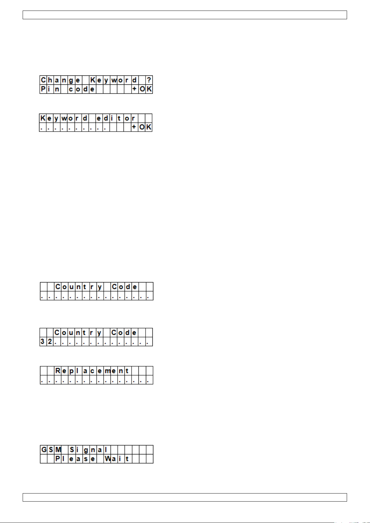
CTC1000
SMS Keyword
Het controlepaneel ondersteunt bevelen die met een mobiele telefoon naar het systeem gestuurd worden. U
moet eerst het "SMS keyword" ingeven, voor u een bevel kunt sturen. Het standaard sleutelwoord komt
overeen met de standaard pincode (zie 7.4 Pin code).
De pincode voor bevelen wijzigen
1. Ga naar de programmeermodus, selecteer "SMS Keyword" in het menu en druk op OK.
2. Toets een 4-cijferige code in en druk op OK.
3. Herhaal de code en druk op OK.
Country Code
De formaatweergave van het telefoonnummer (met of zonder landcode) varieert en hangt van gsm-provider af.
Als uw gsm telefoonnummers weergeeft zonder de landcode, dan kunt u dit hoofdstuk overslaan.
Als uw gsm telefoonnummers weergeeft met de landcode (bijvoorbeeld +321234567890), moet u de instelling
van het controlepaneel wijzigen.
Vraag dit aan uw netverdeler of test zelf als volgt:
1. Plaats de SIM-kaart die u zal gebruiken voor het controlepaneel in een gsm.
2. Schakel de mobiele telefoon in.
3. Controleer of het nummer niet is toegewezen aan een andere contactpersoon in uw telefoon.
4. Stuur een sms naar hetzelfde nummer.
o Als uw gsm telefoonnummers weergeeft zonder de landcode (bijvoorbeeld 01234567890), dan kunt u
dit hoofdstuk overslaan.
o Als uw gsm telefoonnummers weergeeft met de landcode (bijvoorbeeld +321234567890), ga dan als
volgt te werk.
5. Op het controlepaneel, ga naar de programmeermodus, ga naar "Country Code" en druk op OK.
6. Geef de landcode van uw land in.
Bijvoorbeeld: Is het weergegeven nummer op de telefoon + 31234567890, geef dan 32 in (zonder '+').
7. Druk op OK.
8. Druk op de toets 0.
9. Druk op OK om te beëindigen.
GSM Signal
Met deze optie kunt u de signaalsterkte controleren.
1. Op het controlepaneel, ga naar de programmeermodus, ga naar "GSM Signal" en druk op OK.
Het systeem geeft de signaalsterkte weer (van 0 tot 9, 9 is het sterkste signaal).
V. 01 – 12/06/2013 61 ©Velleman nv
Page 62

CTC1000
Walk Test
De optie "Walk Test" controleert de communicatie tussen het controlepaneel en de andere toestellen.
1. Ga naar de programmeermodus, kies "Walk Test" en druk op OK.
2. Druk op de testknop op het apparaat dat u wilt testen.
Wanneer het controlepaneel een signaal ontvangt, dan zal het de naam van het toestel, zone en
signaalsterkte weergeven.
3. Druk op om deze functie te verlaten.
Reset GSM
Met deze optie kunt u het signaal van de mobiele telefoon terugzetten.
1. Op het controlepaneel, ga naar de programmeermodus, ga naar "Reset GSM" en druk op OK.
Het duurt ongeveer 1 minuut om het signaal terug te zetten.
11. Het alarm gebruiken
Is het alarm uitgeschakeld (Off), geef de pincode in, om naar het gebruikersmenu te gaan. In dit menu kunt u
het alarm in- of uitschakelen.
Geef het eerste cijfer van uw pincode in.
1. Geef de andere cijfers van de pincode in binnen de 10 seconden. Op de display verschijnt:
2. De cursor knippert naast "Away Arm". He menu bevat de volgende opties:
Als het systeem een fout heeft gedetecteerd, verschijnt op de eerste lijn van de display:
11.2 Het systeem inschakelen
Als het systeem uitgeschakeld is, kunt u het op deze manier inschakelen:
1. Geef uw pincode in en druk op OK. Op de display verschijnt:
2. De cursor knippert naast "Away Arm". Druk op OK. Op de display verschijnt:
V. 01 – 12/06/2013 62 ©Velleman nv
Page 63

CTC1000
o Het aftellen begint en er weerklinkt een pieptoon.
(Het geluid en de huidige uitgangstijd hangen van uw instellingen af, zie 7.9.)
o Na het verstrijken van de aflooptijd, hoort u een lange pieptoon en wordt het systeem ingeschakeld.
Opmerkingen
Het controlepaneel beschikt over een schermbeveiliging. "Alarm ON" verschijnt 180 seconden op de display.
Daarna worden enkel de huidige datum en tijd getoond.
Is de optie "Final Door" ingeschakeld, dan schakelt het controlepaneel het alarm in van zodra de deur
gesloten is.
Wordt een deurcontact of een PIR-detector getriggerd (Bijv. een deur staat nog open), dan kunt u het
alarm niet inschakelen. Wil u het systeem toch inschakelen, zie "Geforceerde inschakeling".
Het systeem kan ook met de afstandsbediening (optioneel) ingeschakeld worden.
De uitgangsvertraging stoppen
Hebt u het alarm ingeschakeld en is de afteltijd afgelopen, dan kunt u de uitgangsvertraging stoppen, terwijl u
het systeem uitschakelt.
1. Druk op de -knop.
Een venster voor het ingeven van de pincode verschijnt.
De aftelvertraging verschijnt op de display.
2. Geef uw pincode in en druk op OK.
"Alarm Off" verschijnt op de display en het systeem is uitgeschakeld.
o De uitgangsvertraging kan ook gestopt worden wanneer u de uitschakelknop op de afstandsbediening
(optioneel) indrukt.
o Loopt de uitgangsvertragingsperiode voor het ingeven van de code af, dan wordt het systeem
ingeschakeld.
De uitgangsvertraging verlengen (enkel afstandsbediening)
De vertragingstijd wordt verlengd wanneer de inschakelknop op de afstandsbediening (optioneel) wordt
ingedrukt.
Houd de inschakelknop 1 seconde ingedrukt en u hoort een lange pieptoon, om de verlenging te
bevestigen.
De vertragingstijd begint te tellen van bij het begin, telkens u op de inschakelknop op de afstandsbediening
drukt.
11.3 Het systeem geforceerd inschakelen
Als u de pincode ingeeft terwijl het systeem een fout heeft gedetecteerd, geeft het controlepaneel een
foutmelding weer.
Selecteer "Away Arm" en druk op OK, dan weerklinkt een waarschuwingssignaal om aan te geven dat het
inschakelen van het systeem verboden is. De display toont afwisselend de huidige fout en het bericht "Fault
Dsp".
Druk op om naar "Alarm Off"-modus terug te keren.
Als er een fout optreedt, kunt u
het probleem oplossen en de foutmelding wissen (zie 14) en het systeem inschakelen (aanbevolen).
de fouten negeren en het systeem toch inschakelen, zoals volgt:
Met het scherm "Fault Dsp":
1. Geef uw pincode in en druk op OK. Op de display verschijnt:
2. Druk op OK om te bevestigen.
V. 01 – 12/06/2013 63 ©Velleman nv
Page 64

CTC1000
o Het aftellen begint en er weerklinkt een pieptoon.
(Het geluid en de huidige uitgangstijd hangen van uw instellingen af, zie 7.9.)
o Na het verstrijken van de aflooptijd, hoort u een lange pieptoon en wordt het systeem ingeschakeld.
Het systeem bij een geopende deur inschakelen.
Activeert u het systeem wanneer er een deur open staat, dan weerklinkt een waarschuwingssignaal om aan
te geven dat het inschakelen verboden is. Het bericht "Fault Dsp" (in het midden, boven) en sensornamen
worden afwisselend weergegeven om de 2 seconden.
Nadat u de deur gesloten hebt, verdwijnt de foutmelding automatisch en keert het systeem naar "Alarm
Off"-modus terug. U kunt het systeem nu inschakelen.
Wilt u toch de "Arm"-modus bij het openen van een deur inschakelen, gebruik dan "Forced Arming".
Opmerkingen
Het "Fault Dsp"-venster is voorzien van een Timeout-functie (5 minuten). Het systeem keert na 5 minuten
automatisch naar "Alarm Off"-modus terug.
Wordt een sensor gedeactiveerd (zie "Arm"-modus), dan wordt de status niet gecontroleerd.
Wordt er met een sensor geknoeid of functioneert deze niet meer correct, dan kunt u deze tijdelijk
deactiveren of definitief verwijderen.
11.4 Het systeem uitschakelen
Het systeem kan zowel in "Away Arm" als in "Home Arm"-modus (Alarm ON) gedeactiveerd worden.
1. Geef uw pincode in en druk op OK. Er weerklinken 2 korte pieptonen en het systeem keert naar "Disarm"-
modus terug.
Afstandsbediening
"Home"-modus (zie onder): Druk op de uitschakelknop van de afstandsbediening, om het systeem te
deactiveren.
"Away Arm"-modus: Druk op de uitschakelknop van de afstandsbediening om het systeem te deactiveren
wanneer een ingangstoestel getriggerd wordt, of wanneer de "RC Ent E"-functie ingeschakeld is (zie RC Ent
E (= remote controller entry enabled) in hoofdstuk 8).
11.5 "Home Arm"-modus
Het systeem is geactiveerd en moet bij het betreden van de woning eerst gedeactiveerd worden. U kunt
probleemloos rondlopen in de woning.
U kunt enkel "Home"-modus kiezen wanneer het systeem gedeactiveerd is.
De "Home"-modus inschakelen:
1. Geef uw pincode in en druk op OK.
2. Druk op de -toets om de cursor naar beneden te verplaatsen en "Home Arm" te selecteren en druk op
OK.
o Het aftellen begint en er weerklinkt een pieptoon.
(Het geluid en de huidige uitgangstijd hangen van uw instellingen af, zie 7.9.)
o Na het verstrijken van de aflooptijd, hoort u een lange pieptoon en wordt het systeem ingeschakeld.
V. 01 – 12/06/2013 64 ©Velleman nv
Page 65

CTC1000
Opmerkingen
Het systeem kan ook met de afstandsbediening (optioneel) ingeschakeld worden
Om de vertragingstijd te stoppen, zie "De uitgangsvertraging stoppen" in hoofdstuk 11.2.
Om de uitgangsvertraging te verlengen, zie "De uitgangsvertraging verlengen (enkel afstandsbediening in
hoofdstuk 11.2.
Wilt u het systeem ondanks een foutmelding toch inschakelen, zie 11.3 "Geforceerd inschakelen".
11.6 "Partial Arm"-modus (bypass-modus)
In "Partial Arm"-modus kunt u om het even welke sensor deactiveren (bypass). Het alarmsysteem is
ingeschakeld maar u kunt probleemloos rondlopen in de zone met uitgeschakelde sensor.
De "Partial Arm"-modus inschakelen
1. Geef uw pincode in en druk op OK.
2. Druk op de -toets om de cursor naar beneden te verplaatsen en "Bypass" te selecteren en druk op OK.
3. Druk op & om de zone, die u wilt overslaan, te selecteren en druk op OK (bijv. DC achterdeur).
4. Druk op OK om te bevestigen.
De gedeactiveerde zone wordt gemarkeerd met een *.
5. Herhaal de stappen 2-4 om een ander apparaat over te slaan.
6. Druk daarna op , om naar het gebruikersmenu terug te keren en de cursor blijft op "Arm" staan.
7. Druk op OK.
Opmerkingen
Hebt u een bepaalde sensor gedeactiveerd, dan reageert het controlepaneel niet op de trigger in "Arm"-
modus.
De bypass-functie wordt bij het uitschakelen van het systeem automatisch getriggerd.
Wordt een bepaalde sensor gedeactiveerd, dan kunt u het systeem zonder rekening te houden met de
foutmelding (indien er een fout is), onmiddellijk inschakelen. Deze situatie wordt geregistreerd en wordt bij
de toegang tot het log-submenu weergegeven.
11.7 Het alarm stoppen
Tijdens eender welk alarm zal het controlepaneel de sirene laten afgaan en een bericht sturen naar het
geprogrammeerde telefoonnummer. Op de display verschijnt:
Tijdens een alarm, om de sirene te stoppen en de display te wissen:
V. 01 – 12/06/2013 65 ©Velleman nv
Page 66

CTC1000
Geef uw pincode in en druk op OK.
Als de pincode correct is, stopt het alarm.
Als u een andere toets indrukt dan het eerste cijfer van uw pincode, verschijnt een melding op het scherm
die u vraagt om uw pincode in te geven.
Rapportering
Dit hangt van het tijdstip af waarop het alarm gestopt wordt.
Voor het zenden van het bericht
Tijdens het zenden van het bericht
Na het zenden van het bericht
Het alarm wordt voor het zenden van het bericht uitgeschakeld
Het systeem stuurt geen alarmbericht.
1. De display toont het toestel dat het alarm triggerde en het zonenummer.
2. Druk op OK.
Worden meerdere alarmen getriggerd, dan geeft het controlepaneel het tweede alarmevent weer met 02)
(begin van de tweede lijn).
3. Druk herhaaldelijk op OK tot de volgende melding op de display verschijnt:
[betekenis: systeem heeft geen enkel telefoonnummer kunnen bereiken]
4. Druk op OK.
De display keert naar "Alarm Off"-modus terug.
Of druk op om alle events te zien.
Het alarm wordt tijdens het zenden van het bericht uitgeschakeld
1. De display toont het toestel dat het alarm triggerde en het zonenummer.
2. Druk op OK.
Worden meerdere alarmen getriggerd, dan geeft het controlepaneel het tweede alarmevent weer met 02)
(begin van de tweede lijn).
3. Druk meermaals op OK tot de volgende melding op de display verschijnt:
[betekenis: systeem heeft geen enkel telefoonnummer kunnen bereiken]
4. Druk op OK.
De display keert naar "Alarm Off"-modus terug.
Het alarm wordt na het zenden van het bericht uitgeschakeld
1. De display toont het toestel dat het alarm triggerde en het zonenummer.
V. 01 – 12/06/2013 66 ©Velleman nv
Page 67

CTC1000
Alarmtype
Het systeem is
uitgeschakeld
Away Arm
Home Arm
Uitgangstimer
Away Arm Entrytimer
Home Arm Entrytimer
Burglar
Geen reactie
Onmiddellijk
inbraakalarm
Onmiddellijk
inbraakalarm
Onmiddellijk
inbraakalarm
Onmiddellijk
inbraakalarm
Onmiddellijk
inbraakalarm
Home Omit
Geen reactie
Onmiddellijk
inbraakalarm
Geen reactie
Geen reactie
Onmiddellijk
inbraakalarm
Geen reactie
Home
Access
Geen reactie
Onmiddellijk
inbraakalarm
De ingangstimer
starten
Geen reactie
Geen reactie
Geen reactie
Delay
Geen reactie
Onmiddellijk
inbraakalarm
Onmiddellijk
inbraakalarm
Geen reactie
Geen reactie
Geen reactie
Entry
Door Chime
De ingangstimer
starten
De ingangstimer
starten
Geen reactie
Geen reactie
Geen reactie
Away
Entry
Door Chime
De ingangstimer
starten
Geen reactie
Geen reactie
Geen reactie
Geen reactie
24 HR.
Inbraakalarm
Inbraakalarm
Inbraakalarm
Inbraakalarm
Inbraakalarm
Inbraakalarm
2. Druk op OK.
Worden meerdere alarmen getriggerd, dan geeft het controlepaneel het tweede alarmevent weer met 02)
(begin van de tweede lijn).
3. Druk meermaals op OK tot de volgende melding op de display verschijnt:
[het opgebelde telefoonnummer wordt weergegeven]
4. Druk op OK.
De display keert naar "Alarm Off"-modus terug.
Of druk op om alle events te zien.
Afstandsbediening
U kunt een alarm (behalve het paniekalarm) ook via de uitschakelknop op de afstandsbediening (optioneel)
uitschakelen.
Een paniekalarm kan niet met de afstandsbediening uitgeschakeld worden. U kunt deze enkel via het
controlepaneel uitschakelen. Dit is om te vermijden dat een inbreker de afstandsbediening neem en het
alarm met de uitschakelknop van de afstandsbediening uitschakelt.
Alarmgeheugen
Wordt een alarm tijdens uw afwezigheid getriggerd en wordt een bericht verzonden, dan wordt het alarmbericht
op de display weergegeven.
De display kan niet meer met de afstandsbediening teruggezet worden.
Om de display te wissen, volg dezelfde stappen als beschreven in hoofdstuk 11.7.
11.8 Alarmevents en reacties
De onderstaande lijst geeft de alarmevents en de reacties van het controlepaneel weer.
V. 01 – 12/06/2013 67 ©Velleman nv
Page 68

CTC1000
Fire
Brandalarm
Brandalarm
Brandalarm
Brandalarm
Brandalarm
Brandalarm
Medical
Noodalarm
Noodalarm
Noodalarm
Noodalarm
Noodalarm
Noodalarm
Water
Wateralarm
Wateralarm
Wateralarm
Wateralarm
Wateralarm
Wateralarm
PIRbuitensensor
Geen reactie
Onmiddellijk
inbraakalarm
(maar geen
bericht
verzenden)
Waarschuwingssignaal
Geen reactie
Geen reactie
Geen reactie
12. Eventprotocol
Het alarmprotocol slaat de laatste 20 events op, inclusief
alle alarmevents met identificatie van het toestel
alle foutwaarschuwingen
alle inschakel- en uitschakelevents
De geregistreerde events worden in omgekeerde chronologische volgorde (meest recente events eerst)
weergegeven.
Het protocol heeft een start-label voor het meest recente event en een end-label na het oudste event.
Een eventprotocol weergeven:
In "Alarm Off"-modus:
1. Om het gebruikersmenu te openen, geef de gebruikerscode in en druk op OK.
2. Druk meermaals op , om "Log" te selecteren en druk daarna op OK.
Nu worden de geregistreerde events weergegeven.
3. Gebruik &, om door de geregistreerde events te bladeren.
13. Vals alarm voorkomen
Het toestel beschikt over de volgende functies:
Dubbele ingangswaarschuwing
Is het systeem ingeschakeld en wordt een toestel in "Entry"-modus getriggerd, dan start het aftellen (zie
"General Settings"). Met de ingangstimer wordt u gewaarschuwd dat het systeem een sms-bericht naar het
ingestelde telefoonnummer zal sturen.
Tijdens het aftellen: Het alarm wordt ingeschakeld wanneer een ander toestel zich niet in "Entry"-modus
bevindt, getriggerd wordt of wanneer u een foutieve pincode ingeeft.
Wordt het alarm getriggerd, dan wacht het systeem nog 30 seconden alvorens het een bericht naar de
ingestelde telefoonnummers stuurt.
Geeft u binnen de 30 seconden een correcte pincode in, dan stopt het alarm en keert het systeem naar normale
status terug.
Geeft u binnen de 30 seconden geen correcte pincode in, dan wordt het inbraakalarm ingeschakeld en een
bericht verzonden naar de ingestelde telefoonnummers.
Rapportering van in- en uitschakelen
Staat de "Latch"-optie op ON (fabrieksinstelling), dan ontvangt u informatie over alle in- en uitschakelevents
met pincode of afstandsbedieningen.
Rapportering sequentiële verificatie
Is de sequentiële alarmverificatie ingeschakeld (fabrieksinstelling: OFF) en wordt een inbraakalarm
ingeschakeld, en wordt een ander toestel in "Burglar"-modus (Inbraak) binnen de 30 minuten getriggerd, dan
stuurt het systeem een alarm-bevestigingsbericht naar alle ingestelde telefoonnummers. Voor meer informatie,
zie "Verification", pagina 16.
Het systeem zendt niet enkel een sequentieel verificatiebericht maar ook een alarmbericht.
V. 01 – 12/06/2013 68 ©Velleman nv
Page 69

CTC1000
Controlepaneel
Een sabotageschakelaar voorkomt dat het apparaat van de beugel wordt
verwijderd.
Voeding
Een sabotageschakelaar voorkomt dat het deksel van de voeding wordt
geopend of verwijderd.
PIR Sensor
(bewegingsdetector)
Een sabotageschakelaar voorkomt dat de behuizing geopend wordt.
Een sabotageschakelaar vermijdt dat het toestel van de montageplaats
geopend wordt.
Deurcontact
Een sabotageschakelaar voorkomt dat de behuizing geopend of verwijderd
wordt van de montageplaats.
Sensor Low Battery
(lage
batterijspanning:
sensor)
Legebatterij-indicator, deur-/venstercontact, remote keypad,
waterdetector, afstandsbediening.
Sensor Out-of-order
(sensor functioneert
niet)
De PIR-bewegingsdetector, het deur-/venstercontact, de waterdetector
sturen in een tijdspanne van 30 à 50 min. signalen naar het
controlepaneel. Het systeem stuurt een bericht wanneer het geen signalen
meer ontvangt van een toestel.
Stuurt de bewegingsdetector, het deur-/venstercontact, enz. geen
signalen meer (zie "Supervision" in 8 "Special Settings"), dan licht de gele
led op en verschijnt een foutmelding in het foutmeldingsmenu.
Interference
(storingen)
Het toestel kan storingen in 868 MHz-frequentieband herkennen.
Is er een ononderbroken storing van meer dan 30 seconden, dan wordt
deze op de display weergegeven (in Fault Display"-menu).
SIM card missing
(SIM-kaart
ontbreekt)
Als de SIM-kaart ontbreekt, verschijnt een foutmelding.
Gsm geen bereik
Ontvangt het systeem geen gsm-signaal, verander de positie van het
controlepaneel om een beter signaal te ontvangen.
Wordt het tweede toestel binnen de afteltijd getriggerd, dan zendt het systeem geen sequentieel
verificatiebericht.
14. Fouten
Eventuele fouten:
control panel Low Battery (lage batterijspanning: controlepaneel)
AC Power Fail (stroomuitval)
Sensor Out-of-order (sensor functioneert niet)
Sensor Low Battery (lage batterijspanning: sensor)
Device and control panel Tamper (sabotageschakelaar: toestel en controlepaneel)
Interference Detection (systeem heeft storingen gevonden)
SIM card missing (SIM-kaart ontbreekt)
Gsm geen bereik
Als het controlepaneel een fout detecteert, geeft het een foutmelding weer.
Mogelijke fouten
Fault message display (foutmeldingsmenu)
Is er geen fout, dan ziet u het volgende wanneer u het systeem uitschakelt:
De gele led licht op wanneer er geen fout is.
De LCD-Display geeft het fouttype en de bron in het foutmeldingsmenu (Fault Display) weer.
U hoort een waarschuwingstoon elke 30 seconden.
Is er een fout wanneer het systeem zich in "Full Arm"-modus bevindt, dan wordt deze enkel weergegeven
wanneer u het systeem uitschakelt.
Foutmeldingen wissen
De gele led gaat automatisch uit nadat u alle fouten hersteld hebt of een toestel met fouten verwijderd hebt.
Foutmeldingen kunnen niet handmatig gewist worden.
De foutmelding blijft op de display staan, ook wanneer u de fout hersteld hebt.
V. 01 – 12/06/2013 69 ©Velleman nv
Page 70

CTC1000
AC Power Fail
(stroomuitval)
De gele led licht op en een foutmelding verschijnt.
Het controlepaneel zendt binnen 15-30 minuten een foutmelding
via sms naar het eerste telefoonnummer (in alle werkingsmodi).
Zodra de stroomtoevoer is hersteld, zal het paneel de herstelling
binnen 15-30 minuten via sms melden aan het eerste
telefoonnummer.
control panel Low Battery
(lage batterijspanning:
controlepaneel)
De gele led licht op en een foutmelding verschijnt in het
foutmeldingsmenu van zodra het systeem een lage
batterijspanning in het controlepaneel ontdekt.
Wordt het controlepaneel met een netadapter gevoed, dan
functioneert de lage batterij-indicator niet.
Sensor Low Battery (lage
batterijspanning: sensor)
De gele led licht op wanneer het controlepaneel de lege
batterijspanning van een sensor ontdekt. De foutmelding wordt
in het foutmeldingsmenu weergegeven.
paneel gesaboteerd
Als de sabotageschakelaar op het controlepaneel wordt
getriggerd, licht de gele led op. De foutmelding wordt in het
foutmeldingsmenu weergegeven.
Bovendien zal het paneel in alle modi de fout via sms melden
aan het eerste telefoonnummer.
De foutmelding kan enkel handmatig gewist worden.
De foutmelding weergeven/wissen
De foutmelding weergeven wanneer het systeem uitgeschakeld is.
1. Geef uw pincode in en druk op OK.
2. Op de display verschijnt
Fault Dsp
Arm
met de cursor naast Fault Dsp
3. Druk op OK om "Fault Dsp" te selecteren.
Alle fouten worden weergegeven.
4. Gebruik & om de cursor naar onder of naar boven te bewegen.
5. Nadat alle fouten weergegeven werden, druk op . Op de display verschijnt:
Clear Fault
Dsp (OK?)
6. Als de fout hersteld is, druk op OK.
De fout wordt gewist en het systeem keert naar "Alarm Off"-modus terug.
Opmerkingen
Als de fout niet hersteld is, zal de display niet gewist worden. De fout verschijnt opnieuw van zodra u
probeert om het systeem in te schakelen en zorgt ervoor dat het systeem niet ingeschakeld kan worden. U
kunt de fout enkel wissen nadat u deze gecorrigeerd hebt.
Zelfs als de foutmelding gewist is, blijft de fout toch geregistreerd in de log.
14.2 Foutreactie
Heeft het systeem een fout gevonden, dan verschijnt deze op de display en reageert het systeem. De
reactie hangt van het event af.
Noch het controlepaneel noch de buitensirenes weerklinken wanneer er een fout gevonden wordt (behalve:
sabotagealarm).
Bij stroomuitval of bij inschakeling van de sabotageschakelaar stuurt het controlepaneel een foutmelding
via sms. Voor alle andere fouten stuurt het controlepaneel GEEN foutmelding via sms.
V. 01 – 12/06/2013 70 ©Velleman nv
Page 71

CTC1000
sensor gesaboteerd
Als de sabotageschakelaar op het deurcontact, de PIR-detector,
bedieningsconsole of buitensirene wordt getriggerd, licht de gele
led op. De foutmelding wordt in het foutmeldingsmenu
weergegeven.
Bovendien zal het paneel in alle modi de fout via sms melden
aan het eerste telefoonnummer.
De sirene weerklinkt wanneer de sabotageschakelaar getriggerd
wordt (zie "sabotageschakelaar" 8).
Sensor Out-of-order
(sensor functioneert niet)
Stuurt de bewegingsdetector, het deur-/venstercontact, enz.
geen signalen meer (zie "Supervision"), dan licht de gele led op
en verschijnt een foutmelding in het foutmeldingsmenu. Er
wordt geen alarm gerapporteerd.
interference (storingen)
Hebt u de functie "Interference detection" ingeschakeld, dan
licht de gele led op wanneer het systeem een storing vindt
binnen de 30 seconden. De foutmelding wordt in het
foutmeldingsmenu weergegeven.
Weergegeven bericht
Betekenis
AC failure
AC Power Fail (stroomuitval)
GSM Signal
Gsm geen bereik
Interference
Het systeem heeft een storing gevonden
Panel L.B.
Bijna lege batterij in het controlepaneel
Panel Tamper
Sabotage van het controlepaneel
(Sensor w/ Zone Name) + L.B.
Bijna lege batterij in de sensor
(Sensor w/ Zone Name) + out
Sensor Out-of-order (sensor functioneert niet)
(Sensor w/ Zone Name) + Tamper
Sabotage van een sensor
Sim Card?
SIM-kaart ontbreekt
Weergegeven bericht
Betekenis
(DC w/ Zone Name) + open
Deur-/venstercontact getriggerd
(IR w/ Zone Name) + Active
PIR getriggerd
14.3 Foutmeldingen
De foutmelding wordt weergegeven als volgt:
Voorbeeld: Het volgende bericht verschijnt bij lage batterijspanning (deur-/venstercontact) in zone 1: DC Z 01
L.B.
Opmerking
Het alarm kan niet ingeschakeld worden zolang een deur-/venstercontact of de PIR-bewegingsdetector
ingeschakeld is (bijv. wanneer een deur nog open staat).
15. Bediening op afstand
Het toestel kan met bevelen via sms aangestuurd worden.
15.1 Bediening op afstand via een gewone telefoonlijn
1. Vorm het gsm-nummer en haak in van zodra de telefoon overgaat.
2. Vorm het gsm-nummer na 8 tot 20 seconden opnieuw.
Er weerklinken 2 pieptonen in de telefoon.
3. Geef de pincode in (gebruiker 1 ~ gebruiker 4).
Geef het eerste cijfer van de pincode in binnen de 3 seconden.
U moet binnen de 20 seconden een geldige pincode ingeven, anders verbreekt het controlepaneel
automatisch de verbinding.
4. Als de pincode correct is, hoort u via de telefoon twee pieptonen van het controlepaneel.
5. Geef het 2-cijferige DTMF-bevel in.
Is het bevel correct, dan weerklinken 2 pieptonen. Is het bevel niet correct, dan hoort u 1 pieptoon.
V. 01 – 12/06/2013 71 ©Velleman nv
Page 72

CTC1000
DTMF-bevelen
Actie
00
Antwoorden
01
Meeluisteren
10
Uitschakelen
11
Inschakelen
20
UR#1 uitschakelen
21
UR#1 inschakelen
30
UR#2 uitschakelen
31
UR#2 inschakelen
DTMF-bevelen
Actie
00
Inhaken met bevestiging
10
Uitschakelen
11
Inschakelen
20
Universele ontvanger UR#1 uitgeschakeld
21
Universele ontvanger UR#1 ingeschakeld
30
Universele ontvanger UR#2 uitgeschakeld
31
Universele ontvanger UR#2 ingeschakeld
M I C H A E L * 1 2 3 4 1 1 0 0
Het
geprogrammeerde
sms-sleutelwoord
pincode
DTMF-bevel
M I C H A E L * 1 2 3 4 1 1
Het
geprogrammeerde
sms-sleutelwoord
pincode
DTMF-bevel
Lijst met DTMF-bevelen
Voorbeeld: Het is niet mogelijk om een ander DTMF-bevel in te stellen wanneer de meeluisterfunctie (Listen-
in) via het DTMF01-bevel geactiveerd is.
15.2 Bediening op afstand via sms
Denk eraan: zet de taal van uw gsm op Engels voor u verdergaat.
Lijst met radiografische besturingen via sms
Voor 2-cijferige DTMF-bevelen
Een sms-bericht sturen om het systeem in "Arm"-modus te zetten en een bevestiging naar uw gsm sturen. Het
formaat is:
Op de display van uw gsm verschijnt het bevestigingsbericht als volgt: Confirmation, MICHAEL* 1234 11 00
Een sms-bericht sturen om het systeem in "Arm"-modus te zetten en geen bevestiging naar uw gsm sturen.
Het formaat is
Het systeem filtert de binnenkomende sms-berichten automatisch en negeert en wist automatisch alle berichten
zonder het sleutelwoord. Het systeem voert het bevel (bevelen) onmiddellijk uit nadat het een sms-bericht met
het correcte sleutelwoord en pincode ontvangen heeft. Nadien wordt het bericht gewist.
V. 01 – 12/06/2013 72 ©Velleman nv
Page 73

CTC1000
voeding
100-240 Vac/50-60 Hz - 12 Vdc 500 mA (adapter meegelev.)
reservebatterij
oplaadbare Ni-Mh-batterij, 7.2 V - 600 mAh (meegelev.)
autonomie
± 8 uur
geluidsniveau
± 104 dB @ 1m
frequentie
868.6375 MHz
werktemperatuur
-10 tot +45 °C
vochtigheidsgraad
tot 90%, niet-condenserend
afmetingen
185 x 120 x 26 mm
gewicht
420 g
16. Systeem resetten
Wanneer u de fabrieksinstellingen van het controlepaneel herstelt, dan worden alle pincodes gewist en alle
toestellen verwijderd. Daarna moet u het toestel opnieuw programmeren en alle toestellen opnieuw toevoegen.
Wis alle geprogrammeerde instellingen als volgt:
1. Koppel de voeding los en verwijder de reservebatterij.
2. Schakel de stroom in terwijl u de -knop ingedrukt houdt.
3. Wanneer u een pieptoon hoort, laat dan de -knop los.
Het controlepaneel geeft "Enter Code" weer.
4. Geef het volgende in: , OK-knop
5. Druk op OK.
Geeft u een foutieve code in, dan keert het controlepaneel naar de normale "Alarm ON"-modus terug.
17. Tekst ingeven
U kunt de cijfertoetsen gebruiken om tekst in te geven voor de namen van gebruikers of zones, sms-berichten,
enz.
Druk op de gewenste knop. Druk meermaals indien nodig, tot de gewenste letter of het gewenste symbool
verschijnt.
Laat de knop los en de knipperende cursor springt automatisch naar de volgende positie zodat u de
volgende letter kan ingeven op dezelfde manier.
18. Technische specificaties
Gebruik dit toestel enkel met originele accessoires. Velleman nv is niet aansprakelijk voor schade of
kwetsuren bij (verkeerd) gebruik van dit toestel.
Voor meer informatie over dit product en de laatste versie van deze handleiding, zie
www.velleman.eu.
De informatie in deze handleiding kan te allen tijde worden gewijzigd zonder voorafgaande
kennisgeving.
© AUTEURSRECHT
Velleman nv heeft het auteursrecht voor deze handleiding. Alle wereldwijde rechten voorbehouden.
Het is niet toegestaan om deze handleiding of gedeelten ervan over te nemen, te kopiëren, te vertalen, te
bewerken en op te slaan op een elektronisch medium zonder voorafgaande schriftelijke toestemming van de
rechthebbende.
V. 01 – 12/06/2013 73 ©Velleman nv
Page 74

CTC1000
Garder l'appareil hors de la portée des enfants et des personnes non
autorisées.
Utiliser cet appareil uniquement à l'intérieur.
Protéger de la pluie, de l‟humidité et des projections d‟eau.
Couper l‟alimentation avant d‟ouvrir le boîtier. Etre prudent, toucher un
câble sous tension peut causer des électrochocs mortels.
MODE D'EMPLOI
1. Introduction
Aux résidents de l'Union européenne
Informations environnementales importantes concernant ce produit
Ce symbole sur l'appareil ou l'emballage indique que l‟élimination d‟un appareil en fin de vie peut
polluer l'environnement. Ne pas jeter un appareil électrique ou électronique (et des piles éventuelles)
parmi les déchets municipaux non sujets au tri sélectif ; une déchèterie traitera l‟appareil en question.
Renvoyer cet appareil à votre fournisseur ou à un service de recyclage local. Il convient de respecter
la réglementation locale relative à la protection de l‟environnement.
En cas de questions, contacter les autorités locales pour élimination.
Nous vous remercions de votre achat ! Lire la présente notice attentivement avant la mise en service de
l‟appareil. Si l‟appareil a été endommagé pendant le transport, ne pas l‟installer et consulter votre revendeur.
Contenu
Panneau de contrôle
Adaptateur
pile Ni-Mh rechargeable
Optionnel
détecteur de mouvement PIR (code produit CTC1000PIR)
contact de porte/fenêtre (code produit CTC1000DS)
clavier de commande (code produit CTC1000KP)
télécommande (code produit CTC1000RC)
sonde de niveau d'eau (code produit CTC1000WS)
alarme extérieure (code produit CTC1000SO)
sirène sans fil (code produit CTC1000SI)
2. Consignes de sécurité
La garantie ne s‟applique pas aux dommages survenus en négligeant certaines directives de cette notice et
votre revendeur déclinera toute responsabilité pour les problèmes et les défauts qui en résultent.
Protéger des projections d‟eau.
Les dommages occasionnés par des modifications par le client ne tombent pas sous la garantie.
Ce système peut offrir une protection valable à votre maison et propriété si on l'utilise correctement.
Néanmoins, il ne peut pas vous garantir une protection complète contre le cambriolage et le vol. Toutefois,
Velleman SA ne peut être tenu responsable pour des pertes ou endommagements qui pourraient être
occasionnés.
3. Directives générales
Se référer à la garantie de service et de qualité Velleman® en fin de notice.
Confier l'installation du système à un installateur qualifié.
Respecter la législation en vigueur dans votre région lors de l'installation d'un système d'alarme. Se
renseigner auprès des administrations locales si nécessaire.
Protéger l‟appareil des chocs. Traiter l'appareil avec circonspection pendant l‟opération.
V. 01 – 12/06/2013 74 ©Velleman nv
Page 75

CTC1000
1
afficheur
2
clavier
3
avertisseur
4
LED jaune
allumée : le système a détecté une erreur
éteinte : aucune erreur, le panneau fonctionne normalement
5
microphone
6
LED verte
allumée : alimentation AC branchée
éteinte : problème d'alimentation
7
touches d'entrée
8
#: utilisée pour activer le mode de programmation
9
OK : valide une donnée ou une sélection
10
Annuler : utilisé en mode de programmation : annule une sélection, retourne à un écran
précédent, etc.
11
flèches : utilisées en mode de programmation : déplace le curseur pour sélectionner une option
12
2 orifices de montage et anti-sabotage
13
prise DC
14
interrupteur pile
15
compartiment de carte SIM
Protéger l'appareil contre la chaleur extrême, la poussière et l'humidité.
Se familiariser avec le fonctionnement de l‟appareil avant de l‟utiliser.
Il est interdit de modifier l'appareil pour des raisons de sécurité.
L'appareil ne contient aucune pièce réparable par l'utilisateur sauf la pile.
N‟utiliser l'appareil qu‟à sa fonction prévue. Un usage impropre annule d'office la garantie.
4. Caractéristiques
panneau de contrôle sans fil à 30 zones avec module GSM intégré pour messages SMS
messages SMS
il est possible d'appeler jusqu'à 6 numéros préprogrammés dans un ordre de priorité prédéterminé
1 message enregistrable de 10 secondes
4 messages d'alarme programmés en cas d'intrusion, d'urgence, d'incendie ou médicale
fonction 'Call Acknowledgement' : confirme un appel réussi
la fonction 'listen-in' [écoute] : permet d'écouter à distance ce qui se passe dans l'habitation
création SMS : 14 caractères x 4 lignes = 56 caractères en total
accès au système d'alarme partout dans le monde via commande DTMF et SMS
écran LCD : 16 x 2 caractères avec rétroéclairage
chaque zone peut être nommée/éditée séparément par l'utilisateur pour faciliter leur reconnaissance.
émetteur intégré pour activer la sirène extérieure ou la sirène sans fil
fonction "home" : vous permet de sécuriser le périmètre de votre domicile tout en vous laissant la liberté de
vous déplacer
surveillance totale pour assurer un fonctionnement sans problèmes
avertissement sonore si une porte est ouverte lors de la mise en marche
détection et affichage d'erreur
détection anti-sabotage protégeant contre toute tentative d'ouverture ou d'arrachement de la surface de
montage
5. Description
Se référer aux illustrations en page 2 de ce mode d'emploi.
V. 01 – 12/06/2013 75 ©Velleman nv
Page 76
CTC1000
AVERTISSEMENT
Ne jamais perforer les piles et ne pas les jeter au feu (danger d‟explosion).
Garder les piles hors de la portée des enfants.
6. Installation
6.1 Carte SIM (optionnelle)
Il est possible d'installer une carte SIM dans le panneau. Celle-ci vous permet d'envoyer des rapports à un
numéro de téléphone mobile (jusqu'à six numéros).
Avant de commencer
Avant d'insérer la carte dans le panneau et de l'installer, il est recommandé de tester le code pays de votre
fournisseur de téléphonie mobile. Voir la section Country Code du chapitre 10.
Utiliser un téléphone pour effacer le code pin de la carte SIM.
Insérer une carte SIM
Le compartiment pour la carte SIM est situé au dos du panneau.
Pour insérer une carte SIM :
1. Dévisser le couvercle du compartiment SIM.
2. Glisse le tiroir vers la droite pour l'ouvrir (voir la marque OPEN sur le tiroir).
3. Ouvrir le tiroir et insérer la carte SIM.
4. Glisser le tiroir vers la gauche pour le fermer (voir la marque CLOSE sur le tiroir).
5. Revisser le couvercle du compartiment.
6.2 Alimentation
Utiliser l'alimentation fournie pour connecter le panneau au secteur.
Utiliser uniquement un adaptateur au voltage AC approprié pour éviter d'endommager le panneau (voir
Spécifications techniques).
Pile rechargeable
Une pile rechargeable (incluse, voir Spécifications Techniques) présente dans le panneau sert de pile de
sécurité en cas de coupure de courant.
Compte tenu d'un fonctionnement normal, l'adaptateur de courant fournit du courant et assure le
chargement de la pile.
Une pile complètement chargée fournit un courant de secours pour au moins 8 heures. Il faut compter
environ 48 heures pour charger la pile.
Affichage rétro-éclairé
Le panneau dispose d'un écran rétro-éclairé, ce qui facilite son utilisation par faible lumière. En cas d'absence
de courant CA et pour épargner la pile, la fonction de rétroéclairage ne sera rétablie qu'au moment où le
courant est rétabli.
6.3 Installer le panneau de contrôle
Choisir un emplacement approprié : directives
Tenir compte des directives suivantes lors du choix d'un emplacement de montage.
Le panneau doit être relié au secteur.
Le panneau doit être facile d'accès.
Ne pas installer le panneau de contrôle dans un endroit humide (salle de bains...).
Ne pas installer le panneau de contrôle à proximité d'une source de chaleur.
Ne pas installer le panneau à proximité d'autres dispositifs émettant des signaux radio tels que téléphones
portables, téléphones sans fil ou réseaux wifi.
Installer le panneau de contrôle
Il est possible d'installer le panneau à un mur ou n'importe quel endroit de votre choix. Installer le panneau à
hauteur d'épaule. Cela facilitera l'utilisation du clavier et la consultation de l'affichage.
1. Utiliser les 2 trous du support pour marquer les positions sur le mur.
2. Forer 2 trous, utiliser des chevilles pour des murs en plâtre ou en briques.
3. Attacher le support au mur.
V. 01 – 12/06/2013 76 ©Velleman nv
Page 77

CTC1000
4. Connecter l'alimentation à la prise avant de fixer le panneau au mur.
5. Glisser le panneau dans le support (clavier et écran orienté vers vous-même).
6.4 Mots de passe à double niveau
Afin d'assurer une sécurité maximale lors de son utilisation, le panneau est équipé de 2 niveaux d'autorisation.
Pour pouvoir programmer le système, composer un code d'accès et un code maître.
Lorsque le panneau affiche ENTER CODE ou P-CODE, composer votre code d'accès.
Lorsque le panneau affiche M-CODE, composer votre code maître.
Pour plus de détails sur le code d'accès, voir 7.4 Pin code.
Pour plus de détails sur le code maître, voir 7.7 Master Code.
6.5 Mise en service
En supposant que vous avez trouvé un emplacement approprié :
1. Brancher le courant. Le panneau produit un long bip. La première ligne de l'affichage affiche "Alarm On", la
seconde ligne affiche 00:01 01 Jan. Ceci signifie que le panneau est en mode "Away Mode" (mode par
défaut).
2. Appuyer sur le bouton 1 du clavier.
3. Dans les 30 secondes, composer le code d'utilisateur 1 (le code par défaut est 1234).
Appuyer sur pour effacer le code.
4. Appuyer sur la touche OK dans les 30 secondes.
Le panneau émet 2 bips courts et affiche :
Le système est désarmé.
5. Attendre 2 à 3 minutes pour que le système analyse son état. Si la LED jaune s'allume, il y a une erreur.
Voir 14 pour plus de détails.
Remarques
Le panneau de contrôle à une fonction d'économiseur d'écran.
Le message "Alarm Off" s'affiche pendant 180 secondes. Ensuite, l'écran affiche la date et l'heure.
7. Configuration
Pour activer le mode de programmation :
1. S'assurer que l'alarme soit désarmée (voir 11.4).
2. Appuyer sur la touche #. L'écran affiche :
3. Dans les 30 secondes, taper le code 1234 (code d'accès Utilisateur 1 par défaut) et appuyer OK.
L'écran affiche :
4. Dans les 30 secondes, composer le code maître (code par défaut : 1111) et appuyer sur OK.
Pendant 2 secondes, l'écran affiche :
5. Ensuite, il affiche le menu de programmation :
V. 01 – 12/06/2013 77 ©Velleman nv
Page 78

CTC1000
Il est recommandé de modifier le code d'utilisateur 1 et le code maître à la première utilisation.
Curseur
Le curseur est représenté pour un point clignotant en haut à gauche de l'affichage.
Utiliser les touches et pour déplacer le curseur.
Appuyer sur OK pour valider.
Le menu de programmation contient les éléments suivants :
Remarques
Une flèche vers le bas V indique que la liste peut être défilée vers le bas. Cette flèche disparaît après avoir
atteint le bas de la liste.
Une flèche vers le haut Λ indique que la liste peut être défilée vers le haut. Cette flèche disparaît après
avoir atteint le haut de la liste.
Appuyer sur pour retourner à l'écran "Alarm Off".
Si aucune touche n'est appuyée pendant 5 minutes en mode de programmation, le panneau retourne en
mode "Alarm Off".
7.2 Tel. Setting (Configuration Téléphone)
Le menu "Tel Setting" permet d'ajouter, de modifier ou de supprimer un numéro de téléphone mobile.
Le panneau de contrôle utilise ces numéros pour rapporter des incidents.
Il est possible jusqu'à 6 numéros.
Remarques
L'écran affiche les 11 premiers chiffres du numéro.
Les numéros sont affichés en ordre de priorité. Le panneau contactera les numéros de téléphone dans cet
ordre. Si le panneau ne parvient pas à établir une communication avec le premier numéro, il prendra le
numéro suivant de la liste.
Ajouter un numéro de téléphone
1. Activer le mode de programmation et sélectionner "Tel. Settings" dans le menu.
L'écran affiche tous les numéros de téléphone. La liste est vide à la première utilisation.
2. Utiliser les touches fléchées pour sélectionner la lettre à laquelle vous souhaiter associer un numéro (A à F)
et appuyer sur OK.
3. Composer le numéro de téléphone et appuyer sur OK.
o Le numéro peut contenir jusque 20 chiffres et les caractères * et #.
V. 01 – 12/06/2013 78 ©Velleman nv
Page 79

CTC1000
Utilisation
Requis pour armer ou désarmer le système d'alarme.
Requis pour accéder au mode de programmation (avec le code maître).
Valeur par
défaut
Utilisateur 1 : 1234
Utilisateurs 2 à 4 : non définis
Propriétés
4 chiffres
Obligatoire
Il est impossible de supprimer le code pour l'utilisateur 1.
o En composant un numéro, la touche fonctionne comme touche backspace.
Changer un numéro de téléphone
1. Activer le mode de programmation et sélectionner "Tel. Settings" dans le menu.
L'écran affiche tous les numéros de téléphone.
2. Utiliser les touches fléchées pour sélectionner le numéro à modifier et appuyer sur OK.
Ceci supprime le numéro de téléphone.
3. Composer le numéro de téléphone et appuyer sur OK.
o Le numéro peut contenir jusque 20 chiffres et les caractères * et #.
o En composant un numéro, la touche fonctionne comme touche backspace.
Supprimer un numéro de téléphone
1. Activer le mode de programmation et sélectionner "Tel. Settings" dans le menu.
L'écran affiche tous les numéros de téléphone.
2. Utiliser les touches fléchées pour sélectionner le numéro à supprimer et appuyer sur OK.
3. Appuyer à nouveau sur OK.
Le numéro est supprimé.
7.3 General Settings (Paramètres généraux)
Pour accéder à cette option : activer le mode de programmation et sélectionner "Gen. Settings" dans le menu.
Le menu contient les éléments
7.4 Code pin
V. 01 – 12/06/2013 79 ©Velleman nv
Page 80

CTC1000
Sera remis à sa valeur par défaut en cas d'initialisation (voir le chapitre
Initialisation du système)
Le code d'accès doit différer du code maître.
Pour définir un code d'accès
1. Pour accéder à cette option : activer le mode de programmation, accéder à l'option "Gen. Settings",
sélectionner "Pin code" et appuyer sur OK.
2. Utiliser les touches fléchées pour sélectionner le code à définir et appuyer sur OK.
3. Composer un code de 4 chiffres et appuyer sur OK.
4. Répéter le code et appuyer sur OK.
5. (optionnel) Entrer un nom pour le code.
o Ce nom sera affiché dans la liste des codes et facilite leur identification.
o Pour plus de détails sur la saisie de texte, voir 17 Saisie de texte.
o Ne taper aucune donnée si vous ne souhaitez pas utiliser de nom.
6. Appuyer sur OK.
Remarques
Dans la liste des codes :
un code d'accès sans nom est représenté par ****
un code d'accès non défini est représenté par ••••
Changer un code d'accès
1. Pour accéder à cette option : activer le mode de programmation, accéder à l'option "Gen. Settings",
sélectionner "Pin code" et appuyer sur OK.
2. Utiliser les touches fléchées pour sélectionner le code à modifier et appuyer sur OK.
V. 01 – 12/06/2013 80 ©Velleman nv
Page 81

CTC1000
Utilisation
Utilisé pour armer ou désarmer le système par un utilisateur temporaire
Utilisable une seule fois pour brancher ou débrancher l'alarme.
Une fois utilisé, le code est automatiquement supprimé et doit être redéfini si
nécessaire
Valeur par
défaut
Non défini
Propriétés
4 chiffres
Optionnel
Sera effacé en cas d'initialisation (voir "Initialisation du système")
3. Appuyer sur .
4. Voir ci dessus To set a pin code.
Supprimer un code d'accès
Le code d'accès 1 ne peut pas être supprimé. Pour supprimer un autre code :
1. Pour accéder à cette option : activer le mode de programmation, accéder à l'option "Gen. Settings",
sélectionner "Pin code" et appuyer sur OK.
2. Utiliser les touches fléchées pour sélectionner le code à supprimer et appuyer sur OK.
3. Appuyer à nouveau sur OK.
7.5 Temp. Code (code temporaire)
Définir un code temporaire
1. Pour accéder à cette option : activer le mode de programmation, accéder à l'option "Gen. Settings",
sélectionner "Temp. Code" et appuyer sur OK.
2. Composer un code de 4 chiffres et appuyer sur OK.
3. Répéter le code et appuyer sur OK.
4. Activer ou désactiver l'option "Latch Rpt." (latch key reporting = suivi des actions d'armement et de
désarmement).
o Cette option est visible uniquement si l'option" Latch" est mise sur "ON" dans le menu "Special
Settings".
Voir "Latch" dans le chapitre 8"Special Settings" pour plus de détails.
5. Appuyer sur OK.
V. 01 – 12/06/2013 81 ©Velleman nv
Page 82

CTC1000
Utilisation
S'utilise pour armer ou désarmer le système.
La saisie d'un code de contrainte active une alarme silencieuse et envoie un
message au numéro de téléphone portable défini dans le système.
Aucune sirène ne sera activée lors d'une alarme de contrainte.
Valeur par
défaut
Non définie
Propriétés
4 chiffres
Optionnel
Sera effacé en cas d'initialisation (voir "Initialisation du système")
Modifier un code temporaire
1. Pour accéder à cette option : activer le mode de programmation, accéder à l'option "Gen. Settings",
sélectionner "Temp. Code" et appuyer sur OK.
2. Appuyer sur .
3. Voir "Définir un code temporaire" ci-dessus.
Supprimer un code temporaire
1. Pour accéder à cette option : activer le mode de programmation, accéder à l'option "Gen. Settings",
sélectionner "Temp. Code" et appuyer sur OK.
2. Appuyer à nouveau sur OK.
7.6 Code de contrainte
Définir un code de contrainte
1. Pour accéder à cette option : activer le mode de programmation, accéder à l'option "Gen. Settings",
sélectionner "Duress Code" et appuyer sur OK.
2. Composer un code de 4 chiffres et appuyer sur OK.
3. Répéter le code et appuyer sur OK.
Modifier un code de contrainte
1. Pour accéder à cette option : activer le mode de programmation, accéder à l'option "Gen. Settings",
sélectionner "Duress Code" et appuyer sur OK.
2. Appuyer sur .
3. Composer un code de 4 chiffres et appuyer sur OK.
4. Répéter le code et appuyer sur OK.
V. 01 – 12/06/2013 82 ©Velleman nv
Page 83

CTC1000
Utilisation
Requis avec le code d'accès pour accéder au mode de programmation du
panneau.
Valeur par
défaut
1111
Propriétés
4 chiffres
Obligatoire
Ne peut pas être supprimé
Sera remis à sa valeur par défaut en cas d'initialisation (voir le chapitre
Initialisation du système)
Le code maître doit différer des codes pin.
Supprimer un code de contrainte
1. Pour accéder à cette option : activer le mode de programmation, accéder à l'option "Gen. Settings",
sélectionner "Duress Code" et appuyer sur OK.
2. Appuyer à nouveau sur OK.
7.7 Code maître
Définir un code maître
1. Pour accéder à cette option : activer le mode de programmation, accéder à l'option "Gen. Settings",
sélectionner "Master Code" et appuyer sur OK.
2. Composer un code de 4 chiffres et appuyer sur OK.
3. Répéter le code et appuyer sur OK.
Modifier un code maître
1. Pour accéder à cette option : activer le mode de programmation, accéder à l'option "Gen. Settings",
sélectionner "Master Code" et appuyer sur OK.
2. Appuyer sur .
3. Composer un code de 4 chiffres et appuyer sur OK.
4. Répéter le code et appuyer sur OK.
Supprimer un code maître
1. Pour accéder à cette option : activer le mode de programmation, accéder à l'option "Gen. Settings",
sélectionner "Master Code" et appuyer sur OK.
2. Appuyer à nouveau sur OK.
7.8 A. Entry Time
L'option "A. Entry Time" (away entry time) règle le délai pour entrer un code d'accès après être introduit dans
votre habitation.
Conditions préalables :
Etat de l'alarme : absent
Dispositifs concernés : contact de porte/fenêtre ou détecteur de mouvement définis comme "Entrée" ou
"Entrée Surveillance" (voir 9.3).
Action : le compte à rebours est lancé au moment où le contact de porte/fenêtre ou le détecteur de
mouvement est déclenché.
Si le code d'accès n'est pas composé dans le délai défini, le panneau déclenche une alarme et fait rapport.
Les options pour le minuteur sont : "Disable" (l'alarme sera déclenchée sans délai) et des délais de 10 à 70
secondes.
Le délai par défaut est de 20 secondes.
V. 01 – 12/06/2013 83 ©Velleman nv
Page 84

CTC1000
Pour accéder à cette option : activer le mode de programmation, ouvrir l'option "Gen. Settings",
sélectionner" A. Entry Time" et appuyer sur OK.
7.9 A. Exit Time
L'option "A. Exit Time" (away exit time) règle le délai pour quitter l'habitation après que le système a été mis
en mode "Away" depuis le panneau ou une commande ou un clavier à distance.
Conditions préalables :
Etat de l'alarme : mise en mode "Away" depuis le panneau ou une commande ou un clavier à distance
Action : le compte à rebours est lancé dès que l'alarme est mise en mode "Away" depuis le panneau ou une
commande ou un clavier à distance.
Les options pour le minuteur sont : "Disable" (pas de minuteur) et des délais de 10 à 70 secondes.
Le délai par défaut est de 30 secondes.
Pour accéder à cette option : activer le mode de programmation, ouvrir l'option "Gen. Settings",
sélectionner "A. Exit Time" et appuyer sur OK.
Remarques
Appuyer sur le bouton "Arm" de la télécommande pour redémarrer le compte à rebours.
Appuyer sur le bouton "Disarm" de la télécommande pour arrêter le compte à rebours et désarmer le
système.
Composer un code d'accès pour arrêter le compte à rebours et désarmer l'alarme.
7.10 Délai d'entrée en mode "Home"
L'option "H. Entry Time" (délai d'entrée en mode "Home" règle le délai pour quitter l'habitation après que le
système a été mis en mode "Home".
Conditions préalables :
Etat de l'alarme : mode "Home"
Dispositifs concernés : contact de porte/fenêtre ou détecteur de mouvement définis comme "Entrée" ou
"Home Access" (voir 9.3).
Action : le compte à rebours est lancé au moment où le contact de porte/fenêtre ou le détecteur de
mouvement est déclenché.
Si le code d'accès n'est pas composé dans le délai défini, le panneau déclenche une alarme et envoie un
rapport.
Les options pour le minuteur sont : Disable (l'alarme sera déclenchée sans délai) et des délais de 10 à 70
secondes.
Le délai par défaut est de 20 secondes.
Pour accéder à cette option : activer le mode de programmation, ouvrir l'option "Gen. Settings",
sélectionner "H. Entry Time" et appuyer sur OK.
7.11 Délai de sortie en mode "Home"
L'option "H. Exit Time" (délai de sortie en mode "Home") règle le délai pour quitter l'habitation après que le
système a été mis en mode "Home".
Conditions préalables :
Etat de l'alarme : mise en mode "Away" depuis le panneau ou une commande ou un clavier à distance
Action : le compte à rebours est lancé dès que l'alarme est mise en mode "Away" depuis le panneau ou une
commande ou un clavier à distance.
Les options pour le minuteur sont : Disable (pas de minuteur) et des délais de 10 à 70 secondes.
Le délai par défaut est de 30 secondes.
V. 01 – 12/06/2013 84 ©Velleman nv
Page 85
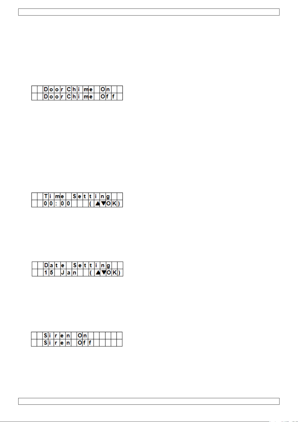
CTC1000
Pour accéder à cette option : activer le mode de programmation, ouvrir l'option "Gen. Settings",
sélectionner "H. Exit Time" et appuyer sur OK.
Remarques
Appuyer sur le bouton "Home" sur la télécommande pour redémarrer le compte à rebours.
Appuyer sur le bouton "Disarm" sur la télécommande pour arrêter le compte à rebours et désarmer le
système.
Composer un code d'accès pour arrêter le compte à rebours et désarmer l'alarme.
7.12 Carillon de porte
L'option "Door Chime" branche ou débranche le carillon de porte lorsqu'un contact de porte/fenêtre ou de
mouvement est déclenché en mode "Disarm".
Conditions préalables :
Etat de l'alarme : débranché
Dispositifs concernés : contact de porte/fenêtre ou détecteur de mouvement définis comme Entrée ou
Entrée Surveillance (voir 9.3).
Action : si un contact de porte/fenêtre ou détecteur de mouvement est déclenché en mode "Disarm", le
panneau émet un son de carillon de porte.
Le réglage par défaut est OFF.
Pour accéder à cette option: activer le mode de programmation, ouvrir l'option "Gen. Settings", sélectionner
"Door Chime" et appuyer sur OK.
7.13 Heure
L'option "Time" permet de régler l'heure.
1. Pour accéder à cette option : activer le mode de programmation, ouvrir l'option "Gen. Settings",
sélectionner "Time" et appuyer sur OK.
2. Utiliser les touches fléchées pour définir l'heure et appuyer sur OK.
3. Utiliser les touches fléchées pour définir les minutes et appuyer sur OK.
7.14 Date
L'option "Time" permet de régler la date.
1. Pour accéder à cette option : activer le mode de programmation, ouvrir l'option "Gen. Settings",
sélectionner "Date" et appuyer sur OK.
2. Utiliser les touches fléchées pour définir le mois et appuyer sur OK.
3. Utiliser les touches fléchées pour définir le jour et appuyer sur OK.
7.15 Sirène du panneau
L'option "Panel Siren" (sirène du panneau) permet de brancher ou de débrancher l'alarme sur le panneau si un
événement se produit.
1. Pour accéder à cette option : activer le mode de programmation, ouvrir l'option "Gen. Settings",
sélectionner "Panel Siren" et appuyer sur OK.
2. Utiliser les touches fléchées pour sélectionner l'option et appuyer sur OK.
V. 01 – 12/06/2013 85 ©Velleman nv
Page 86
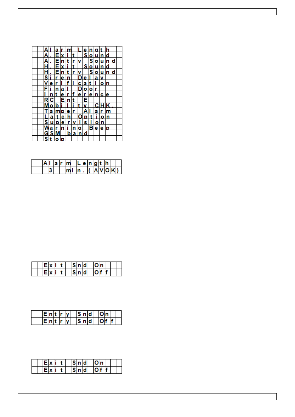
CTC1000
8. Special Settings
Pour accéder aux options du menu "Spc. Settings" :
Activer le mode de programmation et ouvrir l'option "Spc. Settings".
Alarm Length (longueur de l'alarme)
Règle la longueur de la sirène intégrée au panneau quand une alarme est déclenchée.
Les options sont : Disable (aucune alarme) et 1 à 15 minutes.
La valeur par défaut est 3 minutes.
Remarques
Si l'option "Disable" est sélectionnée et que le panneau reçoit un signal d'alarme, ni la sirène du panneau ni
les sirènes internes et externes n'émettront de signal.
Si la durée de l'alarme de la sirène extérieure est supérieure à celle du panneau, la durée du panneau
prévaut. par exemple, si la longueur de l'alarme est réglée à 3 minutes et l'alarme du panneau à 1 minute,
les deux alarmes s'arrêteront au bout d'une minute; cependant, les LEDs de la sirène clignoteront pendant
3 minutes.
A. Exit Sound
(=away exit sound)
Branche ou débranche le signal de sortie du minuteur (away exit timer).
A. Entry Sound
(=away entry sound)
Branche ou débranche le signal d'entrée du minuteur (away entry timer).
H. Exit Sound
(signal de sortie en mode "Home")
V. 01 – 12/06/2013 86 ©Velleman nv
Page 87

CTC1000
Branche ou débranche le signal de sortie du minuteur en mode "Home"
H. Entry Sound
(signal d'entrée en mode "Home")
Branche ou débranche le signal d'entrée du minuteur en mode "Home"
Temporisation de sirène
Détermine si le panneau doit retarder ou ne pas émettre les signaux pour les alarmes d'intrusion et d'entrée.
Les options sont : Off (pas de son) et des délais de 1 à 10 minutes.
Le réglage par défaut est OFF.
Remarques
La temporisation de la sirène s'applique uniquement aux alarmes d'intrusion et d'entrée. Les autres types
d'alarmes ne seront pas retardés :
o Alarme d'incendie
o Alarme de présence d'eau
o Alarme panique
o Urgence médicale
o Alarme sabotage
o Erreur GSM
Même si les signaux auditifs sont retardés, le rapport d'alarme sera envoyé sans délai.
Vérification
Règle l'ordre de vérification pour les alarmes.
Seq. verif. on [vérification séquentielle branchée]
Si la vérification séquentielle est mise sur ON et
Si l'installation comporte plus d'un détecteur (contact de porte/fenêtre ou détecteur PIR ) avec attribut
Intrusion
o Si le premier détecteur est déclenché, le panneau envoie un message signalant l'intrusion.
o Si le deuxième détecteur est déclenché dans les 30 secondes, le panneau envoie un message de
confirmation.
Seq. verif. off [vérification séquentielle débranchée]
Si la vérification séquentielle est OFF, le panneau de contrôle envoie uniquement un message signalant
l'intrusion.
Final Door (dernière porte)
V. 01 – 12/06/2013 87 ©Velleman nv
Page 88

CTC1000
Option
Fonction
Away Arm Only
Le panneau déclenche une alarme locale et envoie un rapport s'il se
trouve en mode "Away".
Si l'alarme se trouve en mode "Home" ou "Alarm Off", le système
Si l'option "Final Door" (dernière porte) se trouve sur ON
Si le système d'alarme est mis en mode "Away Arming" et
Si un contact de porte/fenêtre a été défini comme dispositif d'entrée
Le système activera automatiquement la surveillance dès qu'il a détecté la fermeture du contact de
porte/fenêtre, et ce même si le délai de sortie n'est pas écoulé.
Interférence
Détermine si le panneau doit ou non détecter les interférences causées par des signaux extérieurs.
Si la détection est branchée et que le système détecte une interférence de plus de 30 secondes, l'erreur
sera consignée, signalée au système de rapportage central et affichée.
Si la détection est débranchée, le système ne vérifiera pas les signaux d'interférence.
RC Ent E (= entrée avec télécommande)
Cette option évite que l'alarme ne soit débranchée à l'aide d'une télécommande avant qu'une porte n'ait été
ouverte, par exemple en cas de vol de la télécommande.
Pour accéder à la fonction:
il faut d'abord activer dispositif du point d'entrée pour pouvoir désarmer l'alarme.
Si la télécommande est mise sur ON :
une télécommande peut désarmer l'alarme sans qu'une porte n'ait été ouverte.
Mobility
Cette option branche ou débranche le minuteur "Mobility" et permet de définir le délai. Les options sont Disable,
4 heures, 8 heures et 12 heures.
Si le minuteur "Mobility" est actif, le système comptera la durée définie. Si le minuteur expire sans être remis à
zéro, un rapport sera envoyé aux numéros de téléphone programmés.
Si le minuteur "Mobility" est réglé avec délai spécifié, le panneau fera rapport aux numéros de téléphone
programmés lorsque le délai expire, à moins que l'une des actions suivantes ne se produise avant la remise
à zéro du minuteur :
o En mode "Home" : chaque fois qu'un détecteur Home Omit DC, ou de mouvement est déclenché, ou à
chaque fois appui sur une des touches du panneau;
o En mode "Disarm" : chaque fois qu'un contact de porte/fenêtre ou détecteur de mouvement est
déclenché (sauf 24 h, incendie, urgence médicale et détection d'eau), ou chaque fois que l'une des
touches du panneau de commande est pressée.
Si le système se trouve en mode "Away Arm", le minuteur s'arrête automatiquement. Si le système est mis
en mode "Home Arm" ou "Disarm", le minuteur se remet en marche.
Alarme anti-sabotage
Permet de définir si la sirène retentira en cas de tentative de sabotage.
V. 01 – 12/06/2013 88 ©Velleman nv
Page 89

CTC1000
enverra un rapport mais la sirène ne retentira pas.
Normal
Le panneau déclenche une alarme locale et envoie un rapport dans
tous les modes.
Remarques
Indépendamment du réglage de la sirène, le panneau enverra un
rapport de sabotage par SMS au premier numéro de téléphone de la
liste, et ce dans tous les modes.
Dès que la situation de sabotage est rétablie, le panneau adressera un
SMS au premier numéro de téléphone.
Remarques
Si la fonction de rapportage Latch est mise sur OFF, l'option ne sera
pas visible dans le menu de maintenance (voir 7.5).
Si la fonction de rapportage Latch est mise sur ON, toute action
d'armement ou de désarmement sur le panneau et les commandes à
distances seront rapportées au système de suivi central.
Pour pouvoir recevoir des rapports par SMS, définir le premier numéro
comme rapport SMS.
Option "Latch" [suivi des actions d'armement et de désarmement]
L'option "Latch" enregistre toutes les actions d'armement et de désarmement effectués par tous les utilisateurs
depuis le panneau et les commandes à distance.
Supervision
L'option "Supervision" permet une supervision du système. Si l'option est mise sur ON, le panneau de contrôle
peut recevoir des signaux d'identification émis par les dispositifs et indiquant leur bon fonctionnement.
Les options sont : Disable, 8 heures, 12 heures, et 24 heures.
Signal d'avertissement
Active ou désactive le signal sonore lorsque le panneau affiche un message d'erreur
La lecture du message d'erreur débranche le signal.
Bande GSM
Modifier l'option "GSM band" (réseau GSM) en fonction des paramètres de bande passante du fournisseur
d'accès. Consulter votre fournisseur pour le réglage correct.
Stop
Sélectionner "Stop" et appuyer sur OK pour valider et retourner au menu précédent.
V. 01 – 12/06/2013 89 ©Velleman nv
Page 90

CTC1000
9. Gestion des dispositifs
Le menu "Devices+/-" permet la gestion des dispositifs (ajout, configuration, modification, suppression) tels
que contacts de porte/fenêtre et détecteurs de mouvement, sirènes, dans 30 zones maximum.
Ordre d'installation
Le système considère les sirènes intérieures et extérieures ainsi que les récepteurs universels comme des
dispositifs auxiliaires. Avant d'ajouter un dispositif auxiliaire, ajouter au moins un autre type de dispositif (par
exemple un contact de porte/fenêtre ou détecteur de mouvement ou une télécommande).
9.2 Ajouter un dispositif
Pour accéder à la fonction :
1. Activer le mode de programmation, accéder à l'option "Devices+/-", sélectionner "Add device" et appuyer
sur OK.
2. Appuyer le bouton de test sur le dispositif à ajouter.
3. Si le panneau détecte un dispositif, il affiche le type :
Les dispositifs possibles sont :
Door Contact [contact de porte/fenêtre]
PIR Sensor [détecteur de mouvement]
External PIR Sensor [détecteur de mouvement extérieur]
La télécommande
Remote Keypad [clavier de commande]
Sonde de niveau d'eau
Outdoor Siren [sirène extérieure]
Récepteur universel
4. Appuyer sur OK pour valider.
Le panneau affiche alors les zones de défense inutilisées (30 zones maximum).
5. Utiliser les touches fléchées pour sélectionner le numéro de zone auquel vous voulez associer le dispositif et
appuyer sur OK.
La procédure varie en fonction du dispositif à ajouter.
6. Sélectionner "Stop" et appuyer sur OK pour valider et retourner au menu précédent.
V. 01 – 12/06/2013 90 ©Velleman nv
Page 91

CTC1000
Remarques
En essayant d'ajouter un détecteur qui est déjà présent, un message d'erreur apparaît.
Pour l'ajouter quand même, il vous faudra d'abord le supprimer (voir 9.5 Supprimer un dispositif).
Appuyer sur le bouton pour annuler la procédure.
Les affichages qui suivent varient en fonction du dispositif à ajouter.
Ajouter un contact de porte/fenêtre
1. Utiliser les touches fléchées pour sélectionner un mode de fonctionnement et appuyer sur OK.
Pour plus de détails sur les modes de fonctionnement disponibles, voir 9.3.
2. Entrer un nom pour la zone.
Ne taper aucune donnée si vous ne souhaitez pas utiliser de nom.
3. Appuyer à nouveau sur OK pour valider l'installation.
4. Appuyer à nouveau sur OK pour terminer.
Ajouter un détecteur de mouvement
En supposant que vous avez associé un numéro de zone (voir 9.2):
1. Utiliser les touches fléchées pour sélectionner un mode de fonctionnement et appuyer sur OK.
Pour plus de détails sur les modes de fonctionnement disponibles, voir 9.3.
2. Entrer un nom pour la zone.
Ne taper aucune donnée si vous ne souhaitez pas utiliser de nom.
V. 01 – 12/06/2013 91 ©Velleman nv
Page 92
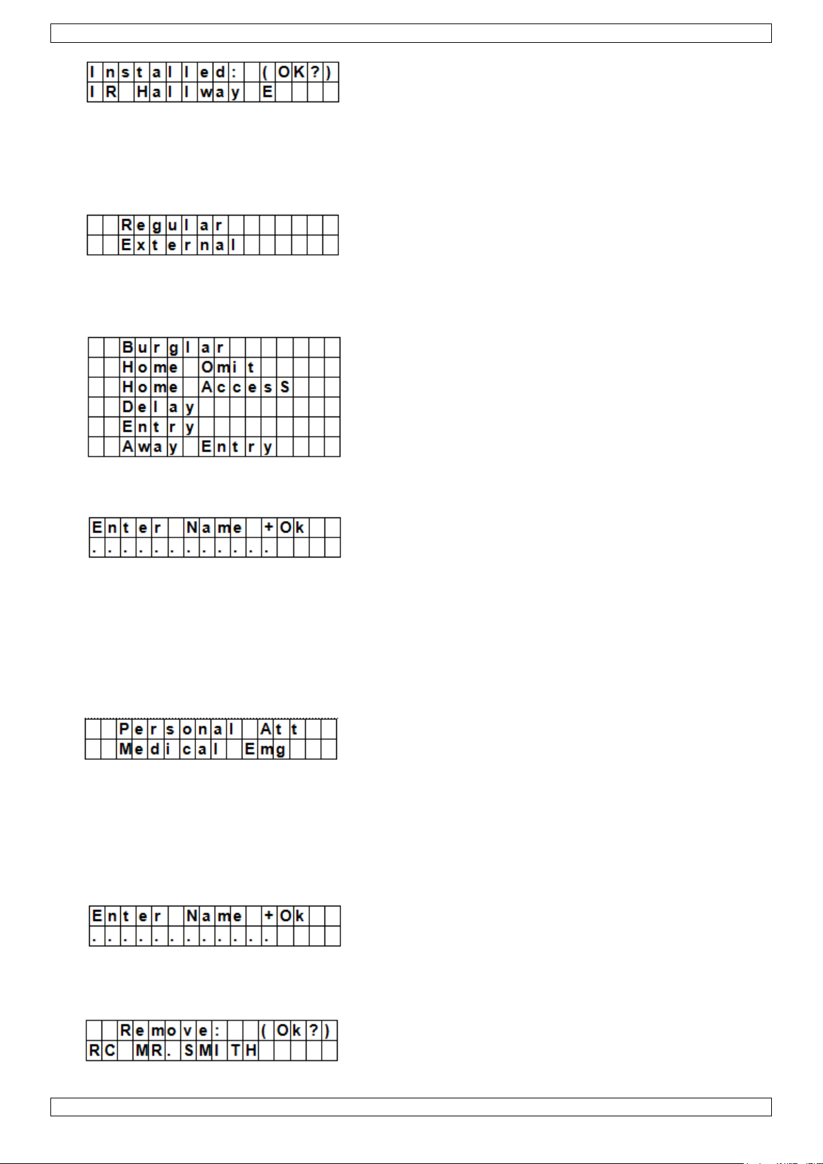
CTC1000
3. Appuyer à nouveau sur OK pour valider l'installation.
4. Appuyer à nouveau sur OK pour terminer.
Ajouter un détecteur de mouvement externe
En supposant que vous avez associé un numéro de zone (voir 9.2):
1. Utiliser les touches fléchées pour sélectionner un type de détecteur et appuyer sur OK.
o Regular : le dispositif sera ajouté comme détecteur normal
o External : le dispositif sera ajouté comme détecteur extérieur.
2. Utiliser les touches fléchées pour sélectionner un mode de fonctionnement et appuyer sur OK.
Pour plus de détails sur les modes de fonctionnement disponibles, voir 9.3.
3. Entrer un nom pour la zone.
Ne taper aucune donnée si vous ne souhaitez pas utiliser de nom.
Pour plus de détails sur la saisie de texte, voir 17.
4. Appuyer à nouveau sur OK pour valider l'installation.
5. Appuyer à nouveau sur OK pour terminer.
Ajouter une télécommande
En supposant que vous avez associé un numéro de zone (voir 9.2):
1. Utiliser les touches fléchées pour sélectionner l'option souhaitée pour la télécommande.
o Personal att : le panneau émet une alarme urgence médicale si quelqu'un appuie sur le bouton de
détresse pendant 3 secondes ou appuie sur le bouton 2 fois dans les 3 secondes.
o Medical Emg : le panneau émet une alarme urgence médicale si quelqu'un appuie sur le bouton de
détresse pendant 3 secondes ou appuie sur le bouton 2 fois dans les 3 secondes.
2. Utiliser les touches fléchées pour sélectionner un mode de fonctionnement et appuyer sur OK.
Pour plus de détails sur les modes de fonctionnement disponibles, voir 9.3.
3. Entrer un nom pour la zone.
Ne taper aucune donnée si vous ne souhaitez pas utiliser de nom.
Pour plus de détails sur la saisie de texte, voir 17.
4. Appuyer à nouveau sur OK pour valider l'installation.
V. 01 – 12/06/2013 92 ©Velleman nv
Page 93

CTC1000
Mode de
fonctionnement
Etat du système
Comportement du dispositif
Burglar
(Intrusion)
Si le système se trouve en mode "Away
Arm/Home Arm" ou pendant les délais
d'entrée et de sortie
si un contact de porte/fenêtre d'intrusion est
déclenché, le système activera immédiatement
une alarme intrusion
Home Omit
(Ignorer
Maison)
le système d'alarme est en mode "Away
Arm" (y compris "Away Arm Entry)"
si un détecteur de mouvement home omit est
déclenché, le système active immédiatement
une alarme intrusion
si un détecteur de mouvement home omit
et déclenché alors que le système se
trouve en mode "Home Arm".
le panneau ne réagit pas
pendant le délai d'entrée ou de sortie, si
un contact de mouvement Home Omit
(Ignorer Maison) est déclenché
le panneau ne réagit pas
Home Access
le système d'alarme est en mode "Away
Arm"
si un détecteur de mouvement Accès Maison
est déclenché, le système émet
immédiatement une alarme intrusion
le système d'alarme est en mode "Home
Arm"
si un détecteur de mouvement Accès Maison
est déclenché, le panneau initie une période
d‟entrée qui laisse assez de temps pour
désarmer le système
pendant le délai d'entrée ou de sortie
si un détecteur de mouvement Accès Maison
est déclenché, le panneau ne réagit pas
Délai
le système d'alarme est en mode "Away
Arm/Home Arm"
si un contact de porte/fenêtre délai est
déclenché, le système activera immédiatement
une alarme intrusion
pendant le délai d'entrée ou de sortie
si un détecteur de mouvement zone de délai
est déclenché, le panneau ne réagit pas
Entrée
le système d'alarme est en mode "Away
Arm/Home Arm"
si un détecteur de mouvement Entrée est
déclenché, le panneau initie une période
d‟entrée qui laisse assez de temps pour
désarmer le système
après expiration de la période de délai et
qu'aucun code d'accès n'a été donné pour
désarmer le système
le panneau émet une alarme intrusion après 30
secondes
5. Appuyer à nouveau sur OK pour terminer.
Ajouter un clavier de commande ou une sonde de niveau d'eau
Ces dispositifs s'installent de façon similaire.
En supposant que vous avez associé un numéro de zone (voir 9.2):
1. Entrer un nom pour la zone.
Ne taper aucune donnée si vous ne souhaitez pas utiliser de nom.
Pour plus de détails sur la saisie de texte, voir 17.
2. Appuyer sur OK.
3. Appuyer à nouveau sur OK pour terminer.
Ajouter un dispositif auxiliaire (menu Program Siren)
Le système considère les sirènes intérieures et extérieures ainsi que les récepteurs universels comme des
dispositifs auxiliaires. Avant d'ajouter un dispositif auxiliaire, ajouter au moins un autre dispositif (détecteur ou
clavier de commande). Le système affiche une erreur si ce n'est pas le cas.
1. Activer le mode de programmation, accéder à l'option "Devices+/-", sélectionner "Program Siren", puis
"Learn Siren" et appuyer sur OK.
2. Mettre le dispositif à ajouter en mode d'apprentissage (voir le manuel du dispositif).
3. Appuyer sur OK.
Le panneau émet un long bip et transmet le code d'apprentissage à tous les dispositifs à la fois. La sirène
extérieure produira un son et clignotera. La LED sur le récepteur universel clignote 3 fois.
9.3 Ajouter un dispositif : aperçu des modes de fonctionnement
L'aperçu ci-dessous contient tous les modes possibles pour tous les dispositifs. Le type de dispositif détermine
quels sont les modes qui sont d'application.
V. 01 – 12/06/2013 93 ©Velleman nv
Page 94
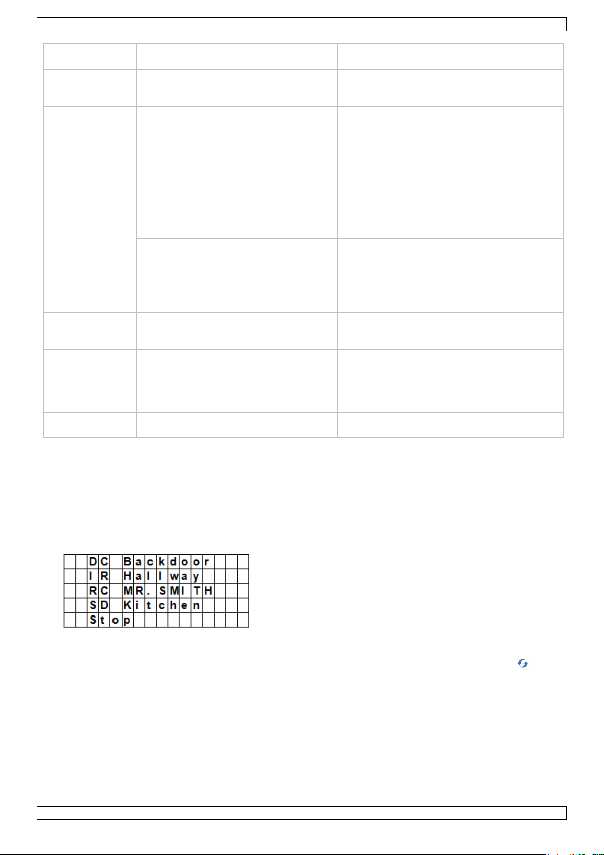
CTC1000
Mode de
fonctionnement
Etat du système
Comportement du dispositif
le système d'alarme est désarmé
si un détecteur de mouvement Entrée est
déclenché, le panneau émet un son de carillon
(si le panneau est programmé comme tel).
Away Entry
le système d'alarme est en mode "Away
Arm"
si un détecteur de mouvement Entrée
Surveillance est déclenché, le panneau initie
une période d‟entrée qui laisse assez de temps
pour désarmer le système
après expiration de la période de délai et
qu'aucun code d'accès n'a été donné pour
désarmer le système
le panneau met une alarme intrusion après 30
secondes
le système d'alarme est désarmé
si un détecteur de mouvement Entrée
Surveillance est déclenché, le panneau émet
un son de carillon (si le panneau est
programmé comme tel).
le système d'alarme est en mode "Home
Arm"
si un détecteur de mouvement Entrée
Surveillance est déclenché, le panneau ne
réagit pas
pendant le délai d'entrée ou de sortie
si un détecteur de mouvement Entrée
Surveillance est déclenché, le panneau ne
réagit pas
24 Hour (24
Heures)
pas applicable
le contact de porte/fenêtre est actif en
permanence et ne doit pas être armé ni
désarmé
Fire (Incendie)
pas applicable
le détecteur d'incendie est actif en permanence
et ne doit pas être armé ni désarmé
Medical Emg
(Urgence
médicale)
pas applicable
une alarme d'urgence médicale est active en
permanence et ne doit pas être armée ou
désarmée
Water (Eau)
pas applicable
le détecteur d'eau est actif en permanence et
ne doit pas être armé ni désarmé
9.4 Modifier un dispositif
La fonction varie en fonction du type de dispositif.
Modifier un contact de porte/fenêtre - détecteur de mouvement - télécommande
Activer le mode de programmation, accéder à l'option "Devices+/-", sélectionner "Edit devices" et appuyer
sur OK.
L'écran affiche les dispositifs disponibles.
1. Utiliser les touches fléchées pour sélectionner un dispositif et appuyer sur OK.
Maintenant, il est possible de changer l'attribut du dispositif. Pour passer cette étape, appuyer sur .
V. 01 – 12/06/2013 94 ©Velleman nv
Page 95

CTC1000
2. Utiliser les touches fléchées pour sélectionner un attribut et appuyer sur OK.
3. Appuyer sur OK pour valider.
Maintenant, il est possible de changer ne nom du dispositif. Pour passer cette étape, appuyer sur .
Appuyer sur OK pour continuer.
4. Taper un nom de zone et appuyer sur OK.
L'écran retourne à la liste des dispositifs. Utiliser les touches fléchées pour sélectionner un autre dispositif
ou appuyer sur .
Modifier un clavier de commande - une sonde de niveau d'eau
1. Activer le mode de programmation, accéder à l'option "Devices+/-", sélectionner "Edit devices" et appuyer
sur OK.
L'écran affiche les dispositifs disponibles.
2. Maintenant, il est possible de changer le nom du dispositif.
3. Taper un nom de zone et appuyer sur OK.
L'écran retourne à la liste des dispositifs. Utiliser les touches fléchées pour sélectionner un autre dispositif
ou appuyer sur .
9.5 Supprimer un dispositif
1. Activer le mode de programmation, accéder à l'option "Devices+/-", sélectionner "Remove device" et
appuyer sur OK.
Le panneau affiche tous les dispositifs disponibles.
V. 01 – 12/06/2013 95 ©Velleman nv
Page 96

CTC1000
2. Utiliser les touches fléchées pour sélectionner un dispositif et appuyer sur OK.
Pour plus de détails sur les modes de fonctionnement disponibles, voir 9.3.
3. Appuyer à nouveau sur OK pour valider.
9.6 Menu Program Siren - autres options
Learn Siren (apprentissage d'une sirène)
Pour ajouter une sirène interne ou externe, le dispositif doit d'abord être programmé par le panneau, pour
permettre la communication entre le panneau et les dispositifs auxiliaires.
Avant d'ajouter un dispositif auxiliaire, ajouter au moins un autre type de dispositif (par exemple un contact de
porte/fenêtre ou détecteur de mouvement, mais pas de sirène interne ou externe).
Avant d'ajouter un dispositif auxiliaire, ajouter au moins un autre type de dispositif (par exemple un contact de
porte/fenêtre ou détecteur de mouvement ou une télécommande).
Pour ajouter une sirène externe ou interne
1. Mettre le ou les dispositifs concernés en mode d'apprentissage.
2. Activer le mode de programmation, accéder à l'option "Devices+/-", sélectionner "Program Siren" et
appuyer sur OK.
3. Utiliser les touches fléchées pour sélectionner "Learn Siren" et appuyer sur OK.
o Le panneau émet un long bip et transmet le code d'apprentissage à tous les dispositifs à la fois.
o La sirène extérieure produira un son et clignotera.
4. Arrêter le mode d'apprentissage sur les dispositifs auxiliaires. Les dispositifs ont été ajoutés au système.
Siren Tamp. On - Siren Tamp. Off (anti-sabotage sirène)
L'anti-sabotage de la sirène peut être activé et désactivé à distance.
Cette fonction est utile quand on remplace les piles.
Pour désactiver l'anti-sabotage de la sirène : sélectionner "Siren Tamp.Off" et appuyer sur OK.
La protection anti-sabotage sera simultanément désactivée sur toutes les sirènes.
Pour activer l'anti-sabotage de la sirène : sélectionner "Siren Tamp.Off" et appuyer sur OK.
La protection anti-sabotage sera simultanément réactivée sur toutes les sirènes.
Confirm On - Confirm Off
Avec l'option ON, la sirène émettra un bip de confirmation lors de l'armement ou du désarmement du
système.
Avec l'option OFF, la sirène n'émettra pas de bip de confirmation lors de l'armement ou du désarmement du
système.
Sélectionner l'option "Confirm On" ou "Confirm Off" et appuyer sur OK.
Entry Snd On - Entry Snd Off
Active ou désactive les bips de délai d'entrée en entrant dans votre habitation.
Sélectionner l'option "Entry Snd On" ou "Entry Snd Off" appuyer sur OK.
V. 01 – 12/06/2013 96 ©Velleman nv
Page 97

CTC1000
10. Autres fonctions de configuration
SMS Editor [éditeur SMS]
Cette fonction permet de définir le message qui sera envoyé au téléphone portable en cas d'alarme.
1. Activer le mode de programmation et sélectionner "SMS Editor "dans le menu.
L'écran d'édition apparaît.
2. Composer un message SMS (jusqu'à 16 x 4 caractères).
Pour plus de détails sur la saisie de texte, voir 17.
3. Appuyer sur OK.
4. Sélectionner "Save" et appuyer sur OK pour valider.
SMS Keyword [mot-clé SMS]
Le panneau fonctionne avec des commandes envoyées depuis un téléphone portable. Avant de pouvoir envoyer
une commande DTMF, fournir d'abord un mot-clé (SMS keyword). Le mot-clé est identique ou code d'accès par
défaut (voir 7.4 Pin code).
Pour modifier le code d'accès pour les messages à distance
1. Activer le mode de programmation, sélectionner l'option "SMS Keyword" du menu et appuyer sur OK.
2. Composer un code de 4 chiffres et appuyer sur OK.
3. Répéter le code et appuyer sur OK.
Country Code [code pays]
Le format d'affichage du numéro de téléphone (avec ou sans préfixe national) peut varier en fonction du
fournisseur de téléphonie mobile.
Si votre téléphone affiche les numéros sans code pays, vous pouvez ignorer ce point.
Si votre téléphone affiche les numéros avec code pays, il vous faudra modifier un paramètre dans le panneau.
Demander cette donnée à votre fournisseur ou effectuer le test suivant :
1. Insérer la carte concernée dans un téléphone mobile.
2. Brancher le téléphone.
3. S'assurer que le numéro ne soit associé à aucun contact sur votre téléphone.
4. Envoyer un SMS au même numéro.
o Si votre téléphone affiche les numéros sans code pays (par exemple 01234567890), ignorer ce point.
o Si votre téléphone affiche les numéros avec code pays (par exemple +321234567890), procéder
comme suit.
5. Sur le panneau de contrôle, activer le mode de programmation, sélectionner l'option "Country Code" et
appuyer sur OK.
6. Composer le code de votre pays.
Exemple : si le numéro affiché était le +321234567890, taper 32 (sans le '+').
V. 01 – 12/06/2013 97 ©Velleman nv
Page 98

CTC1000
7. Appuyer sur OK.
8. Dans l'écran suivant, taper 0.
9. Appuyer sur OK pour terminer.
GSM Signal (signal GSM)
L'option "GSM signal" permet de vérifier la puissance du signal GSM.
1. Sur le panneau de contrôle, activer le mode de programmation, sélectionner l'option "GSM signal" et
appuyer sur OK.
L'écran affiche la puissance du signal (de 0 à 9, 9 indiquant le signal le plus puissant).
Walk Test [test de communication]
L'option "Walk Test" permet de vérifier la communication entre le panneau et un dispositif.
1. Sur le panneau de contrôle, activer le mode de programmation, sélectionner l'option" Walk Test" et appuyer
sur OK.
2. Appuyer le bouton de test sur le dispositif à tester.
Si le panneau de contrôle reçoit un signal, il affichera le nom, la zone et la force du signal.
3. Appuyer sur pour quitter.
Reset GSM [Initialisation GSM]
L'option "Reset GSM" initialise le signal GSM.
1. Sur le panneau de contrôle, activer le mode de programmation, accéder à "Reset GSM" et appuyer sur OK.
L'initialisation du signal prend environ 1 minute.
11. Utiliser le système d'alarme
En supposant que l'alarme est désarmée : taper votre code d'accès pour accéder au menu utilisateur. Depuis ce
menu, il est possible d'armer ou de désarmer l'alarme.
Taper le premier chiffre de votre code d'accès.
1. Dans les 10 secondes, composer les autres chiffres du code. L'écran affiche :
2. Le curseur clignote à côté de l'option "Away Arm". Le menu contient les éléments suivants :
V. 01 – 12/06/2013 98 ©Velleman nv
Page 99

CTC1000
Si le système détecte une erreur, la première ligne de l'écran affiche :
11.2 Brancher l'alarme
Si le système est désarmé, il est possible de l'armer comme suit :
1. Taper votre code d'accès et appuyer sur OK. L'écran affiche :
2. Le curseur clignote à côté de l'option "Away Arm". Appuyer sur OK. L'écran affiche :
o Le panneau lance le compte à rebours et émet un son.
(Le son et le délai de sortie dépendent de votre configuration, voir 7.9.)
o Une fois le délai de sortie écoulé, le système émet un long son et passe en mode "Arm".
Remarques
Le panneau de contrôle à une fonction d'économiseur d'écran. Le message "Alarm ON" s'affiche pendant
180 secondes. Ensuite, l'écran affiche la date et l'heure.
Si l'option "Final Door" est à ON, le panneau armera le système dès que la porte a été fermée.
Il n'est pas possible d'armer le système si un contact de porte/fenêtre ou détecteur de mouvement a été
déclenché (par exemple : une porte restée ouverte). Pour quand même armer le système, voir "Armement
forcé" ci-dessous.
Le système peut aussi être armé à l'aide de la télécommande (en option).
Arrêter le délai de sortie
Après avoir armé le système et le compte à rebours est toujours en cours, le délai de sortie peut être arrêté en
désarmant le système.
1. Appuyer sur la touche .
Le système demande d'entrer votre code d'accès.
L'écran affiche le compte à rebours.
2. Taper votre code d'accès et appuyer sur OK.
"Alarm Off" sera affiché sur l'écran et le système revient en mode "Disarm".
o Le délai de sortie peut également être arrêté en appuyant sur le bouton de désarmement de la
télécommande (en option).
o Si le délai de sortie expire avant qu'un code n'ait été donné, le système sera armé.
Prolonger le délai de sortie (télécommande uniquement)
Pendant le délai de sortie, il est possible de prolonger ce délai ou appuyant sur le bouton Armer de la
télécommande (en option)
Enfoncer le bouton d'armement pendant 1 seconde. Le panneau émet un long bip confirmant le
prolongement.
Le temps de délai est remis à zéro à chaque appui sur le bouton d'armement.
V. 01 – 12/06/2013 99 ©Velleman nv
Page 100

CTC1000
11.3 Armement forcé du système
En introduisant votre code d'accès alors que le système a détecté une erreur, l'écran affiche une erreur.
Si dans ce cas, choisir l'option "Away Arm", le panneau émettra un avertissement indiquant que l'armement est
impossible. L'écran affiche alternativement le message "Fault Dsp". suivi du message d'erreur concerné.
Appuyer sur la touche pour retourner à l'écran "Alarm Off".
En cas d'erreur,
solutionner les problèmes et effacer les messages d'erreur (voir 14 et armer le système (recommandé).
ignorer les erreurs et quand-même armer le système, comme suit :
Dans l'écran "Fault Dsp" :
1. Taper votre code d'accès et appuyer sur OK. L'écran affiche :
2. Appuyer sur OK pour valider.
o Le panneau lance le compte à rebours et met un son.
(Le son et le délai de sortie dépendent de votre configuration, voir 7.9.)
o Une fois le délai de sortie écoulé, le système émet un long son et passe en mode "Arm".
Armement avec porte ouverte
Si le système détecte l'ouverture d'une porte pendant l'armement, le panneau émettra un son indiquant
que l'armement est impossible. L'écran affiche le texte "Fault DSP" alternant avec le nom du détecteur
concerné.
Après avoir fermée la porte ouverte, les messages d'erreurs seront effacés et l'écran retourne en mode
"Alarm Off". Maintenant, il est possible d'armer le système.
Pour quand même armer le système si une porte est ouverte, utiliser "Forced Arming".
Remarques
L'écran "Fault Dsp" disparaît après 5 minutes. Après cela, il retourne à l'écran "Alarm Off".
Si un détecteur est contourné (voir "Partial Arm"), l'état de ce détecteur ne sera pas contrôlé.
En cas de sabotage ou de panne d'un détecteur, il est possible de le contourner temporairement ou le
supprimer définitivement.
11.4 Désarmer le système
Il est possible de désarmer le système si celui-ci se trouve soit en mode "Away Arm" soit en "Home Arm"
(Alarm ON) :
1. Taper votre code d'accès et appuyer sur OK. Le panneau émet 2 bips et retourne en mode "Disarm".
Commande à distance
Si l'alarme est en mode "Home", il est possible de la désarmer en appuyant sur le bouton de désactivation
de la télécommande.
Si l'alarme est en "Away Arm", appuyer sur le bouton de désactivation pour soit désarmer le système (si un
dispositif d'entrée a été déclenché) ou si la fonction RC Ent E (= entrée avec télécommande) se trouve sur
ON (voir RC Ent E) du chapitre 8).
V. 01 – 12/06/2013 100 ©Velleman nv
 Loading...