

Velleman CCTVPROMT1 Quick Installation Manual
CCTVPROMT1
HD CCTV VIDEO SECURITY SYSTEM - 4-CHANNELS - 2 IR CAMERAS - PUSH
VIDEO/STATUS + IVS
HD-BEWAKINGSSYSTEEM - 4 K ANALEN - 2 IR-CAMERA'S - PUSH
VIDEO/STATUS + IVS
SYSTÈME DE VIDÉOSURVEILLANCE HD - 4 CANAUX - 2 CAMÉRA'S IR PUSH VIDEO/STATUS + IVS
SISTEMA DE VIDEOVIGILANCIA DE ALTA DEFINICIÓN - 4 CANALES - 2
CÁMARAS IR - PUSH VÍDEO/STATUS + IVS
HD VIDEO-ÜBERWACHUNGSSYSTEM - 4 KANÄLE - 2 IR-KAMERAS - PUSH
VIDEO/STATUS + IVS
SYSTEM BEZP IECZEŃSTWA VIDEO WYSOKIEJ ROZDZIELCZOŚCI -
4 KANAŁY - 2 KAMERY IR - FUNKCJA PUSH VIDEO/STATUS + IVS
SISTEM DE VÍDEO-VIGILÂNCIA COM ALTA DEFINIÇÃO - 4 CANAIS - 2
CÂMARAS IR - PUSH VIDEO/STATUS + IVS
QUICK INSTALLATION GUIDE 3
KORTE HANDLEIDING 24
GUIDE D'INSTALLATION RAPIDE 45
GUÍA RÁPIDA 67
SCHNELLEINSTIEG 89
SKRÓCONA INSTRUKCJA INSTALACJI 111
GUIA RÁPIDO PARA INSTALAÇÃO 133

CCTVPROMT1
V. 01 – 25/02/2016 2 ©Velleman nv
2 x
EN 1 12 VDC input terminal
2
Video output connector
NL 1 12VDC-ingangsaansluiting
2
Video-uitgangsaansluiting
FR 1 Connexion d’entrée 12 VCC
2
Connexion de sortie vidéo
ES 1 Conexión de entrada 12 VCC
2
Conexión de salida de vídeo
DE 1 12VDC-Eingangsanschluss
2
Video-Ausgangsanschluss
PL 1 Wejście zasilania 12 VDC
2
Złącze wyjściowe wideo
PT 1 Terminal de entrada 12 VDC
2
Conector de saída de vídeo
EN
Actual product may differ from the shown images due to product enhancement.
NL
Door productverbetering kan het product afwijken van de getoonde afbeeldingen.
FR
Les images peuvent différer du produit réel en raison des améliorations constantes effectuées sur le
produit.
ES
Debido a algunas mejoras, el producto actual puede diferir de las imágenes visualizadas.
DE
Durch einige Verbesserungen kann das aktuelle Produkt von dem angezeigten Bild abweichen.
PL
Rzeczywisty produkt może różnić się od przedstawionych rysunków ze względu na wprowadzane
ulepszenia.
PT
O produto atual pode ser diferente das imagens apresentadas devido ao aperfeiçoamento do mesmo.
CCTVPROMT1
V. 01 – 25/02/2016 3 ©Velleman nv
QUICK INSTALLATION GUIDE
1. Introduction
To all residents of the European Union
Important environmental information about this product
This symbol on the device or the package indicates that disposal of the device after its lifecycle could
harm the environment. Do not dispose of the unit (or batteries) as unsorted municipal waste; it should
be taken to a specialized company for recycling. This device should be returned to your distributor or
to a local recycling service. Respect the local environmental rules.
If in doubt, contact your local waste disposal authorities.
Thank you for choosing Velleman! Please read the manual thoroughly before bringing this device into service. If
the device was damaged in transit, do not install or use it and contact your dealer.
NOTE: This document is a Quick installation guide. For more details, refer to the full user manual, which can
be found on the included CD-ROM. Download the multilingual version of this document from www.velleman.eu.
This high-definition do-it-yourself security set is a great solution for home or business surveillance.
It contains two full HD CCTV or TVI (High-Definition Transport Video Interface) cameras with infrared LEDs,
20 m of power/signal cable for each camera and a full HD 4-channel digital video recorder which can
record in 1080P format. This system can be extended with other HD CCTV cameras, AHD cameras or 960H
analogue video cameras.
The system features intelligent motion-triggered recording, back-up on a 1 TB hard disk (incl.), via network or
via USB through a multi-language user interface.
Built-in VGA & HDMI interface, 1 audio input and 1 audio output and external alarm inputs.
USB mouse control with graphic user interface and on-screen display. IVS surveillance function including
counting people, virtual fence and single-channel motion recording.
Advanced mobile surveillance via free EagleEyes mobile phone software with push status and push video
function.
The DVR also sends push messages when there is a problem with the system.
The DVR instantaneously sends the video images to the activated mobile device when the alarm is triggered.
2. Safety Instructions
CAUTION
RISK OF ELECTRIC SHOCK
CAUTION:
To reduce the risk of electric shock, do not expose this apparatus to rain or moisture. Only operate this
apparatus from the type of power source indicated on the label. The company shall not be liable for any
damages arising out of any improper use, even if we have been advised of the possibility of such damages.
The lightning flash with arrowhead symbol, within an equilateral triangle, is intended to alert the
user to the presence of non-insulated “dangerous voltages” within the product’s enclosure that may
be of sufficient magnitude to constitute a risk of electric shock to persons.
This exclamation mark within an equilateral triangle is intended to alert the user to the presence of
important operating and maintenance (servicing) instructions in the literature accompanying the
appliance.
Keep the device away from children and unauthorised users.
Risk of electroshock when opening the cover. Touching live wires can cause life-threatening
electroshocks. Have the device repaired by qualified personnel.
Always disconnect mains power when device not in use or when servicing or maintenance activities
are performed. Handle the power cord by the plug only.
DO NOT disassemble or open the cover unless otherwise indicated in this manual. There are no
user-serviceable parts inside the device. Refer to an authorized dealer for service and/or spare
parts.
This is a Safety Class 1 Product (provided with a protective earthing ground incorporated in the
power cord). The mains plug shall only be inserted in a socket outlet provided with a protective
earth contact. Any interruption of the protective conductor inside or outside of the instrument is
likely to make the instrument dangerous. Intentional interruption is prohibited.

CCTVPROMT1
V. 01 – 25/02/2016 4 ©Velleman nv
3. General Guidelines
Refer to the Velleman® Service and Quality Warranty on the last pages of the full user manual which can
be found on the included CD-ROM.
Indoor use only. Keep this device away from rain, moisture, splashing and dripping liquids.
Never put objects filled with liquids on top of or close to the device.
Keep this device away from dust and extreme temperatures. Make sure the ventilation
openings are clear at all times. For sufficient air circulation, leave at least 1" (± 2.5 cm) in front
of the openings.
Protect this device from shocks and abuse. Avoid brute force when operating the device.
Familiarise yourself with the functions of the device before actually using it.
All modifications of the device are forbidden for safety reasons. Damage caused by user modifications to
the device is not covered by the warranty.
Only use the device for its intended purpose. Using the device in an unauthorised way will void the
warranty.
Damage caused by disregard of certain guidelines in this manual is not covered by the warranty and the
dealer will not accept responsibility for any ensuing defects or problems.
Keep this manual for future reference.
DO NOT use this product to violate privacy laws or perform other illegal activities.
4. Features
compression format: H.264 real-time
tribrid video input: AHD, TVI & 960H video
powerful mobile surveillance support on all major platforms including iPad®, iPhone®, BlackBerry®, Windows
Mobile®, Symbian® and Android®
mobile phone connection via 3G/4G data or Wi-Fi
GUI (Graphical User Interface) display and USB mouse control
Intelligent Video Analysis: 4 channels
o virtual fence: a virtual intruder detection line is set to detect intruders crossing the detection line
o flow counting: a virtual detection line is set to detect the moving direction of pedestrians for flow
counting
automatic integrated Dynamic Domain Name Service (DDNS): free service
contains:
o 1 x full HD DVR with push video & status function
o 2 x IR colour cameras: CAMTVI1
o 2 x 20 m camera cables:
o 1 x 19 V PSU
o 1 x high-efficiency DC-DC converter for DVR and cameras: DVR4/DC
multi-language OSD: English, French, Dutch, German, Portuguese, Spanish, Czech, Hungarian, Greek,
Chinese, and Vietnamese
user manual: English
quick start manual: English, Dutch, French, Spanish, German
* computer mouse not included
Note: this product requires a minimum of network installation knowledge

CCTVPROMT1
V. 01 – 25/02/2016 5 ©Velleman nv
5. Hardware Setup
Refer to the illustrations on page 3 of this manual.
Connecting a Video Monitor
Obtain a suitable monitor (not included) and connect it to the HDMI or VGA video output port on the back of
the DVR.
Connecting the Power Supply
1. Plug the DC output connector of the included power adaptor into the 19 VDC power input at the back of
the DVR.
WARNING: only use the included adaptor.
2. Plug the included power cable into the adaptor input connector and plug the other end into the mains.
Do not switch the DVR on yet.
Connecting a Camera
1. You can connect up to four suitable cameras (2 cameras included). Each camera needs its own power
supply.
2. Connect the video output of the camera to either video input at the back of the DVR. The number next to
the input connectors represents the channel number. Connector type is BNC (cables included).
Connecting Audio
1. The DVR supports four audio inputs. Connect the audio output of an audio source to an audio input of the
DVR. Make sure to connect the audio channel to the corresponding video channel. Connector type is BNC.
2. There is also an audio output connector. Connect an audio device, e.g. a speaker to this connector when
desired. Connector type is BNC.
Connecting Local Area Network (LAN)
Connect the DVR to a local network by plugging a network cable into the LAN port at the back of the DVR.
Connector type is 8P8C (RJ45). To setup the network connection, press the Menu button and select . Refer to
the full manual on the included CD-ROM for details.
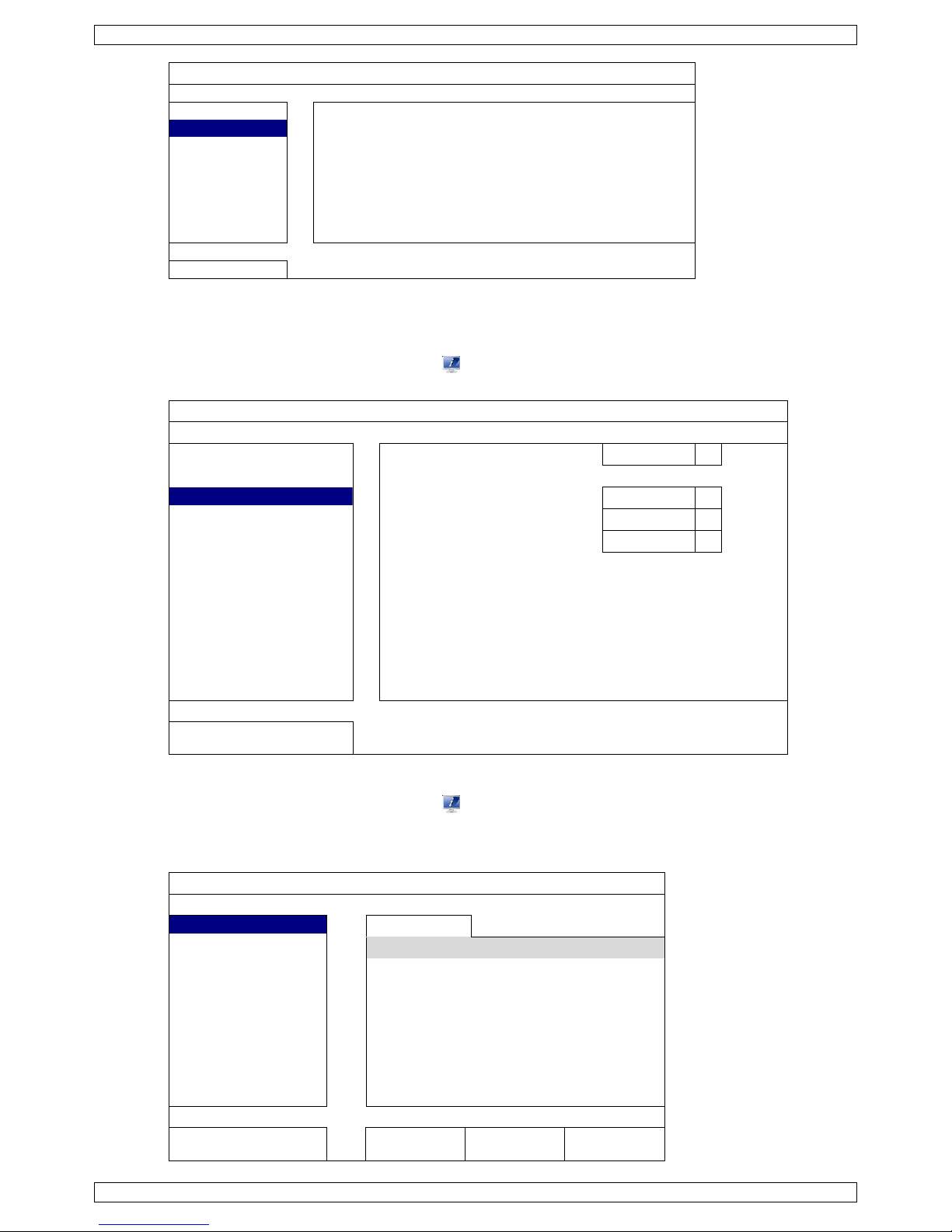
6. User Interface
Refer to the illustrations on page 2 of this manual.
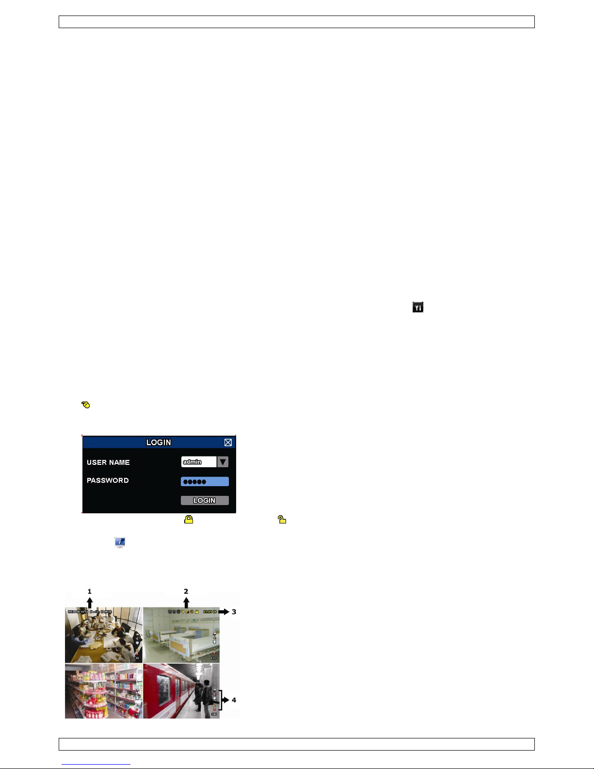
6.1 DVR Access
1. Connect a USB mouse to the mouse port on the DVR front panel, and check if there is a mouse icon
on the screen, indicating the USB mouse is detected properly.
2. Move your mouse to enter the DVR password with the password keypad. The default user name and
password are both admin.
The status will change from (key lock) to (unlock).
Note: You can configure four different user levels with different access privileges in the main menu
(SYSTEM) > ACCOUNT. For more information, refer to User Creation further in this manual.
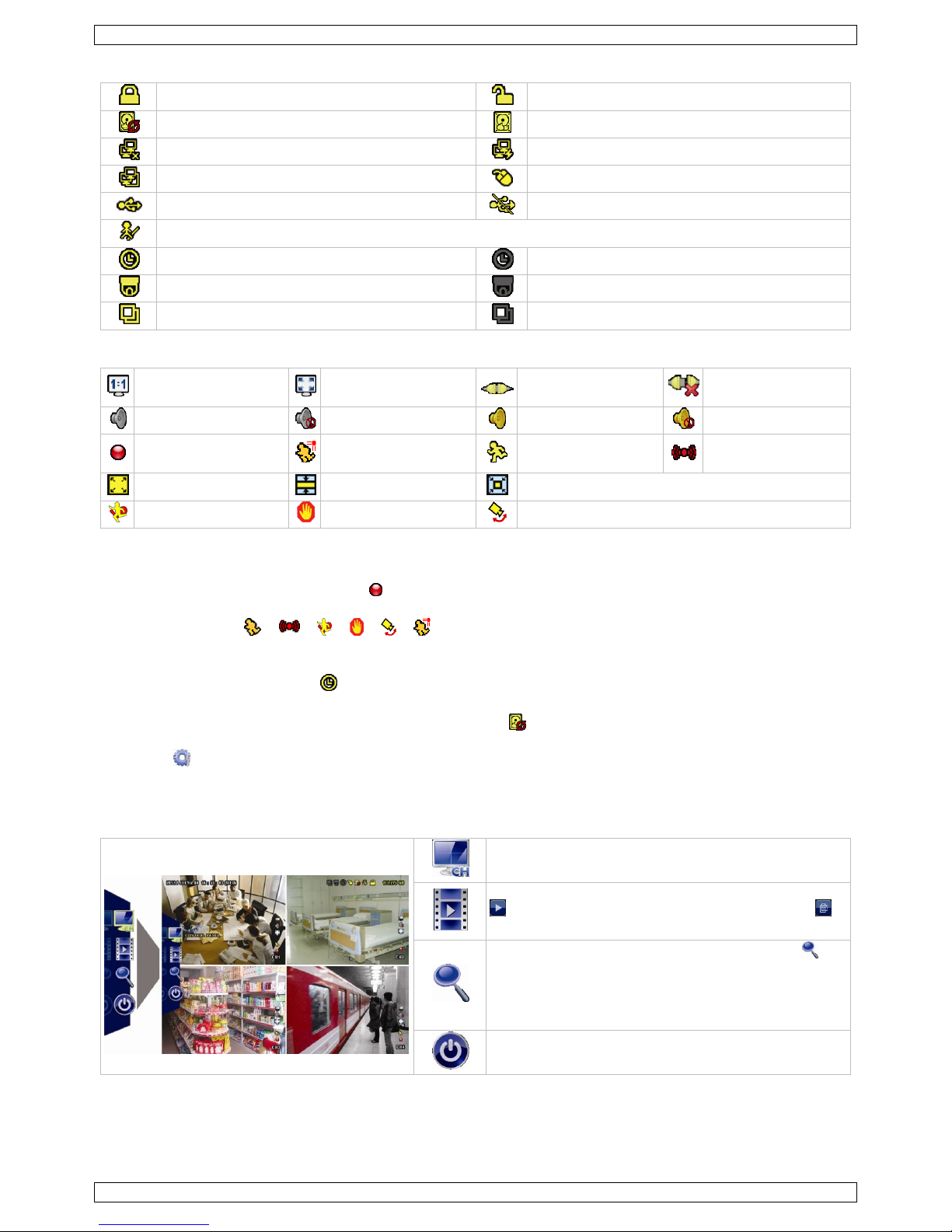
6.2 Live Page
1. system time
2. DVR status bar
3. available HDD capacity
4. channel status bar
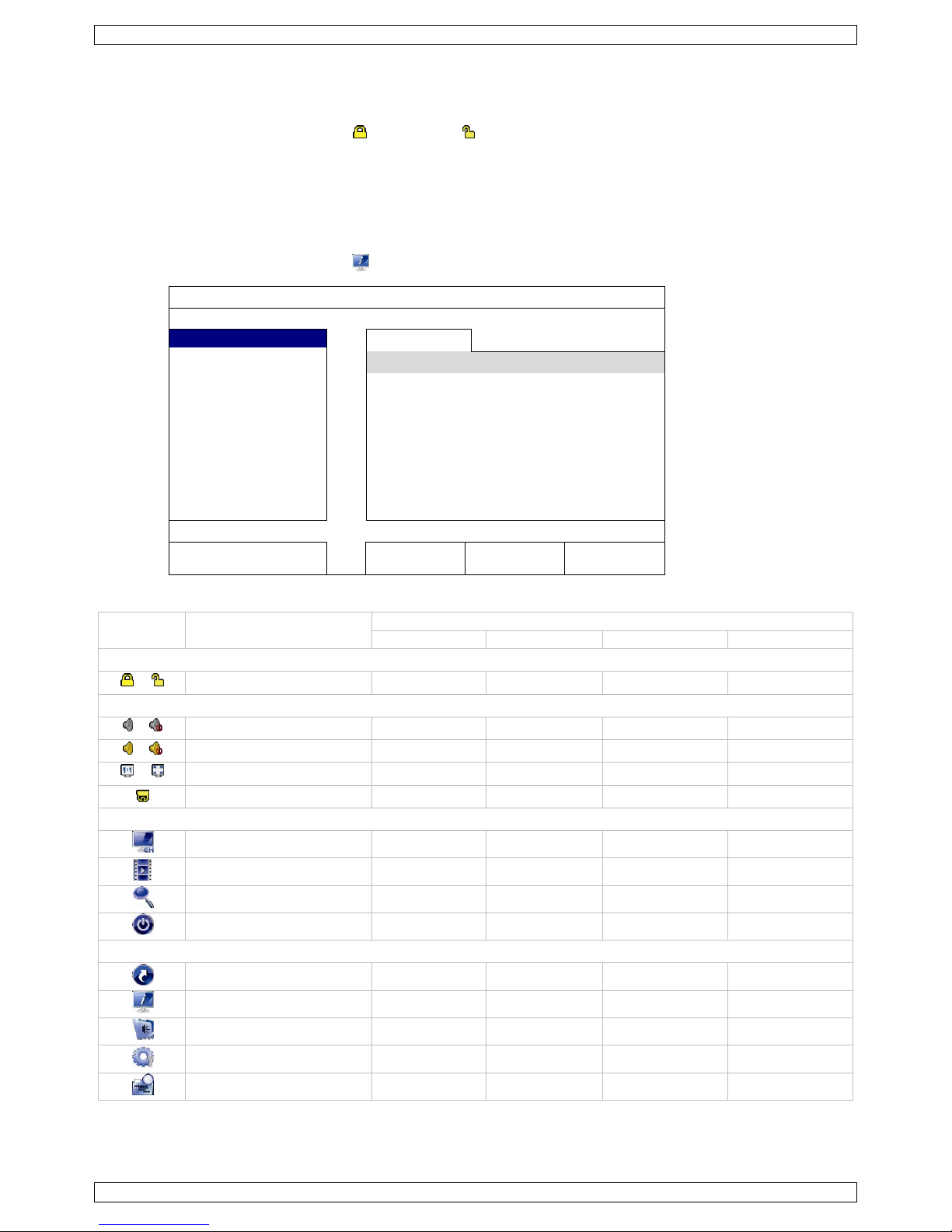
CCTVPROMT1
V. 01 – 25/02/2016 6 ©Velleman nv
DVR Status
key lock
key unlock
overwrite on
overwrite off
internet disconnected
internet connected
local connection
USB mouse connected
USB flash drive/device connected
no USB device connected
IVS on
timer recording on
timer recording off
PTZ mode on
PTZ mode off
sequence mode on
sequence mode off
Channel Status
original size
fit to screen
DCCS connection OK
DCCS connection
failed
live audio on
audio off
audio playback on
audio playback off
recording
human detection
event
motion event
alarm event
record mode: Frame
record mode: Field
record mode: CIF
virtual fence event
one way pass event
scene change event
Icons for Recording
manual recording
By default, manual recording is on ( ) when the DVR is powered on and a HDD is installed.
event recording
The event icons, / / / / / , are shown on the display when their respective events occur
and the related record function is on.
timer recording
When timer recording is on, is displayed on the screen.
HDD overwrite
By default, the HDD overwrite function is set to ON, and is displayed on the screen.
Note: To disable the overwrite function, right-click to display the main menu in the live view window. Then
select (ADVANCED CONFIG) > RECORD > OVERWRITE.
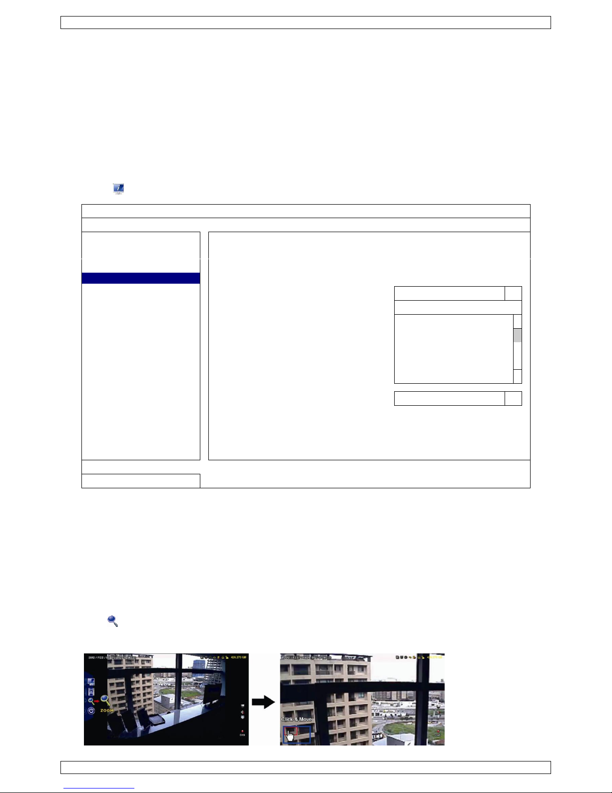
6.3 Quick Menu Bar
Move the mouse pointer to the left of the screen to extend the quick menu bar and show the functions:
Quick Menu (extended)
Click to show the channel switch panel and select the
channel you want.
Click to display the playback control panel, and click
to play the latest recorded video clip, or click
to enter the search list.
Switch to the channel you want first, and click to
enter the zoom-in mode. In this mode, click and drag
the red frame on the bottom left of the screen to
move to the place you want to see. To exit this mode,
click .
Click to show the power off panel to either halt or
reboot the system.
CCTVPROMT1
V. 01 – 25/02/2016 7 ©Velleman nv
6.4 Main Menu
Main menu
QUICK START
Click to set the status display, image
settings, and date & time.
SYSTEM
Click to set the system configurations.
EVENT INFORMATION
Click to enter the event search menu.
ADVANCED CONFIG
Click to set CAMERA, DETECTION,
ALERT, NETWORK, DISPLAY, RECORD,
DEVICES, DCCS, IVS & NOTIFY.
SCHEDULE SETTINGS
Click to set record timer, detection
timer, and alarm timer.
Main Menu Structure
QUICK START
GENERAL
CHANNEL TITLE – EVENT STATUS – DATE DISPLAY – DCCS
DISPLAY – MOUSE SENSITIVITY – AUDIO GAIN – RECORD
CONFIG
TIME SETUP
DATE – TIME – NTP SERVER – FORMAT – SYNC PERIOD –
GMT
DAYLIGHT
EaZy*
SYSTEM
ACCOUNT
TOOLS
LANGUAGE – UPGRADE – NETWORK UPGRADE – BACKUP
CONFIG – RESTORE CONFIG
SYSTEM INFO
BAUD RATE – HOST ID – R.E.T.R. – AUTO KEY LOCK(S) –
CLEAR HDD – RESET DEFAULT – REMOTE CONTROL ID –
DEVICE TITLE – SERIAL TYPE – VIDEO FORMAT – VERSION
BACKUP DATA (USB)
BACKUP LOG (USB)
REGULAR REPORT
AUTO BACKUP
EVENT
INFORMATION
QUICK SEARCH
EVENT SEARCH
HDD INFO
EVENT LOG
ADVANCED
CONFIG
CAMERA
BRIGHTNESS – CONTRAST – SATURATION – HUE – REC –
TIME STAMP DISPLAY – CHANNEL TITLE – REC AUDIO –
ALARM OUT DURATION
DETECTION
LS – SS – TS – MOTION – ALARM – AREA – INTERNAL
ALARM
ALERT
EXT. ALERT – INT. BUZZER – KEY BUZZER – VLOSS
BUZZER – MOTION BUZZER – ALARM BUZZER – HDD
BUZZER – ALARM DURATION (SEC) – HDD NEARLY FULL
(GB) – HDD OVERHEAT ALERT (°C)
NETWORK
WAN – E-MAIL – DDNS – PROTOCOL – EaZy
DISPLAY
FULL SCREEN DURATION – HDD DISPLAY MODE – DISPLAY
OUTPUT – 3D DENOISE – 2D DENOISE – SHARPNESS
RECORD
MANUAL RECORD – EVENT RECORD – TIMER RECORD –
PRE-ALARM RECORD – OVERWRITE – KEEP DATA LIMIT
(DAYS) – RECORD CONFIG – SUBSTREAM RESOLUTION
DEVICES*
DCCS
IVS*
NOTIFY
PUSH VIDEO* – PUSH STATUS – MESSAGE MAIL – VIDEO
MAIL – VIDEO FTP
CCTVPROMT1
V. 01 – 25/02/2016 8 ©Velleman nv
SCHEDULE
SETTINGS
RECORD
DETECTION
ALARM IN
ALARM OUT
PUSH VIDEO
BUZZER
* For selected modes only
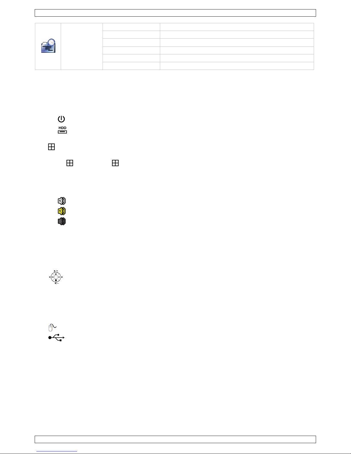
7. Hardware Overview
7.1 Front Panel
LED indicators
o : DVR is powered on.
o : HDD is reading or recording.
1–4: Press the channel number buttons to select the channel to display.
: Press to show the 4-channel display mode.
SEQ: Press to show all screens sequentially in full screen mode. Press again to quit.
P.T.Z. ( + SEQ): Press + SEQ at the same time to enter or exit the PTZ control mode.
SLOW: In playback mode, press to play the recorded file slowly.
ZOOM: Press to enlarge the image of the selected channel (in FRAME or FIELD recording mode).
AUDIO (SLOW + ZOOM): Press SLOW + ZOOM at the same time to select live or playback audio from audio
channel 1-4.
o : live audio from audio channel 1-4 (indicated in white)
o : playback audio from audio channel 1-4 (indicated in yellow)
o : audio channel unselected.
PLAY: Press to playback the latest recorded data.
LIST (Event List Search): Press to quickly search the recorded files by event lists: RECORD / MOTION /
ALARM / TIME / HUMAN DETECTION / IVS / STATISTIC, or select FULL to show all the event logs.
To quickly search the time you want, select QUICK SEARCH. For more details, refer to the full user manual.
MENU: Press MENU to enter the main menu.
ENTER: Press ENTER to confirm the setting.
: Press ▲ / ▼ / ◄ / ► to move up / down / left / right.
In playback mode:
o Press to pause playback.
o Press to stop playback.
o Press to fast forward.
o Press to fast rewind.
: USB port to connect a USB mouse for mouse control
: USB port to connect a USB flash drive for video backup.
Note: Do not connect two USB mice or two USB flash drives simultaneously.
Note: For a list of compatible USB flash drives, please refer to the appendices in the full user manual.
7.2 Rear Panel
INPUT (1–4): Connect to the video connector of a camera.
Note: The DVR will automatically detect the video system of the camera; make sure that the cameras are
properly connected to the DVR and powered on before the DVR is turned on.
VIDEO OUT: BNC.
AUDIO IN (1): Connect to the audio connector of a camera if the camera supports audio recording.
Note: To make a video backup with audio, make sure the camera which supports the audio function is
connected to the video-in channel and audio-in channel. For example, the audio data from audio channel 1
will be recorded with the video data from video channel 1.
AUDIO OUT (1): Mono audio output to connect to a speaker.

CCTVPROMT1
V. 01 – 25/02/2016 9 ©Velleman nv
LAN: Connect to internet by LAN cable.
EXTERNAL I/O: This port is used to connect external devices (such as speed dome cameras, external
alarms, etc.).
HDMI: Connect to the HDMI port of a monitor that supports HDMI video output.
Note: You can use the HDMI and VGA output ports simultaneously for dual video output.
eSATA: Connect to a storage device that supports the eSATA interface. For example, an external hard disk
or a disk array.
Note: Make sure that the disk array supports Linux® to ensure proper functioning.
VGA: Connect to the VGA port of a monitor that supports HDMI video output.
Note: You can use the HDMI and VGA output ports simultaneously for dual video output.
IR: Connect the IR receiver extension line for remote control.
DC 19V: Connect to the supplied adapter.
8. Connection and Setup
8.1 Connecting a Monitor and Camera
1. Obtain a suitable monitor (not included) and connect it to the HDMI video output port on the back of
the DVR.
2. Obtain at least one suitable camera (not included). Each camera needs its own power supply.
3. Connect the video output of the camera to a video input at the back of the DVR (INPUT 1–4). The numbers
next to the input connectors represent the channel number. Connector type is BNC.
4. Power on the camera(s).
8.2 Switching On
Caution:
Before the DVR is powered on, make sure that (1) the cameras are connected and powered on for the
detection of the camera video system to be correct, and (2) an HDMI monitor is connected to the DVR for
correct video output detection.
This device should be operated only with the type of power source indicated on the manufacturer’s label.
Use only the included adapter.
To switch on the DVR:
1. Plug the DC output connector of the included power adapter into the power input (DC 12V) at the back of
the DVR.
2. Plug the included power cable into the adapter input connector and plug the other end into the mains.
3. Switch on the DVR with the power switch on the back of the device. The power LED lights on the front of
the DVR.
Note: To ensure that your DVR works constantly and properly, it is recommended to use an UPS
(Uninterruptible Power Supply, not incl.), for continuous operation.
8.3 Date and Time Setting
Before operating your DVR, please set the date and time on your DVR first.
Note: DO NOT change the date or time of your DVR after the recording function is activated. Otherwise, the
recorded data will be disordered and you will not be able to find the recorded file from backup by time search.
If users change the date or time accidentally when the recording function is activated, it is recommended to
clear all HDD data, and start recording again.
Note: When using the DVR for the first time, leave it powered on for at least 48 hours continuously after the
date and time is set correctly. It prevents DVR time from resetting if the DVR power is disconnected. If the DVR
time resets after power disconnection (for example caused by a power outage), the internal battery may run
down. In that case, you have to replace the internal battery. Please refer to the appendices in the full user
manual for more information.
1. Right-click to enter the DVR password with the password keypad. The default administrator password
is admin.
The status will change from (key lock) to (unlock).
2. Right-click to show the main menu, and select (QUICK START) > TIME SETUP to set the date and time.
CCTVPROMT1
V. 01 – 25/02/2016 10 ©Velleman nv
QUICK START
GENERAL
DATE
2009 / NOV / 17
TIME SETUP
TIME
15 : 35 : 53
DAYLIGHT
NTP SERVER
pool.ntp.org
EaZy FORMAT
Y/M/D
SYNC PERIOD
OFF
GMT
(GMT + 8:00) TAIPEI
EXIT
8.4 Clearing the Hard Disk
It is recommended to clear all data in the hard disk when using this DVR for the first time to ensure the
recorded data are not mixed with other data previously saved in the same hard disk.
1. Right-click to show the main menu, and select (SYSTEM) > SYSTEM INFO > CLEAR HDD.
2. The DVR will reboot when HDD data are cleared. Please refer to the full user manual for more information.
SYSTEM
ACCOUNT
BAUD RATE
2400
TOOLS
HOST ID
000
SYSTEM INFO
R.E.T.R
5
BACKUP DATA
AUTO KEY LOCK(S)
NEVER
BACKUP LOG
CLEAR HDD
HDD-0
REGULAR REPORT
RESET DEFAULT
SUBMIT
REMOTE CONTROL ID
000
DEVICE TITLE
OFFICE
SERIAL TYPE
RS485
VIDEO FORMAT
NTSC
VERSION
1019-1008-1010-1010
EXIT
8.5 Password Setting
1. Right-click to show the main menu, and select (SYSTEM) > ACCOUNT to change the default password of
SUPERVISOR.
2. There are four user levels for different access privileges: SUPERVISOR, POWER USER, NORMAL, and
GUEST. For details, please refer to User Creation further in this manual.
SYSTEM
ACCOUNT
USER LIST
TOOLS
USER NAME
LEVEL
SYSTEM INFO
admin
SUPERVISOR
BACKUP DATA
power
POWER USER
BACKUP LOG
normal
NORMAL
REGULAR REPORT
guest
GUEST
EXIT
ADD
EDIT
DEL
CCTVPROMT1
V. 01 – 25/02/2016 11 ©Velleman nv
9. Basic Operation
9.1 Key Lock / Unlock
To lock or unlock the operation, click (key lock) or (unlock) in the DVR status bar to change the status.
When you unlock the operation, you have to enter a user name and password. The default user name and
password are both admin. These credentials give you access with the highest user level. For more information,
refer to User Creation further in this manual.
9.2 User Creation
Note: This function is only available for SUPERVISOR users.
To create a new user account, select (SYSTEM) > ACCOUNT. The list of users appears on the display.
SYSTEM
ACCOUNT
USER LIST
TOOLS
USER NAME
LEVEL
SYSTEM INFO
admin
SUPERVISOR
BACKUP DATA
power
POWER USER
BACKUP LOG
normal
NORMAL
REGULAR REPORT
guest
GUEST
EXIT
ADD
EDIT
DEL
The access rights for the different user levels are described below:
Function
User level
SUPERVISOR
POWER USER
NORMAL
GUEST
DVR status
/
Key lock/unlock
yes
yes
yes
yes
Channel status
/
Live audio on/off
yes
yes
yes
yes
/
Playback audio on/off
yes
yes
yes
yes
/
Original size / fit to screen
yes
PTZ control
yes
yes
Quick menu bar
Channel selection
yes
yes
yes
yes
Playback
yes
yes
yes
Digital zoom
yes
yes
yes
yes
Power
yes
Main menu
Quick start
yes
System
yes
Event information
yes
Advanced config.
yes
Schedule setting
yes

CCTVPROMT1
V. 01 – 25/02/2016 12 ©Velleman nv
Function
User level
SUPERVISOR
POWER USER
NORMAL
GUEST
Playback control
Fast forward
yes
yes
yes
Fast rewind
yes
yes
yes
/
Play/pause
yes
yes
yes
Stop
yes
yes
yes
Slow playback
yes
yes
yes
/
Previous/next hour
yes
yes
yes
Quick search
yes
yes
yes
9.3 Playback
Note: This function is not available for GUEST users.
Click on the quick menu bar to display the playback control panel, and click to play the latest recorded
video clip, or click to enter the search list.
Refer to the image below:
1
progress bar
4
control bar
2
close
5
event search
3
information bar
Note: There must be at least 8192 images of recorded data for playback to work properly. If not, the device
will stop playback. For example, if the IPS is set to 30, the recording time should be at least 273 seconds
(8192 images / 30 IPS) for the playback to work properly.
Playback Control
Fast forward
Increase the speed for fast forward. Click once to get 4x speed forward, click twice
to get 8x speed, etc. Maximum speed is 32x.
Fast rewind
Increase the speed for fast rewind. Click once to get 4x speed rewind, click twice to
get 8x speed, etc. Maximum speed is 32x.
/
Play/pause
Click to play the latest recorded video clip immediately, click again to pause.
In the pause mode, click once to get one frame forward, and click to get one
frame rewind.
Stop
Click to stop the video playback.
Slow playback
Click once to get 1/4x speed playback, and click twice to get 1/8x speed playback.
/
Previous /
next hour
Click to jump to the next/previous time interval in an hour, for example,
11:00 - 12:00 or 14:00 - 15:00, and start playing the earliest event video clip
recorded during this whole hour.
Repeat
Click to set point A and point B in a video clip, and the system will play only the
specified range in that clip.
Backup
Click to open the backup menu for video backup.
Event Search
Click to quickly search the recorded files by event lists: RECORD / MOTION / ALARM / TIME / HUMAN
DETECTION / IVS / STATISTIC, or select FULL to show all the event logs.
To quickly search the time you want, select QUICK SEARCH. For more details, refer to the full user manual.
Audio Playback
In playback mode, click or on the channel status bar to play or mute audio.
CCTVPROMT1
V. 01 – 25/02/2016 13 ©Velleman nv
Note: To make a video backup with audio, make sure the camera which supports the audio function is
connected to the video-in channel and audio-in channel. For example, the audio data from audio channel 1 will
be recorded with the video data from video channel 1.
9.4 Video Backup
Notes:
This function is only available for SUPERVISOR users.
Before using a USB flash drive, format it to FAT32 format first. For a list of compatible USB flash drives,
please refer to the appendices in the full user manual.
For video backup, use a USB flash drive or back up your data via internet. Do not connect the HDD to your
PC directly.
To back up recorded data, proceed as follows:
1. Select (SYSTEM) > BACKUP DATA (USB).
SYSTEM
ACCOUNT
START DATE
2009/NOV/19
TOOLS
START TIME
08:30:21
SYSTEM INFO
END DATE
2009/NOV/19
BACKUP DATA
END TIME
17:59:29
BACKUP LOG
CHANNEL
3 SELECTED
REGULAR REPORT
ALL
CH1
CH2
CH3
CH4
CH5
HARD DISK
ALL HDD
OUTPUT FILE FORMAT
AVI
TARGET DEVICE
USB DEVICE
BACKUP
SUBMIT
REQUIRE SIZE: 554MB
SUBMIT
EXIT
AVAILABLE SIZE: 3788.0MB
2. Fill in START DATE, START TIME, END DATE, and END TIME to define the period of time for the video data
that you want to back up.
3. Select the video channel(s) that you want to back up.
4. In REQUIRED SIZE, select SUBMIT to calculate the file size of the data selected for backup.
5. In BACKUP, select SUBMIT to start backing up to your USB flash drive.
6. Wait until the “backup successful” message appears.
9.5 Digital Zoom
1. Switch to the channel you want to zoom in on, and move the cursor to the left side of the screen to display
the quick start bar.
2. Click to enter zoom mode.
3. In zoom mode, click and drag the red frame at the bottom left of the screen to move to the area you want
to see.
CCTVPROMT1
V. 01 – 25/02/2016 14 ©Velleman nv
4. To exit, right-click anywhere on the screen.
Note: You need to exit the zoom mode before you can use other DVR functions.
10. Push Video Configuration
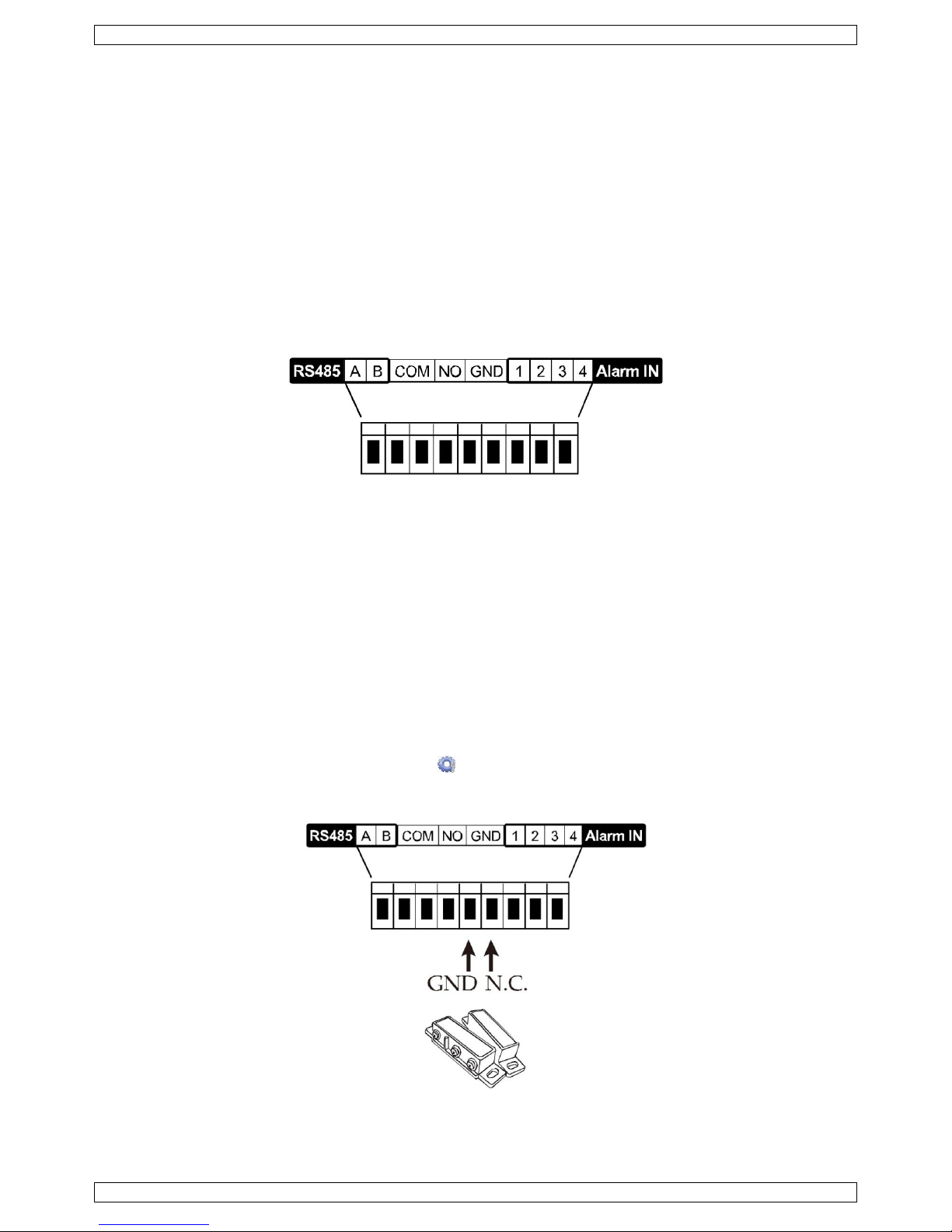
10.1 Pin Connection
This DVR can send notifications to your mobile devices, such as iPhone, iPad, and Android mobile devices, if an
alarm event occurs (push video). However, only certain alarm-in pins support this function.
There are several methods to connect alarm sensors for push video:
via the push video alarm-in terminal
via the external I/O port.
Push Video Alarm-In Terminal
A push video alarm-in terminal is provided on the DVR rear panel. Refer to the image below for the pin
connections that support push video and its corresponding video channel.
Alarm Sensor Connection
Connect the alarm sensor, such as magnetic contacts, to the push video alarm-in terminal or I/O pins that
support push video on the DVR rear panel.
10.2 Configuration
Before configuring push video, make sure that:
The DVR system is set up as described in Connection and Setup.
The DVR is connected to internet and the external access configuration has been completed. Set the DDNS
in following menu: ADVANCED CONFIG – NETWORK – DDNS; set the port in following menu: ADVANCED
CONFIG – NETWORK – WAN; set the port forwarding in the router.
You have installed the EagleEyes app on your iPhone, iPad, or Android mobile devices.
For details, please refer to Mobile Surveillance via EagleEyes.
To configure push video:
1. Right-click to show the main menu and select (ADVANCED CONFIG) > NOTIFY.
2. Set GUARD to ON.
3. Configure your alarm sensor type (normal open or normal closed).
CCTVPROMT1
V. 01 – 25/02/2016 15 ©Velleman nv
Careful! You have to select the opposite type for push video to work correctly.
If your alarm sensor is N.C. (normal closed, alarm goes off when the contact opens), then select
ALARM N.O.
If your alarm sensor is N.O. (normal open, alarm goes off when the contact closes), then select
ALARM N.C.
ADVANCED CONFIG
CAMERA
PUSH VIDEO
PUSH STATUS
MESSAGE MAIL
VIDEO MAIL
VIDEO FTP
DETECTION
RESET ALL GUARD CONNECTION
SUBMIT
ALERT
GUARD TRIGGER BY
ALARM IN 1
NETWORK
CH01
ALARM OFF / INTERNAL ALARM
CH1
DISPLAY
CH02
ALARM OFF
CH2
RECORD
CH03
ALARM N.O.
office
DEVICES
CH04
ALARM OFF
CH4
DCCS
IVS
NOTIFY
MULTICASTING
EXIT
4. Open EagleEyes and add this DVR to the EagleEyes address book.
Note: For more information on EagleEyes operation, please visit www.eagleeyescctv.com.
5. Enable push video.
6. Trigger the input alarm.
7. Receive an event notification and see video.
11. Mobile Surveillance via EagleEyes
EagleEyes is a powerful mobile surveillance program developed by AV TECH Corporation.
Note: For more operations details about EagleEyes, visit http://www.eagleeyescctv.com.
For any comment or question about this program, contact Velleman. Visit www.velleman.eu for contact details.
11.1 Prerequisite
Before installing EagleEyes on your mobile phone for remote surveillance, make sure you have checked the
following:
Your mobile platform is iPhone, iPad, BlackBerry, or Android.
CCTVPROMT1
V. 01 – 25/02/2016 16 ©Velleman nv
You have subscribed to mobile internet services on your phone; the service is available for use on your
phone.
Note: You may be charged for internet access via wireless or 3G networks. For the internet access rates,
contact your local network operator or service provider.
You have noted down the IP address, port number, user name, and password used to access your network
camera via internet.
11.2 Downloading EagleEyes
1. Connect to www.eagleeyescctv.com from your mobile device.
Note: Do not download EagleEyes from your computer.
2. Select Products > Software > Mobile app to access the EagleEyes introduction page.
3. Select your platform (iOS, BlackBerry, or Android) and download the program you need.
Note: This DVR is compatible only with iPhone, iPad, BlackBerry, and Android mobile devices.
4. Follow the on-screen instructions for downloading.
When the download is completed, EagleEyes is installed automatically on your mobile device.
Note: For more information about the configuration of this program, read the related instructions on the
download page.
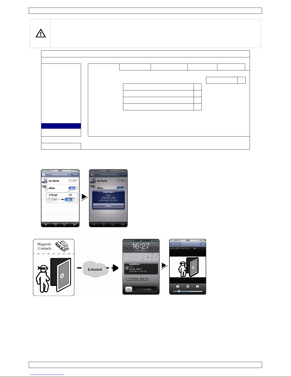
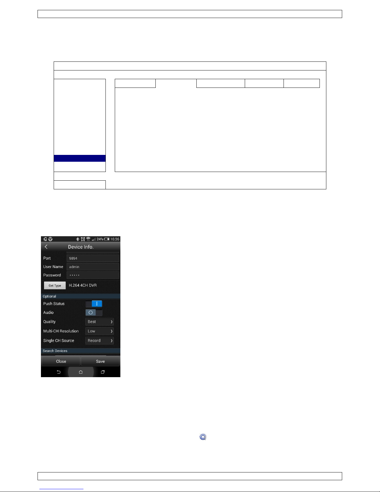
12. Setting Up Push Video
This DVR series supports instant event notifications to your iPhone, iPad, or Android mobile device with
EagleEyes installed. When a human is detected by a human detection camera or the external alarm device, the
DVR will immediately receive alarm signals and send them to your mobile device.
12.1 Prerequisite
Before setting up push video, make sure you have checked the following:
You have an iPhone, iPad, or Android mobile device with EagleEyes installed. For more details, see
Downloading EagleEyes.
A human detection camera is connected to CH1, or an external alarm device is connected to the push video
alarm-in terminal on the rear panel. To record alarm occurrences, make sure you also have a camera
connected. Refer to Push Video Configuration for details on video channels and alarm pins.
The event record function of your DVR is enabled.
The motion detection function of your DVR is enabled.
Your DVR is connected to internet. For details, refer to
http://www.surveillance-download.com/user/CMS.pdf.
12.2 Enabling Push Video
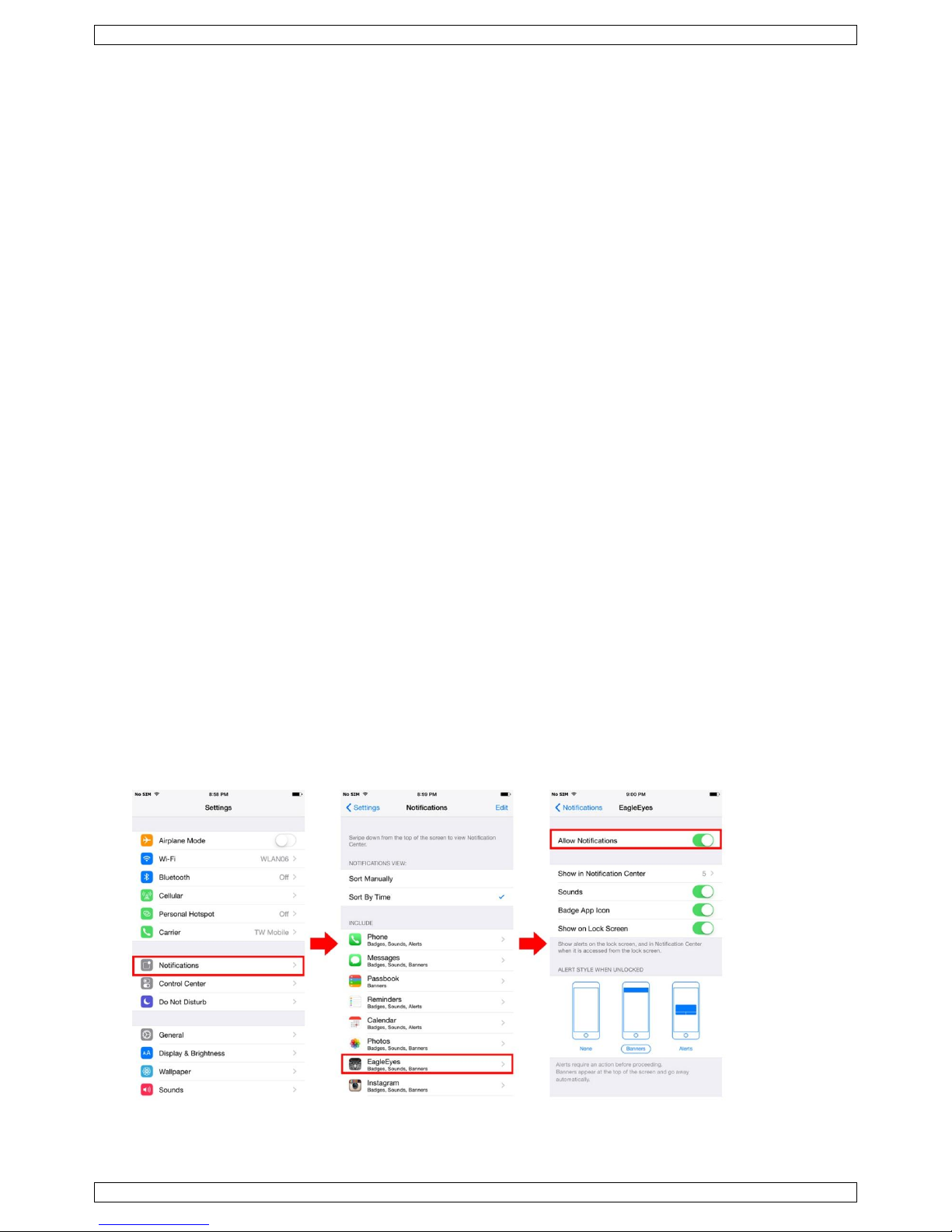
From iPhone or iPad
1. In the iPhone/iPad main menu, select Settings > Notifications.
2. Select EagleEyes and make sure Notification Center is set to ON.
CCTVPROMT1
V. 01 – 25/02/2016 17 ©Velleman nv
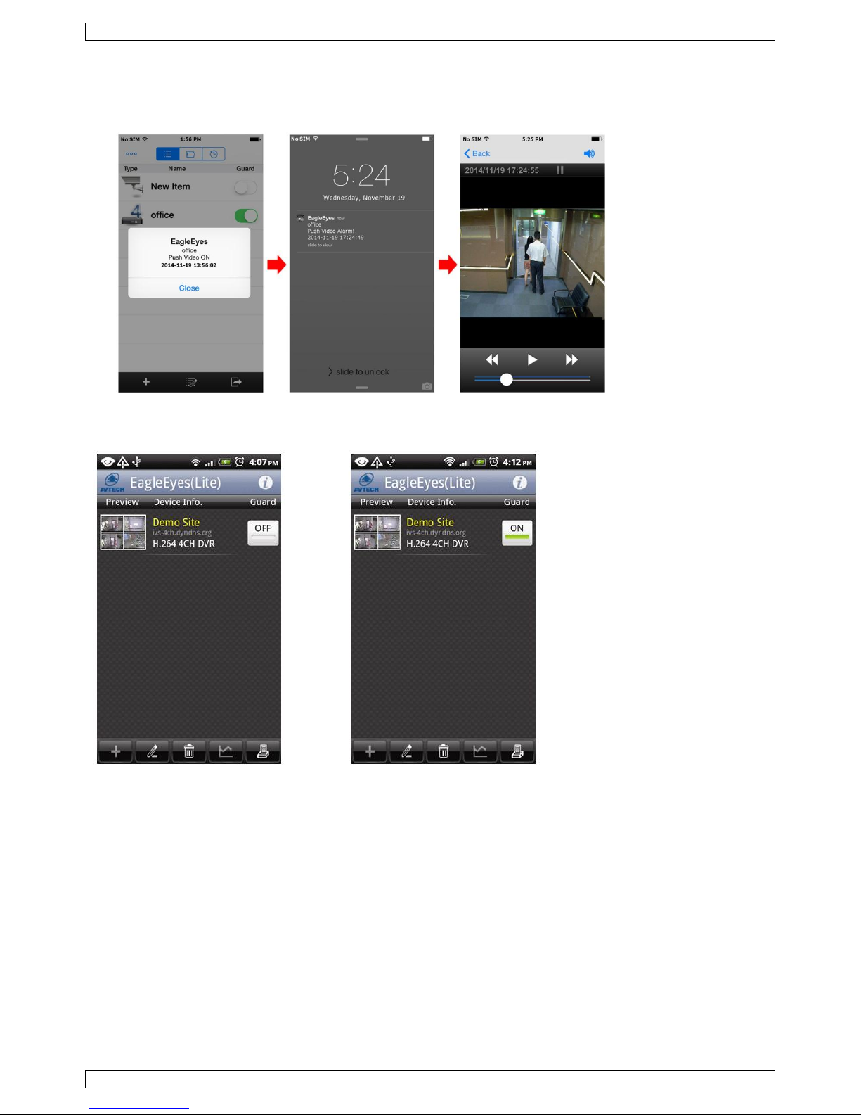
3. Open EagleEyes and switch the Push Video button to ON. You will receive a message that push notification
(push video) is enabled.
4. Return to the main menu of your iPhone/iPad.
You will receive event notifications when there is a human detection or an alarm event. Select Launch to
play the recorded clip immediately.
From Android Mobile Device
In the address book, switch Guard from OFF to ON.
CCTVPROMT1
V. 01 – 25/02/2016 18 ©Velleman nv
13. Push Status
Note: Before using this function, make sure that you have configured EagleEyes* and that the Guard has been
enabled. For details, please refer to chapter 12. Setting Up Push Video.
ADVANCED CONFIG
CAMERA
PUSH VIDEO
PUSH STATUS
MESSAGE MAIL
VIDEO MAIL
VIDEO FTP
DETECTION
ACTION
ON
ALERT
EVENT
ALL
NETWORK
VIDEO LOSS
DISPLAY
HDD FULL
RECORD
POWER ON
DEVICES
HDD (CLEAR / NO HDD / OVER TEMPERATURE)
DCCS
NET LOGIN
IVS
KEY UNLOCK
NOTIFY
UPS
MULTICASTING
SYSTEM ABNORMAL
EXIT
1. Set ACTION to ON.
2. Select the system event(s) you want to get notified via your mobile device.
3. Activate the push status of the device in the EagleEyes application. Go to CONFIGURATION – OPTIONAL –
PUSH STATUS.
14. Set Flow Counting – Virtual Fence – One-Way Pass
Note: Before using the IVS function, make sure that event recording is enabled on your DVR.
Intelligent Video Surveillance (IVS) is the advanced application for motion detection, but more precise and
smarter. It can be applied to different situations with one of the following three modes: FLOW COUNTING,
VIRTUAL FENCE or ONE WAY.
On the DVR, right-click to show the main menu, and select (ADVANCED CONFIG) > IVS.
CCTVPROMT1
V. 01 – 25/02/2016 19 ©Velleman nv
ADVANCED CONFIG
CAMERA
IVS1
IVS2
IVS3
IVS4
DETECTION
CAMERA
CH3
ALERT
IVS MODE
FLOW COUNTING
NETWORK
DISPLAY LINE
OFF
DISPLAY
SENSITIVITY
07
RECORD
RESET COUNT
SUBMIT
DEVICES
VIRTUAL FENCE AREA
SETUP
DCCS
SCENE CHANGE
OFF
IVS
SCENE CHANGE LEVEL
MIDDLE
NOTIFY
EXIT
CAMERA: Select the camera channel that you want to use with the IVS function.
IVS MODE: Select one of the following three modes depending on your environment:
Mode
Description
FLOW COUNTING
A virtual detection line is set to detect the moving direction of pedestrians for flow
counting.
VIRTUAL FENCE
A virtual detection line is set to detect intruders crossing the detection line, and an
alarm will be triggered.
ONE WAY
A virtual detection line is set to detect intruders from the specified direction, and an
alarm will be triggered.
DISPLAY LINE: Select to display the detection line for IVS on the screen or not.
SENSITIVITY: Set the sensitivity for IVS from 00-15. The larger the value, the more sensitive the IVS
will be.
RESET COUNT: Click SUBMIT to reset the flow counting number to 0 when the IVS mode is set to FLOW
COUNTING and activated.
VIRTUAL FENCE AREA: Click SETUP to draw the detection line for IVS, and set the detection direction. This
area setting is the detection base for IVS MODE.
SCENE CHANGE: Select ON to trigger a motion event when the camera is moved and the camera scene
changes. At the same time, the icon will also be shown on the screen in addition to the motion icon .
SCENE CHANGE LEVEL: Set the detection sensitivity for SCENE CHANGE to HIGH, MIDDLE or LOW.
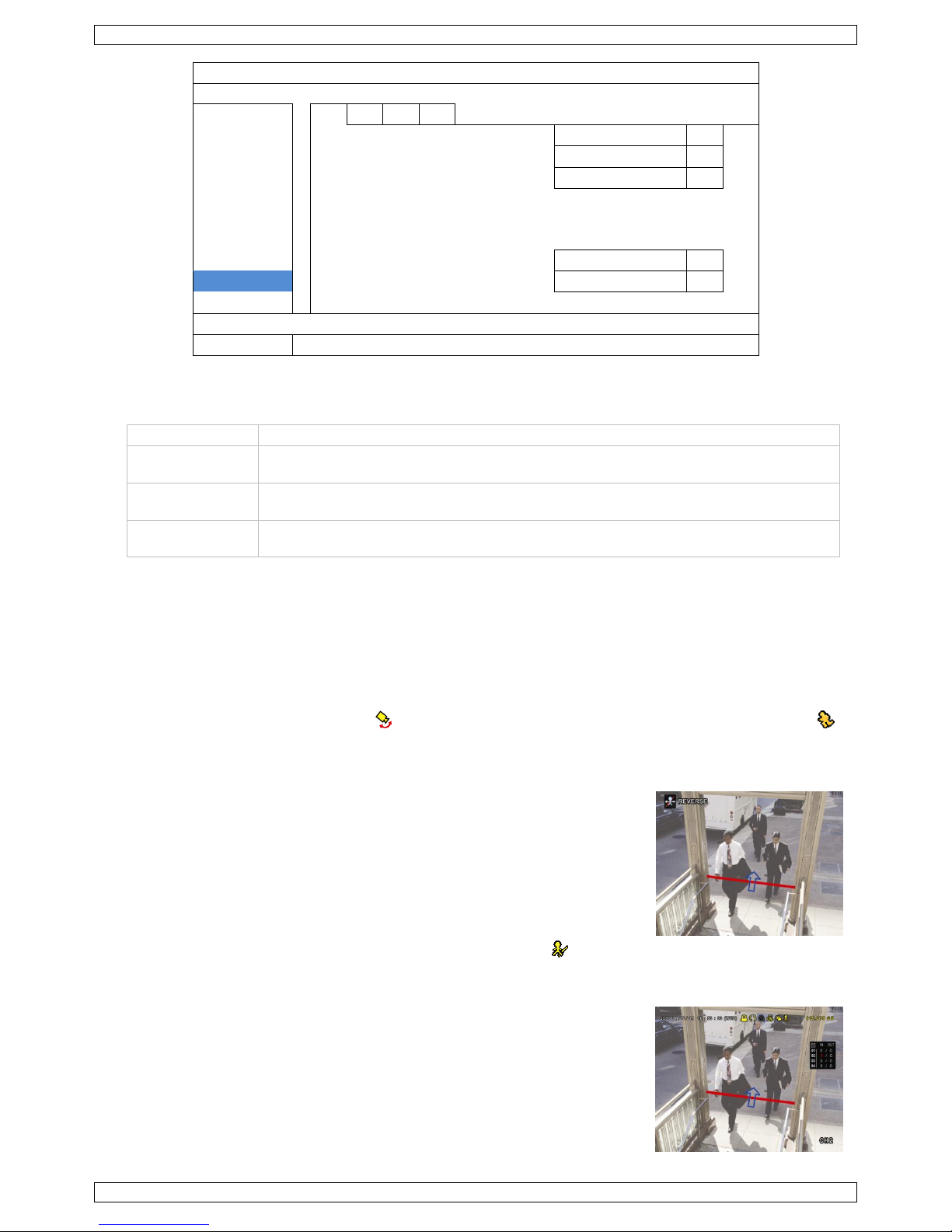
14.1 Flow Counting
1. Go to VIRTUAL FENCE AREA to draw a detection line with your mouse,
and decide the detection direction by selecting REVERSE.
2. Finish the IVS setting and return to the live view. The IVS icon will
be shown on the status bar.
3. Click it to show the flow counting panel as follows. When anyone walks
across the detection line, the system will determine if the movement is
in or out, and add one count to the corresponding channel on the flow
counting panel.
IN People coming from the opposite direction to the arrow mark.
OUT People coming from the same direction as the arrow mark.
CCTVPROMT1
V. 01 – 25/02/2016 20 ©Velleman nv
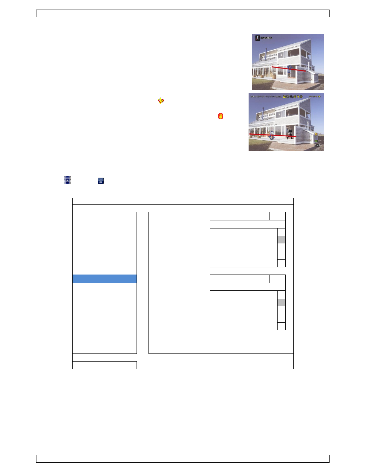
14.2 Virtual Fence / One-Way Pass
1. Go to VIRTUAL FENCE AREA to draw a detection line with your mouse,
and decide the detection direction by selecting REVERSE.
2. Finish the IVS setting and return to the live view.
When anyone walks across the detection line, the system will
determine his movement is in or out.
VIRTUAL FENCE An event is triggered when anyone walks across
the detection line from any direction, and is shown on the screen.
ONE WAY An event is triggered when anyone walks across the
detection line from the opposite direction of the arrow mark, and is
shown on the screen.
14.3 IVS Statistics
1. In the live view, move the mouse to the left to display the quick menu bar.
2. Click and then to enter the event search menu.
3. Select STATISTIC.
LIST
QUICK SEARCH
CHANNEL
3 SELECTED
RECORD
ALL
MOTION
CH1
ALARM
CH2
TIME
CH3 HUMAN DETECTION
CH4
IVS
FULL
STATISTIC
EVENT TYPE
3 SELECTED
ALL
INFLOW
OUTFLOW
VIRTUAL FENCE
ONEWAY
MOTION
TIME
2010/MAY/17
STATISTIC
SUBMIT
EXIT
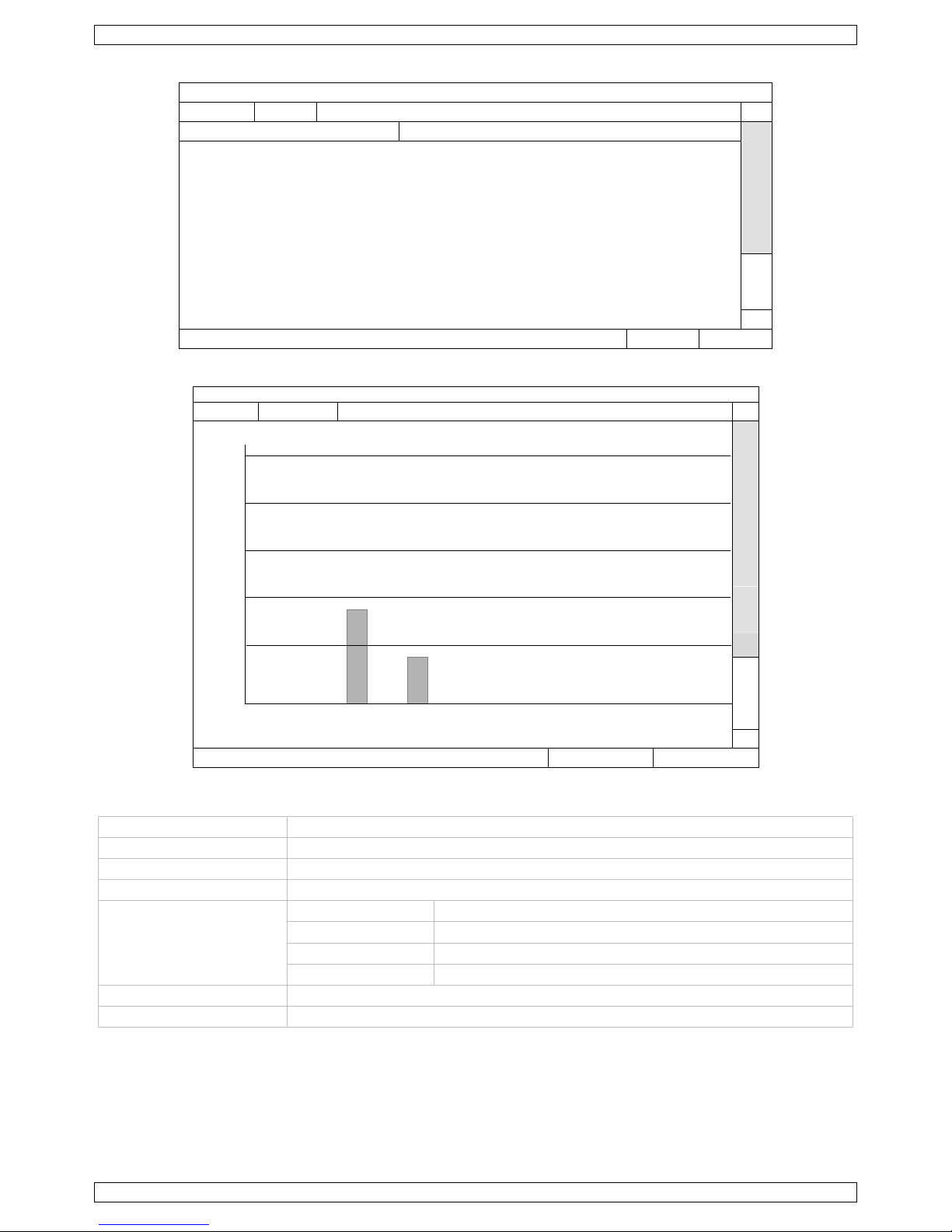
4. Set all the criteria you want to search, and click SUBMIT in STATISTIC to show the event statistics.
5. Click LIST or CHART to see the statistics in list or chart form.
6. To switch to the month or year view, click DAY at the bottom.
CCTVPROMT1
V. 01 – 25/02/2016 21 ©Velleman nv
List View
IVS STATISTIC
LIST
CHART
HOUR
COUNT
00:00 – 00:59
0
01:00 – 01:59
0
02:00 – 02:59
0
03:00 – 03:59
0
04:00 – 04:59
0
05:00 – 05:59
0
06:00 – 06:59
0
07:00 – 07:59
0
08:00 – 08:59
3
09:00 – 09:59
9 2010/MAY/17
DAY
EXIT
Chart View
IVS STATISTIC
LIST
CHART
30
COUNT
24
18 12
6
0
0 1 2 3 4 5 6 7 8 9 10
11
12
13
14
15
16
17
18
19
20
21
22
23
HOUR
2010/MAY/17
DAY
EXIT
15. Technical Specifications
video format
TVI / AHD / 960H
video compression
H.264
video input
4 channels
video output
HDMI (1080p), VGA (max. 1920 x 1080 pixels) & BNC composite video
maximum recording rate
(PAL)
1080P
1920 x 1080 pixels @ 60 fps
720P
1280 x 720 pixels @ 120 fps
960H
960 x 576 pixels @ 100 fps (PAL)
frame
704 × 576 pixels @ 100 fps (PAL)
adjustable recording speed
–
image quality setting
super best – best – high – normal

CCTVPROMT1
V. 01 – 25/02/2016 22 ©Velleman nv
hard disk storage
built-in 1 TB hard disk drive
HDD quick cleaning
quick clean-up of the "index system" of the recorded files. 1 TB in under 2 seconds
recording mode
manual / timer / motion / network / alarm-controlled
multiplex operation
live display, record, playback, backup and network
audio I/O
1x audio in, 1x audio out (mono)
motion detection area
16 × 12 grids per channel
motion detection
sensitivity
high – normal – low
pre-alarm recording
yes
backup device
USB 2.0 flash drive (for backup and firmware updates)
mobile surveillance
EagleEyes software
smart phones
push video &
status
on iPad®, iPod® Touch, iPhone® and Android®
phone
remote login via all smart phone platforms (Apple®, Android®
BlackBerry®, Nokia® Symbian and Windows® Mobile)
computer
CMS (Central
Management
System)
24 channel CMS software for Windows OS (free)
video viewer software on Windows® and Mac®
web browser
Internet Explorer®, Firefox®, Google Chrome® and
Safari® via Java, QuickTime® or VLC plug-in
Ethernet
10/100BASE-T, supports remote control and LiveView via Ethernet
network connection
supports TCP/IP, PPPoE, DHCP and DDNS function
IR remote control
remote control DVR and PTZ (DVRRC4, not incl.)
PTZ control
yes (via RS-485)
alarm I/O
4 inputs / 1 output
digital zoom
2 x (live & playback)
key lock
yes
video loss detection
yes
camera title
up to 6 characters
video adjustments
hue / colour / contrast / brightness
date display format
YY/MM/DD, DD/MM/YY, MM/DD/YY, and off
power source
19 VDC
power consumption
< 40 W
daylight saving
yes
operating temperature
10-40 °C (50-104 °F)
system recovery
system auto recovery after power reconnected
dimensions
375 x 61 x 281 mm
cameras
water resistance
IP66
pick-up element
1/2.7" CMOS image sensor
number of pixels
1930 (H) x 1088 (V)
resolution
1080P video
digital signal processor
Techpoint chip
min. illumination
0.1 lux
IR LEDs
12
max. IR projection
distance
15 m
S/N ratio
> 48 dB (AGC off)
lens
f 3.6 mm / F 1.8
lens angle
96°
AGC
yes
white balance
automatic / user / push / 8000K / 6000K / 4200K / 3200K
video output
1.0 Vpp composite, 75 ohm

CCTVPROMT1
V. 01 – 25/02/2016 23 ©Velleman nv
audio
no
power supply
12 VDC
current consumption
max. 200 mA (IR on)
operating temperature
20 °C to 40 °C - RH max. 95 %
dimensions
198 x 65 x 68 mm
weight
315 g
Use this device with original accessories only. Velleman nv cannot be held responsible in the event
of damage or injury resulting from (incorrect) use of this device. For more info concerning this
product and the latest version of this manual, please visit our website www.velleman.eu. Download
the multilingual version of this document from www.velleman.eu. The information in this manual is
subject to change without prior notice.
All registered trademarks and trade names are properties of their respective owners and are used only for the
clarification of the compatibility of our products with the products of the different manufacturers. Windows,
Windows Mobile are registered trademarks of Microsoft Corporation in the United States and other countries.
Mac, iPad, iPhone, iOS are trademarks of Apple Inc., registered in the U.S. and other countries. Android is a
trademark of Google Inc. The Trademark BlackBerry® is owned by Research In Motion Limited and is registered
in the United States and may be pending or registered in other countries. Velleman NV is not endorsed,
sponsored, affiliated with or otherwise authorized by Research In Motion Limited. Symbian is a registered
trademark of Symbian Software Ltd, Symbian Ltd. Linux® is the registered trademark of Linus Torvalds in the
U.S. and other countries.
© COPYRIGHT NOTICE
The copyright to this manual is owned by Velleman nv. All worldwide rights reserved. No part of this
manual may be copied, reproduced, translated or reduced to any electronic medium or otherwise without the
prior written consent of the copyright holder.
CCTVPROMT1
V. 01 – 25/02/2016 24 ©Velleman nv
KORTE HANDLEIDING
1. Inleiding
Aan alle ingezetenen van de Europese Unie
Belangrijke milieu-informatie betreffende dit product
Dit symbool op het toestel of de verpakking geeft aan dat, als het na zijn levenscyclus wordt
weggeworpen, dit toestel schade kan toebrengen aan het milieu. Gooi dit toestel (en eventuele
batterijen) niet bij het gewone huishoudelijke afval; het moet bij een gespecialiseerd bedrijf
terechtkomen voor recyclage. U moet dit toestel naar uw verdeler of naar een lokaal recyclagepunt
brengen. Respecteer de plaatselijke milieuwetgeving.
Hebt u vragen, contacteer dan de plaatselijke autoriteiten betreffende de verwijdering.
Dank u voor uw aankoop! Lees deze handleiding grondig door voor u het toestel in gebruik neemt. Werd het
toestel beschadigd tijdens het transport, installeer het dan niet en raadpleeg uw dealer.
OPMERKING: Dit document is een beknopte installatiehandleiding. Voor meer informatie, raadpleeg de
volledige handleiding die beschikbaar is op de meegeleverde cd-rom. Download de meertalige versie van dit
document via www.velleman.eu.
Deze doe-het-zelf beveiligingsset is de ideale oplossing voor de bewaking van uw huis of zaak.
Het systeem bestaat uit 2 full HDCCTV- of TVI- (High Definition Transport Video Interface) camera's met IRleds, 20 m voedings-/signaalkabel voor elke camera en een digitale full HD 4-kanaal videorecorder, die in
1080P-formaat kan opnemen. Het systeem is uitbreidbaar met andere anderen HDCCTV-camera's, AHDcamera's of 960 H analoge videocamera's.
De eigenschappen van dit systeem zijn: opname door bewegingswaarneming, back-up naar een harde schijf
van 1 TB (meegeleverd), via netwerk of USB via meertalige gebruikersinterface.
Ingebouwde VGA-interface, 1 audio-ingangen en 1 audio-uitgang, ingangen voor extern alarm.
Bediening via USB-muis met grafische gebruikersinterface op het scherm. IVS-functie met
mensenstroomtelling, virtuele muur en registratie eenrichtingsverkeer.
Geavanceerde bewaking via smartphone dankzij de gratis EagleEyes-software voor mobiele telefoon met Push
Status- en Push Video-functie.
De DVR stuurt een bericht als er een probleem is met het systeem.
Bij een alarm worden de beelden onmiddellijk van kanaal 1 naar het geactiveerde mobiele toestel gestuurd.
2. Veiligheidsvoorschriften
OPGELET
ELEKTROCUTIEGEVAAR
OPGELET:
Stel het toestel niet bloot aan regen of vocht, om het risico op elektrische schokken te voorkomen. Gebruik het
toestel enkel met de voedingsspanning zoals vermeld op het toestel. Wij zijn niet aansprakelijk voor schade bij
verkeerd gebruik van dit toestel.
De bliksemschicht met pijlpunt in een driehoek waarschuwt de gebruiker voor de aanwezigheid van
niet-geïsoleerde gevaarlijke spanning in de behuizing van het systeem, die zo hoog kan zijn dat er
een risico van elektrische schokken bestaat.
Het uitroepteken in een driehoek, zoals afgebeeld op het systeem, is bedoeld om de gebruiker attent
te maken op belangrijke gebruiks- en onderhoudsinstructies in deze gebruikershandleiding.
Houd dit toestel uit de buurt van kinderen en onbevoegden.
Elektrocutiegevaar bij het openen van de behuizing. Raak geen kabels aan die onder stroom staan
om dodelijke elektrische schokken te vermijden. Laat het onderhoud van het toestel over aan een
vakman.
Trek de stekker uit het stopcontact voordat u het toestel reinigt of als u het niet gebruikt. Houd de
voedingskabel altijd vast bij de stekker en niet bij de kabel.
Demonteer of open dit toestel NOOIT tenzij anders vermeld in deze handleiding. Er zijn geen
onderdelen in het toestel die door de gebruiker gerepareerd kunnen worden. Contacteer uw verdeler
voor eventuele reserveonderdelen.

CCTVPROMT1
V. 01 – 25/02/2016 25 ©Velleman nv
Dit toestel valt onder beschermingsklasse I (voorzien van een beschermende aarding ingebouwd in
het stroomsnoer). De stekker mag enkel aangesloten worden op een stopcontact met aarde. Elke
onderbreking van de beschermende geleider, aan de binnenzijde of aan de buitenzijde van het
toestel, is gevaarlijk. Opzettelijke onderbreking is verboden.
3. Algemene richtlijnen
Raadpleeg de Velleman® service- en kwaliteitsgarantie achteraan de uitgebreide handleiding (zie
meegeleverde cd-rom).
Gebruik het toestel enkel binnenshuis. Bescherm het toestel tegen regen, vochtigheid en
opspattende vloeistoffen. Plaats nooit objecten gevuld met vloeistof op of naast het toestel.
Bescherm tegen stof en extreme temperaturen. Zorg ervoor dat de ventilatieopeningen niet
verstopt geraken. Voor voldoende luchtcirculatie, voorzie een ruimte van minstens 2.5 cm
tussen het toestel en elk ander object.
Bescherm tegen schokken. Vermijd brute kracht tijdens de bediening van het toestel.
Leer eerst de functies van het toestel kennen voor u het gaat gebruiken.
Om veiligheidsredenen mag u geen wijzigingen aan het apparaat aanbrengen. Schade door wijzigingen die
de gebruiker heeft aangebracht aan het toestel valt niet onder de garantie.
Gebruik het toestel enkel waarvoor het gemaakt is. De garantie vervalt automatisch bij ongeoorloofd
gebruik.
De garantie geldt niet voor schade door het negeren van bepaalde richtlijnen in deze handleiding en uw
dealer zal de verantwoordelijkheid afwijzen voor defecten of problemen die hier rechtstreeks verband mee
houden.
Bewaar deze handleiding voor verdere raadpleging.
Installeer en gebruik dit toestel NIET voor illegale praktijken en respecteer ieders privacy.
4. Eigenschappen
compressieformaat: H.264 real-time
tribrid-video-ingang: IP-camera, AHD-, TVI- & 960H-video
bewaking op afstand via iPad®, iPhone®, BlackBerry®, Windows Mobile®, Symbian® en Android®
verbinding met smartphone via 3G/4G of Wifi
bediening via GUI (Graphical User Interface) en USB-muis
intelligente videoanalyse: 4 kanalen
o virtuele muur: waarneming van alle indringers die de virtuele muur overtreden
o mensenstroom: een virtuele muur bepaalt de richting van de mensenstroom
automatische geïntegreerde dynamische domeinnaamservice (DDNS): gratis
inhoud:
o 1 x DVR met push status-functie
o 2 x IR-kleurencamera: CAMTVI1
o 2 x camerakabels van 20 m:
o 1 x 19 V-voedingsadapter
o 1 x high-efficiency DC-DC convertor voor de DVR en de camera's: DVR4/DC
meertalige OSD: Engels, Frans, Nederlands, Duits, Portugees, Spaans, Tsjechisch, Hongaars, Grieks,
Chinees en Vietnamees
gebruikershandleiding: Engels
beknopte handleiding: Engels, Nederlands, Frans, Spaans, Duits
* muis niet meegeleverd
Opmerking: dit toestel vereist een basiskennis van netwerkinstallaties
CCTVPROMT1
V. 01 – 25/02/2016 26 ©Velleman nv
5. De hardware installeren
Raadpleeg de afbeeldingen op pagina 2 van deze handleiding.
Een monitor aansluiten
Sluit een geschikte monitor (niet meegelev.) aan op de HDMI- of VGA-uitgangspoort aan de achterkant van de
DVR.
De voeding aansluiten
1. Sluit de DC-stekker van de meegeleverde voedingsadapter aan op de 19VDC-ingang aan de achterkant van
de DVR.
WAARSCHUWING: gebruik enkel de meegeleverde voedingsadapter.
2. Sluit het toestel via de meegeleverde stroomkabel aan op het lichtnet. Schakel de DVR nog niet in.
Een camera aansluiten
1. U kunt tot 4 camera's aansluiten (2 camera's meegeleverd). Elke camera heeft een eigen voeding nodig.
2. Sluit de video-uitgang van de camera aan op een video-ingang aan de achterkant van de DVR. Het nummer
naast de aansluiting duidt op het kanaalnummer. Het aansluittype is BNC (kabels meegeleverd).
Audio aansluiten
1. De DVR heeft vier geluidsingangen. Sluit de geluidsuitgang van een geluidsbron aan op de geluidsingang
van de DVR. Zorg ervoor dat u het geluidskanaal aansluit op het correcte videokanaal. Het aansluittype is
BNC.
2. Er is ook een geluidsuitgang. Indien nodig, sluit een extern geluidstoestel (bijv. een luidspreker) aan. Het
aansluittype is BNC.
Een lokaal netwerk (LAN) aansluiten
Sluit de DVR via een netwerkkabel aan op een LAN-netwerk. Gebruik hiervoor een stekker van het type 8P8C
(RJ45). Om de netwerkverbinding in te stellen, druk op de MENU-knop en selecteer . Voor meer informatie,
raadpleeg de uitgebreide handleiding op de meegeleverde cd-rom.
6. Gebruikersinterface
Raadpleeg de afbeeldingen op pagina 2 van deze handleiding.
6.1 DVR-toegang
1. Sluit een USB-muis aan op de muispoort op het DVR-frontpaneel, en controleer of er een muispictogram
verschijnt op het scherm wat aangeeft dat de USB-muis is gedetecteerd.
2. Beweeg de muis om het wachtwoord van de DVR in te voeren met het toetsenbord. De standaard
gebruikersnaam en het standaard wachtwoord zijn beiden admin.
De status verandert van (vergrendeld) naar (ontgrendeld).
Opmerking: U kunt 4 verschillende gebruikersniveaus instellen met verschillende gebruikersrechten in het
hoofdmenu (SYSTEM) > ACCOUNT. Voor meer informatie, zie verder in deze handleiding onder
Gebruikersaccounts aanmaken.
6.2 Live-weergave
1. systeemtijd
2. DVR-statusbalk
3. beschikbare HDD-capaciteit
4. kanaalstatusbalk

CCTVPROMT1
V. 01 – 25/02/2016 27 ©Velleman nv
DVR-status
toetsvergrendeling actief
toetsvergrendeling inactief
harde schijf overschrijven
harde schijf niet overschrijven
niet met internet verbonden
Internetverbinding
lokale verbinding
USB-muis aangesloten
USB flash drive / apparaat aangesloten
geen USB-apparaat aangesloten
IVS ingeschakeld
timeropname ingeschakeld
timeropname uitgeschakeld
PTZ-modus ingeschakeld
PTZ-modus uitgeschakeld
sequentiemodus ingeschakeld
sequentiemodus uitgeschakeld
Kanaalstatus
originele grootte
passend op scherm
DCCS-aansluiting
geslaagd
DCCS-aansluiting
mislukt
live-geluid
ingeschakeld
geluid uitgeschakeld
geluidsweergave
ingeschakeld
geluidsweergave
uitgeschakeld
opname
er wordt een
beweging
waargenomen
beweging
alarm
opnamemodus: Frame
opnamemodus: Field
opnamemodus: CIF
virtuele muur
'One-Way Pass'
camerapositie veranderen
Opnamesymbolen
manuele opname
Standaard is de manuele opnamefunctie ( ) ingeschakeld en de harde schijf geïnstalleerd.
opname na bewegingsdetectie
De symbolen / / / / / worden op het scherm weergegeven (afhankelijk van het event).
timeropname
Wanneer de timeropname actief is, verschijnt het symbool op het scherm.
harde schijf overschrijven
Standaard is deze functie ingeschakeld en verschijnt het symbool op het scherm.
Opmerking: Om de functie 'harde schijf overschrijven" uit te schakelen, klik met de rechtermuisknop, om
het hoofdmenu op de Live-weergavevenster weer te geven. Selecteer vervolgens (ADVANCED CONFIG)
> RECORD > OVERWRITE.
6.3 Snelmenubalk
Beweeg de muispointer naar links in het scherm om het snelmenu te openen en de volgende functies weer te
geven:
Snelmenu (geopend)
Klik om het kanaalkeuzevenster weer te geven en het
gewenste kanaal te selecteren.
Klik om het afspeelpaneel weer te geven, en klik
om de laatst opgenomen videoclip af te spelen, of klik
om de zoeklijst te openen.
Stel eerst het gewenste kanaal in, en klik om de
inzoommodus te openen. Klik en sleep het rode kader
(linksonder) om in te zoomen. Klik op om opnieuw
uit te zoomen.
Klik om het uitschakelmenu weer te geven en het
toestel uit te schakelen of opnieuw op te starten.

CCTVPROMT1
V. 01 – 25/02/2016 28 ©Velleman nv
6.4 Hoofdmenu
Hoofdmenu
QUICK START
Klik om de statusweergave, de beelden,
de datum en het uur in te stellen.
SYSTEM
Klik om de systeemconfiguratie in te
stellen.
EVENT INFORMATION
Klik om naar het zoekmenu voor events
te gaan.
ADVANCED CONFIG
Klik om CAMERA, DETECTION, ALERT,
NETWORK, DISPLAY, RECORD,
DEVICES, DCCS, IVS & NOTIFY in te
stellen.
SCHEDULE SETTINGS
Timerinstellingen detectie en opname.
Structuur hoofdmenu
QUICK START
GENERAL
CHANNEL TITLE – EVENT STATUS – DATE DISPLAY – DCCS
DISPLAY – MOUSE SENSITIVITY – AUDIO GAIN – RECORD
CONFIG
TIME SETUP
DATE – TIME – NTP SERVER – FORMAT – SYNC PERIOD –
GMT
DAYLIGHT
EaZy*
SYSTEM
ACCOUNT
GEREEDSCHAP
LANGUAGE – UPGRADE – NETWORK UPGRADE – BACKUP
CONFIG – RESTORE CONFIG
SYSTEM INFO
BAUD RATE – HOST ID – R.E.T.R. – AUTO KEY LOCK(S) –
CLEAR HDD – RESET DEFAULT – REMOTE CONTROL ID –
SERIAL TYPE – VIDEO FORMAT – VERSION
BACKUP DATA (USB)
BACKUP LOG (USB)
REGULAR REPORT
AUTO BACKUP
EVENT
INFORMATION
QUICK SEARCH
EVENT SEARCH
HDD INFO
EVENT LOG
ADVANCED
CONFIG
CAMERA
BRIGHTNESS – CONTRAST – SATURATION – HUE – REC –
TIME STAMP DISPLAY – CHANNEL TITLE – REC AUDIO –
ALARM OUT DURATION
DETECTION
LS – SS – TS – MOTION – ALARM – AREA – INTERNAL
ALARM
ALERT
EXT. ALERT – INT. BUZZER – KEY BUZZER – VLOSS
BUZZER – MOTION BUZZER – ALARM BUZZER – HDD
BUZZER – ALARM DURATION (SEC) – HDD NEARLY FULL
(GB) – HDD OVERHEAT ALERT (°C)
NETWORK
WAN –E-MAIL – DDNS – PROTOCOL - EaZy
DISPLAY
FULL SCREEN DURATION – HDD DISPLAY MODE – DISPLAY
OUTPUT – 3D DENOISE – 2D DENOISE – SHARPNESS
RECORD
MANUAL RECORD – EVENT RECORD – TIMER RECORD –
PRE-ALARM RECORD – OVERWRITE – KEEP DATA LIMIT
(DAYS) – RECORD CONFIG – SUBSTREAM RESOLUTION
DEVICES*
DCCS
IVS*
NOTIFY
PUSH VIDEO – PUSH MESSAGE – MESSAGE MAIL – VIDEO
MAIL – VIDEO FTP
CCTVPROMT1
V. 01 – 25/02/2016 29 ©Velleman nv
SCHEDULE
SETTINGS
RECORD
DETECTION
ALARM IN
ALARM OUT
PUSH VIDEO
BUZZER
* Enkel voor de geselecteerde modi
7. Beschrijving
7.1 Voorkant
LED-indicatoren
o : DVR is ingeschakeld.
o : Harde schijf speelt bestanden af of neemt bestanden op.
1–4: Druk op een cijfer, om het overeenstemmende kanaal te selecteren.
: 4-kanaals weergavemodus
SEQ: Druk op SEQ om alle kanalen achtereenvolgens op het volledige scherm weer te geven. Druk
nogmaals om de functie te verlaten.
P.T.Z. ( + SEQ): Druk op + gelijktijdig op + SEQ om in PTZ-modus te gaan of te verlaten.
SLOW: In afspeelmodus klikt u om het opgenomen bestand traag af te spelen.
ZOOM: Druk op ZOOM om het beeld in het geselecteerde kanaal te vergroten (in FRAME- of FIELD-
opnamemodus).
AUDIO (SLOW + ZOOM): Druk op SLOW + ZOOM tegelijk om live of bestandsaudio te selecteren vanaf
audiokanaal 1- 4.
o : live audio vanaf audiokanaal 1-4 (wit)
o : Audio afspelen vanaf audiokanaal 1-4 (geel)
o : audiokanaal uitgeschakeld.
PLAY: Druk om het laatst opgenomen bestand af te spelen.
LIST (Zoeklijst): Druk om snel te zoeken in de opgeslagen bestanden volgens event: RECORD / MOTION /
ALARM / TIME / HUMAN DETECTION / IVS / STATISTIC. Selecteer de optie FULL om alle events weer te
geven.
Selecteer QUICK SEARCH om snel naar datum te zoeken. Raadpleeg de uitgebreide handleiding voor meer
details.
MENU: Druk op MENU om het hoofdmenu weer te geven.
ENTER: Druk op ENTER om de instelling te bevestigen.
: Druk op ▲ / ▼ / ◄ / ► om naar boven / onder / links / rechts te gaan.
In afspeelmodus:
o Druk op om de weergave te onderbreken.
o Druk op om de weergave af te spelen.
o Druk op om vooruit te spoelen.
o Druk op om terug te spoelen.
: USB-poort, om een USB-muis aan te sluiten.
: USB-poort, om een USB-geheugenstick voor video-backup aan te sluiten.
Opmerking: Sluit nooit 2 USB-muizen of 2 USB-geheugensticks gelijktijdig aan.
Opmerking: Raadpleeg de bijlagen in de uitgebreide handleiding voor een lijst met compatibele USB-
geheugensticks.
7.2 Achterkant
INPUT (1–4): Video-aansluiting voor de camera.
Opmerking: De DVR detecteert het videosysteem van de camera automatisch. Zorg ervoor dat de
camera's correct met de DVR en voedingsbron verbonden zijn, voordat u de DVR inschakelt.
VIDEO OUT: BNC.

CCTVPROMT1
V. 01 – 25/02/2016 30 ©Velleman nv
AUDIO IN (1): Sluit aan op de audio-aansluiting van een camera, wanneer de camera audio-opnamen
ondersteunt.
Opmerking: Om een video back-up te maken, zorg ervoor dat de camera, die de audiofunctie ondersteunt,
op het video-in- en de audio-in-kanaal aangesloten is. Bijvoorbeeld, de audio van audiokanaal 1 zal
opgeslagen worden met de videogegevens van videokanaal 1.
AUDIO OUT (1): Voor het aansluiten van een luidspreker met mono audio-uitgang.
LAN: LAN-aansluiting.
EXTERNAL I/O: Deze poort wordt gebruikt voor het aansluiten van externe toestellen (speed dome
camera's, externe alarmtoestellen, enz.).
HDMI: Sluit aan op de HDMI-poort van een monitor, die HDMI-video-uitgang ondersteunt.
Opmerking: U kunt de HDMI- en VGA-uitgangspoorten gelijktijdig gebruiken voor een dubbele videouitgang.
eSATA: Sluit aan op een opslagapparaat dat de eSATA-interface ondersteunt. Bijvoorbeeld, een externe
harde schijf of een disk array.
Opmerking: Zorg ervoor dat de disk array Linux® ondersteunt voor een goede werking.
VGA: Sluit aan op de VGA-poort van een monitor, die een HDMI-video-uitgang ondersteunt.
Opmerking: U kunt de HDMI- en VGA-uitgangspoorten gelijktijdig gebruiken voor een dubbele videouitgang.
IR: Sluit de extensiekabel aan voor de IR-afstandsbediening.
DC 19V: Sluit aan op de meegeleverde voedingsadapter.
8. Aansluiting en instelling
8.1 Een monitor en camera aansluiten
1. Sluit een compatibele monitor (niet meegeleverd) aan op de HMDI-uitvoerpoort achteraan op de DVR.
2. Sluit minstens één compatibele camera aan (niet meegeleverd). Elke camera heeft een eigen voeding nodig.
3. Sluit de video-uitgang van de camera aan op de video-ingang achteraan de DVR (INPUT 1–4). De nummers
naast de ingangsaansluitingen duiden op het kanaalnummer. Het aansluittype is BNC.
4. Schakel de camera('s) in.
8.2 Inschakelen
Opgelet:
Alvorens de DVR in te schakelen, zorg ervoor dat (1) de camera's en voedingsbron aangesloten zijn, en dat
een HDMI-monitor op de DVR aangesloten is.
Gebruik dit toestel enkel met een compatibele voedingsbron (zie label). Gebruik enkel de meegeleverde
voedingsadapter.
De DVR inschakelen:
1. Steek de DC-stekker van de voedingsadapter in de 12 VDC-ingang achteraan de DVR.
2. Koppel de meegeleverde voedingskabel aan op de ingangsaansluiting van de adapter en koppel het andere
uiteinde aan het lichtnet.
3. Schakel de DVR in met de voedingsschakelaar achteraan het toestel. De voedingsled op het frontpaneel
licht op.
Opmerking: Om er zeker van te zijn dat uw DVR constant en correct functioneert, is het aan te raden om een
noodstroomvoeding (UPS, niet meegelev.) te gebruiken, voor een constante werking.
8.3 Datum en tijd instellen
Voordat u de DVR gebruikt, stel eerst de datum en de tijd in.
Opmerking: Verander NOOIT de datum en tijd nadat u de opnamefunctie geactiveerd hebt. Anders raakt de
volgorde van de opgenomen gegevens dooreen en kunnen de opgenomen bestanden later niet worden
teruggevonden. Verandert u de datum of het uur onopzettelijk na het activeren van de opnamefunctie, wis dan
alle gegevens van de harde schijf en herbegin met de opname.
Opmerking: Bij het eerste gebruik laat u de DVR, na datum- en tijdinstelling, best gedurende 48 uur
ingeschakeld. Zo wordt de DVR-tijdsinstelling niet gewist bij het ontkoppelen van de DVR. Wanneer de
tijdinstelling gewist wordt na het ontkoppelen van de voeding (bijvoorbeeld door stroomuitval), dan kan de
batterij leeg raken. Is dit het geval, vervang de interne batterij. Voor meer informatie, raadpleeg de bijlagen in
de uitgebreide handleiding.
 Loading...