How it Works
Log In / Sign Up
Buy Points
How it Works
FAQ
Contact Us
Questions and Suggestions
Users
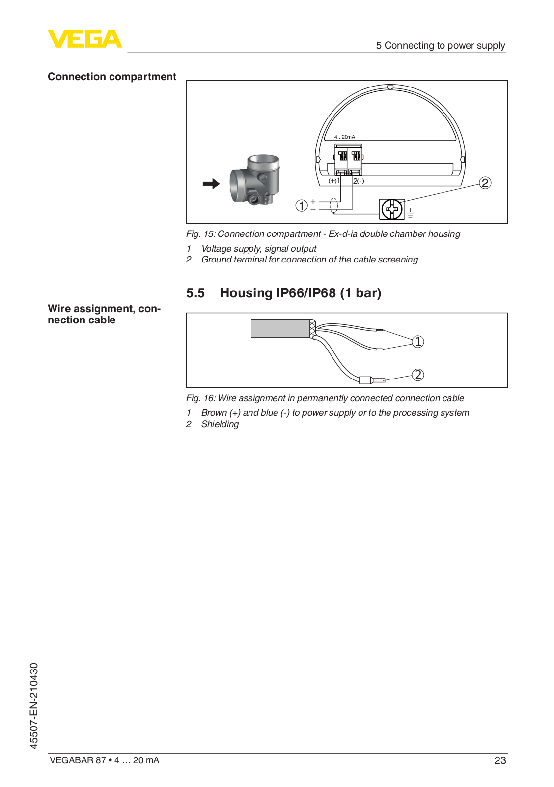
VEGA
Loading...
V
VAIS3
VE 241
VE 24250
VE 322
VE 34062
VE 362
VE 40075
VE 50320
VE 51310
VE80150
VEGABAR
2
VEGABAR 12
2
VEGABAR 14
4
VEGABAR 15
VEGABAR 17
3
VEGABAR 18
VEGABAR 19
VEGABAR 20
VEGABAR 21
VEGABAR 24
VEGABAR 25
VEGABAR 28
VEGABAR 29
VEGABAR 38
VEGABAR 39
2
VEGABAR 40
2
VEGABAR 41
2
VEGABAR 42
VEGABAR 44
2
VEGABAR 50
VEGABAR 51
6
VEGABAR 52
8
VEGABAR 53
6
VEGABAR 54
9
VEGABAR 55
3
VEGABAR 60
VEGABAR 61
VEGABAR 63
2
VEGABAR 64
5
VEGABAR 65
5
VEGABAR 66
5
VEGABAR 67
3
VEGABAR 74
VEGABAR 75
VEGABAR 80
VEGABAR 80 Series
VEGABAR 81
22
VEGABAR 82
23
VEGABAR 83
20
VEGABAR 86
13
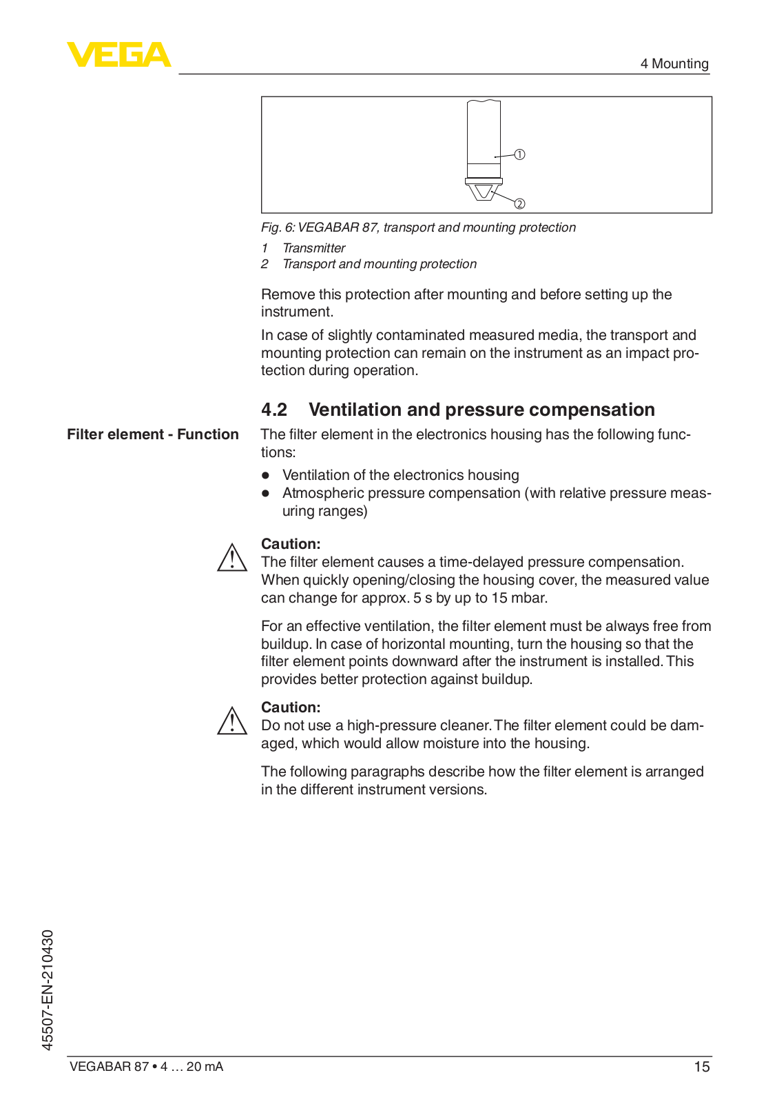
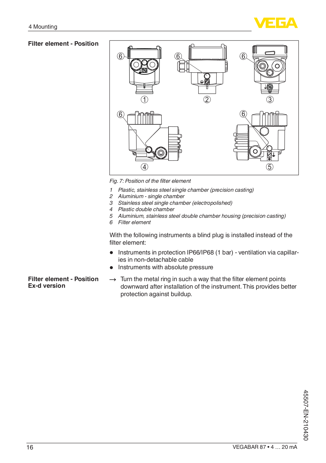
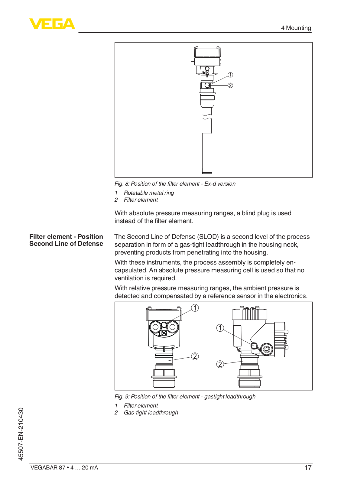
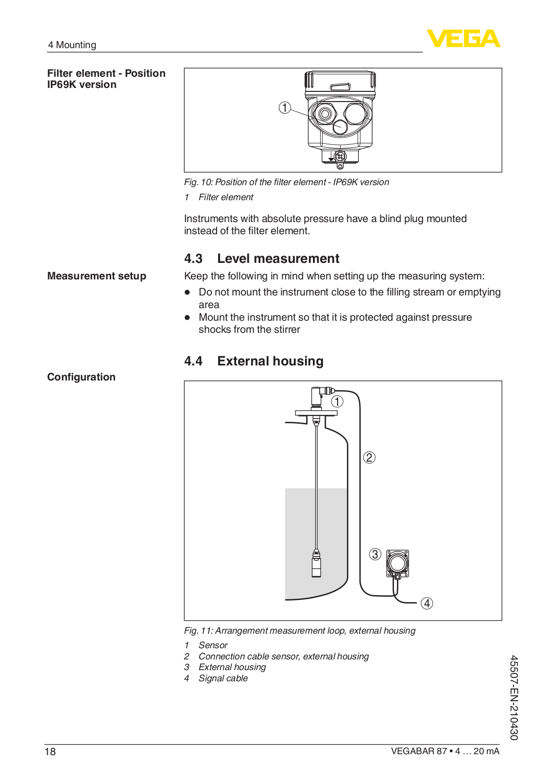
VEGABAR 87
14
VEGABAR series 80
VEGABOX 01
VEGABOX 02
VEGABOX 03
VEGACAL
VEGACAL 60 Series
2
VEGACAL 62
5
VEGACAL 63
10
VEGACAL 64
7
VEGACAL 65
6
VEGACAL 66
7
VEGACAL 67
3
VEGACAL 69
3
VEGACAL External housing
VEGACAL series 60
VEGACAP
VEGACAP 27
4
VEGACAP 35
2
VEGACAP 60 Series
VEGACAP 62
5
VEGACAP 63
7
VEGACAP 64
5
VEGACAP 65
6
VEGACAP 66
5
VEGACAP 67
4
VEGACAP 69
3
VEGACAP 82-98
VEGACAP 98
2
VEGACAP series 60
VEGACOM 557
VEGACONNECT 2
VEGACONNECT 3
VEGACONNECT 4
2
Vegadif 34
2
Vegadif 35
Vegadif 44
Vegadif 45
Vegadif 51
VEGADIF 55
2
VEGADIF 65
12
VEGADIF 85
2
VEGADIS 11
VEGADIS 12
VEGADIS 175
VEGADIS 176
VEGADIS 176 Ex
VEGADIS 363
VEGADIS 371 Ex
VEGADIS 50 Ex
Loading...
Loading...
Nothing found
VEGABAR 87
Operating Instructions
76 pgs
4.74 Mb
0
Operating Instructions Manual
84 pgs
3.5 Mb
0
Operating Instructions Manual
76 pgs
1.68 Mb
0
Quick Setup Guide
24 pgs
1.69 Mb
0
Quick Setup Manual
20 pgs
975.17 Kb
0
User Manual [ru]
20 pgs
441.91 Kb
0
User Manual [ru]
56 pgs
3.07 Mb
0
User Manual [ru]
20 pgs
707.73 Kb
0
User Manual [ru]
80 pgs
5.07 Mb
0
User Manual [ru]
88 pgs
5.37 Mb
0
User Manual [ru]
68 pgs
3.72 Mb
0
User Manual [ru]
84 pgs
5.36 Mb
0
User Manual [ru]
16 pgs
507.43 Kb
0
User Manual [ru]
72 pgs
4.13 Mb
0
Table of contents
Loading...
VEGA VEGABAR 87 Operating Instructions
...
VEGA Operating Instructions
Download
Specifications and Main Features
Frequently Asked Questions
User Manual
Download
Loading...
+
53
hidden pages
Unhide
You need points to download manuals.
1 point = 1 manual.
You can buy points or you can get point for every manual you upload.
Buy points
Upload your manuals