

Page 1
in
out
Operating Instructions
VEGASTAB 692 MD
Level and Pressure
12 34
56 78
on
VEGASTAB 692 MD
13 14 15
910 11
17 18 20 21 22
12
23 24 25 26 27 28
Ser. No.
12345678
16
out
in
Page 2
Safety information, Note Ex area
Safety information
Please read this manual carefully, and also take
note of country-specific installation standards
(e.g. the VDE regulations in Germany) as well
as all prevailing safety regulations and accident prevention rules.
For safety and warranty reasons, any internal
work on the instruments, apart from that involved in normal installation and electrical connection, must be carried out only by qualified
VEGA personnel.
2 VEGASTAB 692 MD
Note Ex area
Please note the attached safety instructions
containing important information on installation
and operation in Ex areas.
These safety instructions are part of the operating instructions and come with the Ex approved instruments.
Page 3

Contents
Contents
Safety i nformation ........................................................................ 2
Note Ex a rea ................................................................................ 2
1 Product description
1.1 Function and configuration ................................................ 4
1.2 Scope of delivery ............................................................... 4
1.3 Ex area ............................................................................... 4
1.4 Features ............................................................................. 4
1.5 Sensor choice .................................................................... 4
1.6 Technical dat a .................................................................... 5
1.7 Dimensions......................................................................... 6
2 Mounting and installation instructions ................................ 7
3 Electrical connection
3.1 Connection instructions ..................................................... 8
3.2 Connection diagram ........................................................... 9
3.4 Installation examples of HART® sensors ....................... 10
4 Setup
4.1 General information on HART® multidrop ........................... 11
4.2 Procedure......................................................................... 11
4.3 Address assignment with VVO ....................................... 12
5 Diagnosis
5.1 Maintenance ..................................................................... 14
5.2 Fault signal........................................................................ 14
5.3 Failure diagnostics ........................................................... 14
5.4 Repair ............................................................................... 14
VEGASTAB 692 MD 3
Page 4

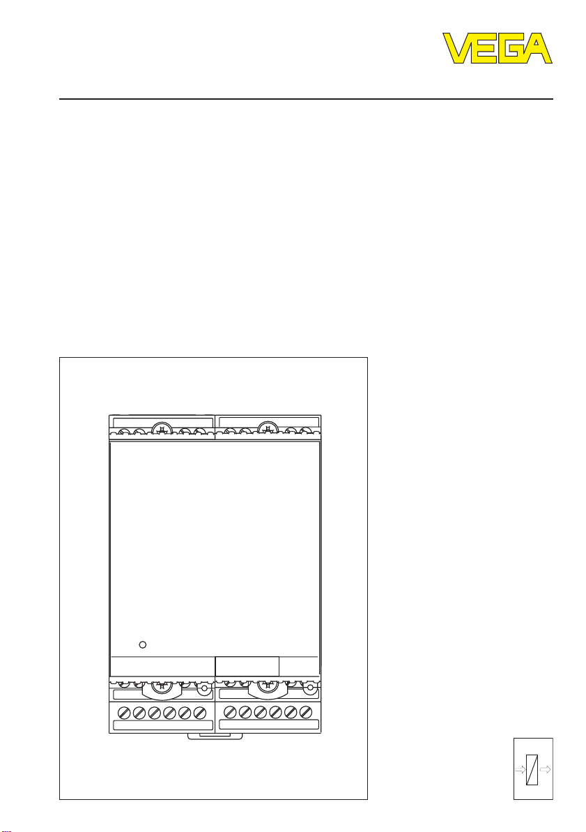
1 Product description
Product description
1.1 Function and configuration
VEGASTAB 692 MD is a power supply unit
for connection of up to 15 VEGA sensors
(HART® two-wire sensors in Multidrop mode).
Function
VEGASTAB 692 MD provides a galvanically
separated supply circuit for up to 15 VEGA
sensors (HART® two-wire loop-powered in
Multidrop mode). The power supply for the
sensors is 17 … 25 V DC depending on the
number of connected sensors. VEGASTAB
692 MD delivers up to 60 mA constant current (15 sensors with 4 mA each) and is
open-circuit and short-circuit proof (current
limitation at approx. 200 mA). The instrument
has an RS 232 interface for communication
with the software Visual VEGA (VV) or VEGA
Visual Operating (VVO) via the
VEGACONNECT 3 interface adapter.
Configuration
VEGASTAB 692 MD is a module unit with
plug-in socket suitable for carrier rail mounting EN 50022.
1.2 Scope of delivery
1.3 Ex area
This power supply unit is not approved for
use in Ex areas.
It must neither be installed in hazardous
areas nor be used for power supply of sensors in these areas.
1.4 Features
- Power supply unit for up to 15 HART® sensors (two-wire loop-powered in Multidrop
mode).
- Digital transmission of measured values
(HART® protocol, Multidrop mode).
- Input voltage range 20 … 250 V AC,
20 … 72 V DC.
- Galvanically separated and overload,
short-circuit or open-circuit proof circuit.
- Integrated HART® resistance.
- RS 232 interface via VEGACONNECT 3 for
connection to a modem or PC.
- Communication with Visual VEGA (VV) and
VEGA Visual Operating (VVO).
1.5 Sensor choice
The following VEGA HART® sensors can be
connected to the unit:
- VEGASTAB 692 MD
- Plug-in socket
- Coded pins, bonding jumpers
- VEGACONNECT 3
- Operating instructions VEGASTAB 692 MD
- Operating instructions VEGACONNECT 3
- Operating instructions remote parameter
adjustment
4 VEGASTAB 692 MD
- VEGAPULS series 40 and VEGAPULS
series 50 radar sensors.
- VEGAFLEX series 50 sensors with guided
microwaves.
- VEGASON series 50 ultrasonic sensors
- Series D80 pressure transmitters and
VEGABAR 40
Make sure that only VEGA HART® sensors in
two-wire loop-powered version (in Multidrop
mode) are used.
It is not possible to connect sensors of other
manufacturers.
Page 5
Product description
1.6 Technical data
Power supply
Operating voltage/Power consumption U
Output or measured data input
Num ber 1 x 24 V output or digital measured data input
Type of measured data input active two-wire input, digital (HART® protocol),
Sensor type up to 15 VEGA two-wire loop-powered HART
Output voltage approx. 17 … 24 V DC
Output constant current max. 60 mA (15 sensors with 4 mA each)
Current limitation at approx. 200 mA, short-circuit proof
Connection cable 2-wire standard cable (screening is
max. cable length 1000 m
max. resistance per wire 15 Ohm
Serial interface (RS 232)
Num ber 1 x RS 232 via VEGACONNECT 3
Function communication via modem or PC for data
max. cable length 15 m
Interfac e paramete rs 9600 baud, no parity, 1 stop bit
Protocol VEGA specific
= 20 … 250 V AC, 50/60 Hz/approx. 12 VA
nom
= 20 … 72 V DC
for up to 15 sensors
sensors are powered by VEGASTAB 692 MD
sensors in Multidrop mode
(pressure transmitters, ultrasonic and radar
sensors, see chapter "1.5 Sensor choice")
recommended)
recording with Visual VEGA (VV) or
sensor adjustment with VEGA Visual Operating
(VVO)
®
Indicating elements
LED in front plate green: power supply and output voltage on
Ambient conditions
Permissible ambient temperature -20°C … +60°C
Storage and transport temperature -40°C … +80°C
Electrical connection
Screw terminals max. 1.5 mm
2
RS 232 interface (VEGACONNECT 3) Sub-D 9-pole
Electrical protective measures
Instrument IP 30
Plug-in socket IP 20
Protection class II
Overvoltage category II
VEGASTAB 692 MD 5
Page 6

Product description
Electrical separating measures
Reliable separation acc. to
VDE 0106, part 1 between power supply and measured data input
- refe rence voltage 250 V
- insulation resistance 2.3 kV
Mechanical data
Seri es module unit with plug-in socket, coded pin, two
bonding jumpers
Mounting carrier rail mounting acc. to EN 50 022
Dimensions, not assembled W = 72 mm, H = 118.5 mm, D = 134 mm
Weight approx. 480 g
1.7 Dimensions
Carrier rail 35 x 7.5 or 35 x 15 acc.
to EN 50 022
126
54,5
12 34
on
VEGASTAB 692 MD
910 1112
17 18 20 21 22
56 78
13 14 15 16
23 24 25 26 27 28
72
Ser. No.
12345678
108
6 VEGASTAB 692 MD
Page 7

Mounting and installation instructions
6201828
5
0
9
0
0V
876
a
US
10V
9
8
3
C
3
2 Mounting and installation instructions
Mounting
Each series 600 instrument consists of a
plug-in socket for carrier rail mounting
EN 50 022 and a module unit.
The supply voltage can be connected to
terminals 17 and 18.
For neighbouring series 600 instruments it is
possible to continue connection L1 and N
directly via the supplied jumpers.
Note!
The jumpers must not be used with single
instruments or at the respective end of an
instrument row.
If this is not maintained, it is possible to come
in contact with the operating voltage or to
cause a short-circuit.
The power supply unit VEGASTAB 692 MD
must neither be installed in hazardous areas
nor used for power supply of sensors in
these areas.
Safe operation is only ensured if the operating instructions manual and the EC type
approval certificate are observed.
VEGASTAB 692 MD must not be opened.
Coding
To avoid interchanging the different instruments, the plug-in socket is provided with
pins and the instrument with corresponding
gaps (mechanical coding).
With VEGASTAB 692 MD, the supplied coded
pins must be plugged in acc. to the following
scheme.
Instrument
coding
VEGASTAB 692 MD right 3
Direct supply for supply
voltage via jumpers
left B
right B
1
EEx i
left
B
right
...1
1
252
VEGASTAB 692 MD 7
Page 8

3 Electrical connection
Electrical connection
3.1 Connection instructions
For electrical connection, you should always
observe the following instructions:
- The connection must be made according to
the appropriate national installation standards (e.g. in Germany acc. to the VDE
regulations).
- The wiring between VEGASTAB 692 MD
and the sensors can be standard two-wire
cable.
- If electromagnetic interference is expected,
the use of screened cable is recommended. The screening must be earthed at
one sensor end.
- The line resistances stated in the technical
data must not be exceeded.
- If overvoltages are expected, we recommend a sensor electronics module with
integrated overvoltage protection or the
installation of VEGA overvoltage arresters.
- When connecting more than one sensor
(max. 15), it is obligatory to connect (before complete connection) each sensor
individually to VEGASTAB 692 MD and to
assign a different address to each sensor
(1-15) via the software VVO (see chap. "4
Setup").
- Make sure when connecting
VEGACONNECT 3 to a modem that the
modem connection cable for
VEGACONNECT 3 (MODEM.KX) is used.
8 VEGASTAB 692 MD
Page 9

Electrical connection
3.2 Connection diagram
+
12 34
56 78
-
HART® sensors
on
VEGASTAB 692 MD
910 11
17 18 20 21 22
L+N
-
Supply voltage
13 14 15
12
23 24 25 26 27 28
Ser. No.
12345678
16
VEGACONNECT 3
RS 232 connection
(9-pole Sub-D
socket)
VVO
PC/Laptop
Modem connection cable:
MODEM.KX
Modem
VEGASTAB 692 MD 9
Page 10

Electrical connection
3.4 Installation examples of HART
®
sensors
Example 1
One common (two-wire) bus cable is used to
connect up to 15 sensors in series (right
down to the last sensor of the group) to
VEGASTAB 692 MD. The total cable length
can be up to 1000 m.
12 34
VEGASTAB 692 MD
910 11
17 18 20 21 22
Example 2
One common (two-wire) bus cable for up to
15 sensors is lead from VEGASTAB 692 MD
to the facility and from there radially to the
sensors. The branching point should be as
close as possible to the sensors. The cable
length to the farthest sensor can be up to
1000 m.
56 78
on
13 14 15
12
23 24 25 26 27 28
Ser. No.
12345678
16
56 78
12 34
on
VEGASTAB 692 MD
910 11
17 18 20 21 22
13 14 15
12
23 24 25 26 27 28
Ser. No.
12345678
16
10 VEGASTAB 692 MD
Page 11

Setup
4 Setup
4.1 General information on HART
multidrop
As a rule, a HART® sensor outputs a current
of 4...20 mA, proportional to the measured
value. Multidrop mode means that the sensor
always consumes a constant current of 4 mA.
The measured value is therefore no longer
transmitted by means of the strength of the
current, but exclusively through a digital
signal superimposed on the current. This
way, up to 15 HART® sensors can be operated on one two-wire cable. However, before
connecting several sensors, each individual
sensor must be switched to multidrop mode
and have its own address (1-15) assigned
by VVO.
Keep in mind that the software VVO supports
the multidrop mode of HART® sensors only in
version 2.60 and higher, and Visual VEGA
only in version 4.50 and higher.
®
4.2 Procedure
• Connect VEGASTAB 692 MD to power
supply.
• Connect VEGACONNECT 3 to VEGASTAB
692 MD and the serial interface of your PC.
• Connect the first HART® sensor and adjust
to multidrop and instrument address 1 via
the software VVO (see chapter "4.3 Address assignment with VVO").
• A HART® load resistance must not be connected as usual to the sensor cable, since
it is already integrated in VEGASTAB 692
MD
• Disconnect voltage from the first sensor
and mark address 1 outside on its housing.
• Connect the second sensor and set it to
multidrop with address 2 and mark it.
• Assign an address to all other sensors in
the same way and mark them.
• Connect all sensors to VEGASTAB 692 MD
and start the setup with VVO. Note that this
can last a few minutes depending on the
number of connected sensors.
• Check if all sensors are displayed in VVO.
• Carry out adjustment and parameter setting of the individual sensors or measurement loops.
• If all measurements work satisfactorily,
Visual VEGA can be installed for measured
value enquiry. If this is to be done by remote enquiry via modem (previously connected via a direct connection), the modem
connection cable for VEGACONNECT 3
(MODEM.KX) must be used. The connected modem is then automatically initialised with the correct interface parameters
by VEGACONNECT 3. The initialisation is
confirmed by the lighting of the AA-LED on
the modem.
Further information on modem operation
can be found in the operating instructions
manual
Remote parameter adjustmentRemote parameter adjustment
Remote parameter adjustment.
Remote parameter adjustmentRemote parameter adjustment
VEGASTAB 692 MD 11
Page 12

Setup
4.3 Address assignment with VV O
After having connected the first sensor, VVO
can be started. Choose the item
and confirm with
PassworPasswor
and
Passwor
PassworPasswor
as another password can be entered later on
if necessary under
User accessUser access
User access. Press
User accessUser access
After entering the password, the window
ModeMode
Mode appears. Choose the menu item
ModeMode
rect cable connectionrect cable connection
rect cable connection and confirm with
rect cable connectionrect cable connection
OKOK
OK. Now enter as
OKOK
d VEGAd VEGA
d VEGA. Your own name as well
d VEGAd VEGA
Configuration - Program -Configuration - Program -
Configuration - Program -
Configuration - Program -Configuration - Program -
OKOK
OK to continue.
OKOK
PlanningPlanning
Planning
PlanningPlanning
NameName
Name
NameName
Di-Di-
Di-
Di-DiOKOK
OK.
OKOK
VVOVVO
VVO
VVOVVO
After the configuration, the name of the sensor appears on the desktop. To adjust
HART® multidrop mode and assign an address, please choose the menu item
figuration - Measuring systemfiguration - Measuring system
figuration - Measuring system.
figuration - Measuring systemfiguration - Measuring system
Press the button
sensor to HART® multidrop mode.
Configure modeConfigure mode
Configure mode to set the
Configure modeConfigure mode
Con-Con-
Con-
Con-Con-
Choose
between 1 and 15. Make sure that each address is only assigned once. Confirm with
OK.OK.
OK.
OK.OK.
Now a call setup is automatically started and
the database of the connected sensor is
transferred to the PC.
12 VEGASTAB 692 MD
MultidropMultidrop
Multidrop and assign any address
MultidropMultidrop
Page 13

Setup
After having assigned an address to all sensors, connect all sensors to VEGASTAB 692
MD and start via
Services - Connection Services - Connection
Services - Connection or
Services - Connection Services - Connection
a further call setup. Proceed as previously
described in
systemsystem
system and check by means of the list box if
systemsystem
Configuration - MeasuringConfiguration - Measuring
Configuration - Measuring
Configuration - MeasuringConfiguration - Measuring
VVO has found all sensors. The first number
in the list box is the assigned multidrop address, the second is the serial number of the
corresponding sensor.
Now you can set up (adjustment, parameter
setting) each measurement loop with VVO as
described in the respective operating instructions manual of the sensor. Then, the
measured values can be read out with the
visualisation software VISUAL VEGA.
F8F8
F8
F8F8
VEGASTAB 692 MD 13
Page 14

5 Diagnosis
Diagnosis
5.1 Maintenance
The instrument is maintenance-free.
5.2 Fault signal
If the green power LED in the front plate does
not light, either supply voltage is not available
or VEGASTAB 692 MD is defective.
5.3 Failure diagnostics
- If VVO outputs the message "no connection
possible", there is no communication between the RS-232 interface of the PC and
VEGACONNECT 3. Possible reasons can
be: wrong connection cable or wrong serial
interface used (e.g. COM 1 set in VVO and
plugged into COM 2).
- If in VVO the message "no instrument available on VEGACONNECT" appears, then
there is no sensor connected, the polarity
is reversed or the connected sensors are
not set to multidrop and have therefore all
the same address 0 (see chapter "4
Setup").
- If individual sensors are not available in
VVO, they have the same multidrop address (see chapter "4 Setup").
- On all sensors, a supply voltage between
16 and 25 V must be available. If this is not
the case, either the cable is too long or the
cross-section too small or there is an interruption or short-circuit.
- If you have connected a modem, the modem connection cable for VEGACONNECT
3 (MODEM.KX) must be used. If further
problems occur, you can find additional
helpful information in the operating instructions manual
ment.ment.
ment.
ment.ment.
Remote parameter adjust-Remote parameter adjust-
Remote parameter adjust-
Remote parameter adjust-Remote parameter adjust-
5.4 Repair
For safety and warranty reasons, any internal
work on the instruments, apart from that
required in normal installation and connection,
must be carried out only by VEGA personnel.
In case of defect, please return the affected
instrument with a short description of the fault
to our repair department.
14 VEGASTAB 692 MD
Page 15

Notes
VEGASTAB 692 MD 15
Page 16

VEGA Grieshaber KG
Am Hohenstein 113
D-77761 Schiltach
Phone (07836) 50-0
Fax (07836) 50-201
E-Mail info@de.vega.com
www.vega.com
ISO 9001
All statements concerning scope of delivery, application, practical
use and operating conditions of the sensors and processing systems correspond to the latest information at the time of printing.
Technical data to subject to alterations
24755-EN-020301
 Loading...