

Page 1
Switch Amplifier
KFD2-SR2-Ex2.2S
Features
• 2-channel isolated barrier
• 24 V DC supply (Power Rail)
• Dry contact or NAMUR inputs
• 2 x 2 relay contact outputs with AND logic
• Line fault detection (LFD)
• Reversible mode of operation
• Up to SIL2 acc. to IEC 61508
Function
This isolated barrier is used for intrinsic safety applications. It
transfers digital signals (NAMUR sensors/mechanical
contacts) from a hazardous area to a safe area.
Each sensor or switch controls two form A normally open
relay contacts for the safe area load. The normal output state
can be reversed using switches S1 and S2. Switch S3 is used
to enable or disable line fault detection of the field circuit.
During an error condition, the relays revert to their deenergized state and the LEDs indicate the fault according to
NAMUR NE44.
A unique collective error messaging feature is available when
used with the Power Rail system.
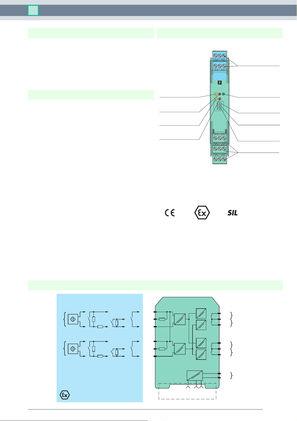
Assembly
Front view
LED yellow:
Relays channel Ι
LED red:
LB/SC channel Ι
LED yellow:
Relays channel ΙΙ
LED red:
LB/SC channel ΙΙ
2
1
5
4
KFD2-SR2-Ex2.2S
1
OUT CHK PWR
2
S1
S2
S3
III
7
8
10
11
13 15
14
Removable terminals
blue
3
6
LED green:
Power supply
Switch S1
(Mode of operation channel Ι)
Switch S2
(Mode of operation channel ΙΙ)
9
12
Switch S3
(LB/SC-monitoring)
Removable terminals
green
Connection
2
KFD2-SR2-Ex2.2S
1+
I
10 kΩ
400 Ω ≤ R ≤ 2 kΩ
10 kΩ
2+
3-
4+
II
10 kΩ
400 Ω ≤ R ≤ 2 kΩ
10 kΩ
5+
6-
7
8
9
10
11
12
I
II
III
IV
14+
24 V DC
15-
Zone 0, 1, 2
Release date 2010-02-02 18:14 Date of issue 2010-03-19 181284_ENG.xml
Subject to reasonable modifications due to technical advances. Copyright Pepperl+Fuchs, Printed in Germany
Div. 1, 2
Power Rail
24 V DCERR
Zone 2
Div. 2
Pepperl+Fuchs Group • Tel.: Germany +49-621-776-0 • USA +1-330-4253555 • Singapore +65-67-799091 • Internet www.pepperl-fuchs.com
1
Page 2

Technical data KFD2-SR2-Ex2.2S
General specifications
Signal type Digital input
Supply
Connection Power Rail or terminals 14+, 15Rated voltage 20 ... 30 V DC
Ripple ≤ 10 %
Rated current ≤ 50 mA
Power loss 1 W
Power consumption < 1.3 W
Input
Connection terminals 1+, 2+, 3-; 4+, 5+, 6Rated values acc. to EN 60947-5-6 (NAMUR)
Open circuit voltage/short-circuit current approx. 8 V DC / approx. 8 mA
Switching point/switching hysteresis 1.2 ... 2.1 mA / approx. 0.2 mA
Line fault detection breakage I ≤ 0.1 mA , short-circuit I > 6 mA
Pulse/Pause ratio ≥ 20 ms / ≥ 20 ms
Output
Connection output I: terminals 7, 8 ; output II: terminals 8, 9 ; output III: terminals 10, 11 ; output IV: terminals 11, 12
Collective error message Power Rail
Output I, II, III, IV channel 1, 2; relay
Contact loading 50 V AC/1 A/cos φ > 0.7; 40 V DC/1 A resistive load
Minimum switch current 1 mA / 24 V DC
Energized/De-energized delay approx. 20 ms / approx. 20 ms
Mechanical life 108 switching cycles
Transfer characteristics
Switching frequency ≤ 10 Hz
Electrical isolation
Output/power supply Basic insulation according to IEC 61140, rated insulation voltage 50 V
Output/Output Basic insulation according to IEC 61140, rated insulation voltage 50 V
Directive conformity
Electromagnetic compatibility
Directive 2004/108/EC EN 61326-1:2006
Low voltage
Directive 2006/95/EC EN 50178:1997
Conformity
Electromagnetic compatibility NE 21
Protection degree IEC 60529
Protection against electric shock IEC 61140
Ambient conditions
Ambient temperature -20 ... 60 °C (-4 ... 140 °F)
Mechanical specifications
Protection degree IP20
Mass approx. 150 g
Dimensions 20 x 119 x 115 mm (0.8 x 4.7 x 4.5 in) , housing type B2
Data for application in connection
with Ex-areas
EC-Type Examination Certificate PTB 00 ATEX 2083 , for additional certificates see www.pepperl-fuchs.com
Group, category, type of protection ¬ II (1)GD [EEx ia] IIC [circuit(s) in zone 0/1/2]
Input EEx ia IIC
Voltage Uo 10.5 V
Current Io 13 mA
Power Po 34 mW (linear characteristic)
Supply
Maximum safe voltage U
m
253 V AC / 125 V DC (Attention! Um is no rated voltage.)
Output
Contact loading 50 V AC/1 A/cos φ > 0.7; 40 V DC/1 A resistive load
Maximum safe voltage U
m
253 V AC (Attention! The rated voltage can be lower.)
Statement of conformity TÜV 99 ATEX 1493 X , observe statement of conformity
Group, category, type of protection,
¬ II 3G Ex nA nC IIC T4
temperature classification
Electrical isolation
Input/input not available
Input/Output safe galvanic isolation acc. to EN 50020, voltage peak value 375 V
Input/power supply safe galvanic isolation acc. to EN 50020, voltage peak value 375 V
Directive conformity
Release date 2010-02-02 18:14 Date of issue 2010-03-19 181284_ENG.xml
Subject to reasonable modifications due to technical advances. Copyright Pepperl+Fuchs, Printed in Germany
Pepperl+Fuchs Group • Tel.: Germany +49-621-776-0 • USA +1-330-4253555 • Singapore +65-67-799091 • Internet www.pepperl-fuchs.com
eff
eff
2
Page 3

Technical data KFD2-SR2-Ex2.2S
Directive 94/9/EC EN 50014, EN 50020 , EN 60079-0:2006, EN 60079-15:2005
International approvals
FM approval
Control drawing 116-0035
CSA approval
Control drawing 116-0047
General information
Supplementary information EC-Type Examination Certificate, Statement of Conformity, Declaration of Conformity, Attestation of
Conformity and instructions have to be observed where applicable. For information see www.pepperlfuchs.com.
Release date 2010-02-02 18:14 Date of issue 2010-03-19 181284_ENG.xml
Subject to reasonable modifications due to technical advances. Copyright Pepperl+Fuchs, Printed in Germany
Pepperl+Fuchs Group • Tel.: Germany +49-621-776-0 • USA +1-330-4253555 • Singapore +65-67-799091 • Internet www.pepperl-fuchs.com
3
Page 4

Technical data KFD2-SR2-Ex2.2S
Configuration
Switch position
S Function Position
123
456
1
PWRCHKOUT
2
123
S1
S2
S3
789
10 11 12
13 14 15
S1
S3
123
IIS2I
1 Mode of operation
Channel I (relay)
energized
2 Mode of operation
Channel II (relay)
energized
3 Line fault detection ON I
Operating status
Control circuit Input signal
Initiator high impedance/
contact opened
Initiator low impedance/
contact closed
Lead breakage,
lead short-circuit
with high input current I
with low input current II
with high input current I
with low input current II
OFF II
low input current
high input current
Line fault
Factory settings: switch 1, 2 and 3 in position I
Accessories
Power feed modules KFD2-EB2...
The power feed module is used to supply the devices with 24 V DC via the Power Rail. The fuse-protected power feed module
can supply up to 100 individual devices depending on the power consumption of the devices. A galvanically isolated mechanical
contact uses the Power Rail to transmit collective error messages.
Power Rail UPR-03
The Power Rail UPR-03 is a complete unit consisting of the electrical inset and an aluminium profile rail 35 mm x 15 mm. To
make electrical contact, the devices are simply engaged.
The Power Rail must not be fed via the device terminals of the individual devices!
Release date 2010-02-02 18:14 Date of issue 2010-03-19 181284_ENG.xml
Subject to reasonable modifications due to technical advances. Copyright Pepperl+Fuchs, Printed in Germany
Pepperl+Fuchs Group • Tel.: Germany +49-621-776-0 • USA +1-330-4253555 • Singapore +65-67-799091 • Internet www.pepperl-fuchs.com
4
 Loading...