

Page 1
Isolated switch amplifiers
KFD2-SR2-Ex1.W
Output: relay
Input I EEx ia IIC
24 V DC
• 1-channel
• Control circuit EEx ia IIC
• Reversible mode of operation
• 1 relay output with 1 changeover
contact
• EMC acc. to NAMUR NE 21
• LB/SC monitoring
• LB/SC collective error message via
Power Rail
• Usable up to SIL 2 acc. to IEC 61508
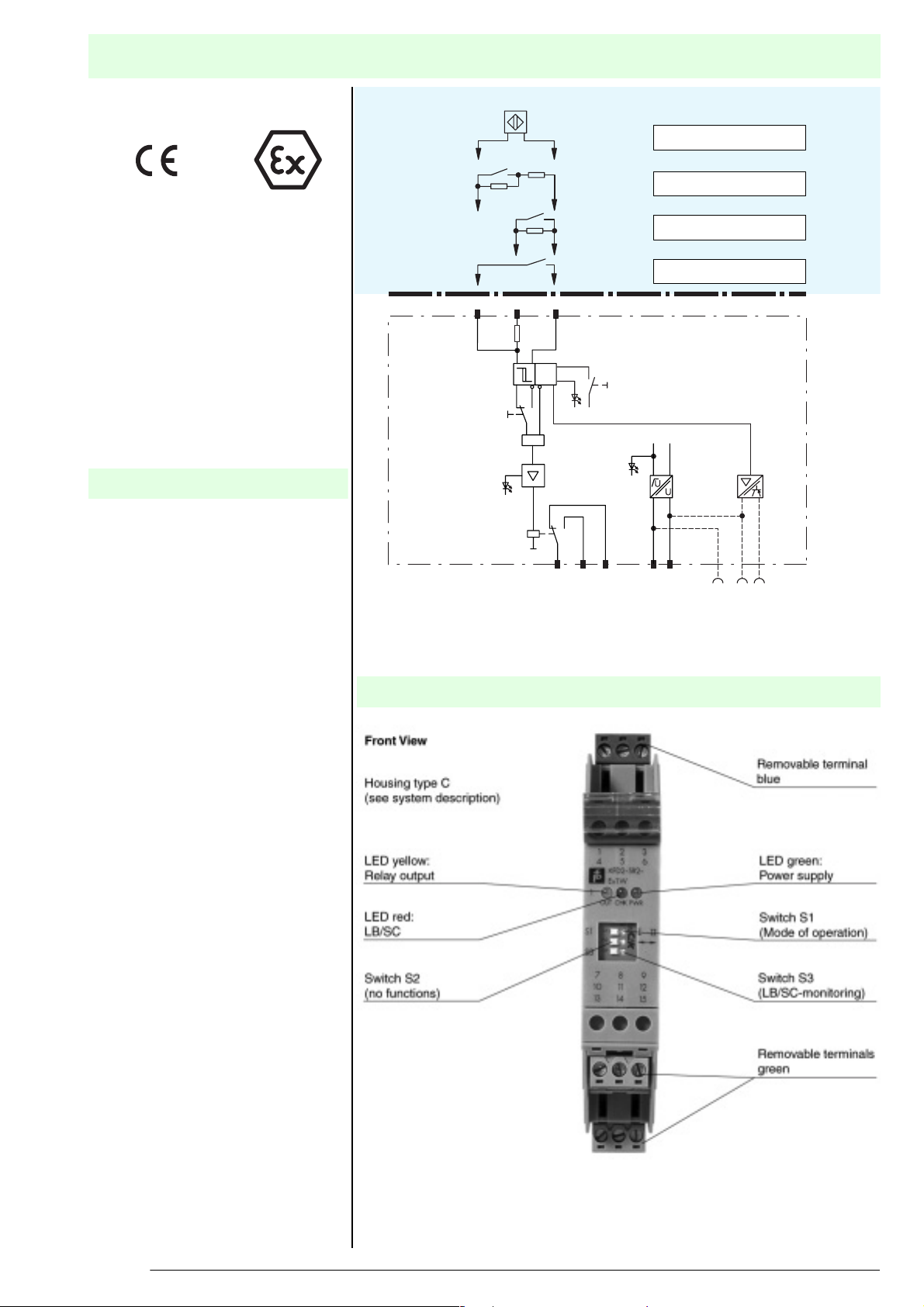
Function
The transformer isolated barrier
transfers digital signals from the
hazardous area. Sensors per
DIN EN 60947-5-6 (NAMUR) and
mechanical contacts may be used as
alarms. Control circuits are monitored
for lead breakage (LB) and short circuit
(SC). The external faults are indicated
according to NAMUR NE44 by a red
flashing LED. For type KFD2-SR2Ex1.W, an LB/SC collective error
message is in addition transferred
through the Power Rail to the power
feed module. The intrinsically safe input
is per DIN EN 50020 safely isolated
from the output and the power supply.
The relay output is in accordance with
IEC 61140 safely isolated from the
power supply.
1+ 3-
1+ 3-
without SC
without LB, SC
1+
Composition
10 kΩ
2+
S1
yellow
400 Ω ≤ R ≤ 2 kΩ
10 kΩ
3-2+
3-1+
3-
LB
SC
II
I
&
S3
red
green
789
Output Power
14 15
supply
Switch S3 in position I
Switch S3 in position I
Switch S3 in position I
Switch S3 in position II
+-
+
-
Power
Rail
only
KFD2-SR2-Ex1.W
Hazardous area
Safe area
LB/SC
collective
error message
103367_ENG.xml 2003-03-25
Subject to reasonable modifications due to technical advances. Copyright Pepperl+Fuchs, Printed in Germany
1
Pepperl+Fuchs Group • Tel.: Germany +49 621 776-0 • USA +1 330 4253555 • Singapore +65 67799091 • Internet http://www.pepperl-fuchs.com
Page 2

Technical Data
Supply
Connection Power Rail or terminals 14+, 15-
Rated voltage 20 ... 30 V DC
Ripple ≤ 10 %
Rated current 20 ... 23 mA
Input
Connection terminals 1+, 2+, 3-
Rated values acc. to IEC 60947-5-6 (NAMUR, DIN 19234), see system description for electrical data
Open circuit voltage/Short-circuit current approx. 8 V DC / approx. 8 mA
Switching point/Switching hysteresis 1,2 ... 2,1 mA / approx. 0,2 mA
Pulse / Pause ratio ≥ 20 ms / ≥ 20 ms
Lead monitoring breakage I ≤ 0,1 mA , short-circuit I > 6 mA
Output
Connection terminals 7, 8, 9
Output signal ; relay
Contact loading 253 V AC / 2 A / cos ϕ > 0.7; 126.5 V AC / 4 A / cos ϕ > 0.7; 40 V DC / 2 A resistive load
Energised/De-energised delay approx. 20 ms / approx. 20 ms
Mechanical life
Transfer characteristics
Switching frequency < 10 Hz
Electrical isolation
Output/Power supply reinforced insulation according to IEC 61140, rated insulation voltage 300 V
Standard conformity
Climatic conditions acc. to DIN IEC 721
Directive conformity
Electromagnetic compatibility standards
Directive 89/336/EG EN 61326, EN 50081-2, NE 21
Ambient conditions
Ambient temperature -20 ... 60 °C (253 ... 333 K)
Mechanical specifications
Protection degree IP20
Mass approx. 150 g
Data for application in conjunction
with hazardous areas
EC-Type Examination Certificate PTB 00 ATEX 2080 , for additional certificates see www.pepperl-fuchs.com
Group, category, type of protection ¬ II (1) G D [EEx ia] IIC [circuit(s) in zone 0/1/2]
Input EEx ia IIC
Voltage U0 10,5 V
Current I0 13 mA
Power P0 34 mW (linear characteristic)
Type of protection [EEx ia and EEx ib]
Explosion group IIA IIB IIC
External capacitance 75 µF 16,8 µF 2,41 µF
External inductance 1 H 840 mH 210 mH
Statement of conformity TÜV 99 ATEX 1493 X , observe statement of conformity
Group, category, type of protection,
Temperature classification
Supply
Safety maximum voltage U
Output
Contact loading 253 V AC / 2 A / cos ϕ > 0.7; 126.5 V AC / 4 A / cos ϕ > 0.7; 40 V DC / 2 A resistive load (PTB 00 ATEX 2080)
Safety maximum voltage U
Electrical isolation
Input/Output safe electrical isolation acc. to EN 50020, voltage peak value 375 V
Input/Power supply safe electrical isolation acc. to EN 50020, voltage peak value 375 V
Directive conformity standards
Directive 94/9 EU EN 50014, EN 50020, EN 50021
Entity parameter
Certification number J.I.3002773
FM control drawing No. 116-0035
Suitable for installation in division 2 yes
Connection terminals 1, 3; 2, 3; 4, 6; 5, 6
Input I
Voltage VOC 12,9 V
Current It 19,8 mA
103367_ENG.xml 2003-03-25
Subject to reasonable modifications due to technical advances. Copyright Pepperl+Fuchs, Printed in Germany
m
m
107 switching cycles
¬ II 3 G EEx nAC IIC T4 [device in zone 2]
253 V AC / 125 V DC (Attention! Um is no rated voltage.)
50 V AC / 4 A / cos ϕ > 0.7; 40 V DC / 2 A resistive load (TÜV 99 ATEX 1493 X)
253 V AC (Attention! The rated voltage can be lower)
KFD2-SR2-Ex1.W
eff
Pepperl+Fuchs Group • Tel.: Germany +49 621 776-0 • USA +1 330 4253555 • Singapore +65 67799091 • Internet http://www.pepperl-fuchs.com
2
Page 3

KFD2-SR2-Ex1.W
Explosion group A&B C&E D, F&G
Max. external capacitance C
Max. external inductance La 84,8 mH 254,4 mH 678,4 mH
Safety parameter
UL control drawing E 106378
CSA control drawing LR 36087-19
Control drawing No. 116-0047
Connection terminals 1, 3; 2, 3; 4, 6; 5, 6
Input I
Safety parameter 12,6 V / 650 Ohm
Voltage VOC 12,9 V
Current ISC 19,8 mA
Explosion group A&B C&E D, F&G
Max. external capacitance C
Max. external inductance La 84,88 mH 298,7 mH 744,4 mH
1,273 µF 3,82 µF 10,18 µF
a
1,273 µF 3,82 µF 10,18 µF
a
Supplementary information
EC-Type Examination Certificate, Statement of Conformity, Declaration of Conformity and instructions have to be observed.
This information can be found under www.pepperl-fuchs.com
Accessories
PR-03 Power Rail
UPR-03 Power Rail
KFD2-EB2 power feed module
The KFD2-EB2 power feed module and the PR-03 or the UPR-03 Power Rail are used to supply the devices with 24 VDC and
at the same time to evaluate combined fault indications.
Each power feed module monitors and provides protection for groups of as many as 100 individual devices. The PR-03 Power
Rail is an insert component for the DIN rail. The UPR-03 Power Rail is a complete unit consisting of an electrical insert and an
aluminium DIN rail measuring 35 mm x 15 mm x 2000 mm. The devices are simply snapped in place to make electrical
contact.
If a Power Rail is not being used, power can be supplied to the devices directly through the device terminals.
103367_ENG.xml 2003-03-25
Subject to reasonable modifications due to technical advances. Copyright Pepperl+Fuchs, Printed in Germany
3
Pepperl+Fuchs Group • Tel.: Germany +49 621 776-0 • USA +1 330 4253555 • Singapore +65 67799091 • Internet http://www.pepperl-fuchs.com
 Loading...