

Page 1

Model C-SOFT
User Configurable Version
USB and Parallel Key Versions
Radio Control Console
Includes P25 Control Options
Version 3.0x
August 2006
Page 2

2
Table of Contents
1
INTRODUCTION.............................................................................................................................................
2
COMPUTER SYSTEM REQU
3
SOFTWARE INSTALLATION.......................................................................................................................
3.1 PROGRAM I
3.2
D
RIVER INSTALLATION
3.3
I
NITIAL PROGRAM LAUNCH
3.4 CS
3.5
4
4.1
OFTRUNTIME.EXE DEFAULT LOAD FILE
I
NITIAL VOLUME CONTROL SETTINGS
COMMUNICATIONS SYSTE
W
HITE PAPER EXCERPT
4.1.1
4.1.2 VoI
4.1.3
4.1.4
4.1.5
4.1.6
4.1.7
4.1.8
4.2
N
ETWORK REQUIREMENTS
4.2.1
4.2.2
NSTALLATION
Tone Remote Control..............................................................................................
P Radio Control................................................................................................
IP Operation Overview ...........................................................................................
Ethernet as Physical Layer......................................................................................
TCP/IP and UDP/IP ..............................................................................................10
Multicast UDP/IP..................................................................................................10
Vega Port Centric Method.....................................................................................11
P25 and Initial Radio Standards............................................................................11
Bandwidth .............................................................................................................11
Multicast................................................................................................................11
IREMENTS
................................................................................................................................
...................................................................................................................................
.............................................................................................................................
M DESIGN
...................................................................................................................................
............................................................................................................................11
...................................................................................................
......................................................................................................
.............................................................................................................
....................................................................................................
4.2.3 IGMP.....................................................................................................................11
4.2.4
Network Performance ...........................................................................................11
6
6
7
7
7
8
8
8
9
9
9
.9
9
9
5
COMMUNICATIONS SCREE
5.1
O
VERVIEW
5.2
N
OTES ON WINDOW SIZES
5.3 IP P
5.3.1
5.3.2
..................................................................................................................................................... 12
ARAMETERS SETUP
Packet Delay..........................................................................................................13
Line Type ..............................................................................................................13
N DESIGN REFERENCE
, L
OCATIONS, AND
.................................................................................................................................13
SHUTDOWN
......................................................................... 12
,
AND SAVING THE CONSO
LE STATE
..................... 12
5.3.3 Line Number .........................................................................................................14
5.3.4
5.3.5
5.3.6
5.3.7
5.3.8
5.3.9
5.3.10
5.3.11
5.3.12
5.3.13
5.3.14
5.3.15
5.3.16
5.3.17
RX and TX Multica
st Addresses...........................................................................14
RX and TX Ports...................................................................................................14
TTL
-Time To Live................................................................................................14
TxMon Enable.......................................................................................................14
Talk Group ............................................................................................................14
NAC ...................................................................................................................... 14
Scanable Column...................................................................................................14
Autofill..................................................................................................................15
Echo Packets Enable .............................................................................................16
Freqs Button per Line............................................................................................16
Per Line Pair Mode ...............................................................................................17
RX Block Lines.....................................................................................................17
Backup IP Setup....................................................................................................17
Base Radio IP........................................................................................................17
Page 3

3
5.3.18
5.4
P
AGING ENCODER SETUP
5.4.1 Paging Option Checkboxes...................................................................................18
5.4.2
5.4.3
5.4.4
5.4.5
5.5
G
5.5.1
5.5.2
5.5.3
5.5.4
5.5.5
5.5.6 License Server.......................................................................................................25
5.5.7
5.5.8
5.5.9
5.5.10
5.5.11
5.5.12
5.5.13
5.5.14
5.5.15
5.5.16
5.5.17
5.5.18
5.5.19
5.5.20 Positional Recording Settings ...............................................................................26
5.6 P25 S
5.6.1
5.6.2
5.6.3
5.6.4
5.6.5 P25 Private ID Ca
5.7
U
5.8
C
5.9
I
NTERFACE ITEM MANIPULATION
5.9.1
5.9.2
5.9.3
5.9.4
5.9.5
5.9.6
5.9.7 Drop, Drag, and Copy...........................................................................................29
5.10
U
5.10.1 Button Function List..............................................................................................31
5.10.1.1
5.10.1.2
Setup JEM Boxes..................................................................................................17
..............................................................................................................................18
2 Tone 100 Setup: ................................................................................................
2 Tone 1000 Setup: ...............................................................................................21
DTMF Paging: ......................................................................................................23
Manual P
LOBAL SETUP
DTMF Setup..........................................................................................................24
Sup
Local Console IP Address / Ethernet Crossmute..................................................24
IP Interface............................................................................................................24
HB3 Serial Port .....................................................................................................24
Windows Controls................................................................................................
Bitmap Logo Setup ...............................................................................................25
Background Color................................................................................................
Audio Routing and Muting ...................................................................................25
Enable Sticky ANI ................................................................................................25
Kill Lines on Crosspatch (2.7) ..............................................................................25
Radio Ping Interval................................................................................................25
RX Block Delay....................................................................................................25
Tones/DTMF Sidetone Level (2.93).....................................................................26
Allow Freq Update Anytime (2.93) ......................................................................26
MIC AGC Enable and Settings.............................................................................26
Phone Ringer Multicast and Port ..........................................................................26
NEO Multicast and Port Numbers ........................................................................26
ETUP MENU
Console Unit ID ....................................................................................................27
Console RSI ..........................................................................................................27
KMF Reply NID....................................................................................................27
P25 Late Entry.......................................................................................................27
SER
ID L
IST
RYPTO KEY ENTRY
Edit Menu Options................................................................................................28
Delete Items (Cut)................................................................................................
Copy Items ............................................................................................................28
Paste Items.............................................................................................................29
Open Popup...........................................................................................................29
Properties...............................................................................................................29
SER INTERFACE ELEMENT REFERENCE
PTT-Main..........................................................................................................31
PTT-Per Line.....................................................................................................31
aging Entry.............................................................................................23
.............................................................................................................................................. 24
ervisor Timeout...............................................................................................24
.......................................................................................................................................... 27
ll Listen ....................................................................................27
................................................................................................................................................ 27
(P25 O
NLY
)
.................................................................................................................28
..................................................................................................................28
..................................................................................................30
.18
.25
.25
.28
Page 4

4
5.10.1.3
5.10.1.4
5.10.1.5
5.10.1.6
5.10.1.7
5.10.1.8 A
5.10.1.9
5.10.1.10
5.10.1.11
5.10.1.12
5.10.1.13
5.10.1.14
5.10.1.15
5.10.1.16
5.10.1.17
5.10.1.18
5.10.1.19
5.10.1.20
5.10.1.21
5.10.1.22
5.10.1.23
5.10.1.24
5.10.1.25
5.10.1.26
5.10.1.27
5.10.1.28
5.10.1.29
5.10.1.30
5.10.1.31
5.10.1.32
5.10.1.33
5.10.1.34
5.10.1.35
5.10.1.36
5.10.1.37
5.10.1.38 Phone-
5.10.1.39 Phone-Hold .......................................................................................................40
5.10.1.40 Phone-
5.10.1.41 Phone-
5.10.1.42
5.10.2
5.10.2.1
5.10.2.2
5.10.2.3
5.10.3
5.10.3.1
PTT-Talkback....................................................................................................31
Mute Main.........................................................................................................31
Mute
Per Line....................................................................................................31
Mute Group.......................................................................................................32
Select.................................................................................................................32
lert...................................................................................................................33
Page...................................................................................................................33
Page Stack.........................................................................................................34
Page Send..........................................................................................................34
Frequency Change.............................................................................................34
Frequency Variable...........................................................................................34
Group Select......................................................................................................34
Group Programmed........................................................................................... 34
TX All ...............................................................................................................35
RX All...............................................................................................................35
DTMF Digit ......................................................................................................35
Monitor..............................................................................................................35
Intercom ............................................................................................................35
Intercom-Instant................................................................................................35
Crosspatch.........................................................................................................35
Crosspatch Clear ...............................................................................................36
Crosspatch Block ..............................................................................................36
Crosspatch Programmed ...................................................................................36
Supervisor .........................................................................................................37
Page
Instant Recall.....................................................................................................38
P25-Select..........................................................................................................38
P25-Per Line PTT..............................................................................................38
P25-Encryption ................................................................................................
P25
Emergency Cancel.............................................................................................38
Emergency Acknowledge .................................................................................39
Input Indication................................................................................................
Relay Control
Marker Tone......................................................................................................39
Backup Line ......................................................................................................40
Volume Control Objects .......................................................................................40
Volume-Per Line...............................................................................................41
Volume-Master Select.......................................................................................41
Volume-Master Unselect ..................................................................................41
Popup Windows ....................................................................................................41
Web Pages within Popups.................................................................................41
Manual Entry (2.7) ................................................................................37
-User ID Call...............................................................................................38
Button ........................................................................................39
On/Offhook............................................................................................39
Flashhook...............................................................................................40
Autodial ................................................................................................
.38
.39
.40
Page 5

5
5.10.3.2
5.10.3.2.1
5.10.4
6
BASIC SCREEN DESIGN
6.1
F
IRST STEP SETUP BASIC
6.2
S
ECOND STEP MONITOR
6.3
S
TEP THREE CREATE FIRST COLUMN OF CONTROLS
6.4
S
TEP FOUR CREATE OTHER FIVE CONTROL COLUMNS
6.5 S
6.6
APPENDIX A. TROUBLES
S
7
TEP FIVE OTHER STANDARD CONTROLS
S
TEP
OCKET WARNING MESSAGE
WARRANTY, SERVICE, R
Popup Call History............................................................................................42
Call History IRR Playback........................................................................42
Adding Descriptive Text.......................................................................................43
6
T
ESTING THE DESIGN
TUTORIAL
IP P
ARAMETERS
, PTT
-M
......................................................................................................................49
HOOTING
.................................................................................................................................. 51
EPAIR, AND COMMENTS
.......................................................................................................44
.................................................................................................44
AIN, AND INTERCOM
..................................................................................................48
.................................................................................................................51
............................................................................... 45
.................................................................................. 46
.............................................................................. 47
........................................................................... 52
Page 6

1 Introduction
The original version of the C-Soft console from Telex-Vega provided a user interface much like the user interfaces
standard and Vega s standalone desktop console. With the release of Version 3.0, the radio technician is now able
to completely define the look and operational characteri
of Vega VoIP products, C-Soft represents another method for controlling a radio network utilizing standard
computing equipment.
The C-Soft software console is protected from copying by the use of a security dongle attached to either the parallel
printer port, or to a USB port. Software updates are freely available within the same version family by simply
downloading them from our website at
www.vega-
stics of the radio operator s interface. With an infrastructure
signaling.com.
2 Computer System Requirements
6
Operating System:
Sound System:
Network Connection:
Processor Speed:
Memory:
Full Duplex windows compatible sound system. Sound Blaster or HW
Celeron 500 or greater especially if controlling P25 radios or large numbers of
Windows 2000 or XP required.
compatible recommended.
10 Mbps or 100Mbps TCP/IP connecti
radios.
Minimum of 256Mbytes recommended
on. Constant IP address preferred.
Page 7
7
3 Software Installation
There are several steps to installing the C-Soft p
onto the computer and setup shortcuts to them.
3.1 Program Installation
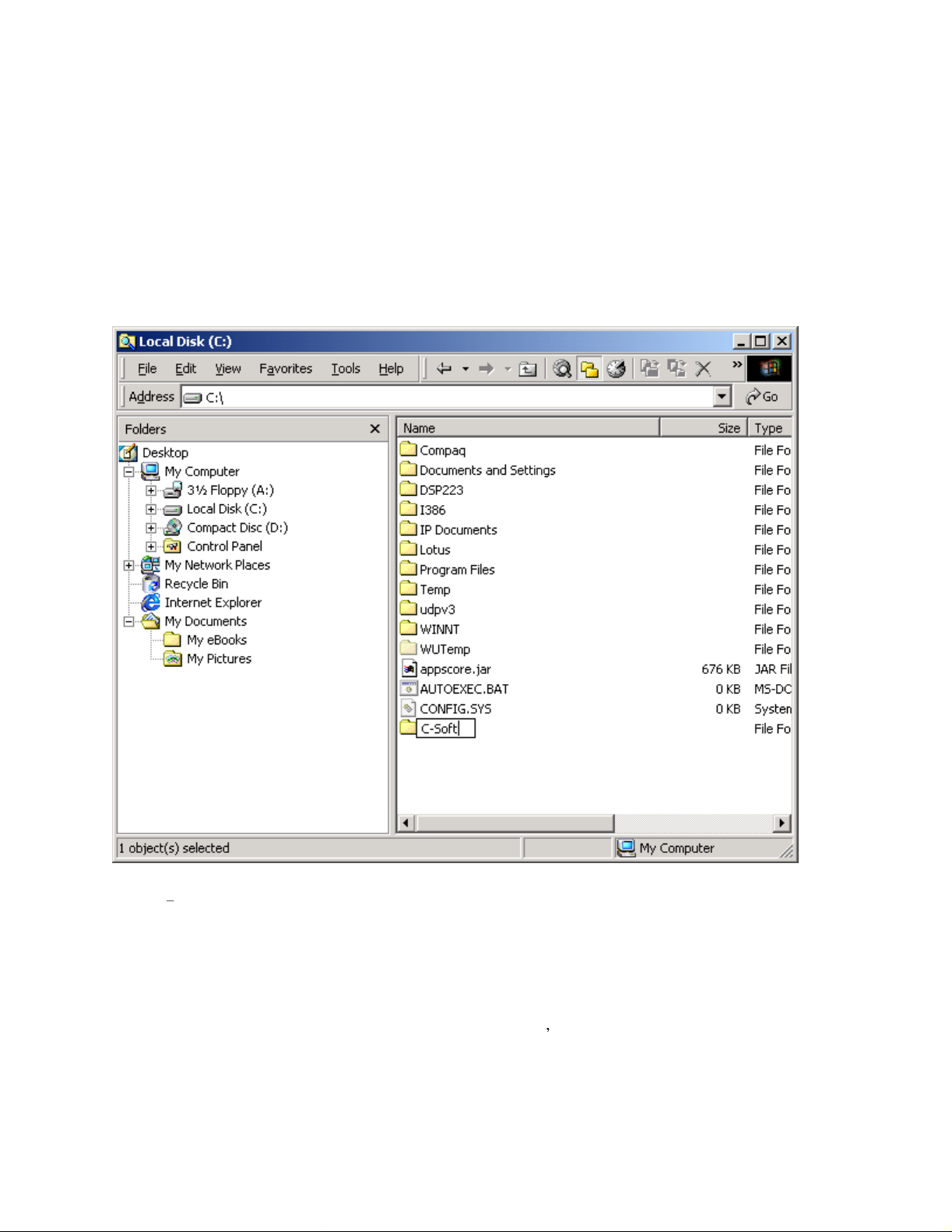
Step 1:
Open Windows Explorer and create a new subdirectory under the root directory called C-Soft. This can be
accompli
right pane, right click on an open spot and select New->Folder. The folder will appear and allow the user to enter a
name for the new folder. Use C-
shed by selecting a local hard disk drive (typically drive C:) in the left pane of Windows explorer. In the
Soft. See
ackage on a computer. The first is to copy the manual and program
Figure 1 for creation of the directory.
Figure 1 Adding a Directory for C-Soft
Step 2:
Copy the files CSoftRuntime.exe, CSoftDesigner.exe and C-Soft Manual 25.pdf from the included CD in
the newly created directory. Also copy C6200F_Default.veg into the new directory.
Step 3:
Create a shortcut on the desktop to open the CSoftRuntime.exe, CsoftDesigner.exe, and the Adobe .PDF
formatted document file. Telex-Vega suggests that the user
A copy of the Adobe Acrobat reader is included on the CD if it doesn t already exist on the users computer.
3.2 Driver Installation
Before the CSoftRuntime.exe file can be executed from the desktop Icon created in Section 3.1, a driver to allow the
to
print out a copy of the manual for reference purposes.
Page 8
8
program to access the security Dongle must be loaded.
installation of the driver.
setup wizard as it executes. A standard installation is the normal install and only a qualified IT professional should
attempt to use the manual install. The user will have to restart their computer after the installation of the Dongle
dri
ver is completed. Additional information on the driver installation can be found at
http://
www.rainbow.com
be installed. This al
the need for a licensed copy of the software. The output of the designer software is a file that is loaded by the
runtime program when it is started.
3.3 Initial P
After the successful installation of the program files, documentation, and dongle drivers, check the installation be
executing CSoftRuntime and CSoftDesigner. Each should load and run. A predefined screen will be executed by
the runtime sof
tware.
Execute file SPNComboInst1.0.5.exe included on the CD. Follow the dir
/support/eu_support.htm. The CSoftDesigner.exe program does not require the dongle to
lows the person responsible for the dispatcher s console interfaces to do screen design without
rogram Launch
3.4 CSoftruntime.exe Default Load File
By default the C6200F_Default.veg file is searched for in the same directory as the CSoftruntime.exe program. If
the file does not exist in the directory, no screen design is loaded and the console does not functi
recommended that the screen designer save designs under descriptive names and only save out the default load
filename when a design is ready to test.
Starting in version 2.52 the CSoftruntime.exe file will recognize a command line filename to lo
default name of C6200F_Default.veg. A short cut can be created to run a different screen design from the desktop
or the file type of .veg can be associated with CSofttunrime.exe so that the .veg files can be double-clicked from
anywhere
and cause the design to execute.
Make certain that no USB dongle is connected during the
ections of the
on. It is
ad instead of the
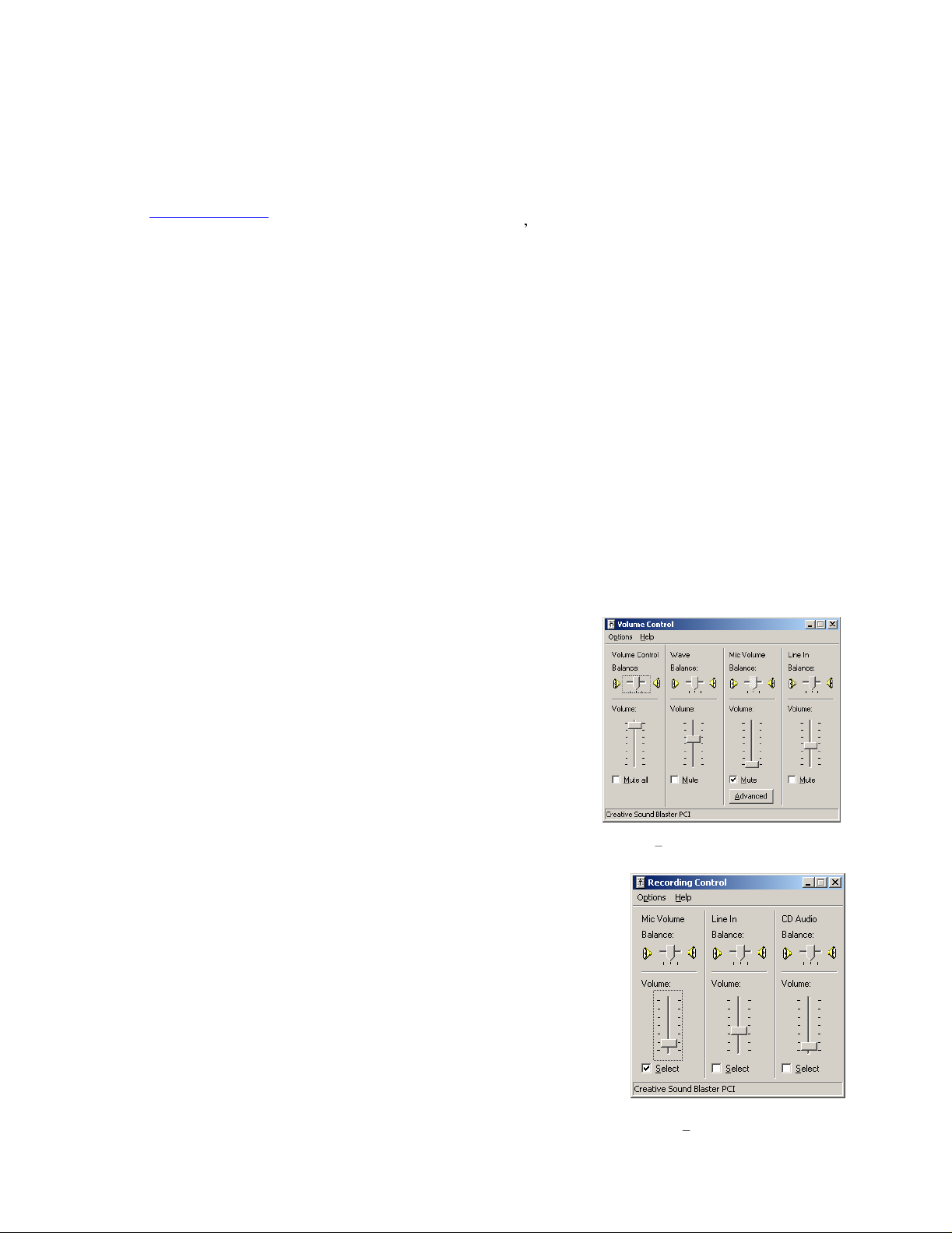
3.5 Initial Volume Control Settings
The volume control, normally resident in the tray, is used to control audio
output and input. The settings of these controls is crucial to the operation of
the software console. There are
volumes, and the other is the recording volumes. The playback volumes are
brought up by double clicking on the speaker in the system tray. Generally
the main and wave volumes are set to max as C-Soft will be used
the actual speaker levels. The other important playback setting is to mute
the microphone. Not muting the microphone will cause the microphone
audio to feedback from the speakers. The settings for playback should look
like
Figure
2.
The recording settings are accessed by going to the options menu, selecting
properties, changing the radio control to recording, and then pressing OK.
The microphone input is u
used with the microphone input. The microphone should be the Selected input
and the volume settings should be around the second tick. Figure 3 shows the
general playback settings.
two sets of settings, one is the playback
sed by C-Soft. The HB-3 alignment procedure is
to control
Figure 2 Playback volume settings
F
igure 3 Record volume settings
Page 9

4 Communications System Design
Setup of the C-Soft console involves understanding your radio network and how the various radios and console are
setup within it. It is very important that a complete roadmap of the locations of the radios and consoles be
determined before configuration begins. This includes the multicast address involved as well as the port number for
each channels TX and RX communications. It is also necessary to know the base IP addresses assigned to each
console or radio on the network for administration purposes. An excerpt from the Vega IP White paper is included
here to help the user understand how the network portion of the system works.
9
4.1 White Paper Excerpt
4.1.1
Telex Vega sells a full line of tone control consoles and radio adaptors. This technology requires an analog
connection between each console and each radio. Each console that needs to control an individual radio is wired in
parallel to allow multiple op
console positions and multiple radio channels, an entire rack might be devoted to bridging audio to all interested
parties. In addition, due to loading of multiple consoles on a particular circuit, additional bridging hardware might
be required, increasing wiring and tuning of the system for acceptable performance. The Ethernet based IP network
solves many of these issues and provides for a number of other services t
4.1.2
Radio over IP, being a subset of Voice over IP will be referred to as VoIP generically throughout this document.
VoIP is a method for breaking analog audio up into packets that can be transferred over a computer data network.
Because of the packetized nature of Ethernet, the audio is generally broken up into 10-40ms chunks of audio,
compressed, and placed onto the Ethernet. The nodes of the network are then free to utilize or ignore any
combination of packets. If a particular audio stream is of interest, the stream of audio packets are captured,
uncompressed, converted back to analog, and played on available speakers.
Given the popularity of the Ethernet based network, many companies and agencies already h
or Local Area Network (LAN). Beyond that, a large number of companies exist to provide Wide Area Network
(WAN) connections between sites with significant distances between them. The WAN connections can be used to
connect offices across the street from one another, around the world, or anywhere in between. Possibly the best
thing about these connections is that they may already exist. In many cases WAN links are less expensive than a
comparable leased analog line, and they can car
The most compelling reason to consider basing the next radio control system upgrade on VoIP technology is the
simplification in wiring requirements. Instead of needing to bring a pair or more of wires, per channel, to each
console, only a single connection to the Ethernet is required. Since the Ethernet can easily handle dozens of
simultaneous connections it becomes the only pipeline required for all communications requirements.
Tone Remote Control
erator positions to monitor and control the same radio. For a large system with multiple
VoIP Radio Control
hat were not possible before.
ave an existing network
ry more conversations simultaneously.
4.1.3
The network optio
will sell many of the components for both a wired or wireless network solution. For more advanced network
applications, an in house or external network hardware source may be required. These sources of information will
be able to help with the design of the network as well as provide sources for advanced networking equipment such
as routers and hubs from Cisco and other network vendors. This section is an ove
on the top of the Ethernet network.
4.1.4
Ethernet is itself a network. It has a low level method for transferring data from one location to another. Source and
destinations are based on the MAC address which is embedded in the Ethernet interface. The MAC address is
unique for all devices in the world and cannot be changed. The IEEE controls the allocation of the MAC addresses.
The definition for Ethernet includes requirements for interoperation at speeds of 10 and 100 Mbps. Higher speeds
are available but generally have not filtered down into end user equipment. It is upon this base that higher level
protocols such as IP are based.
IP Operation Overview
ns today have essentially converged on Ethernet. A local Best Buy, Office Depot, or Radio Shack
Ethernet as Physical Layer
rview of the protocol that operates
Page 10

10
4.1.5
TCP/IP is the best-known protocol for use in computer communications. It is the basis for communications on the
Internet and World Wide Web. It is a guaranteed method of transferring data between two computers. Being
guaranteed means that for every packet of information transferred from one computer to another an
acknowledgement packet is returned. Additional handshaking is utilized from the outset of the data communications
to guarantee both ends of the connection. Because of this guaranteed communications and its implementation
utilizing handshaking (no other method is available), TCP/IP adds a great deal of overhead to data communications
that is not desirable for audio traffic over a network. This is where UDP/IP finds is acceptance.
UDP/IP has existed just a long as TCP/IP as an unreliable method of data communications. The term unreliable
should not be thought of as a problem for audio communications over a network connection. UDP allows for a
computer to send a packet of data to another computer without the handshaking sequence required within TCP/IP.
Because of this, the computer that sends the packet has no confirmation that the packet arrived at its destination.
While the loss of packets can be a problem, it generally is accounted for when the UDP application is developed. In
the case of VoIP, the loss of a packet which only contains 10-40ms of audio is not a problem as the human ear
generally will ignore the loss of that small chunk of audio. In addition, programmers play tricks to make this loss of
information difficult to detect to the human ear. The largest single factor in the lost of UDP/IP packets is network
design and loading. As long as a network is well designed with capacity for all of its chartered requirements, packet
loss will not be an issue. Because of its lower ove
for VoIP development.
4.1.6
Multicast is an extension to UDP/IP. It enabled one computer to broadcast data packets that has multiple recipients.
This is an ideal model for radio communications when multiple people need to monitor the audio. A single VoIP
connected radio is setup to broadcast multicast VoIP packets when receiving audio. Since the multicast packets can
be received by any interested party, all consoles that are
playback. In addition to simplifying monitoring of audio traffic by multiple listeners, multicast also greatly cuts the
bandwidth requirement on the network. Instead of having to regenerate the received audio into a UDP/IP data
stream to each individual monitor, which would use the bandwidth times the number of monitoring consoles, a
single data stream is generated and monitored by all.
TCP/IP and UDP/IP
Multicast UDP/IP
rhead and its ability to Multicast, UDP/IP is the protocol of choice
monitoring the audio can receive and decode the packets for
Implementation of Multicast protocol requires a few things for seamless use on a network. First the clients must all
support the protocol. This is accepted as given since all Vega products utilize multicast for audio communications.
The next issue to consider is if the network infrastructure supports multicast.
Multicast packets are defined to be all packets with a destination address of between 224.0.0.0 and 239.255.255.255.
Some are commonly used for broadcast audio and are not necessarily available. When a computer opens a UDP/IP
port within this address range, it will also join the group. By joining the group a packet is sent out to all addresses
saying that it is interested in seeing the traffic on this particular multicast address. Routers that receive this
broadcast message to join a particular multicast address will then pass packets through because the router is now
aware that a listener is interested in this traffic. The routers utilized in the network must support this. The protocol
used to alert routers to parties who are interested in certain multicast address traffic is IGMP or Internet Group
Management Protocol. The Vega products support IGMPv1 as defined in RFC 1112.
In addition to the joining of multicast broadcast groups, clients on the network can also specify a packet time to live.
The time to live (TTL) is the number of routers that the packet will go through before being stopped. As an
example, the time to live for a particular broadcasting node on the network is set to 3. This means that when a
packet is transmitted, it will arrive at the first router in the network. This router will examine the TTL value in the
packet and determine if it should pass it through since it is not zero. When it passes the packet, the router will
decrement the TTL value by one to a value of 2. The next router encountered by packet will do the same reducing
the value of TTL to 1. The next router does the same and the TTL is now 0. The next router the packet reaches will
examine the TTL value, see it is zero, and the packet will not be retransmitted. Se
for packets to get from one host to another on a large network, but will also add additional bandwidth requirements
due to the larger number of packets being transferred.
tting a large TTL value may allow
Page 11

11
4.1.7
As mentioned earlier, Telex Vega utilizes Multicast for all audio communications. In addition, typically only one
Multicast is used for all traffic. In addition to a valid Multicast address, a port number is required. The port is an
additional two bytes of information ranging between 1025 and 65535 that further specifies how the data traffic
should be handled. Assume for a moment that the base multicast address chosen is 225.8.11.81. Port 1054 is used
to distinguish channel 1's RX traffic. Port 1072 is used to specify channel
for RX and 1073 for TX traffic. By making each channel s TX and RX ports different and unique, full duplex audio
can be supported and many channels of traffic can be supported using only one multicast address. It is also through
this method that a single console can pick and choose the particular radio resources available on the network without
concern for what the console right next to it is utilizing.
4.1.8
TIA is the organization with
participate in this standards organization. The interface of choice for connecting infrastructure radios has become
Ethernet. This is the first standards body to address Radio control over IP. The standard is evolving and as of the
writing of the manual appears to be the only widely accepted standard for IP based radio control.
4.2 Network Requirements
4.2.1
Each VoIP channel requires 50kbit of bandwidth when active. A
50kbit of bandwidth during the transmission. When the transmission ends, the bandwidth will no longer be
required. If the conversation is a full duplex conversation, audio in each direction, then 100kbit of bandwidth with
bill required. 50kbit for each direction. Some radio systems will give go-ahead beeps when it is clear to talk, if the
dispatcher is going to hear them, it must be a full duplex conversation. The full duplex bandwidth may only be
re
of the transmission. When utilizing a PIB223 or C-6200 for a telephone connection, a full 100kbit is required since
it is a full time full
Vega Port Centric Method
1's TX traffic. Channel 2 might use 1055
P25 and Initial Radio Standards
in which the P25 radio standards have been developed. Most major radio manufacturers
Bandwidth
quired for the first few seconds of the conversation due to the brief nature of the go-ahead beeps at the beginning
duplex conversation.
transmission from a console to a radio will require
4.2.2
In general, the Telex-Vega system requires multicast to function. The network must be able to create a static
nailed-up multicast address. The multicast must be accessible at all times. It is very common for networks to
enable multicast for a period of time after an IGMP join message is sent out, and then prune off branches after a
period of time. Because of the nature of two-way radio and its intermittent usage patterns, this can create a
significant problem where the system appears to work flawlessly for a period of time and then no longer works. In
the Cisco world, ip pim dense-mode is generally recommended, sparseimplemented effectively. It is also generally a good idea to explicitly join the multicast group with a ip igmp staticjoin X.X.X.X command.
4.2.3
IGMP can be used to control where multicast is allowed to propagate to. This should generally be limited to subnets
utilizing C-Soft as the dispatch console, and only when used on an intermittent basis. That is, when C-Soft is used
for a while and then shut down. If a console is expected to be operational at all times on a subnet, then that subnet
should have multicast nailed up and active at all times.
4.2.4
The
delay added by the network. Delay does not cause issues, but variable delay (jitter) does. Jitter in a network cannot
exceed the maximum packet buffer of the individual products buffers. See each product manual for this
specification. As an example, the IP-223 can handle about 600ms of network jitter. For good audio quality, no
more than 5% of all packets transmitted should be lost. This is an absolute maximum, exceeding this value will
cause poor audio quality and system performance and in general practice packet loss should be much less than 1%.
Multicast
IGMP
Network Performance
network should perform well under all loading conditions. The default delay of the audio is 120ms, plus any
dense
-mode can also generally be
Page 12

12
5 Communications Screen Design Reference
5.1 Overview
The program, CSoftDesigner, is used for the creati
sliders, text, and popup windows are dynamically placed onto the screen. These elements are then configured to
operate on particular lines. The user of the design software can place the elem
include or omit functions based on the requirements of the system and the end operator of the console.
The first step in the process of creating a user interface is to define its interactions with your IP network. This
includes knowing the RX and TX port of each radio, the multicast group(s) utilized, the number of radios to control
and the frequencies that they might be using.
on of the dispatcher screens. Various combinations of buttons,
ents in any location desired and can
5.2 Notes on Window Sizes, Locations, and Shutdown, and saving
the console state
By default, desi
system, it may not be acceptable if only a small window is to be presented for radio control on a single monitor
system, or if the dispatcher is to run the
be taken to ease the design and execution of the software in these special cases. A general procedure follows, some
experimentation may still be required.
1) When CSoftDesigner is ex
2) If the design is new, create the design. If an existing design is being edited, step 1 should be completed
gner and runtime expand to fill the entire screen. While this is fine in a single monitor dedicated
of the designer window to match that of the window that should be presented to the dispatcher for the end
design. By doing this, all of the buttons will scale to the d
executed with the design.
before loading the design to edit. For initial designs, it is recommended that th
maximize, and close buttons be left enabled.
screen design on a multi-monitor computer. Because of this some steps can
ecuted, it will expand to fill the entire screen. The first step is to change the size
esigned size when CSoftRuntime is later
e resize, minimize,
3) Once the design looks as it should on screen in the designer application, save the file into the location from
which CSoftRuntime will execute it.
4) When CSoftRuntime is executed it looks for a
is shutdown. It stores the size and position of the CSoftRuntime window when it is closed. The first time
the program is run in a new directory, the cposi.txt file will not exist. CSoftRunt
whole screen. Assuming that the controls to resize and position the window are still active, position the
CSoftRuntime window to the location where it should always run from. The buttons will not rescale to this
window and som
of the window is what is being created. Once the size and position is approximately correct, close the
CSoftRuntime program, the cposi.txt file will be updated.
In
addition to storing the position information of the window, starting in version 2.90, cposi.txt also stores
the console state at shutdown. It stores the selected channels, mute states, volumes, channel frequencies,
and the entries in the call log (without
is started up, it is likely that these line states won t match.
5) Run the CSoftRuntime program again. The window should return to its last location and size with the
buttons, sliders, VU
6) Variations on this process can be attempted to get desired results. Once a size and location is determined,
the cposi.txt file can be made read only by adjusting its properties. The user may still be able to resize
window, but each time CSoftRuntime is executed, it will return to its original location.
When C-Soft is shutdown, in addition to the size and location of the window being stored in cposi.txt, the
current console state is stored. This includes selecte
audio stored, only the entries).
e may be hidden from view by this process. This is not a problem as the size and position
Meter, and clock in correct locations.
file called cposi.txt. This file is written when CSoftRuntime
ime will expand to fill the
the IRR audio). If one console design is shut down and different one
the
d status, mute status, channel frequency, and the call list (no
Page 13

13
5.3 IP Parameters Setup
Figure 4 IP Parameters Setup Screen
The first option under the Edit menu is the Setup IP Multicast List opti
dialog box shown in
The dialog box contains some data. If no file has been loaded to edit and no changes have been ma
state has Line 1 as the only line enabled with only one Frequency enabled (F1). The designer should go through and
enabled all lines that this console position will have access to as well as the frequencies allowed for each line. Many
of
the dialog boxes associated with the setup of the user interface elements depend on this setup. If a line that is
later required is not enabled from this dialog box, it will not appear as an option for setup. The same is true for
frequencies associated w
would then allow or disallow their selection in subsequent operations. Each of the columns are defined in the
following sections.
5.3.1
This setting is used
before playback, the more the console software can do to compensate for lost and delayed packets. The greater this
value, the more delay is introduced before
into a delay of 120ms before playback. (Each packets is 20ms of audio.) The speed of the PC, its sound card type,
and the operating system it is running all affect the delay be
parameter.
5.3.2
Three types of lines are currently available for control. One of them is None, in other words, no line is enabled. The
second option in the drop down dialog box is for a line type of Vega. The Vega setting is used to be compatible
with Telex
option. This option is compatible with the EF Johnson 2600 Series repeater. The forth option is
option allows the console to access a telephone line from across the network. From this option, other options are
selectively enabled or disabled.
Packet Delay
Line Type
-Vega s Radio control over IP products such as the C-
Figure 4, and is generally the first step in creating a new screen design.
ith the line. The designer can return to this dialog box at any time to make changes which
to compensate for network delays, jitter, and lost packets. The more packets that are buffered
on. Selecting this option will open the
de, the default
playback of the audio begins. A typical initial value is 6. This translates
fore playback and is beyond the control of this
6200 or the IP-223. The third option is the P25
Phone. The Phone
Page 14

4
1
5.3.3 Line Number
The Line Number is the logical number of the line in the system. In most cas
dependent on the names given in the later fields, but a couple of items do refer to this logical number. No editing is
possible for this entry.
es, design of the console screen is
5.3.4
The RX and TX Multicast Addresses are used as
number must be between 224.0.0.2 and 239.255.255.255. All devices that are to interoperate on this channel must
have the same respective Multicast Address for RX and TX channels. Generally,
enabled equipment, one multicast address is used for all channels with the port number defining the TX and RX
channels.
Conversely, on some P25 types of equipment, it is common to use different Multicast addresses and sometimes
same address for each several different lines. In this case, differentiation between the two lines traffic is completed
by reviewing the NAC value.
5.3.5
These numbers must be unique, per channel, and be greater than 1024. As an example, co
Figure 4. The RX Port is 1054 and the TX Port is 1104. All consoles that wish to monitor receive audio for channel
1 must have their Base Multicast address set the same as well as the same RX Port number. The
audio. Any console on the network that wishes to transmit must set its port number to 1104 to cause the radio to
keyup.
For the EFJ P25 option, the port number should be set to 10110 at all times for both TX and RX Ports.
5.3.6
The Time to Live value represents the number of routers the multicast audio packets will go through before being
stopped. Network design will dictate this value. If audio is not reaching a particular node on the network,
increasing this value is one opt
5.3.7
The TX Monitor enable allows the user to monitor other TX traffic being sent from other console operators.
RX and TX Multicast Addresses
RX and TX Ports
TTL-Time To Live
TxMon Enable
ion that might be tried.
the broadcast address for all audio traffic. This dotted quad
when dealing with Vega VoIP
the
nsider Line 1 above in
same goes for TX
5.3.8
The Talk Group option is only available for entry when the line type is EFJ P25. This is the Talk Group value that
will be embedded into this lines transmission.
5.3.9
The NAC is the Network Access Code and is only available when the line type is EFJ P25. This will be the value of
the NAC that is sent when traffic is generated on this line. In addition, the NAC is used to route receive audio to a
unique channel based on the NAC value received from the repeater.
5.3.10
The Scanable column is used to allow a dispatcher to control the scan list of a particular radio. As of publication of
this manual, only the Kenwood x150 and x80 series support this functionality. If this box is checked, not only does
the scan button function, but the frequency buttons for this line can be right clicked and the channel be added or
deleted from the scan list. Se
Talk Group
NAC
Scanable Column
e the frequency change button description for more information on this feature.
Page 15
15
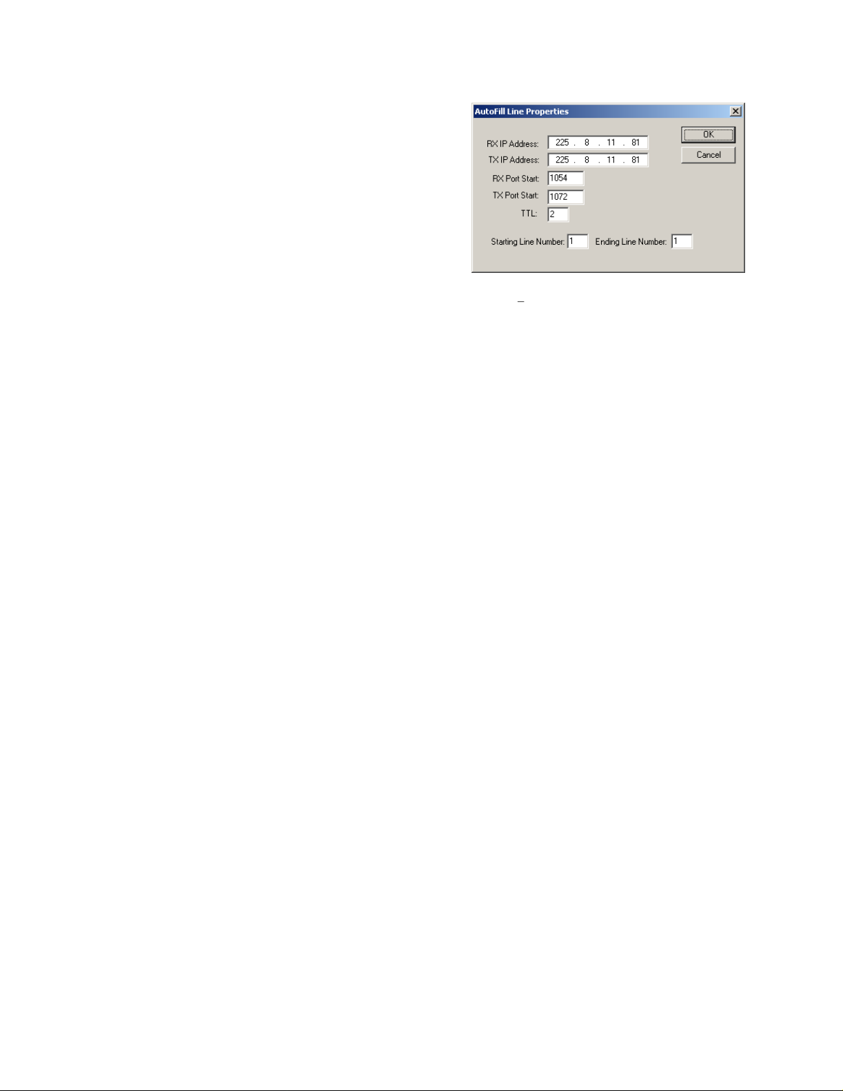
5.3.11
The Autofill button allows the console designer to quickly fill
blocks of lines with information. This button can be used to
eliminate repetitious data entry by hand. The function will
automatically increment the RX and TX port numbers as it fills
in the lines selected.
Autofill.
Autofill
Figure
5 shows the dialog box used for
Figure 5 Autofill dialog box
Page 16
16
10.7.100.200:1074
Echo1: RX 10.7.100.200:1054 TX 10.7.100.200:1072
Echo2: RX 10.6.100.200:1055 TX 10.6.100.200:1073
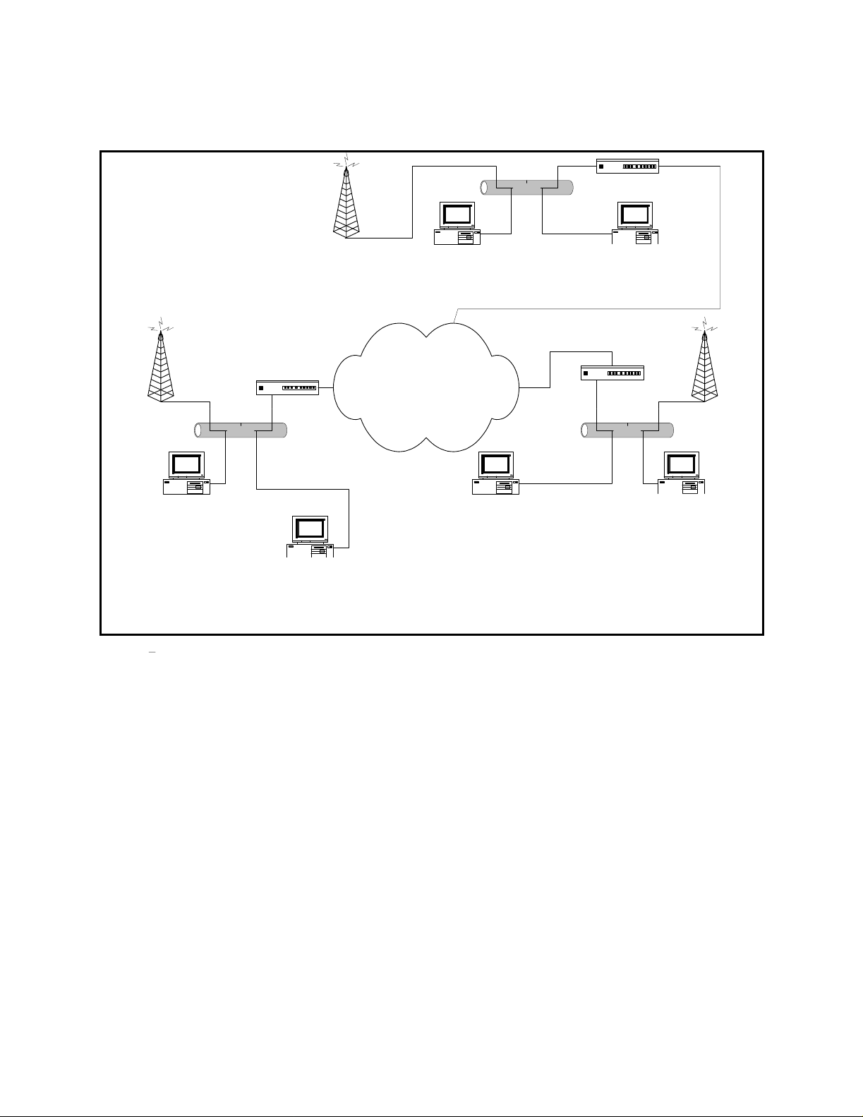
5.3.12 Echo Packets Enable
The Echo Packet function allows the system to operate on networks that do not support multicast. It requires that
the C-Soft application be running at all times to translate and transfer packets from one IP address to another. A
Radio tower 1
10.6.100.100
225.8.11.83
RX:1054
TX:1072
C-Soft
Chan1: RX 225.8.11.83:1054 TX 225.8.11.83:1072
Echo1: RX 10.8.100.200:1054 TX 10.8.100.200:1072
Chan2: RX 10.8.100.201:1055 TX 10.8.100.201:1073
Echo2: RX 225.8.11.83:1055 TX 225.8.11.83:1073
Chan3: RX 10.8.100.200:1056 TX 10.8.100.200:1074
Echo3: RX 225.8.11.83:1056 TX 225.8.11.83:1074
10.6.100.200
Chan1: RX 225.8.11.83:1054 TX 225.8.11.83:1072
Chan2: RX 225.8.11.83:1055 TX 225.8.11.83:1073
Chan3: RX 225.8.11.83:1056 TX 225.8.11.83:1074
Radio tower 2
10.7.100.101
225.8.11.83
RX:1055
TX:1073
Router
C-Soft
10.6.100.201
225.8.11.83
Echo1: Disabled
Echo2: Disabled
Echo3: RX 10.7.100.200:1056 TX
Ethernet
C-Soft
Chan1: RX 10.8.100.200:1054 TX 10.8.100.201:1072
Echo1: RX 225.8.11.83:1054 TX 225.8.11.83:1072
Chan2: RX 225.8.11.83:1055 TX 225.8.11.83:1073
Echo2: 10.8.100.200:1055 TX 10.8.100.200:1073
Chan3: RX 10.6.100.201:1056 TX 10.6.100.201:1074
Echo3: RX 225.8.11.83:1056 TX 225.8.11.83:1074
10.7.100.200
Private WAN
C-Soft
Chan1: RX 10.6.100.200:1054 TX 10.6.100.200:1072
Echo1: RX225.8.11.83:1054 TX 225.8.11.83:1072
Chan2: RX 10.7.100.200:1055 TX 10.7.100.200:1073
Echo2: RX 225.8.11.83:1055 TX 225.8.11.83:1073
Chan3: RX 225.8.11.83:1056 TX 225.8.11.83:1074
Echo3: RX 10.6.100.200:1056 TX 10.6.100.200:1057
10.8.100.200
Router
C-Soft
Chan1: RX 225.8.11.83:1054 TX 225.8.11.83:1072
Chan2: RX 225.8.11.83:1055 TX 225.8.11.83:1073
Chan3: RX 225.8.11.83:1056 TX 225.8.11.83:1074
10.7.100.201
Echo1: Disabled
Echo2: Disabled
Echo3: Disabled
Router
Radio tower 3
10.8.100.102
EthernetEthernet
Chan1: RX 225.8.11.83:1054 TX 225.8.11.83:1072
Chan2: RX 225.8.11.83:1055 TX 225.8.11.83:1073
Chan3: RX 225.8.11.83:1056 TX 225.8.11.83:1074
225.8.11.83
C-Soft
10.8.100.201
Echo3: Disabled
RX:1056
TX:1074
Figure 6 Echo Packet Example Diagram
typically application
might be a number of radios spread throughout a network. Since multicast is not supported, the
radio adaptors (IP-223s or C-6200s) are programmed to send packets to a specific static IP address; the IP address of
the PC running C-Soft with Echo Packet en
abled.
The general functionality of Echo packets is as follows. All traffic received on the address of the RX packet, which
was typically multicast, but under this scenario is the unicast add
ress of the radio remote, is copied and output to the
RX Echo Packet address. In this scenario, the Echo Packet RX address would typically be the multicast address.
This enables the C-Soft to function as a gateway for other consoles on the same local net
work segment. The local
consoles transmit and receive the multicast address only and the C-Soft application translates and sends the packets
to the radio directly. The TX side works in a similar fashion except that packets received on either address are
echoed to the other address and when the C-Soft transmits, it sends to both ports simultaneously.
Figure 6 shows an
example Echo Packet system. The example shows three different radios connected through a WAN. The WAN is
assumed to not pass multicast. In each of the subnets, a single copy of C-Soft is used to do the communications to
the radio within its subnet. A second console is used to echo the audio traffic to other copies of C-Soft on different
subnets. C-Soft will also
added to the system by specifying the multicast address only.
5.3.13
Freqs Button per Line
Pressing the Freqs button on a particular line will open the dialog box for the
dialog is shown in
this box will turn on and off the options for this frequency
echo all traffic to a multicast address within its subnet so that additional consoles can be
settings for that particular line. The
Figure 7. The first column in the dialog box is the Enable checkbox. Checking and unchecking
within the rest of the designer software as well as options
Page 17

17
Figure
within the dialog box. The Frequency Name is a descriptive name
that is used through the rest of the program for referencing the
frequency of the line. It can also be placed on a button
dynami
cally by referencing it as a variable.
5.3.14
There are four available wildcard groups per line. Function tones 1
and 2 are not allowed in a wildcard group and a function tone may
not be part of more than one group. One function tone from eac
group can be active at a time, plus either F1 or F2. This allows for
function tones to have control functions, but that are not used for
actual frequency control of the radio. The dialog box will control
what is allowed and not allowed.
5.3.15
The RX block function is used to mute certain channels when the
current channel is placed into a transmit condition. This allows the
dispatcher to transmit on a radio that has overlapping coverage
with other radios, without getting feedback from the radios that are
receiving the transmitted signal. The setup of the function is
completed by highlighting the lines that should be muted during a
transmit operation. This function also operates when a parallel
console is detected transmitting on the line.
5.3.16
The Backup IP Setup button at the far right of the dialog box is
used to allow for a backup network resource to be used to access a
radio line in the event of a failure of the primary radio interface.
Figure 8 shows the dialog box for this function. A complete second
set of RX and TX addresses are included as well as separate port
numbers for them. A base IP address is also included.
Per Line Pair Mode
RX Block Lines
Back
up IP Setup
h
7 - Per Line Frequency Setup Dialog Box
5.3.17
The Base Radio IP address is used by C-Soft as the destination address of
an internal Ping command. The base radio IP address is periodically
pinged to determine if a network connection still exists t
radio. If no response is received from the ping, the backup IP radio
addresses are used. There is also a backup button that can be used for
force a switch or to monitor the actual channel being used; backup or
primary.
5.3.18
T
for a P25 system externally in a FIPS certifiable manner. It is a standalone
network device which C-Soft uses for the encrypt/decrypt process. The setup
for a JEM device in C-Soft
the Edit menu in designer. The dialog box shown in Figure 9 will open. Type
in the IP addresses of the JEM devices on the network. The JEM device can be
located on the same netwo
separate network that might be local to only the computer running C-Soft. If
this is the case, the JEM Ethernet Interface should be changed to logical number
of the network interface on which the JEM
Base Radio IP
Setup JEM Boxes
he JEM (Johnson Encryption Machine) is a device which does all encryption
o the particular
Figure
is completed by selecting Setup JEM Boxes from
rk as the radio resources, or they can be located on a
devices are located.
8 -
Backup IP Setup
Figure
9 -
JEM Box Setup
Page 18
18
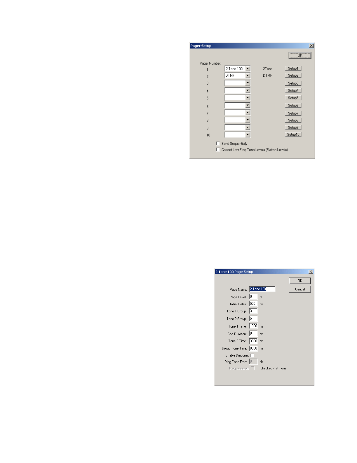
5.4 Paging Encoder Setup
Upon selecting the Paging Setup menu, the dialog box
shown in
the first location for setup of the paging system of the CSoft console. The C-Soft will allow setup of up to 10
simultaneous paging encoder types. The three currently
supported paging encoders are: Quickcall II 100 and 1000
group, as well as DTMF. To setup each of the 10 enc
use the pull down box in the second column to select the
type of encoder. Once an encoder has been selected,
clicking on the setup button on the same row will open the
associated setup screen for the encoder. The setup screens
for each appear in t
5.4.1
Two other options appear in the paging setup box. The first
checkbox enables sequential sending of the paging tones.
When unchecked, pages that are steered to different lines
will go out simultaneously, when checked they will go
sequentially. The RF characteristics of the system will
dictate this setting.
The second option is to correct low frequency tone levels. Depending on the load being driven by the IP-223 or C6200, it is possible that additional rolloff of the levels of the lower frequency tones (sub 1kHz) will occur.
Checking this box will flatten the tones across the 300 to 3kHz spectrum and allow for better level adjustment.
Figure 10 will be displayed. This box is typically
he next sections:
Paging Option Checkboxes
oders,
Figure 10 - Paging Encoder Setup
5.4.2
The setup screen in
pressed from the Paging setup dialog and 2 Tone 100 is selected in the pull down menu. This format requires only a
two di
Name for Paging Setup:
This is a character string which associates a name with the particular
setup for this encoder. The name will be displayed as an optio
Paging Directory dialog box.
Delay before first Tone:
This option is the amount of time allowed from PTT until the first tone
is played
Tone #1 and #2 Group Numbers:
The Tone Group numbers are selected from the top row of
Table 2. These are the standard tables for Two-Tone Signaling.
2 Tone 100 Setup:
Figure 11 is for 2 Tone 100. This is the setup dialog that appears when the Setup button is
git code to generate a paging sequence. Going from top to bottom, the parameters are as follows:
n in the
Table 1 and
Figure 11 - 2
-Tone 100 paging setup screen
Page 19

19
Vega Group No.
Tone Groups
0
1
2
3
4
5
6
7
8
9
Diagonal
1
Mot 1
330.5
349.0
368.5
389.0
410.8
433.7
457.9
483.5
510.5
539.0
569.1
2
Mot 2
569.1
600.9
634.5
669.9
707.3
746.8
788.5
832.5
879.0
928.1
979.9
3
Mot 3
1092.4
288.5
296.5
304.7
313.0
953.7
979.9
1006.9
1034.7
1063.2
569.1
Table
4
Mot 4
321.7
339.6
358.6
378.6
399.8
42
445.7
470.5
496.8
524.6
569.1
1
2.1
5
Mot 5
553.9
584.8
617.4
651.9
688.3
726.8
767.4
810.2
855.5
903.2
979.9
6
Mot 6
122.5
1153.4
1185.2
1217.8
1251.4
1285.8
1321.2
1357.6
1395.0
1433.4
979.9
7
Mot A
358.9
398.1
441.6
489.8
543.3
602.6
668.3
741.3
822.2
912.0
979.9
Vega Group No.
Tone Groups
0
1
2
3
4
5
6
7
8
9
Diagonal
8
Mot B
371.5
412.1
457.1
507.0
562.3
623.7
691.8
767.4
851.1
944.1
979.9
9
Mot Z
346.7
384.6
426.6
473.2
524.8
582.1
645.7
716.1
794.3
881.0
979.9
10
GE A
682.5
592.5
757.5
802.5
847.5
892.5
937.5
547.5
727.5
637.5
742.5
Table
11
GE B
652.5
607.5
787.5
832.5
877.5
922.5
967.5
517.5
562.5
697.5
742.5
2
12
GE C
667.5
712.5
772.5
817.5
862.5
907.5
952.5
532.5
577.5
622.5
742.5
13
Mot 10
1472.9
1513.5
1555.2
1598.0
1642.0
1687.2
1733.7
1781.5
1830.5
1881.0
None
14
Mot 11
1930.2
1989.0
2043.8
2094.5
2155.6
2212.2
2271.7
2334.6
2401.0
2468.2
None
15
Custom
1034.9
953.9
0
0
0
0
0
0
0
0
None
Page 20

20
Entering a number from 1 to 14 in each o
frequencies will be played in succession.
Tone #1 Duration:
Gap Duration:
Tone #2 Duration:
Group Tone Duration: Each of these durations are set in milliseconds and generally conform to the standard
paging plans listed in
Tone #1 (ms)
1000 - 3000 8000
400
0
1000 0 3000 6000 NEC-B
1000
1000 0 1000 4000 NEC-C
400
0
500
0
Table
Gap (ms)
3:
300
3000 6000
f these fields will then select, based on the two digit pager code, which two
Tone #2 (ms)
800
800
500
Group Call (ms)
8000
4000 NEC-M
3000 NEC-L
GE std, Mot std Tone and
Type
Voice
Mot. Tone Only
NE
C-A
400
0
Enable Diagonal Tone:
diagonal tone is disabled, the next two entries are ignored and the second tone is played for the diagonal tone
duration period. When the diagonal is enabled, the diagonal tone (Diagonal Tone Frequency
either the first or second tone depending on the final
and second tones come from the same tone group and are the same number, group call paging is generated.
This checkbox determines if the diagonal tone of a group is used or not. When the
400
3000 NEC-D
Table
3
check box (
Diagonal Tone Location
) is used in place of
). Anytime both the first
Page 21

21
5.4.3
The 1000 group paging mode is similar to the 100 group
paging group e
it a three digit code. The new first digit is used for an
additional table lookup, which then points to two of the
columns in
group setup.
up one of the 1000 encoders.
Name for Paging Setup:
this particular paging setup.
Delay before first Tone:
allowed from PTT until the first tone is played
Tone Plan Number:
from the list of tone plans in
the pager to be reached is N349, the Tone Plan Number
would be set to 12 which corresponds to group N. All pagers
using the N group would then reference this encoder setup in
the listing of all persons. The 3 corresponds to which line in
group N to select the tone groups from. In this case, 3 says to
take both the first and second tone from group number 3
Vega Codeplan #
Pager Capcodes
2 Tone 1000 Setup:
xcept that it adds an additional number making
Table 1 and
Figure 12 shows the entries required for setting
Table 2, listed previously i
A 10 digit name associated with
This option is the am
The tone plan number is selected
Table 4,
1
Mot B
2 Mot C
ount of time
Table 5, and
3 Mot D
4 Mot E
n the 100
Table 6. If
Figure 12 - 2-Tone 1000 paging setup dialog
5 Mot F 6 Mot G
7 Mot H
8 Mot J
9 Mot K
2+4
N/A
N/A
0xx
1+1
1+1
1xx
2+2
2xx
3xx
4xx
5xx
6xx
7xx
8xx
9xx
(3+3). So, for N349, the first tone sent would be 313.0 for 1
Tone #1 Duration:
Enable Diagonal Tone: Diagonal Tone Frequency:
3+3
1+2
1+3
2+1
3+1
2+3
3+2
2+2
1+2
4+4
1+4
2+1
4+1
2+4
4+2
Gap Duration: Tone #2 Duration:
1+1
2+2
1+2
1+5
5+5
2+1
5+1
2+5
5+2
N/A
1+1
2+2
1+2
2+1
1+6
6+6
6+1
2+6
6+2
Table
N/A
1+1
1+3
3+3
4+4
3+1
1+4
4+1
3+4
4+3
4
second, followed by 1063.2 for 3 seconds.
N/A
N/A
1+1
1+1
1+3
1+3
3+3
3+3
3+1
3+1
5+5
1+6
1+5
6+6
5+1
6+1
3+5
3+6
5+3
6+3
Group Tone Duration:
Diagonal Tone Location:
N/A
1+1
1+4
4+1
4+4
5+5
1+5
4+5
5+4
5+1
N/A
1+1
1+4
4+1
4+4
1+6
6+6
6+1
4+6
6+4
These are the same entries as the previous section in
Table
3.
Page 22

22
Vega Codeplan #
Pager Capcodes
0xx
1xx
2xx
3xx
4xx
5xx
6xx
7xx
8xx
9xx
Vega Codeplan #
10
Mot L
N/A
1+1
1+5
5+1
1+6
5+5
6+6
6+1
5+6
6+5
18
11
Mot M
4+2
2+3
2+2
3+3
4+4
3+2
2+4
4+2
3+4
4+3
19
12
Mot N
4+2
2+3
2+2
3+3
3+2
5+5
2+5
5+2
3+5
5+3
20
13
Mot P
4+2
2+3
2+2
3+3
3+2
2+6
6+6
6+2
3+6
6+3
Table
21
5
14
Mot Q
4+2
2+4
2+2
4+2
4+4
5+5
2+5
4+5
5+4
5+2
22
15
Mot R
4+2
2+4
2+2
4+2
4+4
2+6
6+6
6+2
4+6
6+4
6+5
23
16
Mot S
4+2
2+5
2+2
5+2
2+6
5+5
6+6
6+2
5+6
24
17
Mot T
4+2
3+4
4+3
3+3
4+4
5+5
3+5
4+5
5+4
5+3
25
Pager Capcodes
0xx
1xx
2xx
3xx
4xx
5xx
6xx
7xx
8xx
9xx
Mot U
Mot V
Mot W
Mot Y
4+2
3+4
4+3
3+3
4+4
3+6
6+6
6+3
4+6
6+4
Mot
MT
4+2
4+2
N/A
4+2
3+5
4+6
7+7
1+1
5+3
6+4
8+8
2+2
3+3
5+6
9+9
1+2
3+6
4+4
7+8
4+4
5+5
5+5
7+9
5+5
6+6
6+6
8+7
2+1
6+3
4+5
9+7
4+5
5+6
5+4
8+9
5+4
6+5
6+5
9+8
2+4
Table
6
GE X
10+10
11+10
11+11
10+11
12+12
12+10
12+11
10+12
11+12
N/A
GE Y
11+11
12+11
12+12
11+12
N/A
N/A
N/A
N/A
N/A
N/A
GE Z*
10+10
12+10
12+12
10+12
N/A
N/A
N/A
N/A
N/A
N/A
Page 23

23
5.4.4
DTMF paging is also supported in the C-Soft console. The
standard DTMF digits are allowed in any length. Figure 13
the web setup required for enabling DTMF paging. The entries
are similar to those before.
Name for Paging Setup:
particular paging setup.
Delay before first Tone:
allowed from PTT until the first tone is played
Digit On Time:
Digit Off Time:
played and the spacing between digits.
Total Page Digits: The number of digits in a standard page. All pages that utilize this option will expect this
numbe
5.4.5
There is also a manual page button that allows setup of up to 5 tones of programmable frequency and duration. See
the user interface elements listing for the Manual Page button.
DTMF Paging:
The amount of time for the DTMF digit to
r of digits.
Manual Paging Entry
A 10 digit name associated with this
This option is the amount of time
shows
Figure 13 - DTMF Paging dialog
Page 24

24
5.5 Global Setup
The Set Global Parameters dia
menu and is shown in
in the following sections.
5.5.1
Two options are available for setup that affect the operation of
the DTMF keypad keys should the
screen. The first parameter is the Flywheel. This is the amount
of time the user has to go from one key to another key without
the console keying down the radio. The console will
automatically keyup to transmit if a DTMF key
second option is the relative level to be transmitted. The actual
level transmitted by the radio will vary depending on the system
between the console and the actual radio. This could include the
TX pot setting of the radio, settings within the radio, etc. This
value exists to allow the designer to turn up or down the relative
level that gets transmitted once the remainder of the system is
aligned and operational.
5.5.2
By programming this value to something other than zero, if the
console sees no activity on both TX and RX of the supervised
lines for the programmed amount of time, the lines will be
released from supervision. In addition, this value is used when
the
forgot to release the supervisor function, after the programmed
period of no activity at the console, the supervisor release command would be sent out. A value of 0, disables the
timer.
DTMF Setup
Supervisor Timeout
Supervisor key is pressed such that if the console operator
log box is selected from the Edit
Figure 14. The parameters are discussed
designer place them on the
is pressed. The
Figure 14-Global Properties Se
tup
5.5.3
Up to 10 addresses can be entered for the Local IP addresses. These addresses should correspond to the base IP
address of the other C-6200 and C-Soft consoles within the same room. This list is used for the Ethernet c
function. The C-Soft examines the source of the audio and flags it if the source was from a console in this list. If
the source of the TX audio is from a console with an IP address within this list, the audio will then be muted. The
only except
be routed to the headset earpiece, it will be played, ignoring the crossmute condition.
A second method exists starting in version 2.62 to create
csoft_crossmutes.txt in the directory it is executed from, it will load up to 10 IP addresses, one per line, from this file
and replace the settings in the global settings dialog. This allows for a posi
without requiring a different design file.
Starting in version 2.93, the limit on the number of crossmute IP addresses in the csoft_crossmutes.txt file was
increased to 20.
5.5.4
Computers can contain more tha
utilize either any of the first four interfaces. Because the runtime software is not necessarily executed on the same
PC as the software to design the user interface, some experimentation may be required. If no traffic is seen on the
desired Ethernet interface, changing this option, saving the file, and restarting the console may correct the problem.
5.5.5
Beginning in version 2.1 of the C-Soft package, an exte
allows connection of standard dispatcher accessories including a deskmic, 2 headsets, and footswitches. It also has a
connection to the serial port of the PC. It is through this serial port
Local Con
ion to this muting rule is if the HB3 is connected and the headset is turned on. If the received audio is to
IP Interface
HB3 Serial Port
sole IP Address / Ethernet Crossmute
n one Ethernet interface. For this reason, the software console can be configured to
rossmute
crossmutes. If CSoftruntime.exe finds a file called
tion to have its own crossmute settings
rnal audio interface is supported. This unit, called the HB
that messages are sent and received from C-Soft
-3,
Page 25

25
to detect the PTT events. This functionality allows the C
without requiring the dispatcher to move a mouse cursor to the C-Soft application. It also fu
Soft application does not have the focus. Use this pulldown option to select the serial port that the HB-3 is
connected to on the PC or disable it.
5.5.6
In addition to supporting a local key attached to the PC, a remote key
management. A single PC is loaded with the key management driver. Up to 10 individual keys can be connected to
this server PC. Five of each key type are supported by the dongle driver software. This means that 5 USB
Parallel port keys can be connected to the server. Once the server is setup, each client computer (with the Dongle
Driver installed) has the License Server field filled in with either the direct IP address or the network name of the
server. The ser
advantage of making the C-Soft software more portable across a network. Contact the factory for license server
options in which more than 10 concurrent lice
entry of dual mode to be put in as the license server (no quotes). This option tells the console to first look for a
key on the local machine. If no key is found, send a broadcast look
allows for multiple license servers reside on a network for greater redundancy and fault tolerance. It is a slightly
slower bootup however.
5.5.7
Several of the standard windows control buttons can
the window. It is important to note that if the Close button is removed, the only way to shutdown the application is
to use the Windows Task Manager. The open on activity will automatically o
indications are occurring within it.
5.5.8
A customer supplied bitmap logo can be included with the screen design. It will not show up in the designer
program, but only in the runtime version. The file must
executed from. The filename is a maximum of 20 characters. Once the filename is entered, select the screen
placement of the bitmap with the pulldown menu.
License Server
ver will then allow up to its key count number of concurrent users of C-Soft. This method has the
Windows Controls
Bitmap Logo Setup
nses are required. An options, which is new in 2.62, allows for an
-Soft application to respond to PTT s from a footswitch
nctions even if the C
sever can also be used for license
and 5
ing for license servers on the network. This
be selectively added or removed from the upper right corner of
pen a popup window if line activity
be a bitmap and be located in the directory that runtime is
-
5.5.9
The background color
Black is the default.
5.5.10
Three checkboxes are displayed to allow control of audio routing. Set these per dispatcher preference.
5.5.11
When checked, the ANI displayed on the Select button will be left on the Select button until the next call is received.
5.5.12
Checking the Kill Lines on Crosspatch option will disable the dispatcher s ability to transmit
put into a crosspatch by a parallel dispatcher. Leaving the option un-checked, allows the dispatcher to use the lines
even though another dispatcher has them in a crosspatch.
5.5.13
The Radio Ping interval is the time
(0) will disable the function as will not filling an IP address in the IP Setup Dialog. A typical value would be 300
seconds or five minutes. See section
5.5.14
The RX Block Delay setting is used to delay the release of the RX Blocked lines (setup in the frequency settings
dialog boxes). The purpose of this is to allow IP and system de
Background Color
for the console and its popup windows can be set by pressing this button and selecting a color.
Audio Routing and Muting
Enable S
ticky ANI
Kill Lines on Crosspatch (2.7)
Radio Ping Interval
RX Block Delay
in seconds between Ping attempts on the Base Radio Address. A value of zero
5.3.17
for more information about the Base Radio IP setup.
on a line that has been
layed audio to end before releasing the mutes.
Page 26

26
5.5.15
Version 2.93 of the C-Soft product added sidetone output for tone generation. This includes DTMF and single tones
such as paging and alert tones. This setting controls the l
5.5.16
This setting is primarily used with the iDen interface of the IP-223. When a call comes in from the iDen device, the
serial data that gives caller information lags the audi
and the caller ID information coming through, the IP-223 will delay telling the consoles what channel (Function
Tone mapping) the caller is on. By checking this box, the frequency update inform
point in the RX stream. With this box unchecked, frequency update information is only accepted at the beginning of
a call, before audio playback is begun.
5.5.17
Starting in Version 2.58, C-Soft supports a Software based microphone AGC. This function helps to level speech
level variations caused by use of different microphones, different speaking distances to the microphone, and
different volumes of speech from different users. The Enable checkbox is the
to enable this function. The Target level is the audio level that the packets are adjusted to. If the measured audio
level is above the target level, the audio is reduced in gain. If the incoming level is below the
gain is applied to bring the level up. The last option is the Minimum Active Level setting. This setting is used to
tell the AGC software when to quit trying to adjust the audio level. If audio below this level is detected, the AGC
will attempt to make no adjustments to the audio. This prevents open mics from amplifying background noise onto
the transmit channel.
5.5.18
Enter the IP address and port number that the ring signal will be broadcast to. This sh
set in the C-6200 that has the actual phone card physical interface.
Tones/DTMF Sidetone Level (2.93)
Allow Freq Update Anytime (2.93)
MIC AGC Enable and Settings
Phone Ringer Multicast and Port
evel of the tones that are output to the speaker.
o. Because of this lag between the call audio coming through
ation will be accepted at any
left most option and must be checked
target, up to 15dB of
ould correspond to the values
5.5.19
The NEO-10 Network I/O device sends out a UDP packet anytime one of its inputs or outputs changes state. C-Soft
monitors this
desired multicast and port number in these fields. They should match the values entered into the NEO-10 Multicast
setup screen. This is not the base I
5.5.20
The positional recording options allow for audio from a console position to be sent directly to a recorder. Each
speaker and the microphone can be independently sent to the Veg
audio sources that need to be recorded. The microphone is only recorded during activity such as PTT or a telephone
call. The typical IP address entered for each of these options is the static IP address of the
The network recorder is then set to look for packets from this position. The ports must be unique on the system.
This option will require, if multiple consoles are in use, a separate configuration for each console be created.
NEO Multicast and Port Numbers
traffic allow all users of the equipment to see changes in the status of inputs or outputs. Enter the
P address as is used for the individual buttons.
Positional Recording Settings
a Network Recording device. Enable only the
Vega Network Recorder.
Page 27
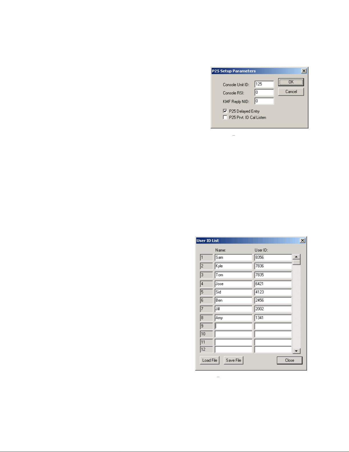
27
5.6 P2
P25 requires some specific setup parameters be entered for correct function of the console. These parameters were
located in the Global Settings dialog box prior to version 2.56 but have
been relocated and augmented.
displayed when the P25 setup option is selected from the Edit menu.
5.6.1
The Console ID is entered to allow unique identification of the console
during a transmission and for User ID calls.
5.6.2
The Console RSI is used for over the network re-keying operations.
The only currently supported KMF is the one made by EF Johnson.
Contact EF Johnson for more information.
5.6.3
When using a KMF to
the NAC code being used by the KMF in this location. A common value is 659.
5.6.4
Checking this box will cause the console application to resend the Header p
superframe for the purpose of late entry.
5.6.5
This function, when enabled, allows the dispatcher to listen to Private Calls. With this option unchecked, private ID
calls are indicated on the dispatc
5 Setup Menu
Console Unit ID
Console RSI
KMF Reply NID
P25 Late Entry
P25 Private ID Call Listen
manage encryption keys, a specific NID or NAC must be used for response messages. Enter
Figure 15
hers screen with an icon on the Select button, but the audio is not played.
shows the dialog box
Figure 15 P25 setup parameters
acket(s) at the beginning of each
5.7 User ID List
The User ID list is used with the ANI features of certain radios.
As of the writing of this manual, P25, Fleetsync, and MDC1200
user IDs are supported.
data entry. The Name is the string that will be placed on the
Select button of the line where the ANI is received. The User ID
value is the actual number the radio transmits as its identifier. If
desir
ed, the Sticky ANI feature in the Global Setup dialog can be
used to have the alias placed on the Select button until the next
call comes.
In addition to allowing manual entry, a comma delimited file can
be loaded from disk allowing for a central list to b
in a spreadsheet or other file format and then imported into the
console design. The file must take the form of Name, ID. Only
one name and ID can be entered per line.
Figure 16
shows the dialog box for this
e maintained
Figure 16 User ID List
Page 28

28
5.8 Crypto Key Entry (P25
The forth option under the Edit menu is the Crypto Key entry
dialog box. Up to sixteen crypto keys can be entered. Each of
these keys is referenced by a 16 bit index value as well as a 64
bit key. The digits 0-9 and A-F are supported for the key
Selection of this menu item will open the dialog box shown in
Figure 17
button will close the dialog box and save the entered values.
. Once the keys have been entered, pressing the OK
5.9 Interface Item Manipulation
A number of possible manipulations of the user interface items are possible. Not all options are supported on all
items. A number of the standard windows shortcuts are also supported.
designer application.
5.9.1
Most of the edit menu commands can
also be accessed by toolbar buttons and
also by right clicking on the eleme
itself and selecting from the popup
menu that appears. Each of the buttons
on the toolbar are shown with a line to
the menu command that will perform
the same operation. Beginning in
Version 2.5, standard clipboard options
exist. A group of objects ca
selected by clicking on an open space
and dragging a rectangle over the items
to be included in the selection. When
the left button is released all items
completely contained within the
rectangle will be added to the selection
group. This group can
Copied, or moved. By right clicking on
an object within the selected group, the
groups Line Number association or its
Font can be changed.
currently possible to move a group of
objects with the mouse.
Edit Menu Options
nt
n be
then be Cut,
Note that it is not
Only)
s.
Figure 17 Encrypti
Figure 18
Figure 18 Interface Element Edit Options
on Key Dialog Box
shows the main screen of the
5.9.2
Th
an element. The CTRL-X shortcut key is also active. When selected from the menu, the interface object with the
target drawn on it will be d
deleted from the window as well as the base popup button.
5.9.3
This function operates in the standard windows way.
valid group of objects has been copied, the Paste function will become active.
Delete Items (Cut)
ee other options exist in the Edit menu that have not be previously mentioned. The Cut function is used to delete
Copy Items
eleted. In the case of the a popup window with multiple object within it, all items are
Cut objects are not saved to the clipboard!
An object or objects that are selected can be copied. Once a
Page 29

29
5.9.4
When a group of objects has been copied, the Paste function becomes available. The Paste function will
currently active view for its placement. To copy from one Popup to another requires that the objects be selected and
copied in the first window, and that the destination Popup window be selected before the Paste function is selected.
5.9.5
If the button is a popup menu button, having the target active on it and selecting the Open Popup option from the
Edit menu or by right clicking on the button, will open the button within the designer so the elements within it can
be edited.
5.9.6
The Properties selection, available from the edit menu or by right clicking on the item of interest, opens a paged
dialog box with the properties pertinent to the function of the element. The function of the element can be changed
as well
5.9.7
Individual objects can be moved by clicking on them and dragging them to a new location. In addition, a
button/slider/popup copy function is supported by holding down the CTRL key while moving the object with the
mouse. This will copy the item exac
only a couple minor changes are required to use the button. It is also much faster than moving to a menu for each
operation.
Paste Items
Open Popup
Properties
.
Drop, Drag, and
Copy
tly with all parameters in tact. This is very useful for copying elements where
look at the
Page 30
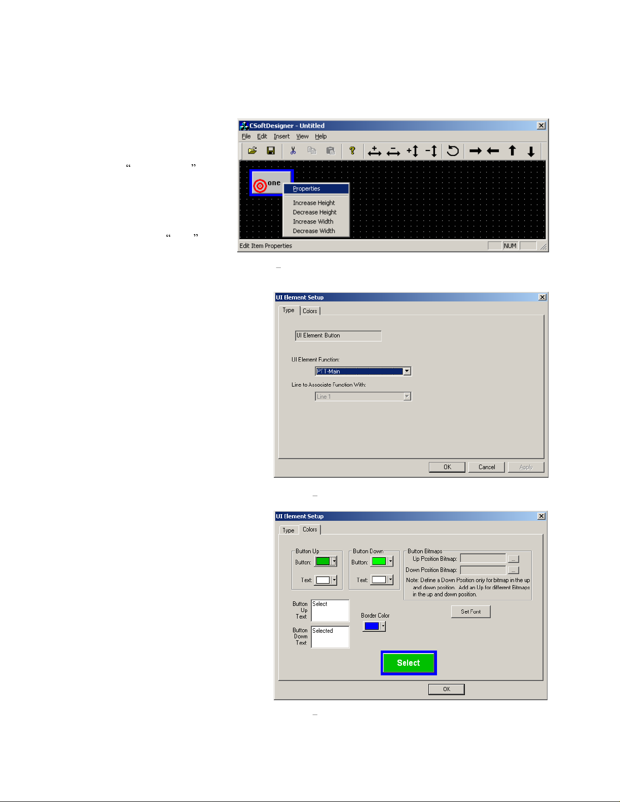
30
5.10 User Interface Element Reference
The insert menu has options for
inserting a button, a slider, and a
popup window. Buttons are the
predominant user interface element.
By selecting Add UI Button from
the Insert menu, a generic button will
be
placed into the upper left corner of
the screen. The text on it will read
none. The button is selected by
clicking on it. Once a button is
selected, it will have a target drawn
on it signifying that operations
selected from the menus or button bar
wil
l occur to this particular element.
Figure 19
results after right clicking on the button.
Selecting Properties brings up the standard
front screen for all user interface elements.
Figur
two tabs exist. The default first tab is the Type
tab. This tab contains information pertaining
to the function of the button. The first pull
down, UI Element Function, is a list of all
supported functions that
Each of these functions, as well as their
specific settings will be discussed in the
following sections. The second pull down is
only active when button functions that require
specification of the associated line are
selected.
shows the popup menu that
e 20
shows this dialog. In the base case,
the button can have.
Figure 19 Button Properties
The second tab, Colors, is used for setting the
text and colors of the button. Selecting a
function will place default values for text and
color on t
dialog. This example shows a button with
defaults set if the button is to function as a
Select button. Colors for the button and text
can be changed for both the up and down
positions. Text can be spe
position. Multiple lines of text can be placed
on to the button by pressing CTRL-Enter to
move to the next line. Some functions
automatically place additional lines of text
onto the Select button, so leaving additional
space on the button
idea. The border color can also be specified.
The border is half of the grid size. This allows
buttons to be grouped with the same color
he button.
Figure 21
for text generally is a good
shows the
cified for each
Figur
e 20
Main Properties screen
Figure 21 Color Setup
Page 31
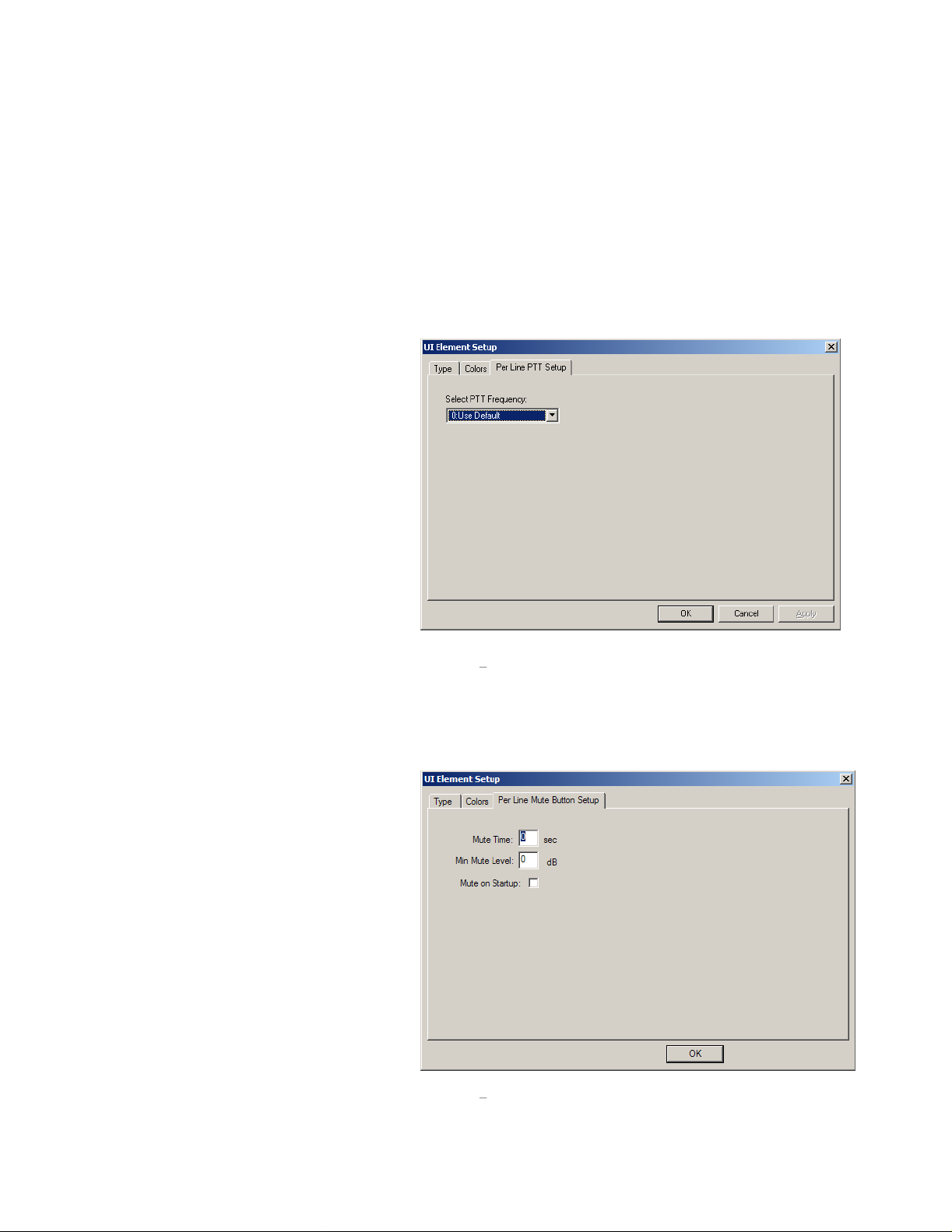
31
border. This helps to create visual separation between groups. The font can be adjusted by pressing the Set Font
button. A bitmap can also be added to the button by selecting the desired bitmap files. The Bitmap files must be
resident in the CSoftRuntime directory for them to be used by the program. If the bitmaps are not found by runt
they simply will not be displayed.
ime,
5.10.1
5.10.1.1
The main PTT button is the most recognized button on the console. Generally all consoles will have one. When
pressed, audio present on the sound cards mic input, will be encoded and se
Main selection has no additional setup parameters and does not require a line to be associated with it.
5.10.1.2
The Per Line PTT, or Instant PTT, function is
used to immediately key up one particular line
on the
function, when selected for a button adds a
third tab to the dialog box that allows a PTT
Per Line button to move to a specific
frequency. The default is option 0 which is to
use the currently selected frequency. Open
the drop-down box lists frequencies that are
available on the line selected in the Type tab.
Figure 22
Line PTT Setup tab is chosen.
5.10.1.3
The PTT Talkback button keeps track of the
last line that audio was received from. When
pressed, it will transmit to that line.
5.10.1.4
The Mute Main selection is the option for a global mute key. When the user presses this button, all lines
currently selected will be muted. If the line is currently selected, it will be unaffected. No line selection is required
and there are no additional setup parameters.
Button Function List
PTT-Main
PTT-Per Line
current frequency. The PTT-Per Line
shows the dialog box when the Per
PTT-Talkback
Mute Main
ing
-
Figure 22 PTT-Per Line
nt to all Selected channels. The PTT
dialog tab
that are not
-
5.10.1.5 Mute Per Line
The Mute Per Line button is used to mute a
particular lin
active when pressed and inactive when
released. If a Mute Per Line button is
associated with a phone line and active, ring
tones on the line will be muted until the line is
offhook. Once the line is offhook, the Mute
Pe
r Line button becomes inactive.
A line for the mute to affect must be chosen
from the Type tab.
box that appears when the Mute Per Line
option
customization of the function of the button.
The first is a mute timer. Entry of a value in
this box will force the mute to deactivate itself
automatically after the entered number of
seconds. A value of zero disables the fe
e. It is a latched button that is
Figure 23
is set. Three options allow
shows the dialog
ature.
Figure 23 Mute Per Line dialog tab
Page 32

32
The second option is for setting a minimum level while muted. A value of 0 entered will cause the mute to turn off
the unselect audio completely. The remaining options of
the unselect audi
turn off audio completely that should be monitored. When the Mute button for a particular line is active, the lines
volume control is also disabled. Th
the program is started. When upgrading from older designs, this check box may have to be checked and unchecked
for the options to take effect.
o played at the speaker. This has the effect of making sure that the dispatcher position is unable to
e last option is a checkbox to have C-Soft automatically enable the mute when
20 to
1 apply a cut in the audio level to merely reduce
5.10.1.6
The Mute Group opt
preprogrammed number of lines to be muted
by pressing this button. The Mute Group
button has a third tab that allows for selection
of the lines to be muted when this button is
pressed. Clicking once on a line in the list will
include the
will remove the line from the list of lines to
mute. No line selection is required for this
button.
5.10.1.7
The Select button is a common staple on most
console
button that is used for determining which channels will be transmitted on when a master or accessory PTT button is
pressed. DTMF and Alert tones are also
transmitted to all selected lines. The select
button is also
line. Indications such as audio receive,
transmit, crossmute, intercom, encrypted,
collision, and supervisor are all indicated on
this button by the console.
It is possible to customize the actual icons
used for Tx, Rx, Inte
Be default these are small circular LEDs
with a letter or two in them. To replace each
of these default icons with one of the users
choosing, place a file named txled.bmp,
rxled.bmp, icled.bmp, and/or xtxled.bmp
into the directory
found, these user bitmaps will replace the
default bitmaps. The background color of
RGB(192,192,192) is transparent when
placed onto the button. (BMP must be
24bit)
Th
e third tab of the Select button is used for
Select Call. The C-6200 and IP-223 have built
Mute Group
ion allows for a
line; clicking on it a second time
Select
screen designs. It is a toggle on/off
used to indicate activity on a
rcom, and Crossmute.
with CSoftRuntime.exe. If
Figure 24 Line Group Selection
Figure 25 Select Call Setup Tab
Page 33

33
in DTMF decoders and embed this decode
information into the IP packet stream. The
stream can then be decoded and used to notify
a dispatcher of an outside call. E
required to activate the select call feature.
Multiple options are supported for
annunciation of the select call sequence being
detected. The Select button can be set to
blink. Audible alarms can be activated and the
Mute button, if acti
programmed period of time. In addition, the
digital inputs of the IP-223 can be used to
place further criteria on the Select call. The
DIGIO 0-6 pins of the IP-223 can be used to
sense events in the field. The bits are available
in both active high and active low
configurations. If multiple bits are chosen,
they must all be true for the Select Call
function to operate.
5.10.1.8
The Alert button is added to the user interface
when the dispatcher requires a method to send
some sort
to all selected lines when pressed. If PTT is
not active when an Alert
Alert
of tone. The Alert tones are played
ve, can be opened for a
nter the digits
Figure 27 Alert Tone Setup Parameters
button is pressed, the PTT button is
automatically activated to key up the remote
radio
s before the tones are generated. A
number of options exist in the third tab for
setting up this sound.
Alert Setup dialog tab. Three general types of
tones are available. A single steady tone, a
pulsed tone
type has parameters that allow customization
of the tone sent. The dialog box will grey out
the entries that are not required for a particular
tone type. The Tone Level input is available
for all tone types and allows a r
in the level of the tone generated.
, and a Hi-Lo warble. Each tone
Figure 27 shows the
elative change
Figure 26
Page Options Dialog Tab
5.10.1.9 Page
The Page button is used to send a single page to a particular line and on a particular frequency. The setup options,
shown in
this button. The Talk Time is amount of time after the page is sent for the dispatcher to add a voice message after
the page. The
Figure 26
, require that the paging encoders be setup prior to setting up the specific page associated with
Page String is specific to encoder selected.
Page 34

34
5.10.1.10
The Page Stack key toggles on and off to
allow a number of pages to be selected and
sent in succession. Normally, with this
button not
console interface, a page is sent the moment
the Page button is pressed. When pressed,
all Page keys that are pressed will latch on
giving the console operator an indication of
which pages are selected. The group of
pages is
button is pressed. The page stack key is not
associated with a line and has an option to
unlatch the stack button after the last page is
sent. When the box is checked, as shown in
Figure 28
automatically unlatch after the last page and
will not stack subsequent pages.
5.10.1.11
As mentioned in the Page Stack section, the Page Send button is added to the interface to send a group of selected
pages. The console opera
page recipients. No line or addition setup parameters are required for this button.
5.10.1.12
The Frequency Change button is another staple of a multi-frequency remote radio dispatch operation. This button,
when pressed, will sent a burst of packets onto the Ethernet requesting that the remote radio change to the new
frequency. In addition, all other consoles on the network will also change their displays
of the radio on that particular line. A line must be chosen for this function, and based on that line selection, a third
tab in the dialog box allows the buttons frequency to be set. The frequency selection is identical to that
Line PTT in section
clicking on this button will bring up a floating menu that allows the user to add or remove this channe
list. When a frequency is in the scan list, a SCAN icon appears on the frequency change button. Parallel consoles
are also alerted to update their display if a frequency is added or removed from the scan list.
Page Stack
pressed, or absent from the
then sent when the Page Send
, the Page
Page Send
Frequency Change
Stack button will
tor is notified when the last stacked page is sent so that a voice message can be sent to the
5.10.1.2
. In addition, if the Scanable option was set in the Line IP Setup screen, then right
Figure 28
Page Stack Dialog Tab
to show the new frequency
of the Per
l from the scan
5.10.1.13
Given t
overwhelm the dispatcher, it is common to place the frequency selection buttons into a Popup window. The
dispatcher opens this popup window to chang
window closed, it become impossible to see exactly what frequency is currently selected for that line. To see the
frequency when the window is closed, enter the string $FREQx$ into the po
line number (Section 5.3.3
when it changes. See the example design for more information on actually doing this. The frequency variable can
be placed into any button, but is typically used on the Popup or Select buttons for that line.
5.10.1.14
The Group Select button, when pressed on, is used to allow multiple lines to be selected simultaneously.
sometimes referred to as simul-select. No line or other setup information is required.
5.10.1.15
The Group Programmed button works similarly to the Mute Group button discussed in section
difference
condition. This allows for a dispatcher to create a predefined broadcast group that can quickly be selected for
broadcast.
Frequency Variable
hat the frequency can be changed, and conceivably placing a button for every frequency on every line could
). The actual text for x lines frequency will automatically be updated on the button
Group Select
Group Programmed
is that when this button is pressed, the lines that are configured in the third tab, are placed into a select
e frequencies and closes it after they are done. However, with the
pup button s text where x equals the
It is also
5.10.1.6
. The
Page 35

35
5.10.1.16
The TX all but
all lines into a selected mode. A subsequent PTT
would then transmit on all lines.
5.10.1.17
The RX all cancels mutes on all unselected lines.
It does not change the select status of a line. No
setup is required for th
TX All
RX All
ton requires no setup. It will place
is button.
5.10.1.18 DTMF Digit
Selecting DTMF Digit adds one digit of the DTMF
keypad. All 16 pairs are supported. The DTMF
digit is played to all selected lines either during a
PTT operation or it will g
its own.
selection tab. Creation of a 12 or 16 digit pad is
best accomplished by creating one single digit and
then copying the digit with the CTRL key and the
mouse. Last of
5.10.1.19
The Monitor button is used to send a packet burst, similar to a frequency change, to tell the remote radio to open
squelch or ignore CTCSS tones. No setup is required
Figure 29
all, all key s properties are edited to set them to the correct digit and text.
Monitor
enerate PTT if pressed on
shows the DTMF Digit
Figure 29 DTMF Digit dialog tab
for this button.
5.10.1.20
The Intercom button is used to allow communications between consoles without keying the remote radios. The
Intercom button works exactly like the Main PTT button except that additional information is included that tells the
tone
termination panel not to generate PTT and key the radio. Not setup is required for this key.
5.10.1.21
The Instant Intercom button is used to talk between dispatchers without keying the radio connected to the line. The
difference between this butt
transmit on the selected lines.
5.10.1.22
The Crosspatch button allows the dispatcher to
connec
so that persons communicating through different
lines can talk to each other.
crosspatch group selection tab. Up to 10 patches
are supported by the software console. Once
crosspatch button is placed on the console
screen, lines are added into and out of the patch
by first pressing the Crosspatch button and then
pressing Select buttons. The Select buttons will
change color and text to indicate they are now
part of a cros
of a crosspatch will be transmitted to all other
lines of the crosspatch. The patch can be
dropped by pressing each select button in the
patch again, or by including a Crosspatch Clear
button.
Intercom
Intercom-Instant
Crosspatch
t two or more radios/phone lines together
spatch. Receive traffic on one line
on and the standard Intercom button is that it works on a predetermined line and does not
Figure 30
shows the
a
Figure 30 Crosspatch Group Selection Tab
Page 36

36
5.10.1.23 Crosspatch Clear
The Cros
group in the third tab, all lines selected into the patch will be release from it. It is generally a good idea to have a
Crosspatch Clear button as a quic
spatch clear button requires the same setup as the Crosspatch button. Based on the programmed patch
k way to end a patch.
5.10.1.24
The Crosspatch Block function is used to block a particular line from transmitting. For example, if a particular line
is stuck in receive due to noise, that line can be blocked which releases its control of the cross
has been through one transmit cycle, it is then again eligible to control the patch.
5.10.1.25
A programmed crosspatch allows the
dispatcher to quickly create a crosspatch
between any number of pre-determined lines.
One
the third tab of this button, select the lines
that should be included in the crosspatch when
this button is pressed as shown in Figure 31. It
is suggested that a unique color be used for
this button as its color will be given t
lines in the crosspatch when it is pressed. In
addition, just like in the previous crosspatch
button setups, a crosspatch group number must
be chosen and it must be unique. The
Autostart Crosspatch checkbox can be utilized
to have the crosspatc
when the program is started.
Crosspatch Block
Crosspatch Programmed
h automatically be created
o all the
patch. After the line
Figure 31 Programmed Crosspatch Setup
Page 37

37
5.10.1.26
The Supervisor button is used to allow a single
di
spatch location to grab complete control of a line
or group of lines. When the Supervisor button is
pressed, a 4 digit code must be entered. This code
is entered in tab three of the Supervisor button
setup tab shown in
of the console interface to set this 4 digit code.
After entry of the code has been completed, a
supervisor packet burst is sent out to all selected
lines. The consoles that receive that packet burst
then have those lines removed from th
control. The operator of those lines can neither
hear receive traffic or create transmit traffic. A
period of inactivity can automatically turn off the
supervisor function. See section 5.5.2
the supervisor ti
5.10.1.27 Page
The Manual Page button is similar in use to the
Page button referenced in section 0. However, this
button allows a designer to incorp
single tones in sequence. Frequency and duration
are all programmable. The frequency values will
accept a decimal point.
such as lead in delay, talk time, frequency to send
the page on, an
defined in the first tab of the buttons properties or
it goes to the selected channel are all settable.
Once created, the button can be stacked using the
Page Stack and Page Send buttons.
Supervisor
mer.
d whether the page goes to the line
Figure 32, all
Manual Entry (2.7)
Figure 33
ows the designer
eir local
on setting
orate up to 5
Other functions
Figure 32 Set PIN tab for Supervisor button
Figure 33 - Manual Page Setup
Page 38

38
5.10.1.28
The Instant r
operator to play back a pre-determined amount
of audio. The software console constantly
maintains a record of the last 1800 seconds of
both parallel transmit and receive audio traffic.
Figure 34
Multiple buttons can be placed on the screen.
Each button can be set to play back up a certain
period of audio, either select or unselect. New in
version 2.52 allows the IRR to only record audio
when a call is active. This,
IRR time allows for a long conversation to be
replayed without worry of loss of audio.
5.10.1.29
The EFJ-Select option functions identically to
that of the norma
section
5.10.1.30
The EFJ-Per Line PTT option functions to that of the
is required to be used for a P25 channel. See section
discussion of the Instant PTT function.
Instant Recall
ecall button allows for a console
show
s the setup for the button.
P25-Select
l Select button except it must be used when a console is controlling a P25 base station radio. See
5.10.1.7
for further discussion on the Select button.
P25-Per Line PTT
along with the longer
Figure 34 Instant Recall Recorder Setup Tab
standard Per Line PTT. It
5.10.1.2
for further
5.10.1.31
This button is pla
encryption on a particular channel. If a P25-Encryption button is associated
with a Vega line type, that line must be connected to a Telex IP25300
standalone network device for the button to funct
number is set for this button and on the third tab which encryption key should be
activated. When the button is associated with a Vega channel, CSoftRuntime
does not use the options on the third tab.
5.10.1.32
The User
specific user to call.
defined Users (see
User ID is selected, the button will display the selected ID and all subsequent transmissions will go out in the User
ID call fo
5.10.1.33 Emergency Cancel
The P25, Fleetsync, and MDC1200 radio formats support an emergency function. When received, the console will
play an emergency hi-lo tone to the select speaker to notify the dispatcher of the emergency event. In addition, on
the l
ine that received the emergency call, the Select button will blink between its predefined color and red. Pressing
the emergency cancel button will stop the hi-lo tone as well as the blinking of the Select Button. This button is
typically pressed by the d
Emergency Cancel button also sends a parallel update to other consoles which ends the emergency indication on
their consoles as well.
P25-Encryption
ced to allow the dispatcher to selectively turn on and off
P25-User ID Call
ID call button, when added to a screen design, will open a dialog box asking the dispatcher to select a
Figure 35
section
rmat.
ion properly. The channel
shows the dialog box that is opened within the CSoftRuntime application. Any
5.7
for information on adding unique radio Ids) will be listed in this dialog box. Once a
ispatcher once the emergency situation has been resolved. Starting in version 2.7, the
Figure 35
-User ID Call Select
Page 39

39
5.10.1.34
The Emergen
hi-lo tone from being played on the select speaker. This button will set the timer value set within the Global Setup
Dialog box. As long as that time ha
restart the alarm sounding.
5.10.1.35
The Input Indication button is used to monitor the
two inputs of the HB-3 or 10 inputs of the NEO-10.
Figure 36
audible annunciation is available as well as selecting
which input to use. The input can also be set to be
active high or low. When the input is determined to
be active, the button is placed into the pressed s
Use the color tab to change the button color, text, or
bitmap to reflect this to the user. In the case of the
NEO being used to monitor external inputs, the Base
IP address and input number must be specified.
5.10.1.36
The Relay Control button is used to control the relays
available within the HB-3 or a networked NEO-10.
The Relay Control button can be set to operate in
three modes: Latched, Momentary, or Timed. The
exact relay to control must also be selected.
37
shows the setup screen.
10 controls, the Base IP address of the NEO device
must be specified as well as the relay number.
Emergency Acknowledge
cy Acknowledge button is similar to that of the Emergency cancel button except that it only stops the
s not expired subsequent emergency notifications from the field radios will not
Input Indication
shows the screen used for setup. An
Relay Control Button
tate.
Figure
In the case of the NEO
-
Figure 36
Input Indication Setup Screen
5.10.1.37
The Marker Tone option allows for a periodic
automatic keyup of a radio channel and a tone burst
to be played. The tone played is setup the same way
as the Alert Tones. Two additional parameters ar
entered to control the spacing between keyups and
the duration of the tone played.
5.10.1.38
A phone On/Offhook button is added to a screen design when one of the lines is setup as a phone line. A phone, like
a radio circuit, can be utilized as a
anybody on the network. A phone line can be used for direct phone communications bys the dispatcher or to add a
crosspatch to telephone capability for the radio users. Add
the phone resource. When pressed by the user, the line will go offhook and dialtone will be heard from the select
speaker. All radio traffic is moved to the unselect speaker. Full duplex audio
while the line is offhook and not on hold. Placing the line on hold will mute the transmit audio and place the receive
audio on the unselect speaker. When an incoming call is received by the hard-wired phone card, a ri
out. C-Soft will generate a ringing sound and place a RING icon on the On/Offhook button. To answer the call, the
line is taken offhook. The first console to answer the call will take control of the line. All others will be denied.
T
he On/Offhook button also has a third tab which can be used to force the use of a particular phone line on the
console. To use any line, select the Pool option, otherwise select the exact line to be used. C-Soft will only ring if
Marker Tone
Phone
-On/Offhook
e
Figure 37 Relay Control Configuration Dialog
network device. A C-6200 with a phone card can offer its phones lines for use by
the button and set the Line to the correct line number for
will be present from the microphone
ng signal is sent
Page 40

40
that particular chosen l
mute both the mic and speaker of the line.
5.10.1.39
The Hold button can be added if the need to place the phone line on hold is required. While a line is on hold
transmit audio is sent to the line and receive audio is sent to the unselect speaker.
5.10.1.40
The Flashhook button generally becomes part of the DTMF dialing keypad allowing the console operator perform a
flashhook operation on the phone line.
5.10.1.41
The autodial button can be added to allow the dispatcher to quickly dial a specific number that is used repeatedly.
When this button type is selected, a third tab will appear allowing the designer to enter the number to dial. Only the
dig
its 0-9 are currently supported.
5.10.1.42
The Backup Line button is used to force the line to route packets to and from either the primary or secondary radio
interface as setup in the Line IP parameters. If the Ping routine fails to receive a reply fro
will automatically switch to the backup radio settings. This button will automatically change state to show this
condition. If both the primary and backups fail, a LINK FAIL message will be placed on the Select button. The
third
primary and secondary radios. If this is not checked, the button can be used as an indicator, but the dispatcher will
not be able to control the ra
primary radio without are restart.
Phone-Hold
Phone-Flashhook
Phone-Autodial
Backup Line
tab of the setup for this button contains a checkbox to allow the dispatcher to manually switch between the
ine is ringing. A regular Mute-Per Line button can also be associated with a phone line to
, no
m the Base Radio IP, it
dio in use. The software will also not automatically reset from the backup radio to the
5.10.2
Selecting Add UI Volume Control from the
insert menu will insert a slider control of default
size and ori
resized, moved, and copied in the same way as
the button controls. Access to its setup
parameters is accomplished by selecting it. The
same target icon is used to show selection.
Selecting Properties from the edit me
clicking on the slider and selecting Properties
from the popup menu will bring up the standard
dialog box. The Type tab of the dialog box
allows selection of the affect of the slider. The
Vol Control tab is used to control the look of
the
The first option on the slider control is the
orientation of the slider itself. As placed from
the insert menu, the orientation is vertical. If a
horizontal orientation is desired, ch
selected option. The slider will be rotated upon exit of the dialog box. The Minimum Volume entry is used to make
sure that the console operator cannot turn the audio completely down. A value in the range from
allowed.
complete turnoff of the audio. The next option is for the maximum gain of the slider control. A setting of zero dB
allows the operator to only listen to the audio a
be applied which may allow the dispatcher to monitor level volume level traffic. The last option is the background
color of the slider itself. Typically it would match the color of the bo
same line or grouping. Pressing the button pops up a dialog box that allows selection of a different color.
Volume Control Objects
entation. The Volume control can be
slider.
20 signifie
s that the most the operator can turn down the audio is by
nu or right
ange the
Figure 38 Volume Control Setup Tab
t the maximum level of the incoming audio. Up to 12dB of gain can
rders of the buttons that are functioning on the
20 to 0 is
20dB. A value of zero allows
Page 41

41
5.10.2.1
One of the Vol control types is the Volume-Per Line selection in the Type tab of t
Selecting this option, along with an associated line setting, will allow the console operator the ability to control the
relative level of the particular line with respect to other lines. This control is disabled when the line i
muted.
5.10.2.2
The Master Select volume option allows for a single control that manipulates the volume of all select audio.
5.10.2.3
The Master Unselect volume option allows for creation of a control to change the
5.10.3
One of the most versatile user interface options is the popup window. A popup can be used to group similar line
functions together, pages, alerts, or any combination of button and slider controls. Popups can
popups allowing for nested controls. Once a popup is created with its interface options inside, it can be copied by
moving it with the mouse while holding the CTRL key. This allows for large sections of user interface to be
designed, c
Inserting a popup windows is accomplished by selecting it from the insert menu. It will initially appear as a button
labeled Popup and the associated window will be closed. To open the popup, right click on it and select Open
Popup from the menu that appears. Alternately, with the button selected, as denoted by the target, select Open
Popup from the Edit menu. This is the only way to open a popup from within the designer. In t
opens the popup by simply clicking on the button. To close the popup, click the Done button within the window.
Resizing the popup button is done with the window closed and the button selected. The Increase/Decrease
Width/Height opt
the popup window making sure that the button remains selected. Now the sizing options work on the window. In
addition, the relative location of the window can
that with the window open, the only way to change location or size of a popup window is with the menu commands
or toolbar buttons. There is no mechanism to do this with the mouse.
Volume-Per Line
Volume-Master Select
Volume-Master Unselect
Popup Windows
opied, and then modified slightly to speed user interface development.
ions function on the button. To change the dimensions and locations of the popup window, open
be changed with the direction arrows and the rotate button. Note
he Properties dialog box.
s represents is
unselect volume for all lines.
exist within other
he runtime, the user
To Insert
button must be selected (shows the target symbol). Now, selecting items from the insert menu will be placed inside
the popup window. It is not possible to
item is part of a popup window structure, it will always be part of a popup window structure. Editing the elements
within a popup is identical to doing so when they are located within the main window.
5.10.3.1
One of the newest features available in C-Soft is the ability to embed a Web Page within a popup window. To
accomplish this, create a popup as described in the previous section. The window can be sized and locat
5.10.3
Control to that of Popup Web Page. Once this function is selected, a third tab will appear allowing entry of the
page URL. Enter the URL such as
web page is reloaded. A value of 0 will load the webpage only when C-Soft starts running. Any oth
cause the PC to reload the web page on the state interval. This function is useful for displaying a weather map on
the dispatchers screen and having the radar image update every five minutes. The last option, if checked, forces the
webpage
screen design
buttons, volume controls, and popups into an existing popup, the popup most be open and the popups
move or copy a user interface item from one window to another. Once an
Web Pages within Popups
ed as in
. When editing the properties of the popup, change the UI Element Function from being Popup Window
http://www.weather.com
to refresh whenever its popup button is pressed. There is a maximum of three web pages allowed on any
. The second entry of the third tab governs how often a
er value will
web
Page 42
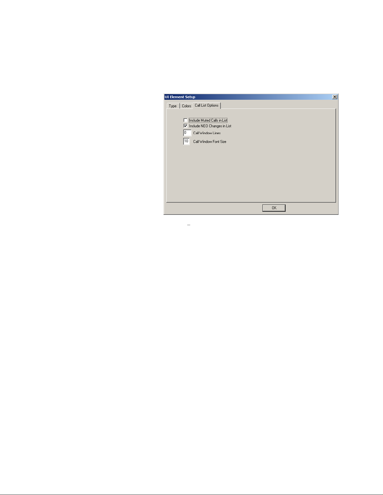
42
5.10.3.2
Another function that can be embedded into a popup window is a call list.
The call list consists of up to 500 lines of text that includes the date, time, and channel information for every
incoming radio call. If user ANI information is available, it is displayed as well. This provides the dispatcher with a
histori
in
5.10.3
located as described previously. When
editing the properties of the popup,
the UI Element Function from being Popup
Window Control to that of Popup Call
History. When the CSoftRuntime.exe
program is run, the inside of the window
will contain lines of text and a scroll bar
allowing review of up to 500 lines of radio
calls
with setup options will appear when the Call
History is selected as the popup type. The
first two options help to control how many
calls get placed into the call history list,
muted calls and NEO events can be inclu
or excluded from the call history. The third
entry allows for fewer lines to be saved in
the call history. Enter the maximum number
of lines to be kept in the call history. The
final option allows control of the font size of
the text in the Call His
Popup Call History
cal view of all the activity on the connected radio channels. To add this function, create a popup as described
. The window can be sized and
. Starting in version 2.7, a third tab
tory window. The default is 8. Enter a larger number for larger text.
change
ded
Figure 39 Call Hi
story Setup
5.10.3.2.1 Call History IRR Playback
In addition to displaying a call history, the call window can also be used for playback of the audio from recent calls.
The IRR function has previously been discussed, but an alternate way to play back a call is to double click on the
date stamped entry of the call in the call history window. If the audio was played to either the select or unselect
speaker, it will be stored and accessible. The recorder will
not played because the a previous call is being played. Three minutes of audio, is still the normal stored audio.
Silence between calls is not stored.
also continue to record other calls that come in, but are
Page 43
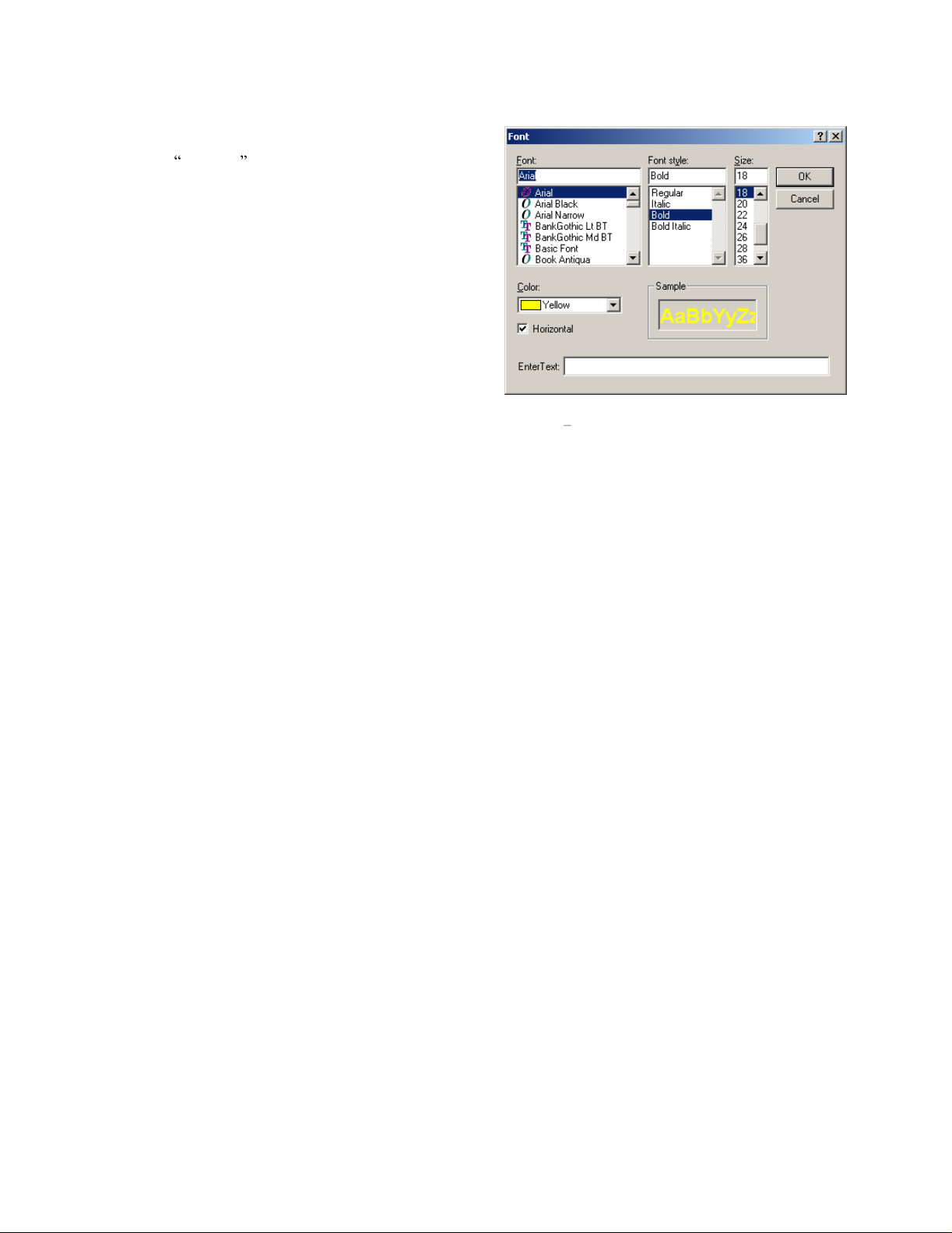
43
5.10.4 Adding Descriptive Text
Text can be added
Selecting Add Text from the Insert menu opens the dialog
box shown in
Windows text definition dialog box with a couple items
added. Generally it
like Arial and Times Roman for screen layouts. Otherwise,
the designer must make sure that the font exists on the
computer that will be used for the dispatcher.
After the dialog box opens, select the standard options of
Font, Font Style, Size, and Color. Changes to these options
will be displayed in the Sample box giving the designer an
opportunity to view the text before actually placing it.
to the main screen or a popup window.
Figure 40
. This is pretty much the standard
is a good idea to select generic fonts
The next two
package. The Horizontal checkbox is the default. If
checked the text will be placed onto the screen with a
normal left to right reading direction. Unchecking it will
place the text in a vertical orientation.
The actual text string to be placed on the screen is entered into the bottom text entry box. A text string can be up to
50 characters.
The text string will be placed onto the screen in the upper left corner. It can be moved with the mouse or the
menu/to
allow it to be dragged to a new location. Copy also works while moving the text by holding down the CTRL key.
While selected it can also have its size increased and decreased and be rotated. Upside down text is not supported.
The increase/decrease commands have the same function whether selected for width or height. Each just enlarges or
decreases the point size of the text string. Text can be
it.
Version 2.7 increased the maximum number of text strings in a design from 200 to 2000.
options are specific to the designer software
Figure 40 The Add Text dialog box
olbar options. Text shows it is selected by placing a box around the string. Clicking within that box will
edited after it is placed onto the screen by Right-Clicking on
Page 44

44
6 Basic Screen Design Tutorial
This chapter is a brief tutorial that will guide the user through the
few of the other user interface elements. From this design, other more complicated designs can be completed. It is a
good idea to periodically save the design. The final design is loaded on the CD that th
and is called Tutorial 1.veg . In the final step, the design will be saved with the default name of
C6200F_Default.veg which is the filename that CSoftRuntime.exe loads when it starts running.
6.1 First Step
In most console designs, prior knowledge of the system architecture must exist. In this case, the console is going to
be designed for a six radio system. Each radio will have four active frequencies. Start by enabling lines 2-6 in the
Multicast
Ports should be changed to start from 1072 and increase up from there. For each of lines 1-6, click on the frequency
button at the right of each l
more meaningful. Leave the Echo Packet entries turned off.
IP Setup dialog under the edit menu. The RX Port addresses are fine as defaults for this exercise. The TX
Setup Basic IP Pa
ine and enable Lines 1-4. Feel free to modify frequency and line names to something
rameters
creation of a 6 line console design along with a
is software was delivered on
Figure 41 Tutorial Line IP Setup dialog
Page 45

45
6.2 Second Step
Start by adding a button and moving it to the bottom center of the screen. Enlarge the button width by about three
times. Add two other regular buttons on either side of it. By selecting each button and editing the properties, make
the left button
should look something like
Monitor, the large middle button PTT-Main, and the right button Intercom. When you are done it
Monitor, PTT-Main, and Int
Figure 42
.
ercom
Figure 42 First Step in Tutorial. Monitor, PTT-Main, and Intercom
Page 46
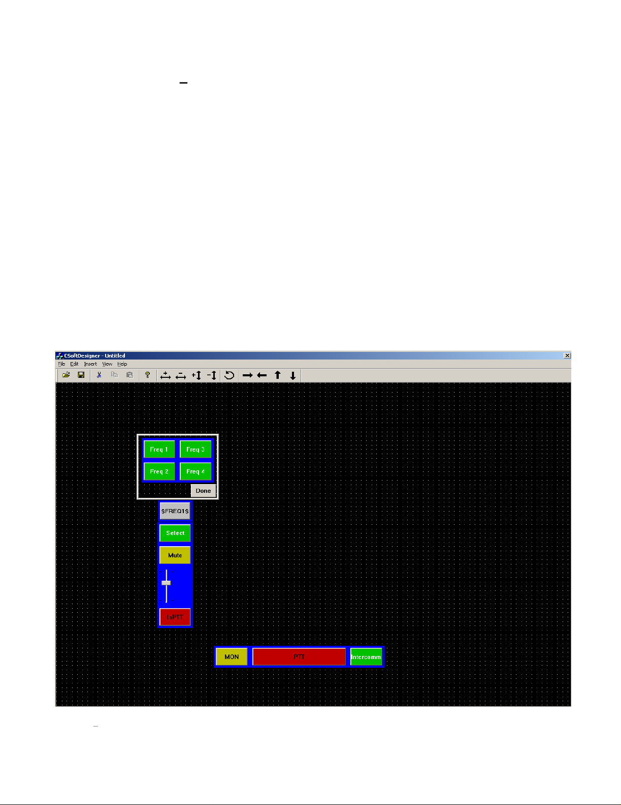
46
6.3 Step Three
1) In step three add to the left and above the Monitor button, a button. Set its type to PTT-Per Line. Leave its
line set as Line 1. The third tab will be left as selection 0:Default Frequency. Frequency contr
added later.
2) Directly above the InPTT button, add a volume control. Set it as Per Line Volume control, set for line 1,
and leave the options in the third tab at default, except to change the background color to the same color of
blue as the InP
3) Above the Volume control, add another button. Set its function to Mute-Per Line. Select Line 1 for it. The
third tab parameters should be left as default. Increase the width of the volume control to match that of the
buttons above an
4) Above the Mute button, place another button. Set its function to Select. Set it to Line 1.
5) Above the Select button, add a Popup button. In the color tab, sets its text for both the up and down
positions to be $FREQ1$. The popup button shoul
6) Open the popup window and insert four buttons. Each of these buttons should be Frequency Change
buttons. Set them all for Line 1 and set each to one of the four frequencies. Change the up and down text
to th
e F1-F4 or some other useful name. Adjust the size of the window to minimize the amount of space it
occupies on the screen.
After steps 1-6 have been completed, the screen display should look like
Create First Column of Controls
TT buttons border.
d below it.
d have its width and height decreased by one.
ol will be
Figure 43.
Figure 43
Third Step Tutorial Screen Layout
Page 47
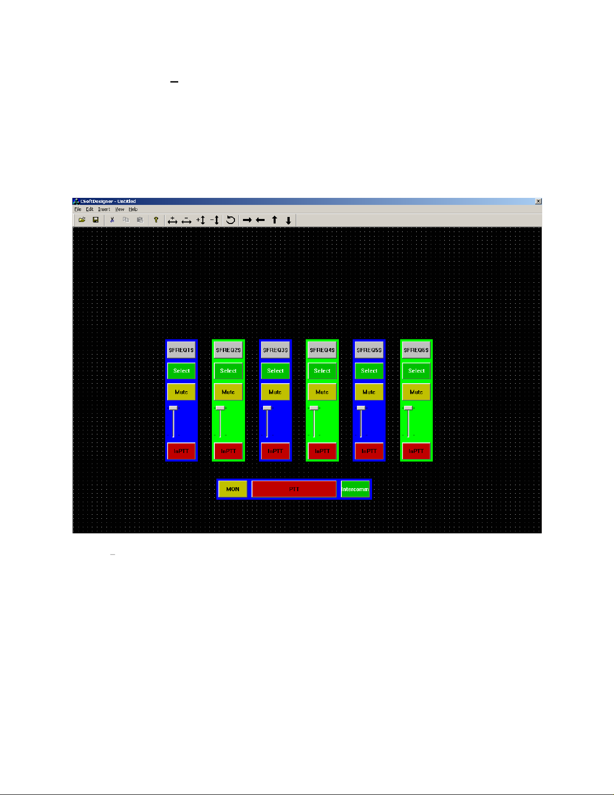
47
6.4 Step Four
In this step, the first column created will be copied across the screen to create five more channels of controls. The
quickest way to do this is to use the
to the left of the Frequency popup. While holding down the left mouse button, draw a rectangle around the column
of controls. When at the lower right of the control column, re
now be selected. Select copy from the Edit menu followed by Paste. Copies of the selected elements will be
displayed below and to the right of the old controls. They will all be selected. Use th
move them to the new location. While the group is selected, right click on one of the controls in the group. The
Properties option will appear as a shortcut menu. Selecting properties will allow changing all of the buttons line
Create Other Five Control Columns
mouse to select the entire column worth of controls. Move the mouse above and
lease the button. All controls within the rectangle will
e arrow keys on the toolbar to
Figure 44 Step Four tutorial screen. All six line controls are present
association with one selection. The Freq popup will still need to be opened and have all of its frequency selection
buttons changed. This can be done again by selecting all the buttons in the window and right clicking. In addition
change the varia
line will always be displayed within the Popup button. The border/background colors can also be changed to help
differentiate the radio channels. Repeat
look something like
ble name on the popup button itself to that of the new line. That way, the correct frequency for the
these steps for each column. When this is completed the display should
Figure 44
.
Page 48

48
6.5 Step Five
In this step, several other common controls will be added.
1) In a grouping to the left of the columns of line controls, add buttons for the following. Mute Main, TX All,
RX All, and Group Select. None of these four buttons requires any setup other th
from the Type tab of the properties dialog box. Under the group of four buttons just added, insert two Alert
keys. Set one of them to be a pulsed tone and the other to be a Hi-Lo Warble. Fill in frequencies and
durations for al
2) On the right side of the design, a 12 key DTMF keypad will be added. Start by inserting one new button,
setting it to DTMF, and then copy it with CTRL-mouse drag method to make the rest of the keypad. Then
go back and c
3) Finally, add two more volume controls. Make these volume controls horizontally oriented and assign the
left one as Volume Master Select and the right one as Volum
each slider to label its function.
After completing these three steps, the screen layout should look simila
Other Standard Con
l boxes that are not grayed out.2)
hange the DTMF digit for each key, default text will automatically be placed on the button.
trols
an to select the function
e Master Unselect. Add text above or below
r to
Figure 45
.
Figure 45 Tutorial Step 5. General controls, DTMF keypad, and Master Volumes.
Page 49

49
6.6 Step 6
Having completed steps 1-5, the design is now ready to test. Save out the design into the same directory as
CSoftRuntime.exe. Use the default filename of C6200F_Default.veg. This file w
the runtime software and activated. If the runtime program finds the file and runs correctly, the screen will look like
Figure 46
.
Testing the Design
ill then be automatically loaded by
Figure 46 Runtime displa
A number of items should be pointed out for the runtime software.
1) The top of the window has a status bar that is used to display information to the console operator. Close
observation will reveal 5 separate areas, called panes, each
left to right, these panes display: text messages, IRR playback position, PTT status, VU Meter, and the
computer s time.
2) The select button is used for a number of status functions. When transmit packets ar
console on the network, a small red LED with a T in is placed on the select button to indicate to the
operator that transmit activity is active on that line and therefore the operator cannot transmit on it. When
receive activity i
indications that appear on the Select button include a XT indication stating that transmit activity is
present on the line, but it is crossmuted, and a SUP indication to
The SUP indication also shows up on the Mute and InPTT buttons for a particular line since they are also
directly affected by the supervisor function.
y of tutorial design.
displaying different specific information. From
e present from another
s present, a small red LED with an R is placed on the Select button. Two other
show that the line/button is supervised.
Page 50

50
3) Although it is not setup to be demonstrated in this example, it
within a Popup window. Had a popup been created initially in the tutorial, and all the Select, Mute, InPtt,
Volume Controls, and Frequency Popup windows been placed into it, it would have allowed a grouping of
lines that could have been hidden from view by closing the window. This would allow for a much larger
number of lines to be controlled from the single screen user interface. It is of course likely that line activity
could occur on a line while its window
Popup button that the line is stored within. An Active LED indication will be placed onto any Popup
button that has indications occurring within it. If the dispatcher has not muted the lines within the hidden
window, audio would still be heard and the activity indication on the popup control would indicate where
the traffic was coming from.
4) Notice that the $FREQx$ text that was placed onto the Popup windows for frequency control, now
the frequency of the line. If another parallel console changes the frequency of the radio on the line, it will
be automatically updated to display the new frequency name.
5) Once a design has been completed, as in the tutorial example, all buttons s
function.
is closed. The dispatcher would receive an indication of this on the
is also possible to place the line controls
hould be checked for correct
display
Page 51

51
Appendix A. Troubleshooting
This appendix describes different ways of troubleshooting problems that may occur while using C-Soft.
Socket Warning Message
The socket warning message, shown in
specified port because Windows or another application is already using the port. To determine what port(s) and
applications(s) are causing the error, first find what port(s) CSoftRuntime was unable to access. This list is located
in SocketLog.txt and is located on the computer in the csoftruntime.exe directory. Next, determine what
applications are using the ports listed in the SocketLog.txt by opening the Windows s Command Prompt and
running NETSTAT a . The port number is located under the local address column and the application using that
port is listed under the foreign address column. The final step is to close the applications that are using the po
CSoftRuntime is unable to access. If it is not possible or desired to close the application using the port (i.e. it is a
Windows port or application that needs to be running) change the CSoftRuntime s port assignments in
CSoftDesigner as discussed in Section
Figure 47
5.3
.
Figure 47
, will appear when CSoftRuntime is unable to gain control of a
Socket Warning Dialog
rts
Page 52

52
7 Warranty, Service, Repair, and Comments
Important! Be sure the exact return address and a description of the problem or work to be
d
one are enclosed w
ith your equipment.
Warranty (Limited)
All Telex Manufactured Vega signaling products are guaranteed against malfunction due to defects in
materials and workmanship for three years, beginning at the date of original purchase. If such a
occurs, the product will be repaired or replaced (at our option) without charge during the three-year period,
if delivered to the Telex factory. Warranty does not extend to damage due to improper repairs, finish or
appearance items, or malfunct
does it extend to incidental or consequential damages. Some states do not allow the exclusion or limitation of
incidental or consequential damages, so the above limitation may not apply to you. This warranty gives the
customer specific legal rights, and there may be other rights which vary from state to state.
Factory Service Center
TELEX Communications, Inc
Vega Signaling Products
8601 East Cornhusker Highway, Lincoln, Nebrask
Phone: (800) 752
E-
mail: vega@telex.com, Web: www.vega-signaling.com
Claims
No liability will be accepted for damages directly or indirectly arising from the use of our materials or f
other causes. Our liability shall be expressly limited to replacement or repair of defective materials.
Suggestions or Comments
We d appreciate your input. Please send us your suggestions or comments concerning this manual, by fax or ethem to
:
vega@us.telex.com
-7560-
Sales, (800) 898
ion due to abuse or operation under other than the specified conditions, nor
.
a, 68507
-6723-
Tech Support, Fax: (402) 467
-3279
malfunction
rom any
mail
Visit our web site at
www.vega-signaling.com
Page 53

This document was created with Win2PDF available at http://www.win2pdf.com.
The unregistered version of Win2PDF is for evaluation or non-commercial use only.
 Loading...