

Page 1
Operating Instructions
Capacitive rod electrode for continuous
level measurement
VEGACAL 63
Probus PA
Document ID: 30028
Page 2

Contents
Contents
1 About this document
1.1 Function ........................................................................................................................... 4
1.2 Target group ..................................................................................................................... 4
1.3 Symbolism used ............................................................................................................... 4
2 For your safety
2.1 Authorised personnel ....................................................................................................... 5
2.2 Appropriate use ................................................................................................................ 5
2.3 Warning about incorrect use ............................................................................................. 5
2.4 General safety instructions ............................................................................................... 5
2.5 Safety label on the instrument .......................................................................................... 6
2.6 CE conformity ................................................................................................................... 6
2.7 Fulllment of NAMUR recommendations ......................................................................... 6
2.8 Safety instructions for Ex areas ........................................................................................ 6
2.9 Environmental instructions ............................................................................................... 6
3 Product description
3.1 Conguration .................................................................................................................... 7
3.2 Principle of operation........................................................................................................ 8
3.3 Operation ......................................................................................................................... 9
3.4 Packaging, transport and storage ................................................................................... 10
3.5 Accessories and replacement parts ............................................................................... 10
4 Mounting
4.1 General instructions ....................................................................................................... 12
4.2 Mounting instructions ..................................................................................................... 13
5 Connecting to power supply
5.1 Preparing the connection ............................................................................................... 16
5.2 Connection procedure .................................................................................................... 17
5.3 Wiring plan, single chamber housing.............................................................................. 18
5.4 Wiring plan, double chamber housing ............................................................................ 19
5.5 Wiring plan, double chamber housing Ex d .................................................................... 21
5.6 Wiring plan - version IP 66/IP 68, 1 bar ........................................................................... 23
6 Set up with the display and adjustment module PLICSCOM
6.1 Short description ............................................................................................................ 24
6.2 Insert display and adjustment module ............................................................................ 24
6.3 Adjustment system ......................................................................................................... 25
6.4 Setup steps .................................................................................................................... 26
6.5 Menu schematic ............................................................................................................. 30
6.10 Saving the parameter adjustment data ........................................................................... 32
7 Set up with PACTware and other adjustment programs
7.1 Connect the PC .............................................................................................................. 33
7.2 Parameter adjustment with PACTware ............................................................................ 34
7.3 Parameter adjustment with AMS™ and PDM ................................................................. 34
7.4 Saving the parameter adjustment data ........................................................................... 34
8 Maintenanceandfaultrectication
8.1 Maintenance .................................................................................................................. 35
8.2 Rectify faults ................................................................................................................... 35
30028-EN-130917
2
VEGACAL 63 • Probus PA
Page 3

8.3 Exchanging the electronics module ................................................................................ 37
8.4 How to proceed in case of repair .................................................................................... 37
9 Dismounting
9.1 Dismounting steps.......................................................................................................... 38
9.2 Disposal ......................................................................................................................... 38
10 Supplement
10.1 Technical data ................................................................................................................ 39
10.2 Probus PA ..................................................................................................................... 43
10.3 Dimensions .................................................................................................................... 47
Contents
30028-EN-130917
VEGACAL 63 • Probus PA
Supplementary documentation
Information:
Supplementary documents appropriate to the ordered version come
with the delivery. You can nd them listed in chapter "Product descrip-
tion".
Instructions manuals for accessories and replacement parts
Tip:
To ensure reliable setup and operation of your VEGACAL 63, we oer
accessories and replacement parts. The corresponding documenta-
tions are:
27720 - VEGADIS 61
•
30531 - Electronics module VEGACAL series 60
•
34296 - Protective cover
•
31088 - Flanges according to DIN-EN-ASME-JIS
•
Editing status: 2013-08-21
3
Page 4
1 About this document
1 About this document
1.1 Function
This operating instructions manual provides all the information you
need for mounting, connection and setup as well as important instructions for maintenance and fault rectication. Please read this information before putting the instrument into operation and keep this manual
accessible in the immediate vicinity of the device.
1.2 Target group
This operating instructions manual is directed to trained specialist
personnel. The contents of this manual should be made available to
these personnel and put into practice by them.
1.3 Symbolism used
Information, tip, note
This symbol indicates helpful additional information.
Caution: If this warning is ignored, faults or malfunctions can result.
Warning: If this warning is ignored, injury to persons and/or serious
damage to the instrument can result.
Danger: If this warning is ignored, serious injury to persons and/or
destruction of the instrument can result.
Ex applications
This symbol indicates special instructions for Ex applications.
List
•
The dot set in front indicates a list with no implied sequence.
Action
→
This arrow indicates a single action.
1 Sequence of actions
Numbers set in front indicate successive steps in a procedure.
Battery disposal
This symbol indicates special information about the disposal of batteries and accumulators.
30028-EN-130917
4
VEGACAL 63 • Probus PA
Page 5

2 For your safety
2 For your safety
2.1 Authorised personnel
All operations described in this operating instructions manual must
be carried out only by trained specialist personnel authorised by the
plant operator.
During work on and with the device the required personal protective
equipment must always be worn.
2.2 Appropriate use
VEGACAL 63 is a sensor for continuous level measurement.
You can nd detailed information on the application range in chapter
"Product description".
Operational reliability is ensured only if the instrument is properly
used according to the specications in the operating instructions
manual as well as possible supplementary instructions.
For safety and warranty reasons, any invasive work on the device
beyond that described in the operating instructions manual may be
carried out only by personnel authorised by the manufacturer. Arbitrary conversions or modications are explicitly forbidden.
2.3 Warning about incorrect use
Inappropriate or incorrect use of the instrument can give rise to
application-specic hazards, e.g. vessel overll or damage to system
components through incorrect mounting or adjustment.
30028-EN-130917
VEGACAL 63 • Probus PA
2.4 General safety instructions
This is a state-of-the-art instrument complying with all prevailing
regulations and guidelines. The instrument must only be operated in a
technically awless and reliable condition. The operator is responsible
for the trouble-free operation of the instrument.
During the entire duration of use, the user is obliged to determine the
compliance of the necessary occupational safety measures with the
current valid rules and regulations and also take note of new regula-
tions.
The safety instructions in this operating instructions manual, the national installation standards as well as the valid safety regulations and
accident prevention rules must be observed by the user.
For safety and warranty reasons, any invasive work on the device
beyond that described in the operating instructions manual may be
carried out only by personnel authorised by the manufacturer. Arbitrary conversions or modications are explicitly forbidden.
The safety approval markings and safety tips on the device must also
be observed.
5
Page 6

2 For your safety
2.5 Safety label on the instrument
The safety approval markings and safety tips on the device must be
observed.
2.6 CE conformity
This device fullls the legal requirements of the applicable EC guidelines. By attaching the CE mark, VEGA provides a conrmation of
successful testing. You can nd the CE conformity declaration in the
download area of "www.vega.com".
2.7 FulllmentofNAMURrecommendations
NAMUR is the automation technology user association in the process
industry in Germany. The published NAMUR recommendations are
accepted as the standard in eld instrumentation.
The device fullls the requirements of the following NAMUR recommendations:
NE 21 – Electromagnetic compatibility of equipment
•
NE 43 – Signal level for malfunction information from measuring
•
transducers
NE 53 – Compatibility of eld devices and display/adjustment
•
components
For further information see www.namur.de.
2.8 Safety instructions for Ex areas
Please note the Ex-specic safety information for installation and operation in Ex areas. These safety instructions are part of the operating
instructions manual and come with the Ex-approved instruments.
2.9 Environmental instructions
Protection of the environment is one of our most important duties.
That is why we have introduced an environment management system
with the goal of continuously improving company environmental protection. The environment management system is certied according
to DIN EN ISO 14001.
Please help us fulll this obligation by observing the environmental
instructions in this manual:
Chapter "Packaging, transport and storage"
•
Chapter "Disposal"
•
30028-EN-130917
6
VEGACAL 63 • Probus PA
Page 7
Scope of delivery
3 Product description
3 Product description
3.1 Conguration
The scope of delivery encompasses:
Level sensor VEGACAL 63
•
Documentation
•
– this operating instructions manual
– Operating instructions manual 27835 "Display and adjustment
module PLICSCOM" (optional)
– Supplementary instructions manual 31708 "Heating for display
and adjustment module" (optional)
– Supplementary instructions manual "Plug connector for con-
tinuously measuring sensors" (optional)
– Ex-specic "Safety instructions" (with Ex versions)
– if necessary, further certicates
Constituent parts
Type plate
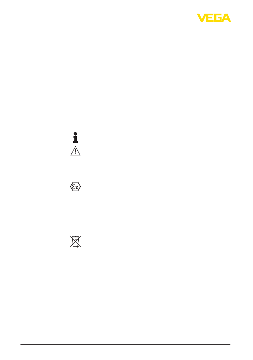
The VEGACAL 63 consists of the components:
Process tting with probe
•
Housing with electronics
•
Housing cover, optionally available with display and adjustment
•
module
1
2
3
Fig. 1: VEGACAL 63 - rod version with plastic housing
1 Housing cover with integrated display and adjustment module (optional)
2 Housing with electronics
3 Processtting
The nameplate contains the most important data for identication and
use of the instrument:
30028-EN-130917
VEGACAL 63 • Probus PA
7
Page 8

3 Product description
1
2
3
4
5
6
7
8
Fig. 2: Layout of the type label (example)
1 Instrument type
2 Product code
3 Approvals
4 Process and ambient temperature, process pressure
5 Power supply and signal output, electronics
6 Protection rating
7 Probe length
8 Order number
9 Serial number of the instrument
10 Material, wetted parts
11 Symbol of the device protection class
12 Reminder to observe the instrument documentation
13 ID numbers, instrument documentation
14 NotiedauthorityforCEmarking
15 Approval directives
15
14
13
12
11
10
9
With the serial number, you can access the delivery data of the instrument via www.vega.com, "VEGA Tools" and "serial number search".
In addition to the type label outside, you can also nd the serial number on the inside of the instrument.
Area of application
Functional principle
8
3.2 Principle of operation
VEGACAL 63 is a level sensor with fully insulated probe for continuous level measurement.
The electronics functions according to the admittance principle
(phase-selective admittance processing).
It is designed for industrial use in all areas of process technology and
can be applied in all areas of industrial process measurement.
Fully insulated probes such as VEGACAL 63 are preferably used in
conductive liquids.
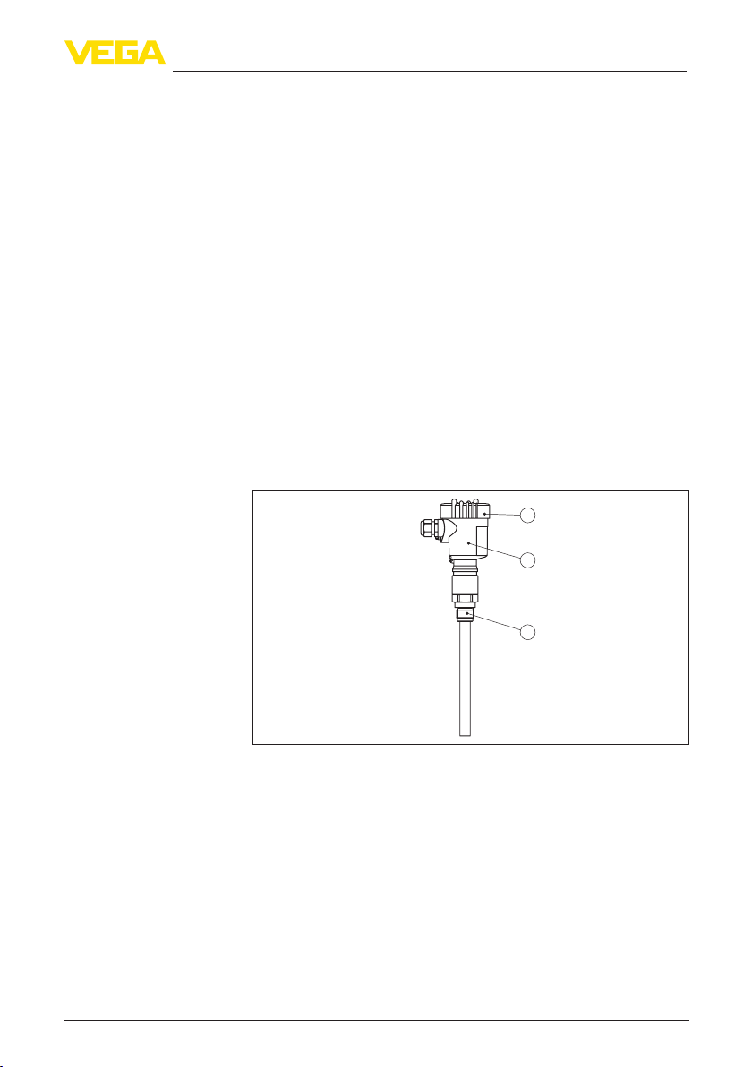
Probe, measured product and vessel wall form an electrical capacitor.
The capacitance is inuenced by three main factors.
30028-EN-130917
VEGACAL 63 • Probus PA
Page 9
3 Product description
1
2
3
Fig. 3: Functional principle - Plate capacitor
1 Distance between the electrode surfaces
2 Size of the electrode surfaces
3 Type of dielectric between the electrodes
The probe and the vessel wall are the capacitor plates. The measured
product and the insulation are the dielectric. Due to the higher dielectric constant of the insulation and the conductive product compared to
air, the capacitance increases as the probe is gradually covered.
The capacitance as well as the resistance change are converted by
the electronics module into a level-proportional signal.
Power supply and bus
communication
GSD/EDD
30028-EN-130917
VEGACAL 63 • Probus PA
Power supply via the Probus DP/PA segment coupler or VEGALOG
571 EP cards. A two-wire cable according to Probus specication
serves as carrier of both power and digital data transmission for
multiple sensors. The instrument prole of VEGACAL 63 corresponds
to prole specication version 3.0.
The backlight of the display and adjustment module is powered by the
sensor. Prerequisite is a certain level of operating voltage.
The data for power supply are specied in chapter "Technical data".
The optional heating requires its own operating voltage. You can nd
details in the supplementary instructions manual "Heating for display
and adjustment module".
This function is generally not available for approved instruments.
The GSD (instrument master les) and bitmap les necessary for
planning your Probus-DP-(PA) communication network are available
from the download section on the VEGA homepage www.vega.com
under "Services-Downloads-Software-Probus". There you can
also nd the appropriate certicates. In a PDM environment, an EDD
(Electronic Device Description) is also required to enable the full
range of sensor functions (also available as a download).A CD with
the appropriate les can be ordered via e-mail under info@de.vega.
com or by phone from one of the VEGA agencies under the order
number "DRIVER.S".
3.3 Operation
The instrument can be adjusted with the following adjustment media:
With the display and adjustment module
•
9
Page 10

3 Product description
Packaging
with the suitable VEGA DTM in conjunction with an adjustment
•
software according to the FDT/DTM standard, e.g. PACTware and
PC
with the adjustment program PDM
•
3.4 Packaging, transport and storage
Your instrument was protected by packaging during transport. Its
capacity to handle normal loads during transport is assured by a test
based on ISO 4180.
The packaging of standard instruments consists of environmentfriendly, recyclable cardboard. For special versions, PE foam or PE
foil is also used. Dispose of the packaging material via specialised
recycling companies.
Transport
Transport inspection
Storage
Storage and transport
temperature
PLICSCOM
VEGACONNECT
Transport must be carried out in due consideration of the notes on the
transport packaging. Nonobservance of these instructions can cause
damage to the device.
The delivery must be checked for completeness and possible transit
damage immediately at receipt. Ascertained transit damage or concealed defects must be appropriately dealt with.
Up to the time of installation, the packages must be left closed and
stored according to the orientation and storage markings on the
outside.
Unless otherwise indicated, the packages must be stored only under
the following conditions:
Not in the open
•
Dry and dust free
•
Not exposed to corrosive media
•
Protected against solar radiation
•
Avoiding mechanical shock and vibration
•
Storage and transport temperature see chapter "Supplement -
•
Technical data - Ambient conditions"
Relative humidity 20 … 85 %
•
3.5 Accessories and replacement parts
The display and adjustment module PLICSCOM is used for measured
value indication, adjustment and diagnosis. It can be inserted into the
sensor or the external display and adjustment unit and removed at
any time.
You can nd further information in the operating instructions "Display
and adjustment module PLICSCOM" (Document-ID 27835).
The interface adapter VEGACONNECT enables the connection of
communication-capable instruments to the USB interface of a PC. For
parameter adjustment of these instruments, the adjustment software
PACTware with VEGA-DTM is required.
30028-EN-130917
10
VEGACAL 63 • Probus PA
Page 11

3 Product description
You can nd further information in the operating instructions "Interface
adapter VEGACONNECT" (Document-ID 32628).
VEGADIS 62
Protective cap
Flanges
Screening tube adapter
VEGADIS 62 is suitable for measured value indication and adjustment
of sensors with HART protocol. It is looped into the 4 … 20 mA/HART
signal cable.
You can nd further information in the operating instructions "VE-
GADIS 62" (Document-ID 36469).
The protective cover protects the sensor housing against soiling and
intense heat from solar radiation.
You will nd additional information in the supplementary instructions
manual "Protective cover" (Document-ID 34296).
Screwed anges are available in dierent versions according to the
following standards: DIN 2501, EN 1092-1, BS 10, ANSI B 16.5,
JIS B 2210-1984, GOST 12821-80.
You can nd additional information in the supplementary instructions
manual "Flanges according to DIN-EN-ASME-JIS" (Document-ID
31088).
Condensation
In case of strong condensation, the draining of condensed water
can change the measurement accuracy. The suitable version is the
Screening against condensation. The condensation can drain o
outside on the screening tube adapter.
Typical applications of the screening tube adapters are e.g. for
condensation or sockets. Apart from the standard version, there is
a second version for vacuum with a sepcial seal. When the screening tube adapter is submerged in liquid, we recommend the use of a
vacuum-tight version.
Socket
In case of long sockets, the screening tube can increase the sensitivity of the probe by compensating the inuences of the socket. The
suitable version is Capacitive screening, vacuum-tight.
When the probe is mounted laterally, buildup can accumulate in the
socket. A screening tube makes the covered part of the probe inactive
and hence insensitive to inuence from buildup and socket. Hence,
the screening tube adapter excludes changing inuences caused by
the medium and ensures stable measurement conditions. The suitable version is Capacitive screening, vacuum-tight.
30028-EN-130917
VEGACAL 63 • Probus PA
11
Page 12
4 Mounting
Suitability for the process
conditions
4 Mounting
4.1 General instructions
Make sure that all parts of the instrument coming in direct contact
with the process, especially the sensor element, process seal and
process tting, are suitable for the existing process conditions, such
as process pressure, process temperature as well as the chemical
properties of the medium.
You can nd the specications in chapter "Technical data" and on the
nameplate.
Installation position
Welding work
Handling
Moisture
Select an installation position you can easily reach for mounting and
connecting as well as later retrotting of a display and adjustment
module. The housing can be rotated by 330° without the use of any
tools. You can also install the display and adjustment module in four
dierent positions (each displaced by 90°).
Before beginning the welding work, remove the electronics module
from the sensor. By doing this, you avoid damage to the electronics
through inductive coupling.
With threaded versions, the housing must not be used to screw in the
instrument. Applying tightening forces on the housing can damage its
internal parts.
Use the hexagon for screwing in.
Use the recommended cables (see chapter "Connecting to power
supply") and tighten the cable gland.
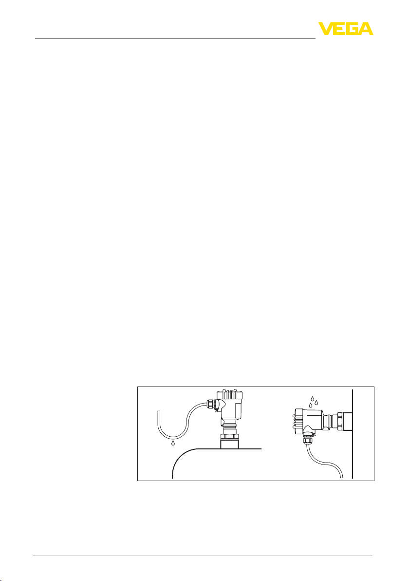
You can give your instrument additional protection against moisture
penetration by leading the connection cable downward in front of the
cable entry. Rain and condensation water can thus drain o. This applies mainly to outdoor mounting as well as installation in areas where
high humidity is expected (e.g. through cleaning processes) or on
cooled or heated vessels.
Pressure/Vacuum
12
Fig. 4: Measures against moisture penetration
The process tting must be sealed if there is gauge or low pressure in
the vessel. Before use, check if the seal material is resistant against
the measured product and the process temperature.
VEGACAL 63 • Probus PA
30028-EN-130917
Page 13

4 Mounting
The max. permissible pressure is specied in chapter "Technical
data" or on the type label of the sensor.
Insulating measures, such as e.g. covering the thread with teon tape,
can interrupt the necessary electrical connection with metal vessels.
For this reason, ground the probe on the vessel or use a conductive
seal material.
Vessel material
Vessel forms
Installation position
Metal vessel
Make sure that the mechanical connection of the probe to the vessel
is electrically conductive to ensure sucient grounding.
Use conductive seals, such as those made of copper or lead, etc.
Insulating measures, such as covering the thread with Teon tape,
can interrupt the necessary electrical connection with metal vessels.
For this reason, ground the probe on the vessel or use a conductive
seal material.
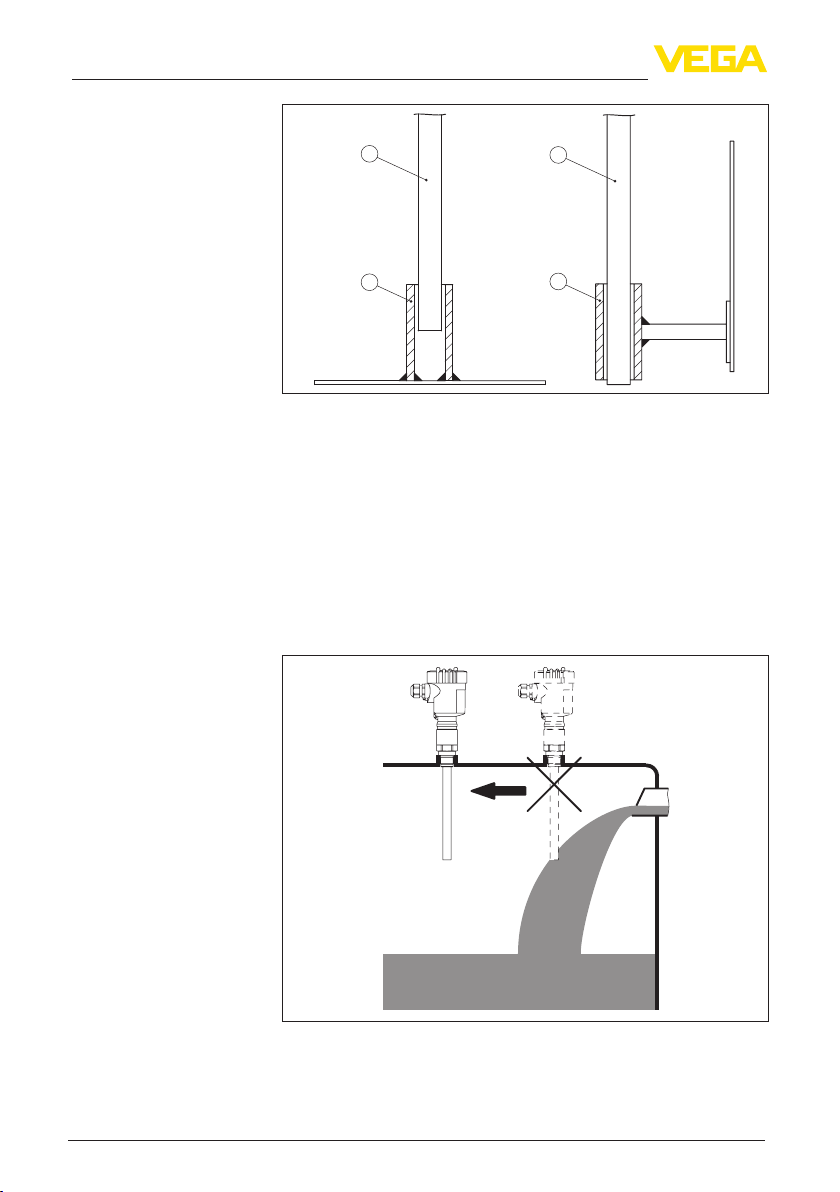
Non-conductivevessels
In non-conductive vessels, e.g. plastic tanks, the second pole of the
capacitor must be provided separately, e.g. in the form of a concentric
tube.
If possible, the capacitive probe should be mounted vertically or parallel to the counter electrode. This applies particularly to applications
in non-conductive products.
In cylindrical tanks, spherical tanks or other asymmetrical tank forms,
nonlinear level values are generated due to the varying distance to
the vessel wall.
Use a concentric tube in non-conductive products or linearize the
meas. signal.
4.2 Mounting instructions
During operation, the probe must not touch any installations or the
vessel wall. The measured value can also change if the distance to
the vessel wall changes considerably. If necessary, secure the end of
the probe (insulated).
30028-EN-130917
VEGACAL 63 • Probus PA
13
Page 14
4 Mounting
Inowingmedium
1
2
Fig. 5: Fasten the probe
1 Probe
2 Plastic socket
1
2
In vessels with conical bottom it can be advantageous to mount the
sensor in the center of the vessel, as measurement is then possible
down to the lowest point of the vessel bottom.
If the instrument is mounted in the lling stream, unwanted false
measurement signals can be generated. For this reason, mount the
instrument at a position in the vessel where no disturbances, e.g. from
lling openings, agitators, etc., can occur.
This applies particularly to instrument versions with a longer probe.
Torque with PTFE plated
anges
14
30028-EN-130917
Fig.6:Inowingmedium
To compensate the normal voltage loss due to sealing materials, you
have to additionally use disc springs for fastening ange screws on
VEGACAL 63 • Probus PA
Page 15

4 Mounting
PTFE coated anges. Tighten the screws moderately with the torque
stated in the technical data.
30028-EN-130917
VEGACAL 63 • Probus PA
15
Page 16
5 Connecting to power supply
Safety instructions
5 Connecting to power supply
5.1 Preparing the connection
Always keep in mind the following safety instructions:
Connect only in the complete absence of line voltage
•
If voltage surges are expected, overvoltage arresters should be
•
installed according to Probus specications
Tip:
We recommend VEGA overvoltage arrester B63-32.
In hazardous areas you must take note of the respective regulations,
conformity and type approval certicates of the sensors and power
supply units.
Voltage supply
Connection cable
Cablegland½NPT
Cable screening and
grounding
Power is supplied via a Probus DP/PA segment coupler or a VEGALOG 571 EP input card. The power supply range can dier depending
on the instrument version.
The data for power supply are specied in chapter "Technical data".
Connection is made with screened cable according to the Probus
specication. Power supply and digital bus signal are carried over the
same two-wire connection cable.
Use cable with round cross-section. A cable outer diameter of
5 … 9 mm (0.2 … 0.35 in) ensures the seal eect of the cable gland.
If you are using cable with a dierent diameter or cross-section,
exchange the seal or use a suitable cable gland.
Please make sure that your installation is carried out according to the
Probus specication. In particular, make sure that the termination of
the bus is done with appropriate terminating resistors.
On the instrument with cable entry ½ NPT and plastic housing there is
a metallic ½" threaded insert moulded into the plastic housing.
Caution:
No grease should be used when screwing the NPT cable gland or
steel tube into the threaded insert. Standard grease can contain
additives that corrode the connection between threaded insert and
housing. This would inuence the stability of the connection and the
tightness of the housing.
With systems with potential equalisation, connect the cable screen
directly to ground potential at the power supply unit, in the connection
box and at the sensor. The screen in the sensor must be connected
directly to the internal ground terminal. The ground terminal outside
on the housing must be connected to the potential equalisation (low
impedance).
In systems without potential equalisation, connect the cable screen
directly to ground potential at the power supply unit and at the sensor.
In the connection box or T-distributor, the screen of the short stub to
the sensor must not be connected to ground potential or to another
cable screen. The cable screens to the power supply unit and to the
30028-EN-130917
16
VEGACAL 63 • Probus PA
Page 17

5 Connecting to power supply
next distributor must be connected to each other and also connected
to ground potential via a ceramic capacitor (e.g. 1 nF, 1500 V). The
low frequency potential equalisation currents are thus suppressed,
but the protective eect against high frequency interference signals
remains.
The total capacitance of the cable and of all capacitors must not
exceed 10 nF in Ex applications.
Take note of the corresponding installation regulations for Ex applica-
tions. In particular, make sure that no potential equalisation currents
ow over the cable screen. In case of grounding on both sides this
can be achieved by the use of a capacitor or a separate potential
equalisation.
5.2 Connection procedure
Proceed as follows:
1. Unscrew the housing cover
2. If a display and adjustment module is installed, remove it by turning it to the left.
3. Loosen compression nut of the cable entry
4. Remove approx. 10 cm (4 in) of the cable mantle, strip approx.
1 cm (0.4 in) of insulation from the ends of the individual wires
5. Insert the cable into the sensor through the cable entry
6. Lift the opening levers of the terminals with a screwdriver (see
following illustration)
7. Insert the wire ends into the open terminals according to the wiring plan
30028-EN-130917
VEGACAL 63 • Probus PA
Fig. 7: Connection steps 6 and 7
8. Press down the opening levers of the terminals, you will hear the
terminal spring closing
9. Check the hold of the wires in the terminals by lightly pulling on
them
17
Page 18

5 Connecting to power supply
Housing overview
10. Connect the screen to the internal ground terminal, connect the
outer ground terminal to potential equalisation
11. Tighten the compression nut of the cable entry. The seal ring must
completely encircle the cable
12. Screw the housing cover back on
The electrical connection is hence nished.
5.3 Wiring plan, single chamber housing
The following illustrations apply to the non-Ex as well as to the Ex-ia
version.
5
1 2
5
5
3
5
4
Fig. 8: Material versions, single chamber housing
1 Plastic
2 Aluminium
3 Stainless steel, investment casting
4 Stainless steel, electro-polished
5 Filter element for air pressure compensation of all material versions. Blind
plug with version IP 66/IP 68, 1 bar for Aluminium and stainless steel
18
30028-EN-130917
VEGACAL 63 • Probus PA
Page 19

Electronics and connection compartment
5 Connecting to power supply
Display
I²C
1
Wiring plan
4
12 5678
2
3
Fig. 9: Electronics and connection compartment, single chamber housing
1 Plug connector for VEGACONNECT (I²C interface)
2 Spring-loaded terminals for connection of the external indication VEGADIS
61
3 Ground terminal for connection of the cable screen
4 Spring-loaded terminals for voltage supply
Display
12 5 678
I2C
1
Fig. 10: Wiring plan, single chamber housing
1 Voltage supply, signal output
5.4 Wiring plan, double chamber housing
The following illustration apply to non-Ex as well as Ex ia versions.
The Exd version is described in the next subchapter.
30028-EN-130917
VEGACAL 63 • Probus PA
19
Page 20

5 Connecting to power supply
Housing overview
1 2 3
Electronics compartment
4
Fig. 11: Double chamber housing
1 Housing cover, connection compartment
2 Blind plug or plug M12 x 1 for VEGADIS 61 (optional)
3 Housing cover, electronics compartment
4 Filter element for air pressure compensation
5 Cable gland
Display
I2C
12 5678
3
Fig. 12: Electronics compartment, double chamber housing
1 Plug connector for VEGACONNECT (I²C interface)
2 Internal connection cable to the connection compartment
3 Terminals for VEGADIS 61
5
1
2
20
30028-EN-130917
VEGACAL 63 • Probus PA
Page 21

Connection compartment
5 Connecting to power supply
Wiring plan
Display
1
12
Fig. 13: Connection compartment, double chamber housing
1 Spring-loaded terminals for voltage supply
2 Plug connector for VEGACONNECT (I²C interface)
3 Ground terminal for connection of the cable screen
12
I2C
I2C
1
Fig. 14: Wiring plan, double chamber housing
1 Voltage supply, signal output
2
3
Housing overview
30028-EN-130917
VEGACAL 63 • Probus PA
5.5 Wiring plan, double chamber housing Ex d
1 2 3
4
Fig. 15: Double chamber housing
1 Housing cover, connection compartment
2 Blind plug or plug M12 x 1 for VEGADIS 61 (optional)
3 Housing cover, electronics compartment
4 Filter element for air pressure compensation
5 Cable gland
5
21
Page 22

5 Connecting to power supply
Electronics compartment
Connection compartment
Display
I2C
12 5678
3
Fig. 16: Electronics compartment, double chamber housing
1 Plug connector for VEGACONNECT (I²C interface)
2 Internal connection cable to the connection compartment
3 Terminals for VEGADIS 61
1
12
1
2
22
2
Fig. 17: Connection compartment, Ex-d double chamber housing
1 Spring-loaded terminals for power supply and cable screen
2 Ground terminal for connection of the cable screen
30028-EN-130917
VEGACAL 63 • Probus PA
Page 23

Wiring plan
Wire assignment, connection cable
5 Connecting to power supply
12
1
Fig. 18: Wiring plan, Ex-d double chamber housing
1 Voltage supply, signal output
5.6 Wiring plan - version IP 66/IP 68, 1 bar
1
2
Fig. 19: Wire assignment, connection cable
1 brown (+) and blue (-) to power supply or to the processing system
2 Shielding
30028-EN-130917
VEGACAL 63 • Probus PA
23
Page 24

6 Set up with the display and adjustment module PLICSCOM
6 Set up with the display and adjustment
module PLICSCOM
6.1 Short description
Function/Conguration
Mount/Dismount display
and adjustment module
The display and adjustment module is used for measured value
display, adjustment and diagnosis. It can be mounted in the following
housing versions and instruments:
All sensors of the plics® instrument family, in the single as well as
•
in the double chamber housing (optionally in the electronics or
connection compartment)
External display and adjustment unit VEGADIS 61
•
From a hardware version …- 01 or higher of PLICSCOM as well as a
hardware version …- 01, 03 or higher of the corresponding sensor, an
integrated backlight can be switched on via the adjustment menu. The
hardware version is stated on the type label of the PLICSCOM or the
sensor electronics.
Note:
You can nd detailed information on the adjustment in the operating
instructions manual "Display and adjustment module".
6.2 Insert display and adjustment module
The display and adjustment module can be inserted into the sensor
and removed again at any time. It is not necessary to interrupt the
power supply.
Proceed as follows:
1. Unscrew the housing cover
2. Place the display and adjustment module in the desired position
on the electronics (you can choose any one of four dierent positions - each displaced by 90°)
3. Press the display and adjustment module onto the electronics
and turn it to the right until it snaps in.
4. Screw housing cover with inspection window tightly back on
Removal is carried out in reverse order.
The display and adjustment module is powered by the sensor, an ad-
ditional connection is not necessary.
24
30028-EN-130917
VEGACAL 63 • Probus PA
Page 25

6 Set up with the display and adjustment module PLICSCOM
Fig. 20: Insert display and adjustment module
Note:
If you intend to retrot the instrument with a display and adjustment
module for continuous measured value indication, a higher cover with
an inspection glass is required.
6.3 Adjustment system
Key functions
30028-EN-130917
VEGACAL 63 • Probus PA
1
Fig. 21: Display and adjustment elements
1 LC display
2 Indication of the menu item number
3 Adjustment keys
[OK] key:
•
– Move to the menu overview
– Conrm selected menu
– Edit parameter
2
1.1
3
25
Page 26

6 Set up with the display and adjustment module PLICSCOM
– Save value
[->] key to select:
•
– Menu change
– Select list entry
– Select editing position
[+] key:
•
– Change value of the parameter
[ESC] key:
•
– Interrupt input
– Jump to next higher menu
Adjustment system
Switch-on phase
Address setting
Parameter adjustment
The sensor is adjusted via the four keys of the display and adjust-
ment module. The LC display indicates the individual menu items. The
functions of the individual keys are shown in the above illustration.
Approx. 10 minutes after the last pressing of a key, an automatic reset
to measured value indication is triggered. Any values not conrmed
with [OK] will not be saved.
6.4 Setup steps
After VEGACAL 63 is connected to voltage supply or after voltage
recurrence, the instrument carries out a self-check for approx. 30
seconds. The following steps are carried out:
Internal check of the electronics
•
Indication of the instrument type, the rmware as well as the sen-
•
sor TAGs (sensor designation)
Status byte goes briey to fault value
•
Then the current measured value will be displayed and the corresponding digital output signal will be outputted to the cable.
Before starting the actual parameter adjustment of a Probus PA
sensor, the address setting must rst be carried out. You will nd a
detailed description in the operating instructions manual of the display
and adjustment module or in the online help of PACTware or DTM.
VEGACAL 63 measures the capacitance of the respective product. To
display the actual level of the product, an allocation of the measured
capacitance to the percentage height must be carried out. For this
adjustment, the capacitance is entered with emptied and lled vessel.
If the vessel cannot be emptied or lled completely, you can carry out
the adjustment also with two known levels - for example with 10 %
and 90 %. The dierence between the empty and full adjustment
values should be as large as possible.
The actual level can then be calculated on the basis of these settings.
VEGACAL 63 must be installed. A change of level is necessary for
this adjustment.
1)
30028-EN-130917
26
1)
The values correspond to the actual measured level as well as to the settings
already carried out, e.g. default setting.
VEGACAL 63 • Probus PA
Page 27

6 Set up with the display and adjustment module PLICSCOM
In the main menu item "Basic adjustment", the individual submenu
items should be selected one after the other and provided with the
correct parameter values.
Tip:
If the display and adjustment module remains on the probe as a
display, we recommend saving the sensor data in the display and
adjustment module.
Use the function "Copy sensor data".
Start your parameter adjustment with the following menu items of the
basic adjustment:
Carry out min. adjustment
To be on the safe side, note the adjustment values for full and empty.
If an adjustment procedure fails, it is not necessary to again carry out
a level change.
These values can be helpful if the electronics has to be exchanged.
% Value
Empty adjustment
Full adjustment
Tab. 1: Adjustment protocol
Tip:
For min. adjustment the vessel should be as empty as possible, and
for max. adjustment, as full as possible. If the vessel is already full,
start with max. adjustment.
Note:
If possible, the vessel should be as empty as possible for min. adjustment.
Proceed as follows:
1. Move from the measured value display to the main menu by
pushing [OK].
Basic adjustment
▶
Display
Diagnostics
Service
Info
2. Select the menu item "Basic adjustment" with [->] and conrm
with [OK]. Now the menu item "Min. adjustment" is displayed.
Min. adjustment
0.00 %
=
0.0 pF
54.5 pF
3. Prepare the adjustment value for editing with [OK]. Move to the
selection window with [OK].
30028-EN-130917
VEGACAL 63 • Probus PA
27
Page 28

6 Set up with the display and adjustment module PLICSCOM
Min. adjustment
Accept current measured
value?
Accept?
Edit?
4. Accept the current measured value or move to the editing window
with "Edit". To edit, set the cursor to the requested position with
[->]. Set the requested % value with [+] and save with [OK]. The
cursor jumps to the capacitance value.
5. Enter the current capacitance value in pF (displayed below) for
the empty vessel corresponding to the percentage value.
6. Save the settings with [OK] and move to "Max. adjustment" with
[->].
Carry out max. adjustment
Damping
Fill the vessel to the highest possible level.
Note:
For max. adjustment, the vessel should be as full as possible. This will
make the calibration more accurate.
Proceed as follows:
Max. adjustment
100.00 %
=
1000 pF
327.4 pF
1. Prepare the adjustment value for editing with [OK]. Move to the
selection window with [OK].
Min. adjustment
Accept current measured
value?
Accept?
Edit?
2. Accept the current measured value or move to the editing window
with "Edit". To edit, set the cursor to the requested position with
[->]. Set the requested % value with [+] and save with [OK]. The
cursor jumps to the capacitance value.
3. Enter the current capacitance value in pF (displayed below) for
the full vessel corresponding to the percentage value.
4. Save the settings with [OK].
To suppress uctuations in the measured value display, e. g. caused
by an agitated product surface, a damping can be set. This time can
be between 0 and 999 seconds. Keep in mind that the reaction time of
the entire measurement will then be longer and the sensor will react
to measured value changes with a delay. In general, a period of a few
seconds is sucient to smooth the measured value display.
Damping
0 s
30028-EN-130917
28
VEGACAL 63 • Probus PA
Page 29

6 Set up with the display and adjustment module PLICSCOM
Enter the requested parameters via the appropriate keys, save your
settings and jump to the next menu item with the [->] key.
Linearization curve
Sensor-TAG
A linearisation is necessary for all vessels in which the vessel volume
does not increase linearly with the level - e.g. in a horizontal cylindrical or spherical tank - and the indication or output of the volume is
required. Corresponding linearisation curves are preprogrammed for
these vessels. They represent the correlation between the level percentage and vessel volume. By activating the appropriate curve, the
volume percentage of the vessel is displayed correctly. If the volume
should not be displayed in percent but e.g. in l or kg, a scaling can be
also set in the menu item "Display".
Linearization curve
Linear
Enter the requested parameters via the appropriate keys, save your
settings and jump to the next menu item with the [->] key.
Caution:
Note the following if the VEGACAL 63 with corresponding approval is
used as part of an overll protection system according to WHG (Water
Resources Act):
If a linearization curve is selected, the measuring signal is no longer
necessarily linear to the lling height. This must be considered by the
user especially when adjusting the switching point on the limit signal
transmitter.
In this menu item you can enter an unambiguous designation for the
sensor, e.g. the measurement loop name or the tank or product designation. In digital systems and in the documentation of larger plants,
a singular designation should be entered for exact identication of
individual measuring points.
Sensor-TAG
Sensor
Optional settings
Reset
30028-EN-130917
VEGACAL 63 • Probus PA
With this menu item, the Basic adjustment is nished and you can
now jump to the main menu with the [ESC] key.
Additional adjustment and diagnosis options such as e.g. scaling,
simulation or trend curve presentation are shown in the following
menu schematic. You will nd a detailed description of these menu
items in the operating instructions manual "Display and adjustment
module".
Basic adjustment
If the function "Reset" is carried out, the sensor resets all settings to
default.
The following values will be reset:
29
Page 30

6 Set up with the display and adjustment module PLICSCOM
Function Resetvalue
Max. adjustment 3000 pF
Min. adjustment 0 pF
Damping ti 0 s
Linearization Linear
Sensor-TAG Sensor
Display PA-Out 1
Channel (PV) lin %
Additional PA value (PV) lin %
Out-Scale-Unit %
PV Out-Scale 0.00 lin-% = 0.0 %
Information:
All additional settings are reset to the standard values of the Probus
PA specication.
Special parameters
All special parameters are reset to delivery status.
Peak value
The min. and max. values are reset to the actual value.
6.5 Menu schematic
Basic adjustment
Basic adjustment 1
▶
Display
Diagnostics
Service
Info
100.0 lin-% = 100 %
Sensor address 1.1
000
Channel 1.5
PV lin. value
30
Min. adjustment 1.2
0.00 %
=
0.0 pF
82.5 pF
Damping 1.6
0 s
Max. adjustment 1.3
100.00 %
=
1000.0 pF
327.4 pF
Sensor-TAG 1.7
Sensor
Linearization curve 1.4
Linear
30028-EN-130917
VEGACAL 63 • Probus PA
Page 31

Display
Basic adjustment 2
Display
▶
Diagnostics
Service
Info
6 Set up with the display and adjustment module PLICSCOM
Displayed value 2.1
Primary Value
Diagnostics
Basic adjustment 3
Display
Diagnostics
▶
Service
Info
Peak value 3.1
Capacit. min.: 65.7 pF
Capacit. max.: 782.4 pF
Service
Basic adjustment 4
Display
Diagnostics
Service
▶
Info
Additional PA value 4.1
Secondary Value 1
Backlight 2.4
Switchedo
Sensor status 3.2
OK
Out-Scale-Unit 4.2
▼
Volume
hl
Trend recording 3.3
Presentation of the trend
curve
PV-Out-Scale Min. 4.3
0 % = 5.0 hl
100 % = 5000.0 hl
Simulation 4.4
Start simulation?
Reset 4.5
Select reset?
30028-EN-130917
VEGACAL 63 • Probus PA
Language 4.6
German
Copy sensor data 4.7
Copy sensor data?
PIN 4.8
Enable?
31
Page 32

6 Set up with the display and adjustment module PLICSCOM
Info
Basic adjustment 5
Display
Diagnostics
Service
Info
▶
Instrument type 5.1
VEGACAL 6x
Serial number
12345678
Date of manufacture 5.2
06. February 2012
Software version
1.30
Last change using PC 5.3
05. March 2012
Sensor characteristics 5.4
Display now?
6.10 Saving the parameter adjustment data
We recommended noting the adjusted data, e.g. in this operating
instructions manual, and archiving them afterwards. They are thus
available for multiple use or service purposes.
If VEGACAL 63 is equipped with a display and adjustment module,
the most important data can be read out of the sensor into the display
and adjustment module. The procedure is described in the operating
instructions manual "Display and adjustment module" in the menu
item "Copy sensor data". The data remain there permanently even if
the sensor power supply fails.
If it is necessary to exchange the sensor, the display and adjustment
module is inserted into the replacement instrument and the data are
written into the sensor under the menu item "Copy sensor data".
32
30028-EN-130917
VEGACAL 63 • Probus PA
Page 33

7 Set up with PACTware and other adjustment programs
7 Set up with PACTware and other
adjustment programs
7.1 Connect the PC
VEGACONNECTdirectly
on the sensor
VEGACONNECTexternally
2
1
3
Fig. 22: Connection of the PC via VEGACONNECT directly to the sensor
1 USB cable to the PC
2 VEGACONNECT
3 Sensor
1
2
TWIST
LOCK
OPEN
3
4
USB
30028-EN-130917
VEGACAL 63 • Probus PA
Fig. 23: Connection via VEGACONNECT externally
1 I²C bus (com.) interface on the sensor
2 I²C connection cable of VEGACONNECT
3 VEGACONNECT
4 USB cable to the PC
Necessary components:
VEGACAL 63
•
PC with PACTware and suitable VEGA DTM
•
VEGACONNECT
•
Power supply unit or processing system
•
33
Page 34

7 Set up with PACTware and other adjustment programs
7.2 Parameter adjustment with PACTware
Further setup steps are described in the operating instructions
manual "DTM Collection/PACTware" attached to each CD and which
can also be downloaded from our homepage. A detailed description
is available in the online help of PACTware and the VEGA DTMs.
Note:
Keep in mind that for setup of VEGACAL 63, DTM-Collection in the
actual version must be used.
All currently available VEGA DTMs are included as a DTM Collection
on a CD. They can be purchased for a token fee from the responsible
VEGA agency. In addition, the actual PACTware version is also available on this CD.
In addition, this DTM Collection incl. the basic version of PACTware can be downloaded free of charge from the Internet. Move via
www.vega.com and "Downloads" to "Software".
7.3 Parameter adjustment with AMS™ and PDM
For VEGA sensors, instrument descriptions for the adjustment
programs AMS™ and PDM are available as DD or EDD. The instrument descriptions are already implemented in the current versions of
AMS™ and PDM.
For older versions of AMS™ and PDM, a free-of-charge download is
available via Internet. Move via www.vega.com and "Downloads" to
"Software".
7.4 Saving the parameter adjustment data
It is recommended to document or save the parameter adjustment
data. That way they are available for multiple use or service purposes.
The VEGA DTM Collection and PACTware in the licensed, professional version provide suitable tools for systematic project documentation
and storage.
34
30028-EN-130917
VEGACAL 63 • Probus PA
Page 35

Reactionwhenmalfunctions occur
8 Maintenance and fault rectication
8 Maintenanceandfaultrectication
8.1 Maintenance
If the instrument is used properly, no special maintenance is required
in normal operation.
8.2 Rectifyfaults
The operator of the system is responsible for taking suitable meas-
ures to rectify faults.
Failure reasons
Faultrectication
Faultrectication
CheckingProbusPA
VEGACAL 63 oers maximum reliability. Nevertheless, faults can oc-
cur during operation. These may be caused by the following, e.g.:
Sensor
•
Process
•
Voltage supply
•
Signal processing
•
The rst measures to be taken are to check the output signals as well
as to evaluate the error messages via the display and adjustment
module. The procedure is described below. Further comprehensive
diagnostics can be carried out on a PC with the software PACTware
and the suitable DTM. In many cases, the causes can be determined
and the faults rectied this way.
The following table describes possible errors and helps to remove
them:
Error Cause Rectication
When an additional instrument
is connected, the
segment fails.
Wrong pres-
entation of the
measured value in
Simatic S5
In Simatic S7 the
measured value
is always presented as 0
Max. supply
current of the segment coupler
exceeded
Simatic S5 cannot
interpret the num-
ber format IEEE
of the measured
value
Only four bytes
are consistently
loaded in the PLC
Measure the current consumption, reduce size of segment
Insert converting component from Sie-
mens
Use function component SFC 14 to
load 5 bytes consistently
30028-EN-130917
VEGACAL 63 • Probus PA
35
Page 36

8 Maintenance and fault rectication
Error Cause Rectication
Measured value on the display
and adjustment
module does not
correspond to the
value in the PLC
No connection between PLC and
PA network
Instrument does
not appear during
connection setup
In Ex applications, the regulations for the wiring of intrinsically safe
circuits must be observed.
Error messages via the
display and adjustment
module
Error Cause Rectication
E013 no measured val-
E017 Adjustment span
E036 no operable sen-
E113 Communication
The menu item
"Display - Display
value" is not set to
"PA-Out"
Incorrect adjustment of the bus
parameter and the
segment couplerdependent baud
rate
Probus DP cable
pole-reversed
Incorrect termination
Instrument not
connected to the
segment, double
assignment of an
address
ue available
Shortcircuit in the
probe, e.g. because of moisture
in the housing
too small
sor software
conict
Check values and correct, if neces-
sary
Check data and correct, if necessary
Check cable and correct, if necessary
Check termination at the beginning
and end points of the bus and terminate, if necessary, according to the
specication
Check and correct, if necessary
– Probe insulation damaged, short-
circuit due to permeating, conductive medium
– Exchange the instrument or send it
in for repair
– Remove the electronics module out
of the probe and check the resistor
between the two marked plug connections according to the gure in
paragraph "Check the resistance in
the probe".
– There should be no contact
between any of the connections
(high resistance)
– If there is still a connection -
exchange the instrument or return
it for repair
Carry out a fresh adjustment and increase the distance between min. and
max. adjustment
Carry out a software update or send
instrument for repair
Exchange the instrument or send it in
for repair
30028-EN-130917
36
VEGACAL 63 • Probus PA
Page 37

8 Maintenance and fault rectication
Reactionafterfaultrectication
Sensor serial number
Assignment
Depending on the reason for the fault and the measures taken, the
steps described in chapter "Set up" may have to be carried out again.
8.3 Exchanging the electronics module
If the electronics module is defective, it can be replaced by the user.
In Ex applications only one instrument and one electronics module
with respective Ex approval may be used.
If there is no electronics module available on site, one can be ordered
from the VEGA agency serving you.
The new electronics module must be loaded with the order data of the
sensor. These are the options:
At the factory by VEGA
•
Or on site by the user
•
In both cases, the sensor serial number is needed. The serial numbers are stated on the type label of the instrument or on the delivery
note.
Information:
When loading on site, rst of all the order data must be downloaded
from the Internet (see operating instructions manual "Electronics
module").
The electronics modules are adapted to the respective sensor and
dier in their signal output or in their power supply. You can nd a suitable electronics module in the following overview.
The oscillators dier only in their signal output and are suitable for all
series 60 sensors.
The following types are available:
CL-E60H (4 … 20 mA/HART)
•
CL-E60P (Probus PA)
•
CL-E60F (Foundation Fieldbus)
•
In Ex applications only an electronics module with respective Ex approval may be used.
30028-EN-130917
VEGACAL 63 • Probus PA
8.4 How to proceed in case of repair
You can nd a repair form as well as detailed information on how to
proceed under www.vega.com/downloads and "Formsandcerti-
cates".
By doing this you help us carry out the repair quickly and without having to call back for needed information.
If a repair is necessary, please proceed as follows:
Print and ll out one form per instrument
•
Clean the instrument and pack it damage-proof
•
Attach the completed form and, if need be, also a safety data
•
sheet outside on the packaging
Please contact for the return shipment the agency serving you. You
•
can nd the agency on our home page www.vega.com.
37
Page 38

9 Dismounting
9 Dismounting
9.1 Dismounting steps
Warning:
Before dismounting, be aware of dangerous process conditions such
as e.g. pressure in the vessel or pipeline, high temperatures, corrosive or toxic products etc.
Take note of chapters "Mounting" and "Connecting to power supply"
and carry out the listed steps in reverse order.
9.2 Disposal
The instrument consists of materials which can be recycled by specialised recycling companies. We use recyclable materials and have
designed the parts to be easily separable.
WEEE directive 2002/96/EG
This instrument is not subject to the WEEE directive 2002/96/EG and
the respective national laws. Pass the instrument directly on to a specialised recycling company and do not use the municipal collecting
points. These may be used only for privately used products according
to the WEEE directive.
Correct disposal avoids negative eects on humans and the environment and ensures recycling of useful raw materials.
Materials: see chapter "Technical data"
If you have no way to dispose of the old instrument properly, please
contact us concerning return and disposal.
38
30028-EN-130917
VEGACAL 63 • Probus PA
Page 39

10 Supplement
10 Supplement
10.1 Technical data
General data
Material 316L corresponds to 1.4404 or 1.4435
Materials, wetted parts
Ʋ Process tting - thread 316L
Ʋ Process tting - ange 316L
Ʋ Process seal Klingersil C-4400
Ʋ insulation (fully insulated) PTFE, PE
Ʋ Probe (rod fully insulated:
ø 12 mm/0.472 in)
Ʋ Probe (rod fully insulated:
ø 16 mm/0.63 in)
Materials, non-wetted parts
Ʋ Plastic housing plastic PBT (Polyester)
Ʋ Aluminium die-casting housing Aluminium die-casting AlSi10Mg, powder-coated - basis:
Ʋ Stainless steel housing - precision
casting
Ʋ Stainless steel housing, electropol-
ished
Ʋ Seal between housing and housing
cover
Ʋ Ground terminal 316L
Process ttings
Ʋ Pipe thread, cylindrical (DIN 3852-A) G½ A, G¾ A, G1 A, G1½ A
Ʋ American pipe thread, conical
(ASME B1.20.1)
Ʋ Flanges DIN from DN 25, ANSI from 1"
Weight
Ʋ Instrument weight (depending on
process tting)
Ʋ Rod weight: ø 10 mm (0.394 in) 400 g/m (4 oz/ft)
Ʋ Rod weight: ø 16 mm (0.63 in) 1100 g/m (12 oz/ft)
Sensor length (L)
Ʋ Process tting: thread and anges 0.1 … 6 m (0.328 … 19.69 ft)
Ʋ Process tting: Flanges - PTFE plated 0.15 … 6 m (0.492 … 19.69 ft)
Max. lateral lod - rod: ø 10 mm (0.394 in) 10 Nm (7.4 lbf ft)
Max. lateral load - rod: ø 16 mm (0.63 in) 10 Nm (7.4 lbf ft)
Torque of the ange screws (min.) 60 Nm (44.25 lbf ft)
316L
316L
Polyester
316L
316L
NBR (stainless steel housing, precision casting), silicone
(aluminium/plastic housing; stainless steel housing,
electropolished)
½ NPT, ¾ NPT, 1 NPT, 1½ NPT
0.8 … 4 kg (0.18 … 8.82 lbs)
30028-EN-130917
VEGACAL 63 • Probus PA
39
Page 40

10 Supplement
Max. torque (process tting - thread) -
100 Nm (73 lbf ft)
rod: ø 10 mm (0.394 in)
Max. torque (process tting - thread) -
100 Nm (73 lbf ft)
rod: ø 16 mm (0.63 in)
Output variable
Output signal digital output signal, format according to IEEE-754
Sensor address 126 (default setting)
Current value 10 mA, ±0.5 mA
Damping (63 % of the input variable) 0 … 999 s, adjustable
Input variable
Measured variable Level of liquids
Measuring principle phase-selective admittance processing (PSA)
Measuring range 0 … 3000 pF
Measuring frequency 270 kHz
Accuracy(accordingtoDINEN60770-1)
Reference conditions according to DIN EN 61298-1
Ʋ Temperature +18 … +30 °C (+64 … +86 °F)
Ʋ Relative humidity 45 … 75 %
Ʋ Air pressure 860 … 1060 mbar/86 … 106 kPa (12.5 … 15.4 psig)
Temperature error
Ʋ < 120 pF < 1 pF
Ʋ > 120 pF 1 % of the current measured value
Linearity error < 0.25 % of the complete measuring range
Ambient conditions
Ambient, storage and transport tempera-
-40 … +80 °C (-40 … +176 °F)
ture
Process conditions
Process pressure
Ʋ Threaded versions -1 … 64 bar/-100 … 6400 kPa (-14.5 … 928 psig), de-
pending on the process tting
Ʋ Flange version -1 … 64 bar/-100 … 6400 kPa (-14.5 … 928 psig), de-
pending on the process tting
Ʋ Flange version ≥ 3"/DN 80, plated -0.4 … 64 bar/-40 … 6400 kPa (-5.8 … 928 psig), de-
pending on the process tting
Process temperature VEGACAL 63 of 316L
Ʋ Insulation PE -40 … +80 °C (-40 … +176 °F)
Ʋ Insulation PTFE -50 … +150 °C (-58 … +302 °F)
40
VEGACAL 63 • Probus PA
30028-EN-130917
Page 41

10 Supplement
Process temperature (thread or ange
-50 … +200 °C (-58 … +392 °F)
temperature) with temperature adapter
(option with PTFE)
2
80°C
(176°F)
40°C
(104°F)
0°C
(32°F)
-50°C
(-58°F)
-40°C
(-40°F)
Fig. 24: Ambient temperature - Process temperature
1 Process temperature
2 Ambient temperature
3 Temperature range with temperature adapter
(122°F)
50°C
100°C
(212°F)
150°C
(302°F)
3
200°C
(392°F)
1
Dielectric constant ≥ 1.5
Electromechanical data - version IP 66/IP 67 and IP 66/IP 68; 0.2 bar
Cable entry/plug
2)
Ʋ Single chamber housing – 1 x cable gland M20 x 1.5 (cable: ø 5 … 9 mm), 1 x
blind plug M20 x 1.5
or:
– 1 x closing cap M20 x 1.5; 1 x blind plug M20 x 1.5
or:
– 1 x closing cap ½ NPT, 1 x blind plug ½ NPT
or:
– 1␣x plug (depending on the version), 1␣x blind stopper
M20␣x␣1.5
Ʋ Double chamber housing – 1 x cable entry M20 x 1.5 (cable: ø 5 … 9 mm), 1 x
blind plug M20 x 1.5; 1 x blind plug M16 x 1.5 or
optionally available with 1 x plug M12 x 1 for external
display and adjustment unit
or:
– 1 x closing cap ½ NPT, 1 x blind plug ½ NPT, 1 x blind
plug M16 x 1.5 or optionally 1 x plug M12 x 1 for external display and adjustment unit
or:
– 1 x plug (depending on the version), 1 x blind plug
M20 x 1.5; 1 x blind plug M16 x 1.5 or optionally available with 1 x plug M12 x 1 for external display and
adjustment unit
Spring-loaded terminals for wire cross-
< 2.5 mm² (AWG 14)
section
2)
Depending on the version M12 x 1, according to DIN 43650, Harting, 7/8" FF.
30028-EN-130917
VEGACAL 63 • Probus PA
41
Page 42

10 Supplement
Electromechanicaldata-versionIP66/IP68(1bar)
Cable entry
Ʋ Single chamber housing 1 x IP 68 cable gland M20 x 1.5; 1 x blind plug M20 x 1.5
Ʋ Double chamber housing 1␣x IP␣68 cable gland M20␣x␣1.5; 1␣x blind stopper
M20␣x␣1.5; 1␣x blind stopper M16␣x␣1.5
Connection cable
Ʋ Wire cross-section 0.5 mm² (AWG 20)
Ʋ Wire resistance < 0.036 Ω/m (0.011 Ω/ft)
Ʋ Tensile strength < 1200 N (270 lbf)
Ʋ Standard length 5 m (16.4 ft)
Ʋ Max. length 1000 m (3280 ft)
Ʋ Min. bending radius 25 mm (0.984 in) with 25 °C (77 °F)
Ʋ Diameter approx. 8 mm (0.315 in)
Ʋ Colour - standard PE Black
Ʋ Colour - standard PUR Blue
Ʋ Colour - Ex-version Blue
Display and adjustment module
Voltage supply and data transmission through the sensor
Indication LC display in dot matrix
Adjustment elements 4 keys
Protection rating
Ʋ unassembled IP 20
Ʋ mounted into the sensor without cover IP 40
Material
Ʋ Housing ABS
Ʋ Inspection window Polyester foil
Voltage supply
Operating voltage
Ʋ Non-Ex instrument 9 … 32 V DC
Ʋ Ex-ia instrument 9 … 24 V DC
Ʋ Ex-d instrument 16 … 32 V DC
Operating voltage with illuminated display and adjustment module
Ʋ Non-Ex instrument 12 … 32 V DC
Ʋ Ex-ia instrument 12 … 24 V DC
Ʋ Ex-d instrument 20 … 32 V DC
Power supply by/max. number of sensors
Ʋ DP/PA segment coupler max. 32 (max. 10 with Ex)
Ʋ VEGALOG 571 EP card max. 15 (max. 10 with Ex)
42
30028-EN-130917
VEGACAL 63 • Probus PA
Page 43

10 Supplement
Electrical protective measures
Protection, depending on housing version
Ʋ Plastic housing IP 66/IP 67
Ʋ Aluminium housing, stainless steel
IP 66/IP 68 (0.2 bar)
3)
housing - investment casting, stain-
less steel housing - electro-polished
Ʋ Aluminium and stainless housing, in-
IP 66/IP 68 (1 bar)
vestment casting (optionally available)
Overvoltage category III
Protection class II
Approvals
Instruments with approvals can have dierent technical data depending on the version.
For that reason the associated approval documents of these instruments have to be carefully
noted. They are part of the delivery or can be downloaded under www.vega.com via "VEGA Tools"
and "serial number search" as well as via "Downloads" and "Approvals".
10.2 ProbusPA
Instrumentmasterle
The instrument master le (GSD) contains the characteristic data of the Probus PA instrument.
These data are, e.g. the permissible transmission rates as well as information on diagnostics values
and the format of the measured value outputted by the PA instrument.
A bitmap le is also provided for the Probus network planning tool. This le is installed automatically when the GSD le is integrated. The bitmap le is used for symbolic indication of the PA instrument in the conguration tool.
Ident number
Each Probus instrument gets an unambiguous ident number (ID number) from the Probus user
organisation (PNO). This ID number is also included in the name of the GSD le. For VEGACAL 63
the ID number is 0x076E(hex) and the GSD le CL__076E.GSD. Optionally to this manufacturerspecic GSD le, PNO provides also a general so-called prole-specic GSD le. For VEGACAL 63
you have to use the general GSD le PA139700.GSD. If the general GSD le is used, the sensor
must be set to the prole-specic ident number via the DTM software. By default, the sensor operates with the manufacturer-specic ID number.
Cyclicaldatatrac
The master class 1 (e.g. PLC) cyclically reads out measured values from the sensor during operation. The below block diagram below shows which data can be accessed by the PLC.
3)
A suitable cable is the prerequisite for maintaining the protection rating.
30028-EN-130917
VEGACAL 63 • Probus PA
43
Page 44

10 Supplement
Sensor
characteristics
pF
Min-Max
adjustment
Linearization
% Lin%
TB
Secondary
Value 2
Source for
scaling
Select additional cyclic
value
Fig. 25: VEGACAL 63: Block diagram with AI (PA-OUT) value and additional cyclical value
TB Transducer Block
FB Function Block
Damping
t
Secondary
Value 1
i
AlarmsScaling
Primary
Value
Failure
mode
PROFIBUS PA-output
Target
Mode
PA-Out
FB
Module of the PA sensors
For the cyclic data trac, VEGACAL 63 provides the following modules:
AI (PA-OUT)
•
– PA-OUT value of the FB1 after scaling
Additional Cyclic Value
•
– Additional cyclical value (depending on the source)
Free Place
•
– This module must be used if a value should not be used in the data telegram of the cyclical
data trac (e.g. replacement of the Additional Cyclic Value)
A maximum of three modules can be active. By means of the conguration software of the Probus
master you can determine the conguration of the cyclical data telegram with these modules. The
procedure depends on the respective conguration software.
Note:
The modules are available in two versions:
Short for Probus master supporting only one "Identier Format" byte, e.g. Allen
•
Bradley
Long for Probus master only supporting the "Identier Format" byte, e.g. Siemens
•
S7-300/400
Examplesoftelegramconguration
In the following you will see how the modules can be combined and how the appendant data telegram is structured.
Example 1 (standard setting) with distance value and additional cyclical value:
AI (PA-OUT)
•
Additional Cyclic Value
•
44
VEGACAL 63 • Probus PA
30028-EN-130917
Page 45

10 Supplement
Byte-No.
1234 5
(FB1)
(FB1)
Byte-No.
Format
Value
1234 5 6789 10
IEEE-754-
Floating point value
PA-OUT
(FB1)
Status
Status
(FB1)
IEEE-754-
Floating point value
Additional Cyclic
Value
Status
Status
Example 2 with distance value without additional cyclical value:
AI (PA-OUT)
•
Free Place
•
Format
Value
IEEE-754-
Floating point value
PA-OUT
Status
Status
Data format of the output signal
Byte0
Byte4
Byte3
Status Value (IEEE-754)
Fig. 28: Data format of the output signal
The status byte corresponds to prole 3.0 "Probus PA Prole for Process Control Devices" coded.
The status "Measured value OK" is coded as 80 (hex) (Bit7 = 1, Bit6 … 0 = 0).
The measured value is transferred as a 32 bit oating point number in the IEEE-754 format.
Byte n
Bit
6
7
2
Bit
Bit
4
5
6543
2
2
Exponent
Bit
3
2
Bit
7
VZ
Sign
Bit
Byte2
Bit
2
2
Byte1
Bit
Bit
Bit
0
1
210-1
2
2
Bit
Bit
7
6
5
2
2
2
Byte n+1
Bit
Bit
4
-2-3-4-5-6 -7
2
Bit
Bit
Bit
3
2
1
2
2
2
Significant
Byte n+2
Bit
7
0
2
2
Bit
Bit
6
-8
2
Bit
Bit
4
5
-9
-10 -11
2
2
Bit
Bit
Bit
Bit
3
2
0
2
1
-12
-13
-14 -15
2
2
2
Significant
Byte n+3
Bit
Bit
7
6
-16
2
2
Bit
Bit
-17
Bit
Bit
4
5
-19
-18
2
2
Bit
3
2
1
0
-20
-22
-21
2
2
2
2
Significant
-23
(Exponent - 127)
VZ
Value = (-1)
Fig. 29: Data format of the measured value
2
(1 + Significant)
Coding of the status byte associated with the PA output value
Status
code
0x00 bad - non-specic Flash-Update active
0x04 bad - conguration error – Adjustment error
0x0C bad - sensor failure – Hardware error
0x10 bad - sensor failure – Measured value generation error
0x1f bad - out of service constant "Out of Service" mode switched on
30028-EN-130917
VEGACAL 63 • Probus PA
Description according to
Probusstandard
Possible cause
– Conguration error with PV-Scale (PV-Span too small)
– Unit irregularity
– Error in the linearization table
– Converter error
– Leakage pulse error
– Trigger error
45
Page 46

10 Supplement
Status
code
0x44 uncertain - last unstable value Failsafe replacement value (Failsafe-Mode = "Last value" and al-
0x48 uncertain substitute set – Switch on simulation
0x4c uncertain - initial value Failsafe replacement value (Failsafe-Mode = "Last valid value" and
0x51 uncertain - sensor; conversion
0x52 uncertain - sensor; conversion
0x80 good (non-cascade) - OK OK
0x84 good (non-cascade) - active
0x89 good (non-cascade) - active ad-
0x8a good (non-cascade) - active ad-
0x8d good (non-cascade) - active crit-
0x8e good (non-cascade) - active crit-
Description according to
Probusstandard
not accurate - low limited
not accurate - high limited
block alarm
visory alarm - low limited
visory alarm - high limited
ical alarm - low limited
ical alarm - high limited
Possible cause
ready valid measured value since switching on)
– Failsafe replacement value (Failsafe-Mode = "Fsafe value")
no valid measured value since switching on)
Sensor value < lower limit
Sensor value > upper limit
Static revision (FB, TB) changed (10 sec. active, after the parameter of the static category has been written)
Lo-Alarm
Hi-Alarm
Lo-Lo-Alarm
Hi-Hi-Alarm
46
30028-EN-130917
VEGACAL 63 • Probus PA
Page 47

10.3 Dimensions
HousinginprotectionIP66/IP68(0.2bar)
~ 69 mm
M20x1,5/
½ NPT
(2.72")
ø 77 mm
(3.03")
1
")
32
/
13
112 mm (4
~ 116 mm (4.57")
½ NPT
ø 84 mm (3.31")
2
10 Supplement
~ 87 mm (3.43")
M16x1,5
116 mm (4.57")
M20x1,5M20x1,5/
M20x1,5/
½ NPT
ø 84 mm
(3.31")
3
120 mm (4.72")
M20x1,5/
½ NPT
~ 59 mm
(2.32")
ø 80 mm
(3.15")
4
112 mm (4.41")
~ 69 mm
M20x1,5/
½ NPT
(2.72")
ø 77 mm
(3.03")
5
~ 87 mm (3.43")
M16x1,5
117 mm (4.61")
M20x1,5/
½ NPT
ø 84 mm
(3.31")
6
120 mm (4.72")
Fig. 30: Housing versions in protection IP 66/IP 68 (0.2 bar) - with integrated display and adjustment module the
housing is 9 mm/0.35 in higher
1 Plastic housing
2 Aluminium housing
3 Aluminium double chamber housing
4 Stainless steel housing, electropolished
5 Stainless steel housing - precision casting
6 Stainless steel double chamber housing - precision casting
30028-EN-130917
VEGACAL 63 • Probus PA
47
Page 48

10 Supplement
HousinginprotectionIP66/IP68(1bar)
~ 103 mm
~ 150 mm (5.91")
ø 84 mm (3.31")
(4.06")
ø 77 mm
(3.03")
~ 105 mm (4.13")
ø 84 mm
(3.31")
M16x1,5
116 mm (4.57")
M20x1,5M20x1,5
M20x1,5
1
117 mm (4.61")
M20x1,5/
2
½ NPT
3
120 mm (4.72")
Fig.31:HousingversionsinprotectionIP␣66/IP␣68(1␣bar)-withintegrateddisplayandadjustmentmodulethe
housingis9␣mm/0.35␣inhigher
1 Aluminium housing
2 Stainless steel housing - precision casting
2 Stainless steel double chamber housing - precision casting
(2.21")
56 mm
G 3/4 A, G 1 A, G 11/2 A
(0.86")
22 mm
L
Fig. 32: VEGACAL 63, threaded version G1 A (ISO 228 T1)
L = Sensor length, see chapter "Technical data"
48
ø 16mm
(0.63")
30028-EN-130917
VEGACAL 63 • Probus PA
Page 49

Fig. 33: Temperature adapter
10 Supplement
ø 40 mm (1.58")
108 mm (4.25")
L
ø 16 mm
(0.63")
Fig. 34: VEGACAL 63, concentric tube, for example with small dielectric constant or for linearization
L = Concentric tube length, see chapter "Technical data"
30028-EN-130917
VEGACAL 63 • Probus PA
49
Page 50

10 Supplement
10.4 Industrial property rights
VEGA product lines are global protected by industrial property rights. Further information see
www.vega.com.
Only in U.S.A.: Further information see patent label at the sensor housing.
VEGA Produktfamilien sind weltweit geschützt durch gewerbliche Schutzrechte.
Nähere Informationen unter www.vega.com.
Les lignes de produits VEGA sont globalement protégées par des droits de propriété intellectuelle. Pour plus d'informations, on pourra se référer au site www.vega.com.
VEGA lineas de productos están protegidas por los derechos en el campo de la propiedad industrial. Para mayor información revise la pagina web www.vega.com.
Линии продукции фирмы ВЕГА защищаются по всему миру правами на интеллектуальную
собственность. Дальнейшую информацию смотрите на сайте www.vega.com.
VEGA系列产品在全球享有知识产权保护。
进一步信息请参见网站<www.vega.com>。
10.5 Trademark
All the brands as well as trade and company names used are property of their lawful proprietor/
originator.
50
30028-EN-130917
VEGACAL 63 • Probus PA
Page 51

Notes
30028-EN-130917
VEGACAL 63 • Probus PA
51
Page 52

Printing date:
All statements concerning scope of delivery, application, practical use and operating conditions of the sensors and processing systems correspond to the information
available at the time of printing.
Subject to change without prior notice
© VEGA Grieshaber KG, Schiltach/Germany 2013
VEGA Grieshaber KG
Am Hohenstein 113
77761 Schiltach
Germany
Phone +49 7836 50-0
Fax +49 7836 50-201
E-mail: info.de@vega.com
www.vega.com
30028-EN-130917
 Loading...