

Page 1
Ope
rating Instructions
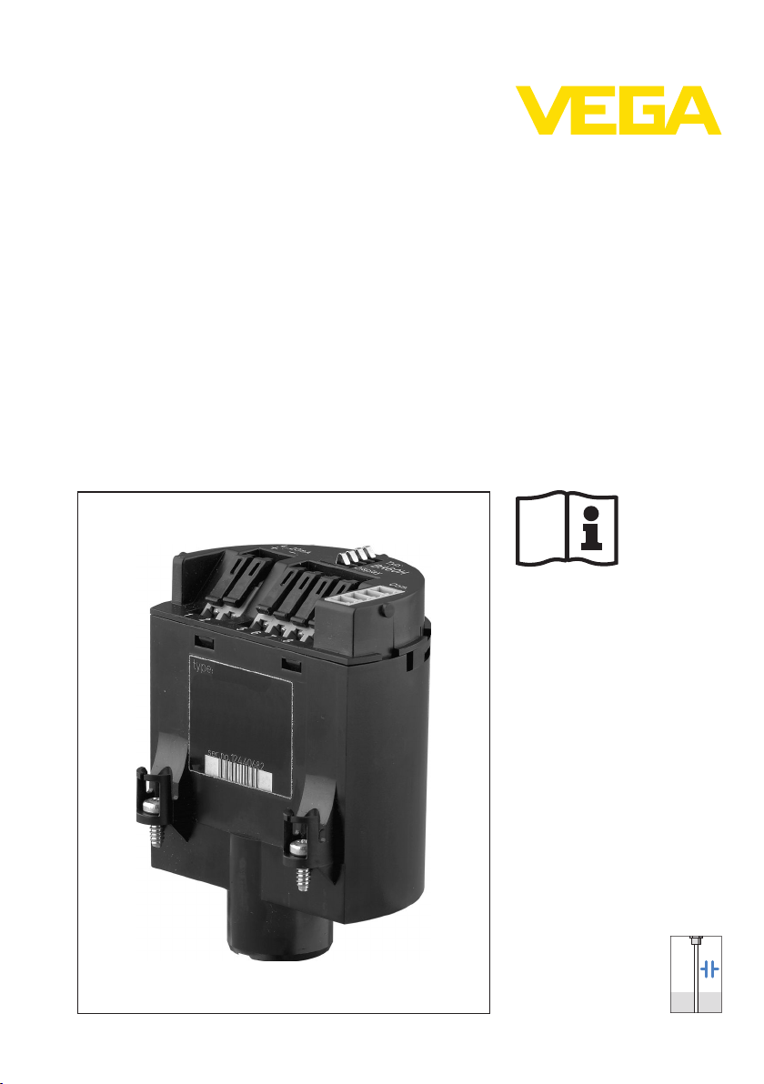
Electronics module
VEGACAL seri
es 60
Document ID:
30531
Capacitive
Page 2

Contents
Conten
1 About this document
2 For your safety
3 Product description
4 Mounting
5 Setup
6 Maintenance
ts
1.1 Function. . . . . . . . . . . . . . . . . . . . . . . . . . . . . . . . . .
1.2 Target group . . . . . . . . . . . . . . . . . . . . . . . . . . . . . .
1.3 Symbolism used . . . . . . . . . . . . . . . . . . . . . . . . . . . .
2.1 Authorised personnel . . . . . . . . . . . . . . . . . . . . . . . .
2.2 Appropriate use . . . . . . . . . . . . . . . . . . . . . . . . . . . .
2.3 Safety instructions for Ex areas . . . . . . . . . . . . . . . . .
2.4 Environmental instructions. . . . . . . . . . . . . . . . . . . . .
3.1 Structure . . . . . . . . . . . . . . . . . . . . . . . . . . . . . . . . .
3.2 Principle of operation . . . . . . . . . . . . . . . . . . . . . . . .
3.3 Packaging, transport and storage . . . . . . . . . . . . . . .
4.1 General instructions . . . . . . . . . . . . . . . . . . . . . . . . .
4.2 Mounting preparations VEGACAL . . . . . . . . . . . . . . .
4.3 Mounting steps. . . . . . . . . . . . . . . . . . . . . . . . . . . . .
5.1 Setup - Electronics 4 … 20 mA, Profibus PA,
Foundation Fieldbus . . . . . . . . . . . . . . . . . . . . . . . . .
5.2 Setup - electronics with signal conditioning instrument.
6.1 Instrument repair . . . . . . . . . . . . . . . . . . . . . . . . . . .
3
3
3
4
4
4
4
5
5
5
6
6
7
9
9
10
7 Dismounting
7.1 Dismounting steps . . . . . . . . . . . . . . . . . . . . . . . . . .
7.2 Disposal . . . . . . . . . . . . . . . . . . . . . . . . . . . . . . . . .
8 Supplement
8.1 Technical data . . . . . . . . . . . . . . . . . . . . . . . . . . . . .
2 Ele
11
11
12
30531-EN-110411
ctronics module • VEGACAL series 60
Page 3
out this document
1 Ab
1 Abou
t this document
1.1 Function
This operating instructions manual has all the information you need for
quick mounting and setup of a replacement module. Please read this
manual before you start setup.
1.2 Target group
This operating instructions manual is directed to trained qualified
personnel. The contents of this manual should be made available to
these personnel and put into practice by them.
1.3 Symbolism used
Inform
ation, tip, note
This symbol indicates helpful additional information.
Cauti
on: If this warning is ignored, faults or malfunctions can
result.
Warning: If this warning is ignored, injury to persons and/or serious
damage to the instrument can result.
Danger: If this warning is ignored, serious injury to persons and/or
destruction of the instrument can result.
applications
Ex
This symbol indicates special instructions for Ex applications.
l List
The dot set in front indicates a list with no implied sequence.
à Action
Th
is arrow indicates a single action.
1 Sequence
Numbers set in front indicate successive steps in a procedure.
30531-EN-110411
Ele
ctronics module • VEGACAL series 60 3
Page 4

2 For
your safety
or your safety
2 F
2.1 Authorised personnel
All operations described in this operating instructions manual must be
carried out only by trained specialist personnel authorised by the plant
operator.
During work on and with the device the required personal protective
equipment must always be worn.
2.2 Appropriate use
Oscillator, emitting electronics, housing or process components are
replacement components for existing sensors.
2.3 Safety instructions for Ex areas
Please note the Ex-specific safety information for installation and
operation in Ex areas. These safety instructions are part of the
operating instructions manual and come with the Ex-approved
instruments.
2.4 Environmental instructions
Protection of the environment is one of our most important duties. That
is why we have introduced an environment management system with
the goal of continuously improving company environmental protection.
The environment management system is certified according to DIN
EN ISO 14001.
Please help us fulfil this obligation by observing the environmental
instructions in this manual:
l Chapter "Packaging, transport and storage"
l Chapter "Disposal"
4 Ele
30531-EN-110411
ctronics module • VEGACAL series 60
Page 5

3 Produc
t description
Sco
pe of delivery
Application area
Packaging
Transport
3 Produc
t description
3.1 Structure
The scope of delivery encompasses:
l Electronics module VEGACAL series 60
l Documentation
- this operating instructions manual
3.2 Principle of operation
The electronics module CL 60 is suitable for exchange with capacitive
sensors VEGACAL series 60.
3.3 Packaging, transport and storage
Your instrument was protected by packaging during transport. Its
capacity to handle normal loads during transport is assured by a test
according to DIN EN 24180.
The packaging of standard instruments consists of environmentfriendly, recyclable cardboard. For special versions, PE foam or PE foil
is also used. Dispose of the packaging material via specialised
recycling companies.
Transport must be carried out under consideration of the notes on the
transport packaging. Nonobservance of these instructions can cause
damage to the device.
Transport inspection
Storage
Storage and transport
temp
erature
30531-EN-110411
Ele
ctronics module • VEGACAL series 60 5
The delivery must be checked for completeness and possible transit
damage immediately at receipt. Ascertained transit damage or
concealed defects must be appropriately dealt with.
Up to the time of installation, the packages must be left closed and
stored according to the orientation and storage markings on the
outside.
Unless otherwise indicated, the packages must be stored only under
the following conditions:
l Not in the open
l Dry and dust free
l Not exposed to corrosive media
l Protected against solar radiation
l Avoiding mechanical shock and vibration
l Storage and transport temperature see chapter "Supplement -
Technical data - Ambient conditions"
l Relative humidity 20 … 85 %
Page 6

4 M
ounting
sor serial number
Sen
4 Moun
ting
4.1 General instructions
If the electronics module is defective, it can be replaced by the user.
In Ex
applications only one instrument and one electronics module with
respective Ex approval may be used.
If there is no electronics module available on site, one can be ordered
from the VEGA agency serving you.
The new electronics module must be loaded with the order and factory
data of the sensor. These are the options:
l At the factory by VEGA
l Or on site by the user
Informa
tion:
When loading on site, first of all the order data must be downloaded
from the Internet (see "Setup").
In both cases, the sensor serial number is necessary. The serial
numbers are stated on the type label of the instrument, inside the
housing or on the delivery note.
Caution:
Th
e order data and company data contain important presettings for the
sensor. A reliable operation and a correction of the measurement is
not possible without these data.
Assignment
Electronics modules are adapted to the respective sensor. They differ,
e.g. in the signal output, the power supply or approval.
First of all check by means of the overview in section Mounting
preparations, if you are using the suitable electronics module.
Compare the new electronics module with the existing one. The
specifications on the type label must correspond. This applies mainly
to instruments with approvals.
ning:
War
Switch off voltage supply before starting the mounting procedure. The
replacement electronics must only be mounted in idle condition. Nonobservance will damage the electronics!
4.2 Mounting preparations VEGACAL
Electronics versions
6 Ele
Electronics module CL-E.60H. is suitable for VEGACAL - 4 … 20mA/
HART.
Electronics module CL-E.60P. is suitable for VEGACAL - Profibus PA.
30531-EN-110411
ctronics module • VEGACAL series 60
Page 7

1
1
ounting
4 M
ctronics module CL-E.60F. is suitable for VEGACAL - Foundation
Ele
Fieldbus FF.
Electronics module CL-E.60X. suitable for VEGACAL - with signal
conditioning instrument.
Caution:
In Ex applications only one instrument and one electronics module with
respective Ex approval may be used. Check the specifications on the
type label.
4.3 Mounting steps
Mountin
g steps
The electronics module is located in the electronics compartment. The
below illustrations show the respective position of the electronics
compartment in a single or double chamber housing.
Fig. 1: Single
1 Position of the electronics module
Fig. 2: Double
1 Position of the electronics module
chamber housing
chamber housing
Proceed as follows:
1 Switch off power supply
2 Unscrew housing cover of the electronics compartment
3 Disconnect the connection cables according to the operating
instructions manual of the respective sensor
30531-EN-110411
Ele
ctronics module • VEGACAL series 60 7
Page 8

2
1
4 M
ounting
4 Loos
en the two holding screws with a screwdriver (Torx size T 10
or Phillips size 4)
Fig. 3: Loosening
1 Electronics module
2 Screws (2 pcs.)
the holding screws
5 Pull the previous electronics out by holding the opening levers.
6 Insert the new electronics module carefully.
7 Insert the two hold screws and tighten them
8 Connect the connection cables according to the operating
instructions manual of the respective sensor
9 Screw the housing cover on
The electronics exchange is now finished.
a rule, an exchange of electronics must be documented internally
As
when Ex applications are involved.
8 Ele
30531-EN-110411
ctronics module • VEGACAL series 60
Page 9

5 Setup
5 Setup
sensor serial num-
With
ber
Without sensor serial
numbe
r
Load sensor data
Adjustment
5.1 Setup - Ele
ctronics 4 … 20 mA, Profibus PA,
Foundation Fieldbus
If you have ordered the electronics module by stating the sensor
serial number, it is ready for operation after installation and
connection to power supply.
If you have ordered the electronics module without stating the
sensor serial number or you are using a suitable electronics module
from stock, you first have to load the sensor data after installation.
In general, the sensor with the new electronics module is ready for
operation. However, the sensor name is "VEGACAL 62 " (presetting)
and the serial number is not entered correctly.
If these specifications should be correct, you have to enter the serial
number.
Move via
entering the serial number, the order data of the sensor are displayed.
The serial number is also available directly from VEGA.
Below the order data you will find "Sensor data for Service-DTM" as
XML file. Load this file with "Save as" on your PC and transfer it then
via PACTware and the Service DTM to the sensor.
As a rule, settings already carried out on site with the previous
electronics module such as min./max. adjustment etc., however must
be repe ated.
www.vega.com
to the item "serial number search". After
p:
Ti
Simply use the copy function of the adjustment module PLICSCOM or
the adjustment software PACTware.
5.2 Setup - electronics with signal conditioning
instrument
Adjustment
30531-EN-110411
Ele
ctronics module • VEGACAL series 60 9
Set all adjustment elements on the new electronics module to the
settings of the old module.
Since the electronics modules are slightly different (approx. 5 %), it
can be necessary to carry out an adjustment on the signal conditioning
instrument after having exchanged the electronics.
Page 10

6 M
aintenance
6 Maint
enance
6.1 Instrument repair
If a repair is necessary, please proceed as follows:
You can download a return form (23 KB) from our Internet homepage
www.vega.com
form".
By doing this you help us carry out the repair quickly and without
having to call back for needed information.
l Print and fill out one form per instrument
l Clean the instrument and pack it damage-proof
l Attach the completed form and, if need be, also a safety data
sheet outside on the packaging
l Please ask the agency serving you for the address of your return
shipment. You can find the respective agency on our website
www.vega.com
under: "Downloads - Forms and certificates - Repair
under: "Company - VEGA worldwide"
10 Ele
30531-EN-110411
ctronics module • VEGACAL series 60
Page 11

7 Dismoun
ting
7 Dismou
nting
7.1 Dismounting steps
Take note of chapters "Mounting" and "Connecting to power supply"
and carry out the listed steps in reverse order.
7.2 Disposal
The replacement module consists of materials which can be recycled
by specialised recycling companies. We have purposely designed the
electronic modules to be easily separable.
WEEE directive 2002/96/EG
This instrument is not subject to the WEEE directive 2002/96/EG and
the respective national laws (in Germany e.g. ElektroG). Pass the
instrument directly on to a specialised recycling company and do not
use the municipal collecting points. These may be used only for
privately used products according to the WEEE directive.
Correct disposal avoids negative effects to persons and environment
and ensures recycling of useful raw materials.
Materials: see chapter "Technical data"
If you have no way to dispose of the replacement module properly,
please contact us concerning return and disposal.
30531-EN-110411
Ele
ctronics module • VEGACAL series 60 11
Page 12

8 Suppl
ement
8 Supp
lement
8.1 Technical data
Technical data
are stated in the operating instructions manual of the respective sensor.
12 Ele
30531-EN-110411
ctronics module • VEGACAL series 60
Page 13

8 Sup
plement
30531-EN-110411
Ele
ctronics module • VEGACAL series 60 13
Page 14

8 Suppl
ement
14 Ele
30531-EN-110411
ctronics module • VEGACAL series 60
Page 15

8 Sup
plement
30531-EN-110411
Ele
ctronics module • VEGACAL series 60 15
Page 16

VEGA Grieshaber KG
ISO 9001
Am Hohenstein 113
77761 Schiltach
Germany
Phone +49 7836 50-0
Fax +49 7836 50-201
E-mail: info@de.vega.com
www.vega.com
Printing date:
statements concerning scope of delivery, application,
All
practical use and operating conditions of the sensors and
processing systems correspond to the information avail-
able at the time of printing.
© VEGA Grieshaber KG, Schiltach/Germany 2011
Subject to change without prior notice 30531-EN-110411
 Loading...