

Page 1
Model C-2000
Radio Control Console
C-2000HS C-2000
Technical Manual
March 26, 2003 P.N. 0980380
Revision B
Page 2

Page 3

Remote Control Console i
Table of Contents
1 INTRODUCTION...................................................................................................................................................................1
2 HARDWARE OVERVIEW ...................................................................................................................................................1
2.1 C-2000 CONSOLE..............................................................................................................................................................1
2.1.1 Main PCB...............................................................................................................................................................1
2.1.2 Keypad PCB...........................................................................................................................................................1
2.1.3 Line Interface.........................................................................................................................................................1
3 CONTROLS AND INDICATORS.......................................................................................................................................2
3.1 FRONT PANEL ..................................................................................................................................................................2
3.1.1 Common Controls and Indicators.....................................................................................................................2
3.2 REAR PANEL CONNECTIONS .........................................................................................................................................3
3.2.1 Rear Panel Ports...................................................................................................................................................3
4 LINE SETUP AND DESCRIPTION.....................................................................................................................................4
4.1 INTRODUCTION/DEFAULTS......................................................................................................................................4
4.2 FEATURE DESCRIPTION..............................................................................................................................................4
4.2.1 Crossmute ............................................................................................................................................................... 4
4.2.2 U2 OPTO Isolator.................................................................................................................................................4
4.2.3 J22...........................................................................................................................................................................4
4.2.4 Supervisor Function.............................................................................................................................................5
4.2.5 Relay Contact Closure For Local Control......................................................................................................5
4.2.6 Two-Wire/Four-Wire Mode.................................................................................................................................5
4.2.7 RX Side Settings....................................................................................................................................................5
4.2.8 TX Side Settings....................................................................................................................................................6
4.2.9 Transmit Monitor..................................................................................................................................................6
4.3 LEVEL ADJUSTMENTS....................................................................................................................................................6
4.3.1 Transmit Side Adjustments..................................................................................................................................6
4.3.2 Transmit Monitor Setup.......................................................................................................................................7
4.3.3 RX Level Adjustment.............................................................................................................................................7
5 SETUP MODE.........................................................................................................................................................................7
5.1 ENTERING SETUP MODE...............................................................................................................................................7
5.2 EXITING SETUP MODE...................................................................................................................................................8
5.3 MANEUVERING THROUGH SETUP MODE...................................................................................................................8
5.3.1 Setup Mode Control Keys...................................................................................................................................8
5.3.2 Setup Mode Philosophy.......................................................................................................................................8
5.4 SETUP STATES AND SETUP STATE OPTIONS...........................................................................................................8
5.4.1 Setup State 0 PIN Number Entry......................................................................................................................10
5.4.2 Setup State 1 PIN Number Change.................................................................................................................10
5.4.3 Setup State 2 Guard/Hold Tone Frequency...................................................................................................10
5.4.4 Setup State 3 Guard Tone Level.......................................................................................................................10
5.4.5 Setup State 4 Guard Tone Duration................................................................................................................10
5.4.6 Setup State 5 Hold Tone Level.........................................................................................................................11
5.4.7 Setup State 6 Hold Tone PTT Hang Time.......................................................................................................11
5.4.8 Setup State 7 Function Tone Level..................................................................................................................11
5.4.9 Setup State 8 Function Tone Duration...........................................................................................................11
5.4.10 Setup State 9 Single/Dual Function Tone Mode..........................................................................................11
5.4.11 Setup State 10 Function Tone Frequency......................................................................................................11
5.4.12 Setup State 11 Monitor Frequency Select.....................................................................................................13
5.4.13 Setup State 12 DTMF Keypad Enable/Disable/Enable(without PTT).....................................................13
5.4.14 Setup State 13 DTMF Tone Level....................................................................................................................13
5.4.15 Setup State 14 DTMF Hang Time ....................................................................................................................13
5.4.16 Setup State 15 MIC AGC Enable/Disable......................................................................................................13
5.4.17 Setup State 16 RX AGC Enable/Disable........................................................................................................13
5.4.18 Setup State 17 Main Speaker with Handset Enable/Disable.....................................................................13
5.4.19 Setup State 18 SF Mode Enable/Disable ***...............................................................................................13
5.4.20 Setup State 19 Aux Speaker Enable/Disable................................................................................................14
Page 4

ii Vega’s C-2000
5.4.21 Setup State 20 Function Tone Enable/Disable.............................................................................................14
5.4.22 Setup State 21 Crossmute Output Enable/Disable.......................................................................................14
5.4.23 Setup State 22 Min Speaker Level Enable/Disable.....................................................................................14
5.4.24 Setup State 23 Handset Mic Level...................................................................................................................14
5.4.25 Setup State 24 Deskmic Level...........................................................................................................................14
5.4.26 Setup State 25 Aux Input Port Level...............................................................................................................14
5.4.27 Setup State 26 Panel microphone Input Level..............................................................................................14
5.4.28 Setup State 27 RX Line Jack Level..................................................................................................................15
5.4.29 Setup State 28 TX Line Jack Level..................................................................................................................15
5.4.30 Setup State 29 Clone Mode..............................................................................................................................15
5.4.31 Setup State 30 Full Duplex Mode Enable/Disable......................................................................................16
5.4.32 Setup State 31 Handset Enable/Disable........................................................................................................16
5.4.33 Setup State 32 Auto-Monitor Enable/Disable..............................................................................................16
5.4.34 Setup State 33 Tone/Local Mode.....................................................................................................................16
5.4.35 Setup State 34 Squelch Level...........................................................................................................................16
5.4.36 Setup State 35 Squelch Enable/Disable.........................................................................................................16
5.4.37 Setup State 36 Squelch Hang Time .................................................................................................................16
5.4.38 Setup State 37 TX Monitor Enable/Disable..................................................................................................16
5.4.39 Setup State 38 Tone Detector Threshold........................................................................................................17
5.4.40 Setup State 39 Headset Enable/Disable.........................................................................................................17
5.4.41 Setup State 40 TX Delay Period.......................................................................................................................17
5.4.42 Setup State 41 Desk Microphone Enable/Disable.......................................................................................17
5.4.43 Setup State 42 Ring Type Select ***..............................................................................................................17
5.4.44 Setup State 43 EMSTEL Enable/Disable ***...............................................................................................18
5.4.45 Setup State 44 DTMF Sequence Entry............................................................................................................18
5.4.46 Setup State 45 Ring Duration ***..................................................................................................................18
5.4.47 Setup State 46 DTMF Sequence Enable/Disable.........................................................................................18
5.4.48 Setup State 47 Function Tone Launch Delay................................................................................................18
5.4.49 Setup State 48 Parallel Update Enable/Disable..........................................................................................19
5.4.50 Setup State 49 Alert Tone Enable/Disable....................................................................................................19
5.4.51 Setup State 50 Alignment Tone ON/OFF.......................................................................................................19
6 THEORY OF OPERATION................................................................................................................................................20
6.1 AUDIO INPUT PATHS....................................................................................................................................................20
6.2 AUDIO OUTPUT PATHS ...............................................................................................................................................20
6.3 LINE RECEIVE PATH .....................................................................................................................................................20
6.4 SYSTEM CLOCK G ENERATION....................................................................................................................................21
6.5 NON-V OLATILE MEMORY (EEPROM).......................................................................................................................21
6.6 USER I/O..........................................................................................................................................................................21
6.7 CLONE MODE SERIAL PORT .......................................................................................................................................21
6.8 POWER REGULATION AND RESET CONTROL...........................................................................................................21
7 WARRANTY, SERVICE, REPAIR, AND COMMENTS................................................................................................22
8 SPECIFICATIONS...............................................................................................................................................................23
9 TECHNICAL DOCUMENTATION....................................................................................................................................24
9.1 PCB ASSEMBLY, C-2000 MAIN BOARD P.N. 879399.................................................................................................24
9.1.1 PCB # 750539 Rev. A.........................................................................................................................................24
9.1.2 PCB # 750539 Rev. B.........................................................................................................................................24
9.2 SCHEMATIC, C-2000 MAIN BOARD, P.N. 770651......................................................................................................24
9.2.1 SCH # 770651 Rev A..........................................................................................................................................24
9.2.2 SCH # 770651 Rev B..........................................................................................................................................24
9.3 PCB ASSEMBLY, C-2000 KEYPAD BOARD, P.N. 879400...........................................................................................24
9.4 SCHEMATIC, C-2000 KEYPAD BOARD, P.N. 770652.................................................................................................24
9.5 C-2000 TOP ASSEMBLY, P.N. 0110188........................................................................................................................24
Page 5

Remote Control Console iii
Table of Tables
Table 1 Setup States. ........................................................................................................................................................9
Table 2 Guard/Hold Tone..............................................................................................................................................10
Table 3 Guard Tone Level.............................................................................................................................................10
Table 4 Guard Tone Dur................................................................................................................................................10
Table 5 Hold Tone Level................................................................................................................................................11
Table 6 PTT Hang Time ................................................................................................................................................11
Table 7 Function Tone Level.........................................................................................................................................11
Table 8 Function Tone Dur...........................................................................................................................................11
Table 9 S/D Function Mode...........................................................................................................................................11
Table 10 Available Function and Monitor frequencies............................................................................................12
Table 11 DTMF Tone Level...........................................................................................................................................13
Table 12 Function Tone Dur.........................................................................................................................................13
Table 13 Handset MIC Level.........................................................................................................................................14
Table 14 Deskmic Level................................................................................................................................................14
Table 15 Aux Input Level...............................................................................................................................................14
Table 16 Panel MIC Level.............................................................................................................................................14
Table 17 RX Line Level.................................................................................................................................................15
Table 18 TX Line Level.................................................................................................................................................15
Table 19 Squelch Level..................................................................................................................................................16
Table 20 Tone Detector .................................................................................................................................................17
Table 21 TX Delay Period.............................................................................................................................................17
Table 22 Ring Tones......................................................................................................................................................17
Table 23 DTMF Sequence.............................................................................................................................................18
Table 24 F -tone Launch.................................................................................................................................................18
Table 25 Table of Notes for C-2000 personality.......................................................................................................19
Table 26 Table of Notes for C-2000 Function Tone Frequencies..........................................................................19
Table of Figures
Figure 1 Front Panel Diagram.......................................................................................................................................2
Figure 2 Rear Panel Diagram........................................................................................................................................3
Figure 3 Rear Panel Pinout............................................................................................................................................3
Figure 4 Line Connector Pin Out.................................................................................................................................4
Figure 5 Crossmute Function example........................................................................................................................4
Figure 6 Supervisor Function Example........................................................................................................................5
Figure 7 Master/Slave Console Configuration...........................................................................................................6
Figure 8 Serial Cable Diagram. ..................................................................................................................................15
Page 6

iv Vega’s C-2000
C-2000 DEFAULT SHIPPING CONFIGURATION:
The C-2000HS is shipped from the factory in the following state:
1) 4 Wire Mode
2) Full Duplex
3) TX Monitor Enabled
4) F3 – F16 Disabled
5) 600 Ohm TX output impedance
6) 600 Ohm RX input impedance
The C-2000 is shipped from the factory in the following state:
1) 4 Wire Mode
2) Full Duplex
3) TX Monitor Enabled
4) F3 – F16 Disabled
5) 600 Ohm TX output impedance
6) 600 Ohm RX input impedance
7) Handset Disabled
8) Desk Microphone Enabled.
DISPLAY CHARACTER DESCRIPTION
CC Clone Complete: Cloning has successfully completed.
CL Clone Mode: Clone Mode has been entered.
C? CrossMute: Another parallel console is active and pull Crossmute low.
CP Correct PIN: The PIN number was correctly entered.
EE Error: An Error has occurred, seen in Clone Mode if cloning fails.
EP Enter Pin: A PIN number needs to be entered to access Setup Mode.
Fd Function Duration: Function Duration programming Mode has been entered.
FF Function Frequency: Function Frequency programming Mode has been entered.
IP Incorrect PIN: An incorrect PIN number was entered.
OC Option Changed: The option selected and been changed.
PC PIN Changed: The PIN was successfully changed.
SS Settings Saved: The current settings have been permanently saved.
SU Supervisor: The supervisor pin has been activated by a parallel console.
Page 7

Remote Control Console 1
1 Introduction
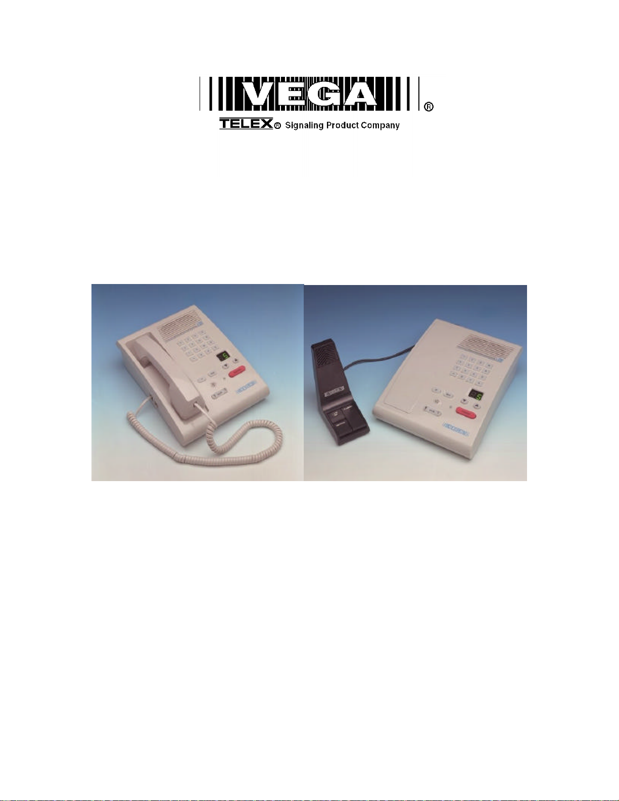
The model C-2000 is a full featured single -channel, multi-format, and self-contained desktop radio control console.
Its sleek and modern look will compliment any surroundings.
The C-2000 is a Digital Signal Processor (DSP) based design, allowing easy field programmability using the DTMF
keypad on the front of the console. Unlike other manufacturers’ equipment, no additional software is required to
program the C-2000 console. Modifications and enhancements can generally be made via a software change only. If
the user determi nes they require a special feature enhancement, please contact the Vega Sales Department for cost
and feasibility.
Initial Line level adjustments are made via potentiometers allowing for ease of installation. Should additional
adjustments be required, they can be made in the programming mode. AGC on the receive and microphone audio
paths help stabilize line level adjustments.
The C-2000’s modular design offers control of one base station, along with selection of 99 frequencies. The line
interface offers crossmute capability and squelch control feature eliminating the unwanted noise that is generally
associated when monitoring a line.
The C-2000 will accommodate a desk microphone along with a handset (or headset) as indicated on the side of the C2000 console. In addition to the external microphone options, a built in panel microphone is available by pressing the
PTT on the front of the panel. When a PTT occurs from any of the three microphones, the others will mute so as not
to pick-up unnecessary ambient noise during transmission. When the handset is enabled and taken off hook the
receive audio is transferred to the earpiece.
The console is normally used in conjunction with a matching Vega 223 Series (or equivalent) tone-remote panel
located at the base station. The console is compatible with Motorola, MA/ComNet Ericsson/GE, and other toneremote control systems employing the industry-standard sequential tone-control format.
The console is connected to the mating panels by means of shielded voice-grade or better leased or private lines
(including microwave circuits). Metallic or DC continuity is not required.
2 Hardware Overview
The C-2000 is a single -line, multi-mode console designed specifically for small to medium level system requirements.
All functions are housed in a single small modern looking console.
2.1 C-2000 Console
The C-2000 consists of the following two sub-assemblies enclosed in the single case: Main Processing Board and
Keypad/Display Board.
2.1.1 Main PCB
The Main PCB is mounted to the bottom of the enclosure using 4 #6 screws. It contains the DSP that handles all
audio processing and user interface features. One stereo Digital to Analog Converter (DAC) is utilized to generate
audio for transmission, handset sidetone, and receive audio. One stereo Analog to Digital Converter (ADC) on the
main board digitizes audio from the line, microphone and the auxiliary interface. All audio detection, generation, and
filtering are performed within the DSP. Five potentiometers are available for I/O signal level adjustment, in addition to
the software level control.
2.1.2 Keypad PCB
The Keypad board is interfaced to the main board via a 34-pin ribbon cable. The Keypad board contains the LED’s,
the entire key map matrix, the dual seven-segment display and the panel mi crophone. The driver circuitry for each
component is located on the Main PCB.
2.1.3 Line Interface
The Line Interface is an 8 pin RJ-45 connector, using either the standard tone control format compatible with
Motorola and M/A ComNet Ericsson/GE or Local Control relay closure. The line interface may be hardware
Page 8
2 Vega’s C-2000
IC
4 5 6 B 7 8 9 C
*
configured for either two-wire or four-wire operation and may be factory modified to accommodate non-industry
standard tone control formats if desired. This is usually a software only change.
3 Controls and Indicators
1 2 3 A
#
VOLUME
0
MON
D
TRANSMIT
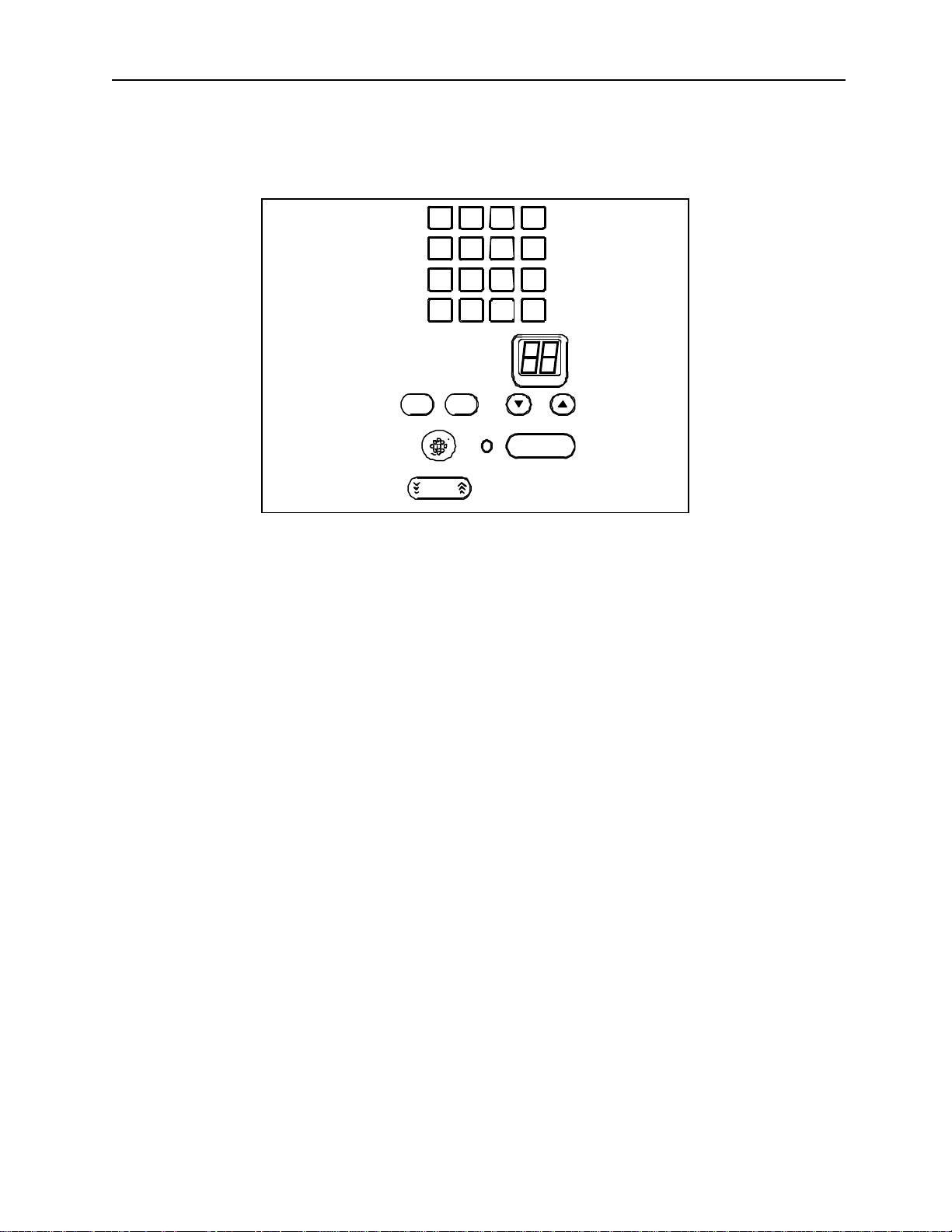
Figure 1 Front Panel Diagram
3.1 Front Panel
Figure 1 shows a view of the Front panel. The Front panel contains the user I/O. It features volume and Function
Tone selection, intercom and monitor functions, DTMF keypad, panel PTT and microphone, as well as the dual
seven-segment display.
3.1.1 Common Controls and Indicators
Volume Control: Adjusts the receive audio speaker and handset level of the audio present on the receive inputs of
the line interface. A minimum volume level can be set in the setup mode so that the console operator can not turn the
volume to zero. When adjusting the level up or down, the display shows the selected level on a relative scale with 0
being off and 25 being full volume.
Panel PTT Pushbutton: When pressed, audio from the panel microphone, or desk microphone if enabled, will be sent
on the TX line interface.
DTMF Keypad: The DTMF keypad is used for transmitting DTMF. The DTMF keypad is also used in the setup
mode. It can also be disabled in user mode.
Dual Seven-Segment Display: Displays selected frequency and will update with parallel frequency selection if active.
Function Buttons Up-Down: The Up and Down arrows, just below the display, are used to select the desired function
tone. Pressing the arrows changes the value in the desired direction. Once the desire function tone is selected, the
unit will pause, blink and then send the function tone shown on the display. The pause and blink rate are
programmable in setup mode. Only enabled function tones are displayed and transmitted. No hold tone is associated
with the changing of the function tone. A function tone shall remain selected until the operator changes the setting.
Transmit LED: This LED lights when any PTT source is depressed keying up the console. It will also blink if a Hold
tone is detected on the TX audio line. This would indicate to the operator that another console is currently
transmitting on the channel.
Monitor: When the Monitor button is pressed a Monitor tone burst is sent out. The Monitor tone burst consists of
a guard tone and function tone of 2050Hz(default value). The MON LED lights for the duration of the tone burst.
Page 9
Remote Control Console 3
1 2 3 4 5 6 7 8
1 2 3 4 5 6
1 2 3
Intercom (IC): When the Intercom button is pressed and held down the C-2000 shall transmit audio without
activating the tone generator or local relay. Intercom is considered a PTT operation with the tone generator and local
control relay disabled. The selected microphone is based on setup and/or hook switch status.
3.2 Rear Panel Connections
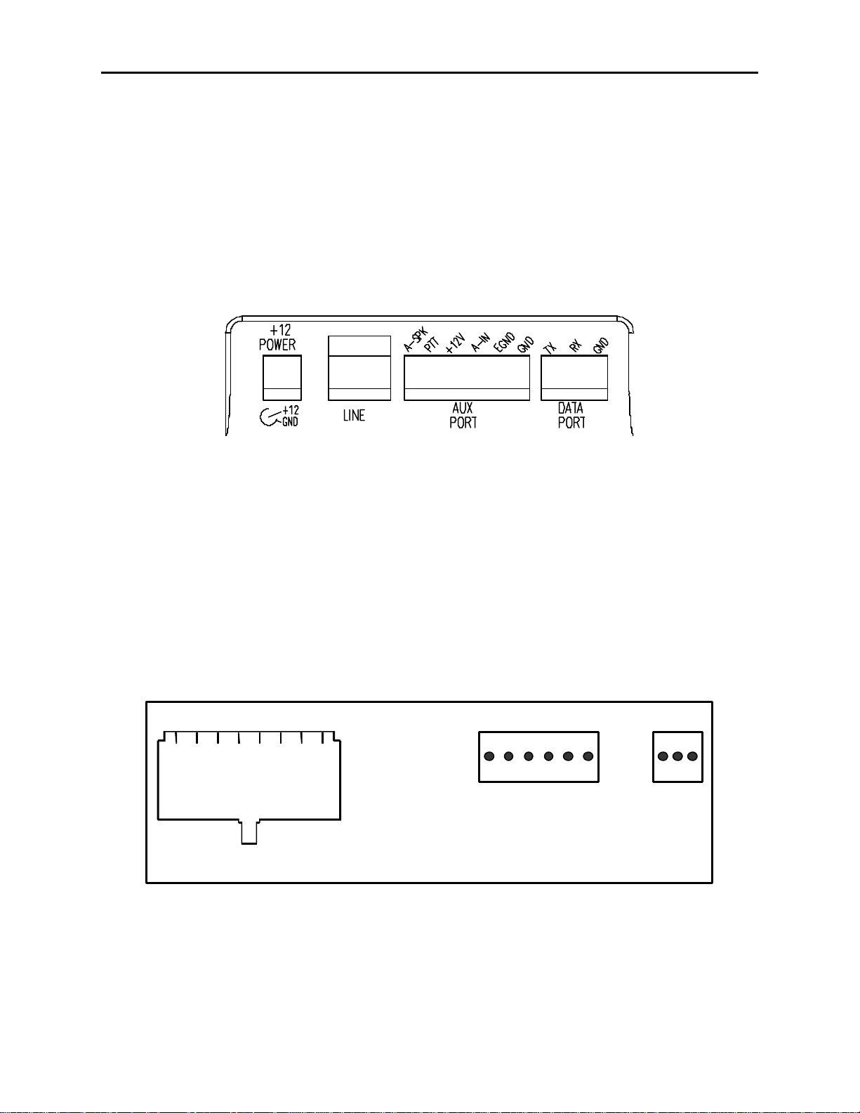
Figure 2 shows drawing of the rear panel of the C-2000. Each of the ports shown is discussed in detail in the
following section.
3.2.1 Rear Panel Ports
Power Jack: The left most jack on the C-2000 is the Power Jack. The power supply that is included with the unit
plugs in to this location. It is a standard 2.5mm center positive plug and requires at least 12V to operate correctly.
Figure 2 Rear Panel Diagram
Line Port: The C-2000 is equipped with a single line jack. It is the second connector from the left. The connector is a
standard eight pin RJ -45. The pinout of the connector appears in Figure 3. The numbering of the pins are shown in
Figure 3 for reference. In addition to the standard RX and TX pin pairs, the unit also can be supervised and supports
cross mute functions. Pins 7 and 8 of the Line connector can be used as a form C closure relay for local control. Pins
7 and 8 form the closure during any PTT operation. An internal resistor makes an external connection to ground unnecessary, and can be removed to remove ground from the closure path.
Auxiliary Audio Input: The external 6 pin terminal block provides an Audio Input (1), PTT (2), and GND (6) line.
Pulling PTT to ground activates the Audio Input line for transmitting audio from an external source. This input is a
high impedance capacitance coupled input.
Auxiliary Speaker: Pin 1 of the AUX Port is a capacitance coupled low impedance output that can be used to drive
an external speaker amplifier. Output level is controlled by the front panel volume control.
1) Cross Mute I/O
2) Supervisor I/O
3) RX +
4) TX +/(RX+2W)
5) TX -/(RX - 2W)
6) RX -
7) Local
8) GND/Local
Rear Panel Connector Pinouts
1) RX Audio 2) PTT
3) +12V 4) Aux Audio In
5) Earth GND 6) Sig GND
1) TXD
2) RXD
3) GND
Figure 3 Rear Panel Pinout
Battery backup: The +12V power input on the AUX Port is used for battery backup and is a diode-protected input.
Earth Ground: The Earth ground connection on the AUX Port MUST be connected for proper operation. It provides
a path for any external noise to be shunted to.
Data port: This port is a 0 to 10V asynchronous port used for cloning one C-2000 to another. The cable is not
supplied but the connector is. To connect two units, RX on one console should be connected to TX of the other
console. Ground is connected straight through. This is a non-standard serial port used only for the C-2000 cloning
function. Refer to 5.4.30 for details.
Page 10
4 Vega’s C-2000
1 2 3 4 5 6 7 8
Line +
4 Line Setup and Description
4.1 INTRODUCTION/DEFAULTS
1) Cross Mute I/O
2) Supervisor I/O
3) RX +
4) TX +/ (RX + 2W)
5) TX -/ (RX - 2W)
6) RX -
7) Local
8) GND/Local
Connector View
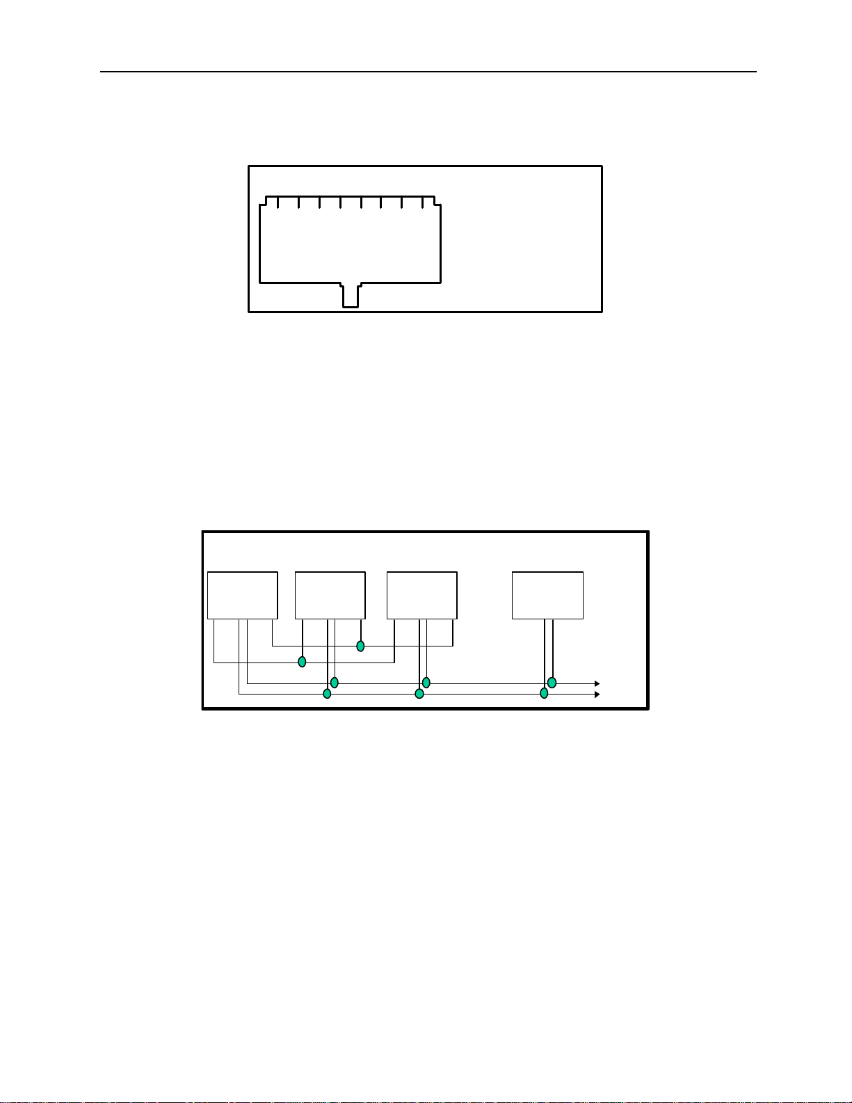
Figure 4 Line Connector Pin Out
The Line interface for the C-2000 console provides communication with any standard tone remote system. Figure 4
shows the pin out of the line interface connector, which is on the rear panel (See Figure 2 and Figure 3).
4.2 FEATURE DESCRIPTION
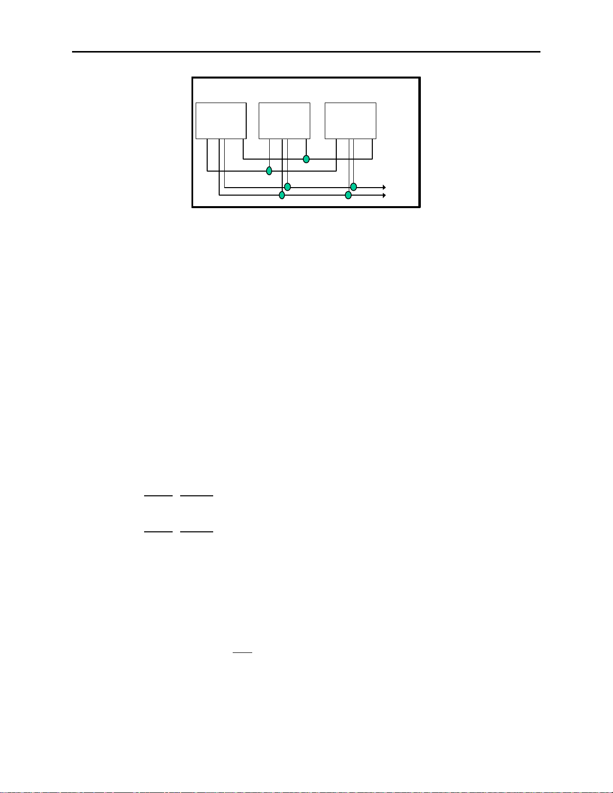
4.2.1 Crossmute
When a parallel console operator keys a microphone in the same room, the crossmute function mutes the receive
audio path of the other parallel consoles. This prevents any unwanted audio loops that could occur, causing a loud
squeal on the paralleled speakers.
Console 1: Console 2: Console 3:
Offsite
Console 4:
Line 1
1 2 3 4 5 6 7 8 1 2 3 4 5 6 7 8 1 2 3 4 5 6 7 8 1 2 3 4 5 6 7 8
Line 1Line 1Line 1
Line -
Figure 5 Crossmute Function example.
Feedback may be avoided by muting the receive audio of the other consoles which are in parallel with a transmitting
console. This may be accomplished by connecting pins 1 and 8 of each of the consoles to be crossmuted as shown
in Figure 5. Pin 8 must be connected to provide a common ground. Figure 5 illustrates the connections between
consoles 1 through 3 that are in the same room and when one transmits, the receive audio on the other consoles will
be muted. Console 4 is off-site with no possibility of feedback, therefore, it is not connected and will not be muted.
Note: The intercom function will not work between crossmuted consoles.
4.2.2 U2 OPTO Isolator
U2, J18, J19 and J21 have been added to Main PBC rev B and tied in parallel to the X-Mute and Supervisory logic.
Currently there is no programmed functionally within the unit and J18 and J21 should remain to the “B” position.
4.2.3 J22
J22 is a factory test jumper and not used in the field.
Page 11
Remote Control Console 5
4.2.4 Supervisor Function
Console 1: Console 2: Console 3:
Line 1
1 2 3 4 5 6 7 8 1 2 3 4 5 6 7 8 1 2 3 4 5 6 7 8
Figure 6 Supervisor Function Example.
The Supervisor Function enables a console, such as the C-1610, which has the capability to drive this line, to disable
all units on a particular line. This includes both PTT and RX audio. Its connection is similar to that of the crossmute
function. By wiring alone, it is possible to setup only specific consoles with this feature. Figure 6 shows the
connection scheme required to utilize this function. Pin 2 of all consoles are connected together. In addition, Pin 8 is
also connected together on all consoles, serving as a common ground for all consoles. Assuming that console 1 has
supervisory capability, when activated, Line 1 on parallel consoles 2 and 3 would then be inhibited from both
Transmit and Receive. In addition, the C-2000 will display “SU” on the seven segment display if a master console,
such as the C-1610, activates the Supervisor function.
Line 1Line 1
Line Line +
4.2.5 Relay Contact Closure For Local Control
The relay is normally open and provides a dry contact closure during PTT functions between pins 7 and 8 of the line
jack. The relay closure can carry 500mA at 12VDC or 250mA at 115VAC. When using the intercom function the relay
is not activated. If this relay closure is used for local control (or any other case where tone bursts are not used for
signaling) disabling the tone generation is recommended by entering the setup mode. J20 allows for a circuit ground
to be coupled to the relays common pin. “A” position = Grounded, “B” = Loop
4.2.6 Two-Wire/Fou r-Wire Mode
The C-2000 comes standard with a jumper selectable two or four -wire option. Note: The C-2000 is shipped in the fourwire mode. Two-wire mode is accomplished by the following jumper positions:
Two-Wire: Jumper Position
JP10 A
JP11 A
Four-Wire: Jumper Position
JP10 B
JP11 B
The RX pair is now on pins 3 and 6 on the connector and the TX pair is on pins 4 and 5. Once the transmit and
receive paths are separated the impedance of each side must be set.
4.2.7 RX Side Settings
In 4 Wire mode, the RX side is jumper selectable for a 600 ohm impedance or 10k ohm impedance. If only one console
is on the line (no parallel consoles) then place J8 in the A position for a 600 Ohm line impedance. If more than one
console is on one line, then place J8 on ONE console in the A position and all other consoles in the B position. Each
console added to the system will result in line loss. The following chart gives an indication as to how much loss can
be expected. The first console in the system is set for an impedance of 600 ohms out (approximately). Each console
added to the system thereafter is set for an impedance of 10k ohms. As the chart indicates on the following page, the
more consoles bridged on the line, the lower the line impedance and the greater the loss in audio level. In 2 Wire
mode, all consoles should have J8 in the “B” position.
Page 12
6 Vega’s C-2000
Console # J8 Position Impedance Impedance Loss (dB)
1 A 604 604 0.0
2 B 10k 569 -0.5
3 B 10k 539 -1.0
4 B 10k 511 -1.5
5 B 10k 486 -1.9
6 B 10k 464 -2.3
Level adjustment can be made to the receive audio by entering the setup mode or adjusting the RX level POT inside
the C-2000.
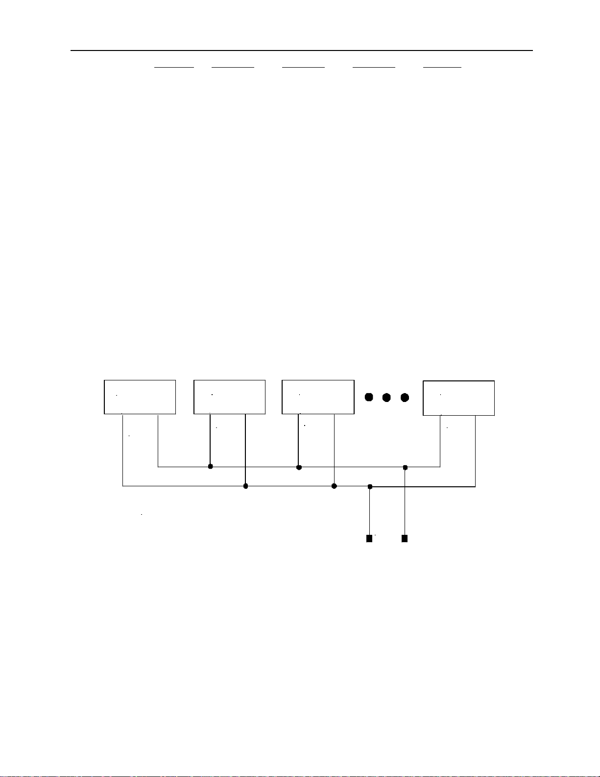
4.2.8 TX Side Settings
The C-2000 TX output circuitry has a DPDT relay that is used to connect and disconnect the TX output transformer
from the TX line based on PTT status. This allows a very large number of consoles to be attached to the line in
parallel, because only the transmitting unit will be directly connected to the line. When not transmitting, the DPDT
relay is connected to 600 ohms or open circuit depending on the number of console connected in parallel to the line.
If only one console is attached, this unit should have J12 in the “A” position. This makes it the effective master and
terminates the line with 600 ohms. If there is more than one console connected in parallel, one console should be
designated as the master by placing J12 in the “A” position. The remaining consoles should be designated as a slave
and should have J12 placed in the “B” position. In this manner, the impedance looking back into the parallel
configuration of consoles is still 600 ohms. Figure 7 shows the basic configuration. The C-1610 could also be the
master in this configuration. NOTE: If any of the consoles connected in parallel are not C-2000’s, then all the C-2000’s
should be configured as slaves. Additionally, J14 should be used as a TX line impedance correction if there are
consoles other than the C-2000 connected in parallel. J14 position “B” adds another 600ohms to the output TX line.
J14 Position “A” is straight through.
Master
J12 POS A
600
Slave
J12 POS B
open
Slave
J12 POS B
open
Slave
J12 POS B
open
ohms
C2000 Multiple Console Configuration
Leased
Line
Figure 7 Master/Slave Console Configuration.
4.2.9 Transmit Monitor
In a four-wire system with parallel consoles, the transmit line may be monitored. Refer to section 4.3.2, the monitor
level setup on adjusting the level. The transmit monitor is not needed in two -wire mode as the transmit audio is
already on the receive circuit. The transmit monitor, in 4 wire mode, is used to detect transmit activity for the TX
Detect LED.
4.3 Level Adjustments
4.3.1 Transmit Side Adjustments
The transmit audio consists of multiple audio sources – microphone audio, AUX input, function tones, and DTMF
tones. Each audio sources is summed or generated in the DSP with the analog signal being generated on a single
DAC. The following is a list of the potentiometers that affect the transmit path.
Page 13

Remote Control Console 7
Reference Description
R171 TX Output Level Adjustment
R105 Desk Microphone Adjustment
R115 Hand Set Microphone Adjustment
MIC INPUT LEVEL ADJUST:
Care should be taken to avoid overdriving the input TX circuitry, as this will distort the audio. Make sure you have
enabled the desired Microphone connection in setup mode. Saying and holding the word “Four” is a good audio
level test vocalization. Use a strong tone of voice.
When adjusting the Hand Set audio input level connect a oscilloscope to Test point TP3 and adjust R115. Speak into
the Hand Set and adjust the audio to approximately 3.5Vp -p. A portion of the handset audio will be routed to the
Hand set earpiece, this level is adjustable in setup mode.
For the Desk Microphone input, repeat the sequence only monitor Test point TP2 and adjust R105. Make sure that
the Desk Microphone is at the normal distance from the operator when setting the level.
TX OUTUT LEVEL ADJUST:
The transmit level potentiometer is used to adjust the output level of the transmit audio so that it is calibrated with
the tone levels that were set in setup mode. Calibration of the TX line will vary depending on system variables as
well as the number of consoles found in parallel on the line. A easy way to align the console for the correct level is to
press and hold the PTT key. While the console is keyed up, the unit will by default be generating a Hold tone at –
20dBm. A meter reading dBm can then be used and R171 adjusted to read the correct value. Also a alignment tone,
Section 5.4.51 Setup state 50 is provided (REV.2.3 and higher operating software).
4.3.2 Transmit Monitor Setup
The transmit monitor provides a portion of the transmit audio of a four-wire circuit to the receive path. This allows
the console operator to listen to the transmissions of parallel console operators. To set this level have a parallel
console operator press the intercom button. Adjust R104 until the level is comfortable in the handset/headset
earpiece or the speaker. Make sure this feature is enabled or no audio will be passed. See Setup Mode.
4.3.3 RX Level Adjustment
The RX level should be adjusted so that the maximum level coming into the console use the entire range of the ADC,
which is 0-4V. A test tone of +3dBm to -5dBm coming into the line interface is a good value to use. Adjust R89 so
that the signal seen on an oscilloscope at Test point TP4 is approximately 3.8Vp-p.
5 Setup Mode
5.1 Entering Setup Mode
Entry into the C-2000 Setup mode is accomplished by pressing and holding the “IC-MON” keys, then pressing the
“2” key. The IC and MON buttons will stay lit when in setup mode. If a PIN number is required, an “EP” will appear in
the display requesting that the four-digit number be entered. If the number is entered incorrectly, the C-2000 will
display “IP”, for incorrect PIN, and return to user mode. No PIN number is required if the system defaults are set.
Default values can be restored to the unit buy Pressing and holding the Function Up and Function Down keys when
power is applied to the unit . If a PIN number has been set, it will be requested before resetting to default values, if the
PIN is entered incorrectly the C-2000 will not reset its values to default and will enter the user mode. PIN numbers can
be enabled/disabled/changed in Setup Mode, see section 5.4.2. If the PIN number is lost or forgotten, a system
override is available that will set all parameters back to default. To reset the system parameters, power down the unit.
Open the case and disconnect the speaker. Next, place test jumper J17 in the “A” position and power up. This mode
resets defaults and does a system test. The C-2000 has now stored system defaults, which includes no PIN number.
Power down and place J17 in the “B” position. Connect the speaker, close the case and power up the unit.
Page 14

8 Vega’s C-2000
5.2 Exiting Setup Mode
Exiti ng Setup Mode is done the same manner as entering Setup Mode. Pressing and holding the “IC-MON” keys,
then pressing the “2” key will return the user to normal operation mode. Note, settings will be saved on exit. To save
settings before exiting setup mode, press and hold the “IC” key and then press the “D” key.
5.3 Maneuvering Through Setup Mode
5.3.1 Setup Mode Control Keys
The main control keys are:
VOLUME UP and DOWN: Selects the Setup State by scrolling up and down through the allowed states.
FUNCTION UP and DOWN: Selects the Setup Option for the current Setup State by scrolling through the
allowed options for that state.
DTMF POUND KEY (#): Used as the Enter Key. Pressing this key will enter the current option for the
current state. It also takes you into a more complicated mode if more than a
simple enable/disable is required.
DTMF STAR KEY (*): Used as the Escape Key. Pressing this key will exit without saving from certain
setup states that require it. Note: Only a few states use this key.
DTMF A and B KEYS: These keys are used to program Function Tone Frequencies main and sub-tone.
It is also used to select Clone mode Master or Slave.
IC and D KEY: Pressing and holding IC, then pressing D will save the changes made to Setup
Mode.
IC and MON KEYS: Pressing these keys together while in the PIN CHANGE state will disable the PIN.
Note: This key sequence is not used in any other state.
TRANSMIT KEY: This key is used to display the current Setup State, once the display has
changed to the setup option.
5.3.2 Setup Mode Philosophy
Once Setup Mode is entered, the operator will use the VOLUME UP and DOWN keys to select the Setup State. The
Setup State is the system function that the operator wishes to change or enable. The display will show the Setup
State number and both decimal points for 1 second and then change to the Setup State option number that is
currently programmed, with no decimal point. If you wish to review the Setup State while the setup option is being
displayed, simply press the TRANSMIT key on the front panel and the current Setup State will be displayed as long
as the key is held. Once you have scrolled to your desired Setup State and the display has changed to that states
currently programmed setup option, the operator can now use the FUNCTION UP and FUNCTION DOWN keys to
scroll to the appropriate setup option. The display will show the setup option number and NO decimal points. The
selection will only scroll to those option values that are available to that Setup State, i.e., an enable/disable Setup
State will have option 1 and 2, with 1=enable and 2=disable and no other. Now pressing the ENTER (#) key will
program the selected option for the current state. Once programming completes, the display will show “OC” for
option changed, then display the current Setup State.
Saving the changes made to a Setup State is done by pressing and holding “IC” and pressing “D”. The display will
show “SS” for saving settings, and then returns to the current Setup State. Exiting Setup Mode automatically saves
the settings. If the settings are not saved and power is lost, the changes will be discarded.
There are certain Setup States that have more complex user interface features. These will be detailed in each Setup
State section.
5.4 Setup States and Setup State Options
SETUP STATE SETUP STATE NAME AND BREIF DESCRIPTION
0 PIN Number Entry/Idle: Automatically entered when Setup Mode is accessed.
1 PIN Number Change: Used to change the Setup Mode PIN number.
2 Guard/Hold Tone Frequency: Selects between 2175Hz and 2300Hz.
3 Guard Tone Level: Sets the level of the Guard tone.
4 Guard Tone Duration: Sets the Guard tone duration
5 Hold Tone Level: Sets the Hold tone level
Page 15

Remote Control Console 9
6 Hold Tone Hang Time: Sets the time PTT and the hold tone is held after the Key release.
7 Function Tone Level: Sets the level of the Function tone.
8 Function Tone Duration: Sets the duration of the Function tone.
9 Single/Dual Function Tone Mode select:
10 Function Tone Frequency select Mode: Single mode F-Tone frequency.
11 MON Frequency Selection: Set Frequency of the monitor tone. 2050Hz default.
12 DTMF Keypad Enable/Disable:
13 DTMF Tone Level: Set the level of the DTMF tone generator.
14 DTMF Hang Timer: Time between DTMF tones that the Guard/Hold tone will wait.
15 MIC AGC Enable/Disable:
16 RX AGC Enable/Disable:
17 Main Speaker With Handset Enable/Disable:
18 Single Frequency Telephone mode: ***
19 Auxiliary Speaker Enable/Disable:
20 Function Tone Enable/Disable: Select any F-tone from 1-99 to enable or disable, either mode.
21 Crossmute Enable/Disable:
22 Min Speaker audio level Enable/Disable:
23 Handset MIC gain setting: Set the gain used for input audio on the handset microphone.
24 Deskmic gain setting: Set the gain used for input audio on the desk microphone.
25 Aux port gain setting: Set the gain used for input audio on the auxiliary port.
26 Panel Mic gain setting: Set the gain used for input audio from the panel microphone.
27 RX gain setting: Set the gain for the input RX audio.
28 TX gain setting: Set the gain for the output TX audio.
29 Clone Mode Entry: Enter the Clone mode. Press enter key, then select RX or TX.
30 Duplex Mode Enable/Disable:
31 Handset Enable/Disable:
32 Monitor Mode Enable/Disable:
33 Tone/Local Mode Enable/Disable:
34 Squelch Threshold Level: Set the threshold the squelch breaks at.
35 Squelch Enable/Disable:
36 Squelch Hang Timer: Set the time the squelch stays on after the threshold is broken.
37 TX Monitor Enable/Disable:
38 Tone Detector Threshold: Set the threshold level of the tone detector.
39 Headset Hook Switch Enable/Disable:
40 TX Delay Period: Set the amount of time TX output audio is delayed. 500ms max.
41 Desk Microphone Enable/Disable:
42 Ring Type Select: Select the type of annunciation on incoming call. ***
43 EMSTEL Enable/Disable: Enable EMS Telephone mode. ***
44 DTMF Sequence Entry: Program the DTMF strings or sequences.
45 Ring Duration Entry: Program the number of rings that will occur before no answer. ***
46 DTMF Sequence Enable/Disable:
47 Function Tone Delay: Program the amount of delay between Fup, Fdown and F-tone launch.
48 Parallel Update Enable/Disable:
49 Alert Tone Enable/Disable:
50 Alignment Tone ON/OFF: Turns a test tone on and off.
*** Special Software Option.
Table 1 Setup States.
Page 16
10 Vega’s C-2000
Setup Mode Navigation Overview:
IC, MON and 2: Used to access and exit Setup Mode.
VOLUME UP/DOWN: Set the current Setup State. Number displayed with both decimal points lit.
FUNCTION UP(5) /DOWN(6): Set the Setup State option. Number displayed with no decimal points lit.
ENTER (#): Key used to enter a value or mode. “OC” or mode indication displayed after press.
IC and D: Used to save any change that was made in Setup Mode. “SS” is displayed momentarily.
Any other keystroke of import ance will be detailed in the Setup State section where it is used.
If no PIN is required, then upon entering the Setup Mode key sequence (IC-MON-2) the user will go directly to Setup
State 1.
Descriptions of each Setup Variable appear in the following sections. In all option menus, the default option is
denoted with an “*”.
5.4.1 Setup State 0 PIN Number Entry
Usage: Setup State 0 is automatically entered when the Setup Mode key sequence is entered (IC-MON-2). If a PIN
number is required, “EP” will be displayed. At this point, the user will have to enter a 4 digit PIN number.
The display will sequence through “1,2,3,4” as the PIN is entered. If the PIN is correct, setup mode will
automatically go to Setup State 1, PIN Change. The user is now free to scroll through the Setup States. If the
PIN is entered incorrectly, an “IP” will be displayed and the C-2000 will return to the normal operation mode.
If no PIN is required, then upon entering the Setup Mode key sequence (IC-MON-2) the user will go directly
to Setup State 1.
5.4.2 Setup State 1 PIN Number Change
Usage: To change the PIN Number, maneuver to Setup State 1 using the VOLUME UP/DOWN keys. Then press the
ENTER (#) key. The display will show “EP” expecting a new PIN Number to be entered. The display will
sequence through “1,2,3,4” as the new PIN is entered. Once 4 digits have been entered, the display will
show “EP” requesting the PIN again as a confirmation. If the PIN’s match, the display will show “PC” for
PIN Changed. If the PIN’s do not match the display will show “IP” for incorrect pin and you will be forced
back to normal operation mode. To remove a PIN, press the ENTER (#) key. The display will show “EP” as if
you were changing the PIN. Press and hold the IC key, then press the MON key. The display will show “Pd”
for PIN disabled. The changes are automatically saved.
5.4.3 Setup State 2 Guard/Hold Tone Frequency
Usage: Setup State 2 is used to set the frequency of the Guard and Hold tones.
Two values are valid for setup frequencies. See Table 2 for setup options.
Select the setup option and press ENTER (#), the display shows “OC” for
option changed.
Option Frequency
1* 2175Hz
2 2300Hz
Table 2 Guard/Hold Tone
5.4.4 Setup State 3 Guard Tone Level
Usage: Setup State 3 is used to set the level of the Guard tone. The guard tone has
a 40dB range. See Table 3 at the right. The values in between those shown
in the table are valid as well, for example 25 would result in an output level
of -6dB for the Guard Tone. Select the setup option and press ENTER (#),
the display shows “OC” for option changed.
Option Level
1 -30dB
11 -20dB
21 -10dB
31 0dB
41* +10dB
Table 3 Guard Tone Level
5.4.5 Setup State 4 Guard Tone Duration
Usage: The Guard Tone Duration can vary from 0 to 500ms and is settable to the
nearest 10ms. The setup option is offset by one and multiplied by 10. See
Table 4 at the right. Any value between those on the table is valid. Select
the setup optio n and press ENTER (#), the display shows “OC” for option
changed.
Option Duration
1 0 ms
14* 130ms
51 500ms
Table 4 Guard Tone Dur.
Page 17
Remote Control Console 11
5.4.6 Setup State 5 Hold Tone Level
Usage: Setup State 5 is used to set the level of the Hold tone. The Hold tone has a
40dB range. The values in between those shown in the table are valid as
well, for example 25 would result in an output level of -6dB for the Hold
Tone. Select the setup option and press ENTER (#), the display shows
“OC” for option changed.
5.4.7 Setup State 6 Hold Tone PTT Hang Time
Usage: The PTT Hang Time Duration can vary from 0 to 500ms and is settable to
the nearest 10ms. The setup option is offset by one and multiplied by 10.
The purpose of this setting is to allow some programmable amount of time
for the hold tone to continue after the PTT is released. This allows for the
PTT to be released and pressed again without resending the GuardFunction sequence. Select the setup option and press ENTER (#), the
display shows “OC” for option changed.
5.4.8 Setup State 7 Function Tone Level
Usage: Setup State 7 is used to set the level of the Function tone. The Function
tone has a 40dB range. The values in between those shown in the table are
valid as well, for example 25 would result in an output level of -6dB for the
Function Tone. Select the setup option and press ENTER (#), the display
shows “OC” for option changed.
5.4.9 Setup State 8 Function Tone Duration
Usage: Usage: Function Tone Durations can vary from 0 to 500ms and are
settable to the nearest 10ms. GLOBAL DURATIONS: Use the Function
control keys to adjust the duration option (1-51). Press “A” for the
Function Tone duration to be globally changed. This includes the main and
sub-tones. “OC” will be displayed to show the option has been changed.
Do not press “#” for global changes.
INDIVIDUAL DURATIONS: Function Tone durations are modified by
pressing Enter(#), observe the “Fd” on the display. FTone duration mode has been entered. Use the
instructions for Setup State 10 Function Tone Frequency setup, only applied to the duration table for Setup
State 8.
Option Level
1 -30dB
11* -20dB
21 -10dB
31 0dB
41 +10dB
Table 5 Hold Tone Level
Option Duration
1 0 ms
21* 200ms
51 500ms
Table 6 PTT Hang Time
Option Level
1 -30dB
31* 0dB
41 +10dB
Table 7 Function Tone Level
Option Duration
1 0 ms
5* 40ms
51 500ms
Table 8 Function Tone Dur.
5.4.10 Setup State 9 Single/Dual Function Tone Mode
Usage: Setup State 9 is used to set whether the C-2000 generates single or dual
function tones. In the single function tone mode, Function tones F1-F16
are valid and will be sent per the programmed values of frequency,
duration, and level. In the Dual tone mode, two function tones are sent out
in which the first function tone is the tens digit and the second function
tone is the ones digit. F10 is used as ze ro. In the dual mode it is important
to remember that the settings for F1-F10 are used for the digits. Remember that the frequencies programmed
for F1-F10 will be transmitted to the tone remote. If the user modifies the frequencies of F1-F10, the tone
remote at the radio must be capable of Dual Function Tone mode and the frequencies must be modified to
match the C-2000. Select the setup option and press ENTER (#), the display shows “OC” for option
changed.
Option Setting
1* Single Tone
2 Dual Tone
Table 9 S/D Function Mode
5.4.11 Setup State 10 Function Tone Frequency
Usage: Setup State 10 is used to set the frequency of a particular Function Tone. It is a more complex setup state.
Each Function Tone has a main tone and one sub-tone. Once the user maneuvers to Setup State 10 using
the VOLUME UP/DOWN keys, they will have to enter the Function Tone Frequency setup mode. Notice
that, prior to entry, the FUNCTION UP/DOWN keys have no effect on the setup option. Function Tone
Frequency setup mode has yet to be started.
Page 18

12 Vega’s C-2000
To start Function Tone Frequency setup mode:
Press the ENTER (#) key with Setup State 10 as the current state. Notice that the display changes to “FF”,
meaning Function Frequency, and stays that way until another valid key press occurs. The system is now in
Function Tone Frequency setup mode.
To navigate in Function Tone setup mode:
In this mode, the FUNCTION UP/DOWN (56) keys are used to select the Function Tone the user wishes
to modify. The allowable values are 1-99. Pressing FUP(5) or FDWN(6) will cause the display to scroll
through these values, with no decimal point displayed. Once scrolling has stopped, the display will change
to setup option 1, with both decimal points displayed.
Once the user has selected the Function Tone to be modified, use the VOLUME UP/DOWN keys to select
the frequency for the current Function Tone, based on Table 10. The display will scroll through the setup
option numbers with both decimal points displayed. With the display showing the frequency setup option,
the user can momentarily change the display to the current Function Tone selected by pressing and holding
the TRANSMIT key. The current Function Tone will be displayed with no decimal points until the key is
released, after which the display will return to the se tup option.
Once the user has selected the Function Tone and the frequency, programming can begin. Remember that
each Function Tone has a main and a sub-tone. These are programmed by pressing DTMF “A” for the main
tone or DTMF “B” for the sub-tone. Once the main or sub-tone has been selected, the display will show
“OC” for Option Changed, then return to the current Function Tone number.
Exiting and saving the changes to the Function Tone Frequency setup mode can be achieved in the
following manner: First, exit the Function Tone Frequency setup mode by pressing the Escape key (*). This
will take you back to the entry point for Setup State 10. From here the user can navigate to any other Setup
State. To save the changes, simply press and hold the “IC” key, then press DTMF “D”. The display will
show “SS” for saved settings, then return the current Setup State.
Option Frequency Option Frequency Option Frequency
1 400Hz 19 1300Hz 37 2200Hz
2-F16 450Hz 20-F7 1350Hz 38 2250Hz
3 500Hz 21 1400Hz 39 2300Hz
4-F15 550Hz 22-F6 1450Hz 40 2350Hz
5 600Hz 23 1500Hz 41 2400Hz
6-F14 650Hz 24-F5 1550Hz 42 2450Hz
7 700Hz 25 1600Hz 43 2500Hz
8-F13 750Hz 26-F4 1650Hz 44 2550Hz
9 800Hz 27 1700Hz 45 2600Hz
10-F12 850Hz 28-F3 1750Hz 46 2650Hz
11 900Hz 29 1800Hz 47 2700Hz
12-F11 950Hz 30-F2 1850Hz 48 2750Hz
13 1000Hz 31 1900Hz 49 2800Hz
14-F10 1050Hz 32-F1 1950Hz 50 2850Hz
15 1100Hz 33 2000Hz 51 2900Hz
16-F9 1150Hz 34-MON 2050Hz 52 2950Hz
17 1200Hz 35 2100Hz 53 3000Hz
18-F8 1250Hz 36 2150Hz
Table 10 Available Function and Monitor frequencies.
Note: In Table 10, the options with a Function Number (F1-F16) and MON in the cell indicate the default
frequencies for that Function Tone.
Page 19

Remote Control Console 13
Table
12
Function Tone Dur.
Function Tone setup mode overview:
FUNCTION UP(5) and DOWN(6): Set the current Function Tone to be modified.
VOLUME UP/DOWN: Set the current Function Tone Frequency.
DTMF A and B: Select the main or sub function tone to be programmed.
TRANSMIT key: Show the current Function Tone once the display has changed to the setup option.
DTMF *: Escape out of Function Tone Frequency setup mode.
IC and D: Method used to save the changes made in Setup Mode.
5.4.12 Setup State 11 Monitor Frequency Select
Usage: Setup State 11 is used to set the frequency of the Monitor Function tone. See the Table 10 for the available
options and the default Monitor Function tone frequency. Scroll the setup option to the desired value using
the VOLUME UP/DOWN keys, then press ENTER (#). The display will show “OC” for option changed, then
return to the current Setup State.
5.4.13 Setup State 12 DTMF Keypad Enable/Disable/Enable(without PTT)
Usage: Setup State 12 is used to enable/disable the keypad in normal operation mode. 1=ENABLE*, 2=DISABLE,
3=ENABLE without PTT tone being sent. Select the setup option and press ENTER (#), the display shows
“OC” for option changed.
5.4.14 Setup State 13 DTMF Tone Level
Usage: The DTMF tone has a 40dB range. The values in between those shown in
the table are valid as well, for example 25 would result in an output level of 6dB for the DTMF Tone. Select the setup option and press ENTER (#), the
display shows “OC” for option changed.
Option Level
1 -30dB
11 -20dB
21* -10dB
31 0dB
41 +10dB
Table 11 DTMF Tone Level
5.4.15 Setup State 14 DTMF Hang Time
Usage: The DTMF Hang Time Duration can vary from 0 to 980ms and is settable to
the nearest 10ms. The purpose of this setting is to allow the user a
programmable amount of time to release one DTMF key and press another
without the Hold tone being stopped and requiring the unit to resend the
Guard and Function tones. This timer has no effect if PTT or IC is already
pressed.
Option Duration
1 0 ms
5 40ms
51* 500ms
99 980ms
5.4.16 Setup State 15 MIC AGC Enable/Disable
Usage: Setup State 15 is used to enable/disable Automatic Gain Control on all MIC inputs. 1=ENABLE*,
2=DISABLE. Select the setup option and press ENTER (#), the display shows “OC” for option changed.
5.4.17 Setup State 16 RX AGC Enable/Disable
Usage: Setup State 16 is used to enable/disable Automatic Gain Control on the Receive audio. 1=ENABLE*,
2=DISABLE. Select the setup option and press ENTER (#), the display shows “OC” for option changed.
5.4.18 Setup State 17 Main Speaker with Handset Enable/Disable
Usage: Setup State 17 Main Speaker with Handset Enable/Disable allows receive handset audio to be played on the
main speaker, as well as the handset earpiece. Setup State option 1=ENABLE, 2=DISABLE*. Select the
setup option and press ENTER (#), the display shows “OC” for option changed.
5.4.19 Setup State 18 SF Mode Enable/Disable ***
Usage: Setup State 18 SF Mode Enable/Disable is used to enable/disable SF Mode of operation. This mode requires
the device operate in a telephone station configuration with four wire analog supervision SF signaling.
1=ENABLE, 2=DISABLE*. Select the setup option and press ENTER (#), the display shows “OC” for option
changed. NOTE: If SF Mode is enabled, EMSTEL Mode is disabled.
Page 20

14 Vega’s C-2000
5.4.20 Setup State 19 Aux Speaker Enable/Disable
Usage: Setup State 19 is used to Enable/Disable the Auxiliary Speaker capability. Setup State option 1=ENABLE,
2=DISABLE*. Select the setup option and press ENTER (#), the display shows “OC” for option changed.
5.4.21 Setup State 20 Function Tone Enable/Disable
Usage: Setup State 20 is used to Enable/Disable a specific Function Tone. Allowed setup options are 1-99 or all the
possible Function Tones. To modify the status of a Function Tone, scroll to the desired setup option using
FUP/FDWN in the normal fashion. If the user wishes to enable the Function Tone, press DTMF “A”. To
disable the Function Tone, press DTMF “B”. “OC” for option changed, will be displayed mome ntarily. To
determine the status of the Function Tone, simply observe the display as the option scrolls. If the right
decimal point is displayed the Function Tone is enabled. No decimal point means status disabled.
5.4.22 Setup State 21 Crossmute Output Enable/Disable
Usage: Setup State 21 is used to set whether the C-2000 pulls the Crossmute pin on the line connector low during a
PTT/IC sequence. Setup State option 1=ENABLE, 2=DISABLE*. Select the setup option and press ENTER
(#), the display shows “OC” for option changed.
5.4.23 Setup State 22 Min Speaker Level Enable/Disable
Usage: Setup State 22 is used to set whether the C-2000 enforces a minimum speaker level. Enabling this guarantees
that the operator cannot turn the volume completely off. The volume control range is 0-25, with 0 being
muted audio and 25 being full volume. The possible setup options are 1-25 or the full volume control range,
except 0 or muted. Select the setup option and press ENTER (#), the display shows “OC” for option
changed. To CLEAR the minimum speaker value, simply press the ESCAPE (*) key, the display will show
option changed. The default value for this feature is 0, or no minimum level.
5.4.24 Setup State 23 Handset Mic Level
Usage: Setup State 23 is used to set the level of the Handset microphone jack
input. The allowable range is –10dB to +10dB. See Table 13 at the right.
The values in between those shown in the table are valid as well, for
example 12 would result in an output level of +1dB for the level setting.
Select the setup option and press EN TER (#), the display shows “OC” for
option changed.
5.4.25 Setup State 24 Deskmic Level
Usage: Setup State 24 Deskmic Level is used to set the level of the Deskmic jack
input. The allowable range is –10dB to +10dB. See Table 14 at the right.
The values in between those shown in the table are valid as well, for
example 12 would result in an output level of +1dB for the level setting.
Select the setup option and press ENTER (#), the display shows “OC” for
option changed.
5.4.26 Setup State 25 Aux Input Port Level
Usage: Setup State 25 is used to set the level of the Aux Input Port. The allowable
range is –10dB to +10dB. See Table 15 for option examples. The values in
between those shown in the table are valid as well, for example 12 would
result in an output level of +1dB for the level setting. Select the setup
option and press ENTER (#), the display shows “OC” for option changed.
5.4.27 Setup State 26 Panel microphone Input Level
Usage: Setup State 26 is used to set the level of the Panel microphone input level.
The allowable range is –10dB to +10dB. See Table 16 for option examples.
The values in between those shown in the table are valid as well, for
example 12 would result in an output level of +1dB for the level setting.
Select the setup option and press ENTER (#), the display shows “OC” for
option changed.
Option Level
1 -10dB
11* 0dB
21 +10dB
Table 13 Handset MIC Level
Option Level
1 -10dB
11* 0dB
21 +10dB
Table 14 Deskmic Level
Option Level
1 -10dB
11* 0dB
21 +10dB
Table 15 Aux Input Level
Option Level
1 -10dB
11* 0dB
21 +10dB
Table 16 Panel MIC Level
Page 21

Remote Control Console 15
5.4.28 Setup State 27 RX Line Jack Level
Usage: Setup State 27 is used to set the level of the RX line jack. The allowable
range is –10dB to +10dB. See Table 17 for option examples. The values in
between those shown in the table are valid as well, for example 12 would
result in an output level of +1dB for the level setting. Select the setup
option and press ENTER (#), the display shows “OC” for option changed.
5.4.29 Setup State 28 TX Line Jack Level
Usage: Setup State 28 is used to set the level of the TX Line Jack. The allowable
range is –10dB to +10dB. See Table 18 for option examples. The values in
between those shown in the table are valid as well, for example 12 would
result in an output level of +1dB for the level setting.
5.4.30 Setup State 29 Clone Mode
Usage: Setup State 29 is used to copy the non-volatile memory of a properly
configured unit to a generic unit, thereby Cloning one unit to another. Note, the software version numbers
must be the same.
This Setup State is the gateway to a more complex mode, so there are no setup options at first. The user will
enter Clone Mode, first setup the Slave to receive data and then the Master to transmit data. Follow the
detailed instruction below.
Make sure the two units are properly connected. The data port on the back of the C-2000 is a three pin port
with TX, RX and GND. Using a three wire serial cable constructed as shown in Figure 8, connect the two
units together. Keep the cable length reasonably short. Each unit will be shipped with the connector
plugged into the back.
Option Level
1 -10dB
11* 0dB
21 +10dB
Table 17 RX Line Level
Option Level
1 -10dB
11* 0dB
21 +10dB
Table 18 TX Line Level
Master Slave
RX
TX
To Enter Clone Mode:
Press the ENTER(#) key, the display will show “CL” for Clone Mode. The C-2000 is now waiting to be told
whether it will be the Master (TX) or the Slave (RX).
Clone Mode Operation:
Place the Slave unit in receive mode by pressing DTMF “B”. There is no indication that the unit is in receive
mode. The Slave will wait indefinitely for the Master to being sending data. Once the Slave unit is ready to
receive, the user may begin transmitting with the Master. Pressing DTMF “A” on the Master will start the
transmission. After approximately 5 seconds, the Slave unit will receive the last packet, calculate the
checksum and display “CC” for Clone complete or “EE” if the checksum fails. This concludes the cloning
process.
GND
Figure 8 Serial Cable Diagram.
TX
RX
GND
Page 22

16 Vega’s C-2000
To Exit Clone Mode:
Press the ESCAPE(*) key, the display will show “CC” for Clone Mode Complete. The C-2000 is back in
normal Setup Mode and waiting for the next Setup State.
Clone Mode Overview:
ENTER(#) key: Used to enter Clone Mode from Setup State 29.
ESCAPE(*) key: Used to exit Clone Mode.
DTMF B: Sets up the Slave/receive mode. Must be done prior to receiving data.
DTMF A: Starts data transmission from the Master. Slave will indicate Clone Complete.
5.4.31 Setup State 30 Full Duplex Mode Enable/Disable
Usage: Setup State 30 is used to set whether the C-2000 has the Full Duplex mode of operation enabled or disabled.
Full Duplex allows the operator to listen to incoming traffic during a PTT sequence. Setup State option
1=ENABLE*, 2=DISABLE. Select the setup option and press ENTER (#), the display shows “OC” for option
changed.
5.4.32 Setup State 31 Handset Enable/Disable
Usage: Setup State 31 is used to set whether the C-2000 has the Handset enabled or disabled. This is used to
determine the routing of receive audio. Setup State option 1=ENABLE*, 2=DISABLE. Select the setup
option and press ENTER (#), the display shows “OC” for option changed.
5.4.33 Setup State 32 Auto-Monitor Enable/Disable
Usage: Setup State 32 is used to set whether the C-2000 has the Monitor set to Automatic or Manual. In the case of
Automatic, if the handset is installed the MON burst will be sent when an offhook is sensed. In the manual
mode, the MON key must be pressed to send the MON burst to the tone remote. Setup State option
1=ENABLE, 2=DISABLE*. Select the setup option and press ENTER (#), the display shows “OC” for option
changed.
5.4.34 Setup State 33 Tone/Local Mode
Usage: The Tone/Local mode is used to determine whether the C-2000 should send the Guard-Func-Hold sequence
for PTT. If the unit is set to local mode, a PTT will only close the relay attached to the line jack. Setup State
option 1=TONE*, 2=LOCAL. Select the setup option and press ENTER (#), the display shows “OC” for
option changed.
5.4.35 Setup State 34 Squelch Level
Usage: Setup State 34 is used to set the level at which the Squelch, if enabled, will
open up the receive audio. This function can be used with an incoming
tone to determine the set point. If an incoming tone is present, as soon as
the value is entered from the table at the right, the speaker will either open
up or mute. The values in between those shown in the table are valid as
well. Select the setup option and press ENTER (#), the display shows “OC”
for option changed.
Option Level
1 -30dB
21* -10dB
31 0dB
Table 19 Squelch Level
5.4.36 Setup State 35 Squelch Enable/Disable
Usage: Setup State 35 enables or disables the Squelch function. If disabled, all audio, no matter the incoming level,
will be played through to the speaker. Setup State option 1=ENABLE, 2=DISABLE*. Select the setup option
and press ENTER (#), the display shows “OC” for option changed.
5.4.37 Setup State 36 Squelch Hang Time
Usage: The Squelch Hang Time Duration can vary from 1 to 60s and is settable to the nearest second. The Squelch
Hang Time determines the amount of time the Squelch stays open after a valid signal is removed. The Setup
State option number is the value, in seconds, to be programmed. Select the setup option and press ENTER
(#), the display shows “OC” for option changed. The default value is 10 seconds.
5.4.38 Setup State 37 TX Monitor Enable/Disable
Usage: Setup State 37 enables or disables the TX Mon function. In 4-wire mode, if TX Monitor is enabled, parallel
TX audio will be routed to the speaker. Also, the tone detector algorithm will blink the TRANSMIT LED
Page 23

Remote Control Console 17
when threshold surpassing hold tone is detected on the TX line. In 2-wire mode, this feature is not
applicable. Setup State option 1=ENABLE*, 2=DISABLE. Select the setup option and press ENTER (#), the
display shows “OC” for option changed.
5.4.39 Setup State 38 Tone Detector Threshold
Usage: Setup State 38 is used to set the thresholds for the Tone
Detectors. There are two thresholds that may be
adjusted.
Threshold A is for a TX Hold Tone. If the Hold tone
causes the threshold to be surpassed, the TRANSMIT
LED will begin blinking. This indicates a parallel
transmission. Possible values range from 100 – 9900 with
4500 being default. Select the setup option and press
DMTF “A”, the display shows “OC” for option changed.
Threshold B is for the parallel update function tone. If parallel update is enabled and a parallel console
transmits the Guard/Function tone sequence, which causes this tone detector threshold to be surpassed,
the unit will switch the current function tone value to that decoded and update the display. Select the setup
option and press DMTF “B”, the display shows “OC” for option changed.
Note, when this setup state option number is first displayed it will show the default or the value last
programmed, whether threshold A or B.
Option Threshold A Threshold B
1 100 10000
25 2500 250000
45 4500* 450000*
75 7500 750000
99 9900 990000
Table 20 Tone Detector
5.4.40 Setup State 39 Headset Enable/Disable
Usage: Setup State 39 is used to enable/disable Headset control of the hook switch. If enabled, a Headset can cause
the system to be taken off hook. Setup State option 1=ENABLE, 2=DISABLE*. Select the setup option and
press ENTER (#), the display shows “OC” for option changed.
5.4.41 Setup State 40 TX Delay Period
Usage: Setup State 40 TX Delay Period is the amount of time the C-2000 will
spool audio before transmitting. The maximum delay period is 500ms.
Table 21 shows all possible settings. Select the setup option and press
ENTER (#), the display shows “OC” for option changed.
5.4.42 Setup State 41 Desk Microphone Enable/Disable
Usage: Setup State 41 is used to Enable/Disable the Desk Microphone. Setup State option 1=ENABLE,
2=DISABLE*. Select the setup option and press ENTER (#), the display shows “OC” for option changed.
Option Period
1* 0
2 100ms
3 200ms
4 300ms
5 400ms
6 500ms
Table 21 TX Delay Period
5.4.43 Setup State 42 Ring Type Select ***
Usage: This State is used to select the type of annunciation the C-2000 will do in SF or EMSTEL modes of
operation. There are 8 different rings to select from, all cadences are 1 second annunciation, 4 second ring
period. Possible notes are, from lowest to highest: A=440Hz, B=494Hz, C=523Hz, D=587Hz, E=659Hz,
F=698Hz, G=784Hz, 2A=880Hz. Select the setup option and press ENTER (#), the display shows “OC” for
option changed.
Setup Opti on Note One Note Two Note Three Note Four
1 E A E A
2 A E C G
3 F G A C
4 G D A D
5 A C E G
6 G E C A
7 G G C C
8 G 2A G 2A
Table 22 Ring Tones
Page 24

18 Vega’s C-2000
5.4.44 Setup State 43 EMSTEL Enable/Disable ***
Usage: This State is used to enable/disable the EMSTEL mode of operation. This mode is to operate in multi-party,
four-wire private network. It uses two digit DTMF signaling. 1=ENABLE, 2=DISABLE*. Select the setup
option and press ENTER (#), the display shows “OC” for option changed. If SF Mode is enabled, EMSTEL
Mode is disabled. Disable SF Mode before exiting setup mode.
5.4.45 Setup State 44 DTMF Sequence Entry
Usage: This State is used to program the DTMF sequences that will cause
annunciation if received or will be transmitted when the “D” key is
pressed and the sequence assignment number follows directly, providing
the mode is enable (see DTMF Sequence Enable/Disable and DTMF
Keypad Enable/Disable). Note, when this feature is enabled, the “D” key
is unavailable for normal DTMF use.
To enter a DTMF sequence, select the setup option and press ENTER
(#). Follow this with the DTMF sequence that is to be received or
transmitted, terminated by pressing the “A” key. The display will show
“OC” for option changed. To program the sequence that is decode on
receive for EMSTEL mode, simply scroll to setup option 16 and program
the desired sequence, this the slot used for that function.
For Example: To program “1234567890” to be transmitted when the “D10”
sequence number is entered, scroll to setup option 11. Press ENTER (#),
then 1,2,3,4,5,6,7,8,9,0 and “A”. Note, the setup option is used to select
which Dxx address the sequence is intended for. The “A” is only a
secondary enter key, allowing the “#” key to be a part of any sequence.
To disable a previously programmed sequence, scroll to the desired
setup option, press ENTER (#). Then press the “B” key. The display will
show “OC” for option changed. Allowed keys are (1234567890*#). The maximum sequence length is 16
digits.
Setup Option Assignment
1 D00
2 D01
3 D02
4 D03
5 D04
6 D05
7 D06
8 D07
9 D08
10 D09
11 D10
12 D11
13 D12
14 D13
15 D14
16 Receive/D15
Table 23 DTMF Sequence
Delays are added to the sequence by pressing the “D” key during the sequence entry period. For Example,
the number 111 - - 555 - - 1234 can be entered as follows: 1 1 1 D D 5 5 5 D D 1 2 3 4, which takes up 14 of the
16 total digits. When entering a sequence, the display will show the sequence count of the current DTMF
string.
Dial String Entered 1 1 1 D D 5 5 5 D D 1 2 3 4
Display Count 1 2 3 4 5 6 7 8 9 10 11 12 13 14
5.4.46 Setup State 45 Ring Duration ***
Usage: This State is used to program the number of rings that will occur if the unit is instructed to ring and not
taken offhook. Ringing will stop after the programmed number of rings. The setup options are 1-10
corresponding to the number of desired rings. The default value is 4 rings. Select the setup option and press
ENTER (#), the display shows “OC” for option changed. This feature is used in SF and EMSTEL modes.
5.4.47 Setup State 46 DTMF Sequence Enable/Disable
Usage: This State is used to enable/disable DTMF Sequence transmissions, when the “D” key is pressed followed
by the assigned sequence number (D00,D01,…D15). 1=ENABLE, 2=DISABLE*. Select the setup option and
press ENTER (#), the display shows “OC” for option changed. Note, when this feature is enabled, the “D”
key is unavailable for normal DTMF use.
5.4.48 Setup State 47 Function Tone Launch Delay
Usage: This state is used to control the amount of time/delay that occurs
between the Function Tone key press event and the actual Function
Tone being transmitted. Table 24 shows the available delays. Select the
setup option and press ENTER (#), the display shows “OC” for option
changed.
Setup Option Delay
1* 500ms
2 600ms
3 700ms
4 800ms
5 900ms
6 1 sec
Table 24 F-tone Launch
Page 25

Remote Control Console 19
5.4.49 Setup State 48 Parallel Update Enable/Disable
Usage: This State is used to enable/disable Parallel Update capability. This feature is used to control parallel
consoles. If a secondary console is connected in parallel and transmits a Function Tone, the primary unit
will decode the function tone and switch its current function tone to that decoded. 1=ENABLE,
2=DISABLE*. Select the setup option and press ENTER (#), the display shows “OC” for option changed.
5.4.50 Setup State 49 Alert Tone Enable/Disable
Usage: This State is used to enable/disable Alert Tone capability. This feature will allow an alert tone to be
transmitted as long as the “A” key is pressed and held. The tone is a high/low warble tone at 0dBm.
1=ENABLE, 2=DISABLE*. Select the setup option and press ENTER (#), the display shows “OC” for option
changed. Note, if this feature is enabled, the “A” key is not available for normal DTMF use.
5.4.51 Setup State 50 Alignment Tone ON/OFF
Usage: This State is used to turn an Alignment Tone on and off. This feature is used to assist the system setup.
The tone frequency is 1050 Hz at 0dBm. All the control is done in this setup mode. 1=ON, 2=OFF*. Select
the setup option and press ENTER (#), the display shows “OC” for option changed.
*** THIS MODE IS NOT AVAILABLE UNLESS ACTIVATED AT THE FACTORY. ONCE ACTIVATED
IT WILL BECOME A STANDARD SETUP STATE.
Record the C-2000 programmed personality here.
State State Setting State State Setting State State Setting
1 18 35
2 19 36
3 20 37
4 21 38
5 22 39
6 23 40
7 24 41
8 25 42
9 26 43
10 Non-default, see Table 26 27 44
11 28 45
12 29 46
13 30 47
14 31 48
15 32 49
16 33 50
17 34
Table 25 Table of Notes for C-2000 personality.
Record the C-2000 Function Frequencies and Enable/Disable status here.
F# Frequency E/D F# Frequency E/D F# Frequency E/D F# Frequency E/D
F1 F5 F9 F13
F2 F6 F10 F14
F3 F7 F11 F15
F4 F8 F12 F16
Table 26 Table of Notes for C-2000 Function Tone Frequencies.
Page 26

20 Vega’s C-2000
6 Theory of Operation
The C-2000 is a Digital Signal Processor (DSP) based product. Because of this, many of the signals that once could
be probed on older products, are handled within the DSP itself. This would include DTMF generators and decoders,
notch filters, tone generators and decoders, and all of the audio summing. A great deal of the gain controls are
included within the software of the DSP. There are four analog audio sections on the C-2000, they are:
RX Input: Audio received on the line from an external source.
RX Output: RX Input audio that has been sampled and processed by the DSP, then sent to a local speaker.
TX Input: Audio from a local microphone, handset or auxiliary audio source.
TX Output: TX Input audio that has been sampled and processed by the DSP, or internally generated
Tones/DTMF that is summed with TX Input audio. The result is routed to TX line out.
The following sections discuss the portions of the C-2000 that can be tested using a common oscilloscope and
voltage meter by a qualified service technician.
6.1 Audio Input Paths
Audio can be input from four locations. These are the desk microphone jack (J5, RJ-11 modular), handset jack (J3, RJ12 modular), panel mic (built into keypad PCB), and the auxiliary connector (J4) on the rear of the unit. For each of
these inputs, a single inverting Op -Amp gain stage exists to bring the level of the audio up to approximately 3.8Vp-p.
This is the optimum level for the analog to digital converters (ADC). The trim potentiometers R115 and R105 set the
audio levels from the handset and desk microphone jacks. All audio inputs, mentioned previously, share one half of
the ADC (U25) with a CMOS switch (U4) used to route audio from the appropriate source to the actual input pin of
the ADC. The auxiliary input (J4-4) is used to include an additional audio source into the transmit path. It has an
integrated PTT (J4-2) input that when pulled low will select audio from this source for transmission. This input also
utilizes a single inverting Op -Amp stage to set the input gain. The factory default setting is a gain of 1. If an external
source or audio is to be used, its output level should be on the order of 3.5 Vp-p.
6.2 Audio Output Paths
All input audio, both RX input and TX input, is sampled by the DSP, processed, then sent to the Digit al to Analog
Converter (DAC - U6) for export from the C-2000. U6 Pin 5 is the speaker audio source, U6 pin 8 is the TX output
audio source. U5 is a CMOS switch that routes the audio to the desired location. U5 Pin 15, routes receive audio to
the Handset/He adset for sidetone. U5 Pin 14, routes audio to the external speaker port. U5 Pin 4, routes audio to the
main speaker. Each of these CMOS switches are followed by an op-amp used to buffer the audio and not overload
the output driver of the DAC. Depending on the setup configuration, U5 acts as a muting mechanism, keeping audio
away from disabled ports. U21 is a speaker driver that powers an 8-ohm panel mounted speaker. The audio source for
U21 comes from U5, pin 4. TX output audio leaves the DAC and is routed to an Op -Amp stage for hardware gain
control. The next stage is a differential driver circuit U10, followed by transformer T2 for transmission on the line
interface. The first stage of the differential driver circuit has trim potentiometer R171 to fine tune the output level of
the TX audio. The TX interface, after transformer T2, contains a DPDT relay K2 or K3, which allows the C-2000 to be
tied in parallel with other consoles without creating a load on the circuit. When PTT is pressed the relay is energized
and the TX output circuitry is connected to TX line out. J12 is a jumper that connects a 600-Ohm load to the line,
when the TX output circuitry is disconnected from the line (no PTT). J14 sets the output impedance when the TX
output circuitry is connected to the line (PTT active). For complete schematic details, refer to Section 8 the
Specifications section.
6.3 Line Receive Path
The receive path enters through RFI protection circuits into transformer T1. Pot R89 is used to place the level of the
receive audio into an optimal range for the ADC. A single gain stage is used to set the buffer the incoming audio
(U24-7). The output of U24-7 is connected through a small first order filter network to the right channel of ADC U25.
The receive path also has a tie in to the transmit path. A differential configuration op-amp is used to provide the TXMonitor function. U24 pins 12 and 13 present a 1 Meg Ohm load to the TX line interface. This audio is then passed
to R104 for level adjustment and into U24 pin 2 where it is fed to U27 Pin 3. U27 is a CMOS switch that allows the
TX-Monitor function to be turned on and off.
Page 27

Remote Control Console 21
6.4 System Clock Generation
The system clock is derived from a single 32.7680MHz Crystal Oscillator (Y1). The ADSP2185M DSP (U17) processor
uses this clock to generate a 65.536MHz internal instruction clock rate. The system clock is routed to the Altera
EPM7032AE44 PLD (U26) and divided into the signals necessary for audio processing. These signals include the
MCLK (2.048MHz), SCLK (512kHz), LRCLK (8kHz) and FS (16kHz frame sync). Another signal generate by the PLD is
B0 (U26-26). This signal is used by DSP software to sync the bit frames at start up. B0 is the inverse of LRCLK. U2631 is a clock signal that is the inverse of SCLK. The DSP serial port requires this signal, usually called the bit clock.
6.5 Non-Volatile Memory (EEPROM)
All the system configuration and parameter storage is maintained in the non-volatile memory of U18. The serial
EEPROM AT24C16, has 16kbits of memory. The DSP writes and reads to the EEPROM via two of its Flag Pins.
6.6 User I/O
The Keypad and Seven Segment display are the main components to the User I/O scheme. The DSP controls the I/O
with a series of register and latches (U11, U12, U15, U16, U30, U31). Chip Selects originate from the DSP, but are
modified to their usable state by the PLD. The Chip selects are R-CS0,1(read) and W-CS0,1,2,3(write). They are
generated by DSP signals RD, WR, IOMS and address lines A0,A1,A5.
6.7 Clone Mode Serial Port
The C-2000 can be used to copy the memory contents of one C-2000 to another. This is done with the serial data port
on the back of the unit (J13). The circuitry used is a simple level conversion scheme to take the 3.3Vdc serial data
stream from the DSP and convert it to a 10Vdc signal at the port. The port can only be used C-2000-to-C-2000. DSP
pins 37,38 and 40 are a part of SPORT1 serial port. These signal are routed from U27 gate one and to Q30, then to the
connector.
6.8 Power Regulation and Reset Control
Input power is a 12Vdc wall mount regulator. The input connector (J2) is a center positive, 2.5mm jack. It is connected
to protection circuitry consisting of a fuse and dual diodes used to protect the source if auxiliary power is connected
to J4. The system DC power requirements are 3.3V(U14), 2.5V(U7) for the DSP and 5V(U20), 10V(U28) for the analog
circuitry. The system reset controller is the DS1233A (U13). U13 will momentarily hold the system in reset if the power
fluctuates below VDD. There is a secondary 3.3V/2.5V supply that will be used based on parts availability and cost.
U1 is a dual supply IC that generates 3.3/2.5Vdc and also has a reset control mechanism. If U1 is placed, then U7,
U13, U14 and all associated components must be removed.
Page 28

22 Vega’s C-2000
7 Warranty, Service, Repair, and Comments
Important! Be sure the exact return address and a description of the problem or work to be done are enclosed with
your equipment.
Warranty (Limited)
All Telex Communications / Vega Signaling products are guaranteed against malfunction due to defects in
materials and workmanship for three years, beginning at the date of original purchase. If such a malfunction
occurs, the product will be repaired or replaced (at our option) without charge during the three-year period, if
delivered to the Telex factory. Warranty does not extend to damage due to improper repairs, finish or appearance
items, or malfunction due to abuse or operation under other than the specified conditions, nor does it extend to
incidental or consequential damages. Some states do not allow the exclusion or limitation of incidental or
consequential damages, so the above limitation may not apply to you. This warranty gives the customer specific
legal rights, and there may be other rights which vary from state to state.
Factory Service Center
TELEX Communications, Inc.
Vega Signaling Products
8601 East Cornhusker Highway, Lincoln, Nebraska, 68507
Phone: (402) 465-7026 / (800) 752-7560 Fax: (402) 467-3279
E-mail: vega@telex.com, Web: www.vega-signaling.com
Claims
No liability will be accepted for damages directly or indirectly arising from the use of our materials or from any
other causes. Our liability shall be expressly limited to replacement or repair of defective materials.
Suggestions or Comments
We’d appreciate your input. Please send us your suggestions or comments concerning this manual, by fax (402467-3279) or e-mail them to: vega@telex.com
Visit our web site at www.vega-signaling.com
Page 29

Remote Control Console 23
8 Specifications
Front panel controls
? MONITOR
? INTERCOM
? PTT button
? 16 digit DTMF keypad
? Volume control
? Parallel TX detect LED
? Frequency Selection
Features
Ø Programmable Single or Dual function tones
Ø 2 or 4 wire per line (field Programmable)
Ø Up to 100 Function tones
Ø Simplex/full duplex (field Programmable)
Ø Parallel Update
Ø Alert tone
Ø 15 DTMF Memory Dials
Ø Programmable squelch control
Ø TX Monitor
Ø Supervised Control
Ø Crossmute (hardwire)
Ø TX and RX notch filters
Special features
♦ External PTT
♦ External Audio Input
♦ External DC input
♦ Data port for Cloning C-2000 to C-2000
♦ External Speaker Output
♦ Panel Microphone
♦ Internal tuning via keypad
Three Simultaneous Microphones
? Handset/Headset,
? Panel Microphone
? Desk Microphone
Specifications
Sequential tone line input and output impedance:
Two-Wire: 600, or 10K ohms, jumper selectable, transformer isolated,
Four-Wire TX Line: 600 ohm, or 1Meg ohm, jumper selectable,
transformer isolated,
Four-Wire RX Line: 600 or 10K ohm jumper selectable, transformer
isolated,
Local Control keying: Relay rated at 1A at 125Vac, 3A at 40Vdc
Line Input Level: -40 dBm to +10 dBm. Adjustable
Line Output Level: -20 dBm to +10 dBm into a 600-ohm line,
adjustable (high-level guard tone only).
Distortion: 3% maximum at full output.
Hum and Noise: 50 dB below operating levels.
Speaker (one): 3 in, 8 ohm, heavy-duty.
Amplifier Power: 2W maximum at 3% THD into an 8 ohm load or
equivalent
Optional Handset Earpiece Level: Adjustable level independent of
speaker volume controls.
Audio Frequency Response: 61.5dB, 300 to 3000 Hz, except at the
transmit tone notch frequency.
Tone Frequencies: PTT/Guard 2175Hz or 2300Hz. The monitor and
frequency function tones are programmable from 400Hz to 3000Hz
at 50Hz increments. Accuracy 61 Hz.
Operating Temperature Range: 0 to +70 degree C.
Power Requirements: .117 Vac, 60Hz, 25W, or 12.0 Vdc at 1A
maximum.
Microphone Connection: Handset and Headset 4-wire; Desk uses 6-
wire
Note: Specifications are subject to change with out notice.
Page 30

24 Vega’s C-2000
9 Technical Documentation
9.1 PCB Assembly, C-2000 Main Board P.N. 879399
9.1.1 PCB # 750539 Rev. A
9.1.2 PCB # 750539 Rev. B
9.2 Schematic, C-2000 Main Board, P.N. 770651
9.2.1 SCH # 770651 Rev A
9.2.2 SCH # 770651 Rev B
9.3 PCB Assembly, C-2000 Keypad Board, P.N. 879400
9.4 Schematic, C-2000 Keypad Board, P.N. 770652
9.5 C-2000 Top Assembly, P.N. 0110188
Page 31

REV
DESCRIPTION
ECO NO
DATE
APPD
PA
SBC
PB
CORRECTED ITEM 74(U18) TO AT24C16N - 511336000T
SBC
A
REMOVE U7,U13,U14,C11,C19,C88,C89,C90,C91,J16
SBC
ADD C41,C42,C43,C44,R167,R168,R169, R64, J17
ADD JUMPERS - ITEM 85, ADD U1 - ITEM 86
B
ITEM 82 CHANGED PART NUMBER TO 780186
SBC
C
SBC
This drawing, written description or specification Is
without the written permission of TELEX.
a proprietary product of TELEX, Lincoln, NE, and
shall not be released, disclosed, nor duplicated
APPROVALS: DR BY: SBC
DATE: 11/9/99
CHKD BY:SBC
DATE:11/13/00
Telex Communications INC.
Lincoln, Nebraska USA
APPD BY:PH
DATE:12/15/00
PROD:___
DATE:___
PART NO:
REV LEVEL:
879399
C
TITLE:
PCB ASSY, C-2000 MAIN BOARD - BE
REVISIONS
FB5,FB6,FB7,FB8,FB9,FB10 CHANGED TO 0 OHMS(102506000T)
11/10/00
11/29/00
12/15/00
12-44-00 12/21/00
01-49-00 01/11/01
LN,BE PAGE 1 OF 5
Page 32

C41,C42
,C48,C49,C50,C55,C59,C60,C61,C65,C67,
C43,C44
,C87,C97,C98,C106,C107
J8,J10,J11,J12,J14,
J17
R60,R61,
R64
,R71,R72,R73,R74,R75,R76,R77,R78,R79,
R155,R156,R157,R160,R164,R166,
R168,R169
R158,R101,
R167
,R172,FB5,FB6,FB7,FB8,FB9,FB10
This drawing, written description or specification Is
a proprietary product of TELEX, Lincoln, NE, and
without the written permission of TELEX.
shall not be released, disclosed, nor duplicated
APPROVALS: DR BY: SBC
DATE: 10/18/00
CHKD BY:SBC
DATE:11/13/00
Telex Communications INC.
Lincoln, Nebraska USA
APPD BY: PH
DATE:12/15/00
PROD:___
DATE:___
PART NO:
REV LEVEL:
879399
C
TITLE:
PCB ASSY, C-2000 MAIN BOARD - BE
TYPE DESCRIPTION PART NO. DESIGNATOR
QTY
ITEM
NEW
46 CAPACITOR 0.1UF 0805 102881186T C1,C2,C3,C4,C5,C6,C7,C8,C9,C10,C12,C13,
1
C14,C15,C16,C17,C18,C20,C21,C25,C27,C30,C39,
C71,C76,C79,C80,C81,C82,C83,C85,C86,C100,C104,C105
4 CAPACITOR 220PF 0805 102881103T C53,C54,C66,C72
2
8 CAPACITOR 1UF 0805 102881875T C22,C23,C28,C36,C37,C78,C94,C95
3
5 CAPACITOR 47PF 0805 72341121T C24,C40,C45,C46,C77
4
6 CAPACITOR 0.01UF 0805 102881123T C26,C51,C56,C62,C68,C75
5
2 CAPACITOR 0.47UF 1210 102881445T C29,C52
6
5 CAPACITOR 3900PF 0805 102881118T C31,C34,C35,C38,C47
7
2 CAPACITOR 0.018UF 0805 102881126T C32,C33
8
4 CAPACITOR 120PF 0805 102881100T C57,C63,C69,C74
9
4 CAPACITOR 0.001UF 0805 102881111T C58,C64,C70,C73
10
1 CAPACITOR 0.047UF 0805 102881185T C84
11
7 CAPACITOR 10UF TANT. B SIZE 102877065T
12
2 CAPACITOR 3.3UF TANT. B SIZE 102877021T C92,C93
13
1 DIODE MMBZ5V6ALT1 SOT-23 508046000T D1
14
13 DIODE MMBD914 SOT-23 58711000T D2,D3,D4,D5,D6,D7,D11,D12,D13,D14,D15,D16,D17
15
2 DIODE SMD4004 16016481SMTD8,D9
16
1 LED RED LED 7602702 D10
17
4 THYRISTOR TVB230-050 710106 E1,E2,E3,E4
18
1 FUSE 1.5A SMT FUSE 710105-1T F1
19
4 FUSE POLYSWITCH 7101045T F6,F7,F8,F9
20
8 FERRITE 0805 723511T FB1,FB2,FB3,FB4,FB11,FB12,FB13,FB14
21
22 1 CONN DC PWR JACK 2.5MM 59697000 J2
23 1 CONN RJ-4 PIN CONN LEADED 640123 J3
24
25 1 CONN RJ-6 PIN CONN LEADED 59946000 J5
26 1 CONN RJ-8 PIN CONN LEADED 640134 J7
27 1 HEADER 34 PIN SMT 640132 J1
28 1 HEADER 6 PIN RT ANG LEADED 2862056 J4
29 6 HEADER 3 PIN SMT 640124T
30 1 HEADER 3 PIN RT ANG LEADED 2862050 J13
31 1 HEADER 2 PIN LOCKING LEADED 2861922 J15
32 1 RELAY SPDT SMT 730142T K1
33 1 RELAY 12V DPDT LEADED 1800329 K3
34 4 INDUCTOR 820UH 723510T L1,L2,L3,L4
35 85 RESISTOR 10K 0805 102515300T R1,R2,R3,R5,R7,R9,R14,R15,R17,R18,R19,
R26,R28,R29,R32,R34,R35,R39,R40,R41,
R44,R46,R47,R48,R50,R51,R52,R56,R57,R58,
R80,R84,R85,R86,R91,R93,R94,R95,
R96,R97,R109,R110,R111,R112,R113,R114,R117,
R118,R119,R121,R124,R125,R127,R129,R131,R134,
R137,R138,R139,R141,R143,R145,R148,R151,R152,
36 10 RESISTOR 0 OHM 0805 102506000T
37 5 RESISTOR 47 OHM 0805 102515065T R10,R11,R12,R13,R16
LN,BE
Page 2 of 5
Page 33

This drawing, written description or specification Is
a proprietary product of TELEX, Lincoln, NE, and
without the written permission of TELEX.
485RESISTOR
1MEG
102515500T
R67,R90,R153,R154,R162
shall not be released, disclosed, nor duplicated
APPROVALS: DR BY: SBC
DATE: 10/18/00
CHKD BY:SBC
DATE:11/13/00
Telex Communications INC.
Lincoln, Nebraska USA
APPD BY: PH
DATE:12/15/00
PROD:___
DATE:___
PART NO:
REV LEVEL:
879399
C
TITLE:
PCB ASSY, C-2000 MAIN BOARD - BE
TYPE DESCRIPTION PART NO. DESIGNATOR
QTY
ITEM
NEW
38 2 RESISTOR 562 OHM 0805 102515172T R21,R24
39 3 RESISTOR 267K 102515441T R22,R23,R99
40 3 RESISTOR 150 OHM 0805 102515117T R25,R62,R69
41 1 RESISTOR 2.21K 102515233T R33
42 1 RESISTOR 221K 102515433T R37
43 1 RESISTOR 301 OHM 0805 102515146T R38
44 3 RESISTOR 30.1K 0805 102515346T R49,R65,R66
45 5 RESISTOR 18.2K 102515325T R31,R53,R63,R81,R165
46 4 RESISTOR 604 OHM 0805 102515175T R55,R68,R70,R170
47 1 RESISTOR 40.2K 102515358T R43
49 1 RESISTOR 61.9K 102515376T R98
50 22 RESISTOR 1K 0805 102515200T R27,R36,R107,R120,R122,R123,R126,R128,
R130,R132,R133,R135,R136,R140,R142,
R144,R146,R147,R149,R150,R159,R161
51 1 RESISTOR 5.62K 102515272T R102
53 1 RESISTOR 47.5K 102515365T R103
54 1 RESISTOR 681 0805 102515180T R106
55 1 RESISTOR 1.21K 102515208T R108
56 1 RESISTOR 2.74K 0805 102515242T R116
57 1 RESISTOR 10 OHM 0805 102515000T R163
58 4 RES VAR 100K THRU-HOLE POT 723097 R89,R104,R105,R171
59 1 RES VAR 10K THRU-HOLE POT 723097-2 R115
60 1 TRANSFMR 10K-10K THRU-HOLE 3180246 T1
61 1 TRANSFMR 600-600 THRU-HOLE 3180259 T2
62 32 TRANSISTOR 2N3904 SOT-23 54671200T Q1,Q2,Q3,Q4,Q5,Q6,Q7,Q8,Q9,Q10,Q11,Q12,
Q13,Q14,Q15,Q16,Q17,Q18,Q19,Q20,Q21,Q22,Q23,
Q24,Q25,Q26,Q27,Q28,Q29,Q30,Q31,Q32
63 3 IC CD4053B SO16 53266123T U4,U5,U27
64 1 IC CS4335 SO8 760263T U6
65
66 1 SOCKET PLCC 32 PIN PLCC SOCKET 539030032T U8 SOCKET
67 1 IC AT27LV020 32PLCC 760253-2PS U8
68 2 IC NE5532 SO8 760268T U9,U10
69 4 IC 74LCX574 SO20 760257T U11,U12,U30,U31
70
71
72 2 IC 74LCX541 SO20 760256T U15,U16
73 1 IC ADSP-2186M TQFP100 760311 U17
74 1 IC AT24C16N SO8 511336000T U18
75 1 IC UA7805CKTE SMT 760260T U20
76 1 IC TPA0211 760307T U21
77 3 IC TL084 SO14 4300047 U22,U23,U24
78 1 IC CS5330A SO8WB 760264T U25
79 1 SOCKET PLCC 44 PIN PLCC SOCKET 539030044 U26 SOCKET
80 1 IC EPM7032AE PLCC44 760267-2PS U26
81 1 IC UA7810CKTE SMT 760275T U28
LN,BE
Page 3 of 5
Page 34

This drawing, written description or specification Is
a proprietary product of TELEX, Lincoln, NE, and
without the written permission of TELEX.
PRINTED CIRCUIT BOARD
IF U1 INSTALLED THE FOLLOWING SHOULD BE INSTALLED:
IF U1 INSTALLED THE FOLLOWING SHOULD NOT BE INSTALLED:
shall not be released, disclosed, nor duplicated
APPROVALS: DR BY: SBC
DATE: 10/18/00
CHKD BY:SBC
DATE:11/13/00
Telex Communications INC.
Lincoln, Nebraska USA
APPD BY: PH
DATE:12/15/00
PROD:___
DATE:___
PART NO:
REV LEVEL:
879399
C
TITLE:
PCB ASSY, C-2000 MAIN BOARD - BE
TYPE DESCRIPTION PART NO. DESIGNATOR
QTY
ITEM
NEW
82 1 32.768MHZ 780186 Y1
83 1 PCB
750539
84 A/R SOLDER PASTE BE738
85 6 JUMPER JUMPER 2515001001 FOR J8,J10,J11,J12,J14,J17
86 1 IC TPS70158 760306 U1
THIS SECTION IN GREY IS FOR THE USE OF TELEX LINCOLN ONLY
NOTES:
C41,C42 .1UF
C43,C44 10UF
R167 0 OHMS
R168,R169 10K
U7,U13,U14
C11,C19 .1UF
C88,C89,C90,C91 10UF
65 1 IC LT1118CST-2.5 SOT223 760259T U7
70 1 IC DS1233A SOT223 760265T U13
71 1 IC LT1086CM-33 SMT 511155000S U14
IF K2 INSTALLED DO NOT INSTALL K3 AND VICE-VERSA
ANOTHER PART # FOR K3 CAN BE 17010008000 STOCKED IN BLUE EARTH
IC TPS70158 760306T U1
24 1 CONN JACK JY-039-5P LEADED 53328000 J16
52 8 RESISTOR 5.62K(OPT) 102515272T R30,R42,R45,R54,R59,R83,R87,R92
LN,BE
Page 4 of 5
Page 35

Page 36

770651
This drawing, written description or specification
is a proprietary product of Telex, Lincoln, NE
and shall not be released, disclosed, nor duplicated
without the written permission of TELEX.
NOTES:
REFERENCE PCB NUMBER :
VDD
Leave R1 for 3.3V Parts (L)
Remove for 2.5 V Internal Parts (M)
U14
LT1086CM-33
IN OUT
10UF
+
C88
21
D9
VDD
LRCLK
MCLK
SCLK
J2
POWERIN
C9
0.1UF
213
FB13
FB14
21
F1
R-CS1
R1047
47 R16
47 R11
750539
+2.5V
R6
0
GND
1
21
D8
3A
R-CS0
VDD
+12V
+5V
VDD
23
0.1UF
10UF
C19
+
C91
UA7810CKTE
1
0.1UF
10UF
C104
+
C107
A[0:13]
A0A1A5
7
R-CS0
8
R-CS1
9
GND9
10
GND10
11 35
12
GND12
13
GND13
14
GND14
15
VCCIO15
16
LRCLK
17
DIV4
W-CS0
W-CS1
W-CS2
W-CS3
IN
10UF
0.1UF
+
U28
C8
U7
LT1118CST-25
IN OUT
C89
OUT
GND
2
VDD
3
6
5
4
A0
A1
A5
GND2
VCCINT3
MAINPLD
U26
W-CS3
W-CS2
W-CS1
W-CS0
22
181920
212425
0.1UF
C20
3
2
GND22
2
1
GND1
VCCINT23
23
GND
0.1UF
GND44
VDD
13
C105
44
43
41
42
16MCLK
GND42
GND41
DAC1
GND25
GND24
ADC1
27
26
U13
DS1233A
32
VCC
GND1
GND2
1
4
+2.5V
0.1UF
10UF
C11
+
C90
+10V
U20
UA7805CKTE
1
IN
0.1UF
10UF
C14
+
C106
40
GND40
39
FS
38
GND38
37
SP0-RX
36
SP0-TX
VCCIO35MCLK
34
RD
33
WR
32
GND32
31
DIV4
30
GND30
29
IOMS
B0
28
R13
47
R12
47
RESET
RESET
2
+5V
3
OUT
VDD
C6
ADC1
0.1UF
0.1UF
DAC1
GND
2
SHEET
REV.
SHEET
REVISION
STATUS
DESCRIPTIONREV.LOC.
A RELEASED SBC SBC 01/02/00
D10
VDD
R27
21
21
1K
VDD
C1
0.1UF
D15
D14
D13
D12
D11
D10
D9
D8
D7
D6
D5
D4
D3
D2
D1
D0
0.1UF(OPT)
C41
NC1 NC3
2
VIN1-1
3
VIN1-2
4
MR1
5
R15
10K
+5V
0.1UF(OPT)
MR2
6
EN
7
SEQ
8
GND
9
VIN2-1
10
VIN2-2
C42
21
VDD
1
D1
3
C13
R7
10K
C21
Mode Select R's
R9
10K
R4
10K
R20
10K
R8
10K
R18
10K
R19
10K
R5
EECLK
VDD
C3
R3
VDD
0.1UF
10K
1
2
GNDNCOUT
37-5MHZ
0.1UF
10K
VDD
Y1
4
VDD
3
+2.5V
C10
0.1UF
R1
R2
R14
10K
10K
U18
18
2
NC2
3
NC3
4
GND
AT24C16
SO8NB
VCC1NC1
TEST
CLK
DATA
VDD
0.1UF
C7
A[0:13]
TP7
1
A4
A5
A6
A7
A8
A9
A10
A11
A12
A13
10K
R17
7
6
EECLK
5
10K
EED0
A4/IAD3
2
A5/IAD4
3
GND1
4
A6/IAD5
5
A7/IAD6
6
A8/IAD7
7
A9/IAD8
8
A10/IAD9
9
A11/IAD10
10
A12/IAD11
11
A13/IAD12
12
GND2
13
CLKIN
14
XTAL
15
VDDEXT1
16
CLKOUT
17
GND3
18
VDDINT1
19
WR
20
RD
21
BMS
22
DMS
23
PMS
24
IOMS
25
CMS
A3
100
A3/AD2
IRQE+PF4
26
1
TP8
A0A1A2
979899
96
A0
BGH
PWDACK
A2/AD1
A1/AD0
DT0
GND4
IRQ2+PF7
IRQL0+PF5
IRQL1+PF6
30
31
2729283233
VDD
0.1UF
C5
1
TP9
Emulation Header
1
3
5
7
9
11
13
PWD
GND10
PF0-MODEA
PF1-MODEB
ADSP-2189M
TQFP100
RFS0
SCLK0
TFS0
DR0
GND
EBG
EBR
KEY
ELOUT
EE
RESET
88
89909192939495
VDDEXT4
PF2-MODEC
U17
DT1
VDDEXT2
383941
EED0
PF3
TFS1
TXD
J6
87
RXD
FL1
86
FL0
RFS1
4036373534
FL1
DR1
D23
FL2
GND5
TP1
1
D21
D20
D22
D20
D21
D22
D23
SCLK1
EMS
ERESET
RESET
44454342474850
46
BG
BR
EINT
ELIN
ECLK
EMS
ERESET
D19
GND9
2
4
6
8
10
12
14
10K
D18
D19
ECLKEEELIN
R28
D17
777879808182838485
D17
D18
ELOUT
49
Q10
D16
76
D16
VDDEXT3
EINT
21
1
D[0:23]
GND8
GND7
D7/IWR
D6/IRD
D5/IAL
D4/IS
GND6
VDDINT2
D3/IACK
D2/IAD15
D1/IAD14
D0/IAD13
EBG
EBR
3
2N3904
2
751
D15
74
D14
73
D13
72
D12
71
70
D11
69
D10
68
D9
67
66
65
D8
64
63
62
61
60
59
58
57
56
55
54
BG
53
52
BR
51
+12V
A0
A1
A2
A3
A4
A5
A6
A7
A8
A9
A10
A11
A[0:13]
A12
A13
D16
D17
D18
D19
D20
D[0:23]
TP5
1
VDD
R64
10K
R167
0(OPT)
32
3130292827
TPS70158(OPT)
24
23
22
REVISIONS
J17
1
A
2
B
3
25
12
11
10
9
8
7
6
5
27
26
23
25
4
28
29
3
2
30
1
31
24
22
AT29LV020
VOUT1-1
VOUT1-2
VSENSE1
RESET
VSENSE2
VOUT2-1
VOUT2-2
26
U8
A0
A1
A2
A3
A4
A5
A6
A7
A8
A9
A10
A11
A12
A13
A14
A15
A16
A17
A18
WR
RD
CS
D8
13
D0
D9
14
D1
D10
15
D2
D11
17
D3
D12
18
D4
D13
19
D5
D14
20
D6
D15
21
D7
TP6
1
TEST JUMPER
C44
+
U1
PG1
NC2
10UF(OPT)
201
19
R168
18
17
16
RESET
15
14
+2.5V
13
12
10UF(OPT)
+
C43
11
ECO NO. DRFT CHKR APP DATE
D[0:23]
VDD
C2
0.1UF
+2.5V
C4
0.1UF
VDD
10K(OPT)
R169
10K(OPT)
PH
CAD GENERATED DRAWING
C-2000 879399
MODEL
NEXT
ASS'Y
CHK TITLE
DEE
DATE
01/02/2001
TELEX COMMUNICATIONS, INC.
MINNEAPOLIS, MINNESOTA
SBC
APPDR
PH
01/02/01
VEGA
C-2000
MAIN BOARD
R
SIZE
C
DWG. NO.
SHT.
770651
14
OF
Page 37

770651
This drawing, written description or specification
is a proprietary product of Telex, Lincoln, NE
and shall not be released, disclosed, nor duplicated
without the written permission of TELEX.
NOTES:
REFERENCE PCB NUMBER :
750539
SHEET
REV.
SHEET
REVISION
STATUS
REVISIONS
DESCRIPTIONREV.LOC.
A RELEASED SBC SBC 01/02/00
ECO NO. DRFT CHKR APP DATE
PH
C36
ADC1
DAC1
SCLK
LRCLK
MCLK
C37
TP3
1
5.6K(OPT)
0.1UF
0.1UF
R52
C100
1
10K
2
R115
100K
2
31
R105
R30
AUXAUDIO
10K
HSWITCH2
3
2N3904
Q11
2
R39
U22
1K
7
TL084
U22
10K
8
TL084
R36
21
9
-
10
+
VR2.5
21
6
-
5
+
VR2.5
1UF
C94
1UF
C95
31
R102
1
21
5.6K
21
R103
47K
R61
10K
+10V
R106
681
21
HPTT
21
+10V
J3
1
1
MIC
2
2
GND
3
3
PTT
4
4
EAR
+10V
10UF
R33
2.21K
+
C98
Handset Interface
R116
2.74K
21
MMON
R38
21
301
21
R37
221K
1
1
APTT
POWERIN
AUXAUDIO
2
2
3
3
4
4
5
5
6
6
6
PRE
6
5
MPTT
MON
5
4
PTT
4
3
GND
3
2
MIC
2
1
GND
1
J5
Deskmic Interface
J4
A-SPK
PTT
+12V
A-AUD
GND
AUXILLARY SPEAKER
+5V
0.1UF
C39
C82
R98
61.9K
TPA0211
1
IN
2
SHTDWN
VDD
BYPASS
GND
SE/BTL
VO+
3
4
U21
C83
0.1UF
R100
(OPT)
267K
8
VO-
7
6
5
R99
267K
0.047UF
C84
R172
0
21
R163
0
10
R101
21
SPEAKER
-
2
1
+
J15
J16
3
5
4
2
1
Only install R172
if J16 is not installed.
STEREOHPHONE
X1
MTHOLE6
X2
MTHOLE6
X3
MTHOLE6
X4
MTHOLE6
10UF
+
C97
0.1UF
C27
U25
1
SDATA
2
SCLK
3
LRCK
4
MCLK
1UF
C28
0.1UF
C25
U6
1
SDATA
2
DEM/SCLK
3
LRCK
4
MCLK
+10V
R46R47
10K
TL084
+
1UF
1UF
10
-
9
U23
10K
+5V
R48
10K
+
3
-
R49
2
30.1K
+5V
8
7
VA
AGND
6
+5V
7
AGND
TL084
U22
FIDUCIAL
FIDUCIAL
FIDUCIAL
FIDUCIAL
CS5330A
VA
6
CS4335
VR6
1
F2
F3
F4
F5
VR2.5
AINL
AINR
AOUTL
AOUTR
8
5
TX Audio Source
8
Speaker Audio
5
R22
+10V
U4
U5
U27
+
3.3UF
C92
267K
C26
C51
0.1UF
C81
0.1UF
C85
0.1UF
C86
R26
0.47UF
0.01UF
MIC/DESK
0.47UF
0.01UF
10K
U4
R25
C29
150
R58
10K
R62
C52
150
R21
562
C30
0.018UF
C32
+10V
U9
U10
U22
U23
U24
1
RXAUDIO
R23
0.1UF
0.1UF
C12
0.1UF
C15
0.1UF
C16
0.1UF
C17
0.1UF
C18
+10V
+
3.3UF
C93
267K
R32
3
2
4
10K
2N3904
Q1
DESKPAN
3
5
9
AUXHAND
10K
R24
562
R29
10K
VR6
VR6
+10V
R51
1
R56
10K
0.018UF
C33
VR6
HMUTE
13
12
3
5
SMUTE
U5
U5
R50
2
1
0.1UF
C48
11
9
3
2N3904
Q2
15
10K
+10V
U4
1
2
10
R57
10K
3
2N3904
Q3
2
R60
10K
U5
1
2
10
R41
14
R44
4
R54
U4
3900PF
C31
9
-
10
+
VR6AMUTE
VR6
11
U24
TL084
R34
10K
3900PF
C34
2
-
3
+
3900PF
C35
2
-
3
+
13
12
R31
10K
8
U9
NE5532
U23
TL084
14
VR6
15
10K
10K
5.6K(OPT)
PANAUDIO
VR6
R40
10K
1
R43
10K
1
U22
3900PF
C47
6
-
5
+
14
TL084
3900PF
C38
5.6K(OPT)
U9
NE5532
R53
18.2K
R35
7
13
-
12
+
R59
10K
5.6K(OPT)
VR2.5
TXAUDIO
5.6K(OPT)
TP2
R55
604
R42
R45
CAD GENERATED DRAWING
C-2000 879399
MODEL
NEXT
ASS'Y
CHK TITLE
DEE SBC
DATE
01/02/2001
TELEX COMMUNICATIONS, INC.
MINNEAPOLIS, MINNESOTA
APPDR
PH
01/02/01
VEGA
C-2000
MAIN BOARD
R
SIZE
C
DWG. NO.
SHT.
770651
OF
42
Page 38

770651
This drawing, written description or specification
is a proprietary product of Telex, Lincoln, NE
and shall not be released, disclosed, nor duplicated
without the written permission of TELEX.
NOTES:
REFERENCE PCB NUMBER :
750539
TXAUDIO
FB10
FB8
FB9
FB7
FB6
FB5
TXMON
D[0:23]
+
5
-
6
RXAUDIO
D8
D9
D10
D11
D12
D13
D14
D15
TL084
U23
TP4
SHEET
REV.
100K
R171
31
R63
18.2K
+10V
7
R85
10K
3
0.1UF
2N3904
1
Q6
2
R892
100K
31
3900PF
C72
U24
7
TL084
VDD
C60
R86
10K
1
R87
5.6K(OPT)
U11
VCC
CLK
Y0
Y1
Y2
Y3
Y4
Y5
Y6
Y7
20
19
18
17
16
15
14
13
12
11
W-CS0
MIC/DESK
AUXHAND
DESKPAN
TXMON
1
OE
2
D0
3
D1
4
D2
5
D3
6
D4
7
D5
8
D6
9
D7
10
GND
74LCX574
2
C54
220PF
U10
2
1
3
+
NE5532
VR6
VR6
U27
4
R84
6
-
5
+
VR2.5
3
5
9
10K
VR2.5
R165
18.2K
R83
0.1UF
R110
10K
5.6K(OPT)
C71
R65
30.1K
U24
R104
100K
1
TL084
10K
2
3900PF
C66
1
R109
150
31
+10V
R69
2
-
3
+
VR2.5
R111
2
3
2N3904
Q8
1
6
5
10K
220PF
30.1K
-
+
+10V
C53
R66
U10
NE5532
HMUTE
R112
2
18.2K
3
2N3904
Q7
7
R81
10K
SMUTE
0.1UF
C67
R-CS0
600:600
4
5
61
T2
1MEG
U24
14
TL084
D8
D9
D10
D11
D12
D13
D14
D[0:23]
D15
47PF
R162
3
2
C40
TX Impedance-Line 1
600 Ohm: J4=A J5=A
1200 Ohm:J4=B J5=A
10K Ohm: J4=A J5=B
J14
J12
21
21
13
-
12
+
1MEG
R154
21
VR6
U15
19
OE2
18
O0
17
O1
16
O2
15
O3
14
O4
13
O5
12
O6
11
O7
R78
10K
R170
604
R67
1MEG
R153
1MEG
21
0.1UF
74LCX541
10K
47PF
C59
OE1
R71
A
B
1
2
3
1
R68
A
2
B
3 604
C22
1UF
21
21
21
21
C23
1UF
C24
VR2.5
VDD
1
2
Y0
3
Y1
4
Y2
5
Y3
6
Y4
7
Y5
8
Y6
9
Y7
R72
R77
10K
10K
10K
D15
SHEET
REVISION
STATUS
K3
116
L1-L1+
NC2
13
W2
11
98
4
W1
6
NC1
NO1 NO2
J8
10K:10K
3
4
2
5
16
T1
HSWITCH1
13
R76
R74
R75
10K
10K
10K
A RELEASED SBC SBC 01/02/00
+10V
EITHER K2 OR K3 INSTALLED
3
13
820UH
C61
820UH
C65
2N3904
Q29
121
9
W2
4
W1
L3
0.01UF
L4
0.01UF
C62
A
123
604
HSWITCH2
D2
D3
D4
D5
R73
D16
K2
L1+ L1-
8
NO2
10
NC2
5
NO1
3
NC1
B
R70
MMON
HPTT
MPTT
APTT
VDD
0.1UF
0.1UF
REVISIONS
DESCRIPTIONREV.LOC.
ECO NO. DRFT CHKR APP DATE
PH
R164
10K
FL1
21
1
2
FB11
0.001UF
C70
C68
FB4
0.001UF
C64
R80
10K
L1
0.1UF
820UH
C55
L2
0.1UF
820UH
C76
120P
C69
120P
C63
J12,J13=A for 2W On Channel1
J12,J13=B for 4W On Channel1
3
1
2
R79
10K
1
A
2
B
3
1
A
2
B
3
D7
2N3904
Q5
1
0.01UF
0.01UF
J11
J10
3
2
C56
C75
2N3904
Q4
FB3
0.001UF
0.001UF
120P
FB12
+10V
120P
C57
E1
E2
C74
F8
F9
F7
F6
D6
13
K1
+
83
6
NC
1
5
10
R158
J7
1
1
KMUTE
2
2
SUPR
3
3
RX+
4
4
TX+
5
5
TX-
6
6
RX-
7
7
E&M+
8
8
GND
Channel 1
0
C58
C73
E3
E4
J9
A
B
CAD GENERATED DRAWING
C-2000 879399
MODEL
NEXT
ASS'Y
CHK TITLE
DEE SBC
DATE
01/02/2001
TELEX COMMUNICATIONS, INC.
MINNEAPOLIS, MINNESOTA
APPDR
PH
01/02/01
VEGA
C-2000
MAIN BOARD
R
SIZE
C
DWG. NO.
SHT.
770651
OF
43
Page 39

770651
This drawing, written description or specification
is a proprietary product of Telex, Lincoln, NE
and shall not be released, disclosed, nor duplicated
without the written permission of TELEX.
NOTES:
REFERENCE PCB NUMBER :
750539
SHEET
REV.
SHEET
REVISION
STATUS
REVISIONS
DESCRIPTIONREV.LOC.
A RELEASED SBC SBC 01/02/00
ECO NO. DRFT CHKR APP DATE
PH
PANAUDIO
R92
5.6K(OPT)
RXD
R-CS1
D[0:23]
VDD
0.1UF
C80
U12
1UF
10K
VDD
R91
C78
PANEL-MIC
VDD
10K
R93
10K
1
+10V
10K
VCC
Y0
Y1
Y2
Y3
Y4
Y5
Y6
Y7
CLK
R96
2
20
19
18
17
16
15
14
13
12
11
W-CS1
1.21K
10UF
+
C87
1K
10K
R95
R155
3
2N3904
Q30
R166
13
10K
VR2.5
R108
21
R107
21
D17
R97
1
OE
D8
D9
D10
D11
D12
D13
D[0:23]
D14
D15
C77
47PF
U23
14
TL084
19
OE2
18
D8
O0
D9
17
O1
D10
16
O2
15
D11
O3
D12
14
O4
13
D13
O5
D14
12
O6
D15
11
O7
U27
15
10
2
D0
3
D1
4
D2
5
D3
6
D4
7
D5
8
D6
9
D7
10
GND
74LCX574
R90
1M
13
-
12
10K
+
VR2.5
0.1UF
C79
U16
1
OE1
2
Y0
3
Y1
4
Y2
5
Y3
6
Y4
7
Y5
8
Y6
9
Y7
74LCX541
+10V
R156
TXD
10K
1
2
R119
10K
PTT-LED
D11
COL1
D12
COL2
D13
COL3
D14
COL4
ROW1
ROW2
ROW3
ROW4
ROW5
ROW6
ROW7
R117
R118
R94
10K
10K
10K
C45
47PF
C46
47PF
R120
1K
3
2N3904
1
Q12
2
R113
1
10K
10K
+10V
R124
+10V
R121
10K
1
R114
10K
AMUTE
3
2N3904
Q9
2
3
2N3904
Q14
2
MON-LED
3
2N3904
1
Q13
2
+12V
R123
1K
J1
12
GND
+10
3
1DP
1A
1B
1C
1D
1E
1F
1G
MIC
5
RW2
7
RW4
9
RW6
11
MNL
13
TXL
15
ICL
17
VIN
19
1DP 2DP
21
1A 2A
23
1B
25
1C
27
1D
29
1E
31
1F
33
1G
ROW2
ROW4
ROW6
MON-LED
PTT-LED
IC-LED
HSWITCH1
KEYPAD CONNECTOR
FB2
FB1
4
RW1
6
RW3
8
RW5
10
RW7
12
COL1
14
COL2
16
COL3
18
COL4
20
22
24
2B
26
2C
28
2D
30
2E
32
2F
34
2G
1
1
2
2
3
3
SERIAL PORT
J13
TXD
RXD
GND
R122
1K
IC-LED
ROW1
ROW3
ROW5
ROW7
COL1
COL2
COL3
COL4
2DP
2A
2B
2C
2D
2E
2F
2G
+12V
+12V
R150
3
1K
VDD
0.1UF
C50
R151
10K
U31
1
OE
D8
D9
D10
D11
D12
D13
D[0:23]
D14
D15
2
D0
3
D1
4
D2
5
D3
6
D4
7
D5
8
D6
9
D7
10
GND
74LCX574
0.1UF
20
VCC
19
Y0
18
Y1
17
Y2
16
Y3
15
Y4
14
Y5
13
Y6
12
Y7
11
CLK
W-CS2
VDD
C49
R152
10K
R141
10K
R137
10K
U30
1
D8
D9
D10
D11
D12
D13
D[0:23]
D14
D15
OE
2
D0
3
D1
4
D2
5
D3
6
D4
7
D5
8
D6
9
D7
10
GND
74LCX574
VCC
CLK
Y0
Y1
Y2
Y3
Y4
Y5
Y6
Y7
20
19
18
17
16
15
14
13
12
11
W-CS3
R138
10K
R127
10K
2N3904
1
Q28
2
1A
+12V
R147
3
1K
2N3904
1
Q26
2
1C
+12V
R142
3
1K
2N3904
1
Q23
2
1E
R139
10K
+12V
R136
3
1K
2N3904
1
Q21
2
2A
+12V
R133
3
1K
2N3904
1
Q19
2
2C
+12V
R128
3
1K
2N3904
1
Q16
2
2E
R125
10K
R148
10K
R145
10K
R143
10K
+12V
R140
3
1K
2N3904
1
Q22
2
1G
R134
10K
R131
10K
R129
10K
+12V
R126
1K
3
2N3904
1
Q15
2
2G
+12V
R149
3
1K
2N3904
1
Q27
2
1B
+12V
R146
3
1K
2N3904
1
Q25
2
1D
+12V
R144
1K
3
2N3904
1
Q24
2
1F
+12V
R159
3
1K
R157
10K
+12V
R135
3
1K
2N3904
1
Q20
2
2B
+12V
R132
3
1K
2N3904
1
Q18
2
2D
+12V
R130
1K
3
2N3904
1
Q17
2
2F
R160
10K
2N3904
1
Q31
2
1DP
+12V
R161
1K
3
2N3904
1
Q32
2
2DP
CAD GENERATED DRAWING
C-2000 879399
MODEL
NEXT
ASS'Y
CHK TITLE
DEE SBC
DATE
01/02/2001
TELEX COMMUNICATIONS, INC.
MINNEAPOLIS, MINNESOTA
APPDR
PH
01/02/01
VEGA
C-2000
MAIN BOARD
R
SIZE
C
DWG. NO.
SHT.
770651
OF
44
Page 40

REV
DESCRIPTION
ECO NO
DATE
APPD
PA
SBC
PB
CORRECTED ITEM 74(U18) TO AT24C16N - 511336000T
SBC
A
REMOVE U7,U13,U14,C11,C19,C88,C89,C90,C91,J16
SBC
ADD C41,C42,C43,C44,R167,R168,R169, R64, J17
ADD JUMPERS - ITEM 85, ADD U1 - ITEM 86
B
ITEM 82 CHANGED PART NUMBER TO 780186
SBC
C
SBC
D
U17 TO 760319 (ADSP-2185M)
SBC
E
7602532PS DELETED AND ADDED TO LINCOLN BILL 0110188
SBC
F
ITEM 17 TELEXPN 7602702 CHANGED TO TELEXPN 58680000
SBC
G
ADDED CAPS, FERRITES, JUMPERS, AND RESISTORS
SBC
H
CHANGED C35 FROM 3900PF TO 220PF
PBH
This drawing, written description or specification Is
a proprietary product of TELEX, Lincoln, NE, and
shall not be released, disclosed, nor duplicated
without the written permission of TELEX.
APPROVALS: DR BY: SBC
DATE: 11/9/99
CHKD BY:SBC
DATE:11/13/00
Telex Communications INC.
Lincoln, Nebraska USA
APPD BY:PH
DATE:12/15/00
PROD:___
DATE:___
PART NO:
REV LEVEL:
879399
H
TITLE:
PCB ASSY, C-2000 MAIN BOARD - BE
REVISIONS
FB5,FB6,FB7,FB8,FB9,FB10 CHANGED TO 0 OHMS(102506000T)
11/10/00
11/29/00
12/15/00
12-44-00 12/21/00
01-49-00 01/11/01
02-47-01 02/20/01
03-39-01 3/14/01
04-83-01 4/18/01
05-112-01 05/29/01
08-2401 8/8/01
LN,BE PAGE 1 OF 5
Page 41

C41,C42
,C48,C49,C50,C55,C59,C60,C61,C65,C67,
2
5
220PF 0805
C35
7
4
3900PF 0805
C43,C44
,C87,C97,C98,C106,C107
R60,R61,
R64
,R71,R72,R73,R74,R75,R76,R77,R78,R79,
This drawing, written description or specification Is
a proprietary product of TELEX, Lincoln, NE, and
shall not be released, disclosed, nor duplicated
without the written permission of TELEX.
APPROVALS: DR BY: SBC
DATE: 10/18/00
CHKD BY:SBC
DATE:11/13/00
Telex Communications INC.
Lincoln, Nebraska USA
APPD BY: PH
DATE:12/15/00
PROD:___
DATE:___
PART NO:
REV LEVEL:
879399
H
TITLE:
PCB ASSY, C-2000 MAIN BOARD - BE
TYPE DESCRIPTION PART NO. DESIGNATOR
QTY
ITEM
NEW
46 CAPACITOR 0.1UF 0805 102881186T C1,C2,C3,C4,C5,C6,C7,C8,C9,C10,C12,C13,
1
C14,C15,C16,C17,C18,C20,C21,C25,C27,C30,C39,
C71,C76,C79,C80,C81,C82,C83,C85,C86,C100,C104,C105
CAPACITOR
8 CAPACITOR 1UF 0805 102881875T C22,C23,C28,C36,C37,C78,C94,C95
3
18 CAPACITOR 47PF 0805 72341121T C24,C40,C45,C46,C77,C11,C19,C88,C89,C90,C91,C96,
4
102881103T C53,C54,C66,C72,
C99,C101,C102,C103,C108,C109
6 CAPACITOR 0.01UF 0805 102881123T C26,C51,C56,C62,C68,C75
5
2 CAPACITOR 0.47UF 1210 102881445T C29,C52
6
CAPACITOR
2 CAPACITOR 0.018UF 0805 102881126T C32,C33
8
4 CAPACITOR 120PF 0805 102881100T C57,C63,C69,C74
9
4 CAPACITOR 0.001UF 0805 102881111T C58,C64,C70,C73
10
1 CAPACITOR 0.047UF 0805 102881185T C84
11
7 CAPACITOR 10UF TANT. B SIZE 102877065T
12
2 CAPACITOR 3.3UF TANT. B SIZE 102877021T C92,C93
13
1 DIODE MMBZ5V6ALT1 SOT-23 508046000T D1
14
13 DIODE MMBD914 SOT-23 58711000T D2,D3,D4,D5,D6,D7,D11,D12,D13,D14,D15,D16,D17
15
2 DIODE SMD4004 16016481SMTD8,D9
16
1 LED RED LED 58680000 D10
17
4 THYRISTOR TVB230-050 710106 E1,E2,E3,E4
18
1 FUSE 1.5A SMT FUSE 710105-1T F1
19
4 FUSE POLYSWITCH 7101045T F6,F7,F8,F9
20
24 FERRITE 0805 723511T FB1,FB2,FB3,FB4,FB11,FB12,FB13,FB14,FB15,FB16,
21
102881118T C31,C34,C38,C47
FB17,FB18,FB19,FB20,FB21,FB22,FB23,FB24,FB25,
FB26,FB27,FB28,FB29,FB30
22 1 CONN DC PWR JACK 2.5MM 59697000 J2
23 1 CONN RJ-4 PIN CONN LEADED 640123 J3
24
25 1 CONN RJ-6 PIN CONN LEADED 59946000 J5
26 1 CONN RJ-8 PIN CONN LEADED 640134 J7
27 1 HEADER 34 PIN SMT 640132 J1
28 1 HEADER 6 PIN RT ANG LEADED 2862056 J4
29 11 HEADER 3 PIN SMT 640124T J8,J10,J11,J12,J14,J17,J18,J19,J20,J21,J22
30 1 HEADER 3 PIN RT ANG LEADED 2862050 J13
31 1 HEADER 2 PIN LOCKING LEADED 2861922 J15
32 1 RELAY SPDT SMT 730142T K1
33 1 RELAY 12V DPDT LEADED 1800329 K3
34 4 INDUCTOR 820UH 723510T L1,L2,L3,L4
35 85 RESISTOR 10K 0805 102515300T R1,R2,R3,R5,R7,R9,R14,R15,R17,R18,R19,
R26,R28,R29,R32,R34,R35,R40,R41,
R44,R46,R47,R48,R50,R51,R52,R56,R57,R58,
LN,BE
R80,R84,R85,R86,R91,R93,R94,R95,
R96,R97,R109,R110,R111,R112,R113,R114,R117,
R118,R119,R121,R124,R125,R127,R129,R131,R134,
R137,R138,R139,R141,R143,R145,R148,R151,R152,
Page 2 of 5
Page 42

This drawing, written description or specification Is
a proprietary product of TELEX, Lincoln, NE, and
R173
R101,
R167
,R172,FB5,FB6,FB7,FB8,FB9,FB10,
485RESISTOR
1MEG
102515500T
R67,R90,R153,R154,R162
shall not be released, disclosed, nor duplicated
without the written permission of TELEX.
APPROVALS: DR BY: SBC
DATE: 10/18/00
CHKD BY:SBC
DATE:11/13/00
Telex Communications INC.
Lincoln, Nebraska USA
APPD BY: PH
DATE:12/15/00
PROD:___
DATE:___
PART NO:
REV LEVEL:
879399
H
TITLE:
PCB ASSY, C-2000 MAIN BOARD - BE
TYPE DESCRIPTION PART NO. DESIGNATOR
QTY
ITEM
NEW
R155,R156,R157,R160,R164,R166, R168,R169,
36 11 RESISTOR 0 OHM 0805 102506000T
R174,R177
37 5 RESISTOR 47 OHM 0805 102515065T R10,R11,R12,R13,R16
38 2 RESISTOR 562 OHM 0805 102515172T R21,R24
39 3 RESISTOR 267K 102515441T R22,R23,R99
40 3 RESISTOR 150 OHM 0805 102515117T R25,R62,R69
41 1 RESISTOR 2.21K 102515233T R33
42 1 RESISTOR 221K 102515433T R37
43 1 RESISTOR 301 OHM 0805 102515146T R38
44 3 RESISTOR 30.1K 0805 102515346T R49,R65,R66
45 5 RESISTOR 18.2K 102515325T R31,R53,R63,R81,R165
46 4 RESISTOR 604 OHM 0805 102515175T R55,R68,R70,R170
47 1 RESISTOR 40.2K 102515358T R43
49 1 RESISTOR 61.9K 102515376T R98
50 23 RESISTOR 1K 0805 102515200T R27,R36,R107,R120,R122,R123,R126,R128,
R130,R132,R133,R135,R136,R140,R142,
R144,R146,R147,R149,R150,R159,R161,R39
51 1 RESISTOR 5.62K 102515272T R102
53 1 RESISTOR 47.5K 102515365T R103
54 1 RESISTOR 681 0805 102515180T R106
55 2 RESISTOR 1.21K 102515208T R108,R88
56 1 RESISTOR 2.74K 0805 102515242T R116
57 1 RESISTOR 10 OHM 0805 102515000T R163
58 4 RES VAR 100K THRU-HOLE POT 723097 R89,R104,R105,R171
59 1 RES VAR 10K THRU-HOLE POT 723097-2 R115
60 1 TRANSFMR 10K-10K THRU-HOLE 3180246 T1
61 1 TRANSFMR 600-600 THRU-HOLE 3180259 T2
62 32 TRANSISTOR 2N3904 SOT-23 54671200T Q1,Q2,Q3,Q4,Q5,Q6,Q7,Q8,Q9,Q10,Q11,Q12,
Q13,Q14,Q15,Q16,Q17,Q18,Q19,Q20,Q21,Q22,Q23,
Q24,Q25,Q26,Q27,Q28,Q29,Q30,Q31,Q32
63 3 IC CD4053B SO16 53266123T U4,U5,U27
64 1 IC CS4335 SO8 760263T U6
65
66 1 SOCKET PLCC 32 PIN PLCC SOCKET 539030032T U8 SOCKET
67
68 2 IC NE5532 SO8 760268T U9,U10
69 4 IC 74LCX574 SO20 760257T U11,U12,U30,U31
70
71
72 2 IC 74LCX541 SO20 760256T U15,U16
73 1 IC ADSP-2185M TQFP100 760319 U17
74 1 IC AT24C16N SO8 511336000T U18
75 1 IC UA7805CKTE SMT 760260T U20
76 1 IC TPA0211 760307T U21
77 3 IC TL084 SO14 4300047 U22,U23,U24
LN,BE
Page 3 of 5
Page 43

This drawing, written description or specification Is
a proprietary product of TELEX, Lincoln, NE, and
PRINTED CIRCUIT BOARD
X
shall not be released, disclosed, nor duplicated
without the written permission of TELEX.
APPROVALS: DR BY: SBC
DATE: 10/18/00
CHKD BY:SBC
DATE:11/13/00
Telex Communications INC.
Lincoln, Nebraska USA
APPD BY: PH
DATE:12/15/00
PROD:___
DATE:___
PART NO:
REV LEVEL:
879399
H
TITLE:
PCB ASSY, C-2000 MAIN BOARD - BE
TYPE DESCRIPTION PART NO. DESIGNATOR
QTY
ITEM
NEW
78 1 IC CS5330A SO8WB 760264T U25
79 1 SOCKET PLCC 44 PIN PLCC SOCKET 539030044 U26 SOCKET
80 1 IC EPM7032AE PLCC44 760267-2PS U26
81 1 IC UA7810CKTE SMT 760275T U28
82 1 32.768MHZ 780186 Y1
83 1 PCB
750539
84 A/R SOLDER PASTE BE738
85 6 JUMPER JUMPER 2515001001 FOR J8,J10,J11,J12,J14,J17
86 1 IC TPS70158 760306 U1
87 2 RES 4.75K 0805 102515265 R82,R158
88 1 FERRITE COMMON MODE 724039 FB31
THIS SECTION IN GREY IS FOR THE USE OF TELEX LINCOLN ONLY
NOTES:
IF K2 INSTALLED DO NOT INSTALL K3 AND VICE-VERSA
ANOTHER PART # FOR K3 CAN BE 17010008000 STOCKED IN BLUE EARTH
24 1 CONN JACK JY-039-5P LEADED 53328000 J16
52 8 RESISTOR 5.62K(OPT) 102515272T R30,R42,R45,R54,R59,R83,R87,R92
1 IC 4N29SHORT 760330 U2
LN,BE
Page 4 of 5
Page 44

Page 45

770651
This drawing, written description or specification
is a proprietary product of Telex, Lincoln, NE
and shall not be released, disclosed, nor duplicated
without the written permission of TELEX.
NOTES:
SHEET
REV.
SHEET
REVISION
STATUS
REVISIONS
DESCRIPTIONREV.LOC.
RELEASED
B
ADDED CAPS TO PREVENT RF INTERFERENCE. ADDED U2 AND VARIOUS FERRITES.
ECO NO. DRFT CHKR APP DATE
PHA SBC SBC 01/02/00
05-108-01
SBC PH 05/29/01
SBC
08/08/01PHSBCSBC08-24-01CHANGED C35 FROM 3900PF TO 220PFC
REFERENCE PCB NUMBER :
VDD
Leave R1 for 3.3V Parts (L)
Remove for 2.5 V Internal Parts (M)
J2
213
VDD
C9
LRCLK
MCLK
SCLK
3
4
TP10
POWERIN
0.1UF
TP17
2
1
FB31
FB13
FB14
+12V
2 1D82 1
21
F1
1
1
1
TP18
R1047
47 R16
47 R11
+2.5V
R6
0
D9
3A
R-CS0
R-CS1
1
TP19
750539
TP21
1
10UF
U28
+10V
UA7810CKTE
1
IN
0.1UF
C104
+
C107
A[0:13]
0.1UF
C8
A0
A1
A5
A5
7
R-CS0
8
R-CS1
9
GND9
10
GND10
11 35
12
GND12
13
GND13
14
GND14
15
VCCIO15
16
LRCLK
17
DIV4
W-CS0
W-CS1
W-CS2
W-CS3
0.1UF
GND
2
VDD
6
5
A1
MAINPLD
W-CS1
W-CS0
181920
C20
OUT
3
4
A0
VCCINT3
U26
W-CS3
W-CS2
21
3
2
1
GND1
GND2
GND22
VCCINT23
23
22
0.1UF
44
16MCLK
GND44
GND24
242526
VDD
C105
42
43
GND42
GND41
DAC1
GND25
27
41
40
GND40
B0
ADC1
28
10UF
GND38
SP0-RX
SP0-TX
VCCIO35MCLK
GND32
GND30
IOMS
+
C106
RD
WR
DIV4
TP12
0.1UF
39
FS
38
37
36
34
33
32
31
30
29
1
UA7805CKTE
1
IN
C14
TP16
U20
R12
47
R13
47
OUT
GND
2
1
TP20
1
VDD
TP13
1
+5V
R7
C21
10K
VDD
R3
VDD
0.1UF
3
0.1UF
C13
VDD
C6
0.1UF
ADC1
DAC1
Mode Select R's
R9
10K
R4
10K
R20
10K
R8
10K
R18
10K
R19
10K
R5
10K
Y1
1
NC
2
GND
37-5MHZ
+2.5V
C3
0.1UF
10K
R1
C10
10K
U18
1 8
2
NC2
3
NC3
4
GND
AT24C16
SO8NB
EECLK
VDD
OUT
0.1UF
R2
VDD
4
3
10K
R14
VCC1NC1
TEST
CLK
DATA
A[0:13]
10K
A4
A5
A6
A7
A8
A9
A10
A11
A12
A13
TP7
1
A4/IAD3
2
A5/IAD4
3
GND1
4
A6/IAD5
5
A7/IAD6
6
A8/IAD7
7
A9/IAD8
8
A10/IAD9
9
A11/IAD10
10
A12/IAD11
11
A13/IAD12
12
GND2
13
CLKIN
14
XTAL
15
VDDEXT1
16
CLKOUT
17
GND3
18
VDDINT1
19
WR
20
RD
21
BMS
22
DMS
23
PMS
24
IOMS
25
CMS
TP8
R17
EECLK
10K
EED0
RESET
7
6
5
A2
A3
99
100
A2/AD1
A3/AD2
IRQE+PF4
IRQL0+PF5
26
272928
1
A0
A1
97
98
A0
A1/AD0
GND4
IRQL1+PF6
1
TP9
92
93
94
95
96
BGH
PWDACK
PF0-MODEA
PF1-MODEB
ADSP-2189M
DT0
RFS0
TFS0
IRQ2+PF7
30
31
32
33
34
VDD
0.1UF
C5
Emulation Header
1
GND
3
EBG
5
EBR
7
KEY
9
ELOUT
11
EE
13
RESET
VDD
0.1UF
90
91
PWD
GND10
VDDEXT4
TQFP100
U17
DR0
SCLK0
VDDEXT2
363735
C7
EED0
FL1
87
88
86
89
FL0
FL1
PF3
PF2-MODEC
DR1
DT1
RFS1
TFS1
383941
40
RXD
TXD
J6
85
FL2
GND5
D23
D22
83
84
D23
SCLK1
42
TP1
D21
D20
81
82
D20
D21
D22
EMS
ERESET
RESET
444543
BG
BR
EINT
ELIN
ECLK
EMS
ERESET
1
D19
79
80
D19
GND9
ECLKEEELIN
474850
46
2
4
6
8
10
12
14
R28
10K
D17
D18
77
78
D18
ELOUT
49
D16
76
D17
D16
EINT
Q10
21
GND8
VDDEXT3
GND7
D7/IWR
D6/IRD
D5/IAL
D4/IS
GND6
VDDINT2
D3/IACK
D2/IAD15
D1/IAD14
D0/IAD13
1
D[0:23]
D15
D14
D13
D12
D11
D10
D9
D8
BG
EBG
BR
EBR
D10
3
2N3904
2
VDD
R15
+5V
D15
D14
D13
D12
D11
D10
D9
D8
D7
D6
D5
D4
D3
D2
D1
D0
751
74
73
72
71
70
69
68
67
66
65
64
63
62
61
60
59
58
57
56
55
54
53
52
51
10K
0.1UF
21
0.1UF
C42
1K
C41
R27
21
VDD
C1
+12V
A[0:13]
0.1UF
D[0:23]
TP5
VDD
R64
10K
1
TP15
R167
32
31
NC1 NC3
2
VIN1-1
3
VIN1-2
4
MR1
5
MR2
21
22
TPS70158(OPT)
23
6
7
8
9
10
EN
SEQ
GND
VIN2-1
VIN2-2
A0
A1
A2
A3
A4
A5
A6
A7
A8
A9
A10
A11
A12
A13
D16
D17
D18
D19
D20
1
0
30
U8
D8
12
A0
11
A1
10
A2
9
A3
8
A4
7
A5
6
A6
5
A7
27
A8
26
A9
23
A10
25
A11
4
A12
28
A13
29
A14
3
A15
2
A16
30
A17
1
A18
31
WR
24
RD
22
CS
AT29LV020
13
D0
D9
14
D1
D10
15
D2
D11
17
D3
D12
18
D4
D13
19
D5
D14
20
D6
D15
21
D7
VDD
C2
+2.5V
0.1UF
C4
D[0:23]
0.1UF
TP6
1
J17
1
A
2
B
3
TEST JUMPER
VDD
TP14
1
C44
+
10UF
+
RESET
C43
10UF
R168
10K
R169
R174
0
10K
+2.5V
1
TP11
U1
29
28
27
201
19
VOUT1-1
18
VOUT1-2
17
VSENSE1
16
PG1
15
RESET
14
VSENSE2
13
VOUT2-1
12
VOUT2-2
11
NC2
26
25
24
R175
R177
DNP
0
DNP
R176
2
1
D1
3
CAD GENERATED DRAWING
C-2000 879399
MODEL
NEXT
ASS'Y
CHK TITLE
DEE
DATE
01/02/2001
TELEX COMMUNICATIONS, INC.
MINNEAPOLIS, MINNESOTA
SBC
APPDR
PH
01/02/01
VEGA
C-2000
MAIN BOARD
R
SIZE
DWG. NO.
770651
C
SHT.
1 4
OF
Page 46

770651
This drawing, written description or specification
is a proprietary product of Telex, Lincoln, NE
and shall not be released, disclosed, nor duplicated
without the written permission of TELEX.
NOTES:
SHEET
REV.
SHEET
REVISION
STATUS
REVISIONS
DESCRIPTIONREV.LOC.
A RELEASED SBC SBC 01/02/00
ECO NO. DRFT CHKR APP DATE
PH
REFERENCE PCB NUMBER :
ADC1
DAC1
SCLK
LRCLK
MCLK
C36
C37
1UF
1UF
+10V
+5V
MTHOLE6
R46R47
R48
R49
750539
X1
X2
MTHOLE6
X3
MTHOLE6
X4
MTHOLE6
U25
1
SDATA
2
SCLK
3
LRCK
4
MCLK
U6
1
2
3
4
10K
10
9
10K
10K
30.1K
10UF
+
C97
0.1UF
C27
1UF
C28
0.1UF
C25
SDATA
DEM/SCLK
LRCK
MCLK
TL084
+
-
U23
+
3
-
2
+5V
+5V
8
TL084
U22
7
VA
AGND
6
7
VA
AGND
6
1
F2
FIDUCIAL
F3
FIDUCIAL
F4
FIDUCIAL
F5
FIDUCIAL
CS5330A
CS4335
VR6
VR2.5
AINL
AINR
AOUTL
AOUTR
8
5
TX Audio Source
8
Speaker Audio
5
3.3UF
R22
+10V
U4
U5
U27
C92
+
267K
C26
C51
0.1UF
C81
0.1UF
C85
0.1UF
C86
0.01UF
0.01UF
R26
0.47UF
C29
MIC/DESK
0.47UF
C52
R21
562
10K
R25
150
10K
R62
150
C32
U9
U10
U22
U23
U24
R58
+10V
0.018UF
+10V
1
RXAUDIO
3.3UF
R23
0.1UF
C30
0.1UF
C12
0.1UF
C15
0.1UF
C16
0.1UF
C17
0.1UF
C18
R32
C93
+
267K
3
2N3904
Q1
2
U4
4
10K
DESKPAN
R29
9
AUXHAND
R24
562
10K
0.1UF
U4
1
15
2
3
5
+10V
10
R54
5.6K(OPT)
U22
14
TL084
3900PF
C38
R53
18.2K
-
+
13
12
VR2.5
C100
TP3
1
10K
C82
0.1UF
R30
2
R115
100K
2
31
R105
0.1UF
C39
10K
VR6
VR6
R51
C33
R56
10K
0.018UF
13
12
3
5
SMUTE
1
VR6
HMUTE
U5
U5
R50
C48
11
9
3
2N3904
Q2
2
1
0.1UF
10K
+10V
1
2
14
4
R57
3
2N3904
Q3
2
10K
R60
10K
U5
U4
14
11
3900PF
C31
U24
9
-
10
+
TL084
VR6
VR6AMUTE
VR6
R34
10K
3900PF
C34
2
-
3
+
220PF
C35
2
-
3
+
15
10
R41
10K
R44
10K
13
12
R31
10K
8
U9
NE5532
U23
TL084
PANAUDIO
6
5
VR6
R40
10K
1
R43
10K
1
3900PF
C47
+
5.6K(OPT)
R35
U9
7
NE5532
5.6K(OPT)
TXAUDIO
R59
10K
5.6K(OPT)
R42
R45
TP2
1
5.6K(OPT)
R55
604
31
R98
61.9K
R52
10K
8
U22
R36
1K
7
TL084
U22
AUXAUDIO
R39
1K
TL084
21
21
-
+
VR2.5
+5V
0.1UF
HSWITCH2
Q11
9
10
+
VR2.5
6
5
TPA0211
1
IN
2
SHTDWN
3
VDD
4
BYPASS
C83
2N3904
U21
3
2
C94
1UF
1UF
C95
VO-
GND
SE/BTL
VO+
21
R103
R102
21
5.6K
47K
+10V
681
R106
21
C11
47PF
C19
47PF
C88
47PF
J3
R61
21
10K
+10V
R116
2.74K
21
R38
21
301
21
MMON
MPTT
HPTT
FB24
21
FB23
FB22
FB21
FB15
FB17
FB18
FB19
FB20
1
1
MIC
2
2
GND
21
21
21
21
21
21
21
21
3
3
PTT
4
4
EAR
Handset Interface
FB16
21
6
PRE
6
5
MON
5
4
PTT
4
3
GND
3
2
MIC
2
1
GND
1
+10V
10UF
R33
2.21K
+
C98
1
J5
R37
221K
47PF
C89
C90
J4
1
1
A-SPK
2
2
PTT
3
3
+12V
4
4
A-AUD
5
5
6
6
GND
POWERIN
AUXAUDIO
FB30
FB25
FB28
FB29
FB26
FB27
21
21APTT
21
21
21
21
AUXILLARY SPEAKER
R100
267K
(OPT)
8
7
0.047UF
C84
0
R101
21
R99
267K
10
R172
0
21
R163
6
5
SPEAKER
-
2
1
+
J15
J16
3
5
4
2
1
Deskmic Interface
47PF
47PF
C91
Only install R172
if J16 is not installed.
STEREOHPHONE
CAD GENERATED DRAWING
C-2000 879399
MODEL
NEXT
ASS'Y
CHK TITLE
DEE SBC
DATE
01/02/2001
TELEX COMMUNICATIONS, INC.
MINNEAPOLIS, MINNESOTA
APPDR
PH
01/02/01
VEGA
C-2000
MAIN BOARD
R
SIZE
C
DWG. NO.
SHT.
770651
OF
42
Page 47

770651
This drawing, written description or specification
is a proprietary product of Telex, Lincoln, NE
and shall not be released, disclosed, nor duplicated
without the written permission of TELEX.
NOTES:
SHEET
REV.
SHEET
REVISION
STATUS
REVISIONS
DESCRIPTIONREV.LOC.
A RELEASED SBC SBC 01/02/00
ECO NO. DRFT CHKR APP DATE
PH
REFERENCE PCB NUMBER :
750539
TXAUDIO
FB10
FB8
FB9
FB7
FB6
FB5
TXMON
D[0:23]
+
5
-
6
RXAUDIO
D8
D9
D10
D11
D12
D13
D14
D15
TL084
7
U23
10K
TP4
R87
R86
1
5.6K(OPT)
18.2K
1
OE
2
D0
3
D1
4
D2
5
D3
6
D4
7
D5
8
D6
9
D7
10
GND
74LCX574
R63
1
0.1UF
C60
U11
+10V
R85
2
U24
VCC
CLK
10K
3
2N3904
Q6
3900PF
C72
7
TL084
VDD
20
19
Y0
18
Y1
17
Y2
16
Y3
15
Y4
14
Y5
13
Y6
12
Y7
11
W-CS0
R892
100K
31
MIC/DESK
AUXHAND
DESKPAN
TXMON
+
6
5
VR6
R84
VR2.5
+10V
100K
R171
31
2
C54
220PF
U10
2
-
3
1
+
NE5532
VR6
R65
30.1K
U27
3
4
5
9
VR2.5
R83
U24
5.6K(OPT)
10K
R165
18.2K
0.1UF
C71
R104
100K
3900PF
C66
1
TL084
R69
150
C53
220PF
R66
30.1K
U10
6
+
7
NE5532
R81
18.2K
0.1UF
C67
5
31
2
2
3
+
VR2.5
600:600
4
5
6 1
T2
47PF
R162
1MEG
U24
14
TL084
3
2
C40
TX Impedance-Line 1
600 Ohm: J4=A J5=A
1200 Ohm:J4=B J5=A
10K Ohm: J4=A J5=B
J14
J12
21
21
13
12
+
1MEG
R154
21
VR6
R170
604
R67
1MEG
R153
1MEG
47PF
21
C24
B
3
21
21
A
1
2
1
A
2
B
3 604
C22
1UF
21
21
C23
1UF
VR2.5
R68
K3
1 16
4
W1
6
NC1
NO1 NO2
10K:10K
4
5
3
2
16
T1
NC2
L1-L1+
W2
13
11
98
J8
EITHER K2 OR K3 INSTALLED
3
L4
W2
W1
2N3904
Q29
2
121
9
4
L3
0.01UF
C68
0.01UF
C62
1
604
K2
8
10
5
3
A
B
2
3
R70
D16
13
L1+ L1NO2
NC2
NO1
NC1
0.1UF
820UH
C65
0.1UF
820UH
C61
0.001UF
0.001UF
C64
1
C70
FB4
10K
FB11
R164
120P
120P
FL1
21
L1
0.1UF
820UH
C55
L2
0.1UF
820UH
C76
J11
1
C69
A
2
B
3
J10
1
A
C63
2
B
3
J12,J13=A for 2W On Channel1
J12,J13=B for 4W On Channel1
0.01UF
0.01UF
C56
C75
0.001UF
C58
0.001UF
E3
E4
C73
FB3
FB12
120P
120P
C57
F7
C74
E1
E2
F8
F9
J7
1
1
KMUTE
2
2
SUPR
3
3
RX+
4
4
TX+
5
5
TX-
6
6
RX-
7
7
E&M+
8
8
GND
F6
Channel 1
J20
1
A
2
B
3
J9
A
B
10K
R110
R109
10K
10K
R80
D7
3
2
2N3904
Q5
3
+10V
2
1
A
B
J18
D6
13
1
6
5
4N29SHORT
U2
1
2
34
3
R82
4.75K
R158
R88
4.75K
1.21K
2
1
A
B
J21
3
2
1
A
B
J19
K1
10K
R79
3
1
2N3904
+
Q4
2
5
NC
83
6
1
10
VDD
0.1UF
C59
+10V
R111
10K
HMUTE
3
1
2N3904
Q8
+10V
2
R112
10K
SMUTE
3
1
2N3904
Q7
2
R-CS0
D8
D9
D10
D11
D12
D13
D14
D[0:23]
D15
19
18
17
16
15
14
13
12
11
10K
OE2
O0
O1
O2
O3
O4
O5
O6
O7
U15
R78
74LCX541
10K
OE1
R71
1
2
Y0
3
Y1
4
Y2
5
Y3
6
Y4
7
Y5
8
Y6
9
Y7
R75
R72
10K
R77
10K
D15
10K
10K
R74
HSWITCH1
10K
HSWITCH2
1 3
R76
10K
D2
MMON
D3
HPTT
D4
MPTT
D5
APTT
VDD
R73
CAD GENERATED DRAWING
C-2000 879399
MODEL
NEXT
ASS'Y
CHK TITLE
DEE SBC
DATE
01/02/2001
TELEX COMMUNICATIONS, INC.
MINNEAPOLIS, MINNESOTA
APPDR
PH
01/02/01
VEGA
C-2000
MAIN BOARD
R
SIZE
C
DWG. NO.
SHT.
770651
OF
43
Page 48

770651
This drawing, written description or specification
is a proprietary product of Telex, Lincoln, NE
and shall not be released, disclosed, nor duplicated
without the written permission of TELEX.
NOTES:
SHEET
REV.
SHEET
REVISION
STATUS
REVISIONS
DESCRIPTIONREV.LOC.
A RELEASED SBC SBC 01/02/00
ECO NO. DRFT CHKR APP DATE
PH
REFERENCE PCB NUMBER :
R-CS1
D[0:23]
D8
D9
D10
D11
D12
D13
D14
D15
750539
PANAUDIO
R92
0.1UF
U16
19
OE2
18
O0
17
O1
16
O2
15
O3
14
O4
13
O5
12
O6
11
O7
RXD
5.6K(OPT)
C79
OE1
74LCX541
15
D[0:23]
U23
14
VDD
1
2
Y0
3
Y1
4
Y2
5
Y3
6
Y4
7
Y5
8
Y6
9
Y7
U27
D8
D9
D10
D11
D12
D13
D14
D15
C77
47PF
TL084
10
R90
1M
TXD
10K
1
2
13
12
+
R173
VR2.5
10K
1
2
3
4
5
6
7
8
9
10
+10V
R156
0.1UF
C80
U12
OE
D0
D1
D2
D3
D4
D5
D6
D7
GND
74LCX574
10K
1UF
PANEL-MIC
47PF
10K
1
VDD
R91
C78
C96
R93
VCC
CLK
47PF
10K
10K
+10V
10K
Y0
Y1
Y2
Y3
Y4
Y5
Y6
Y7
C99
R96
2
VDD
20
19
18
17
16
15
14
13
12
11
W-CS1
10UF
C87
47PF
10K
R155
3
2N3904
Q30
R166
VR2.5
1.21K
21
+
1K
21
C101
47PF
R95
10K
D17
1 3
R108
R107
C102
R97
D11
D12
D13
D14
47PF
10K
C103
R94
47PF
10K
COL1
COL2
COL3
COL4
C108
R117
R119
10K
PTT-LED
47PF
10K
C109
R118
C45
47PF
C46
47PF
1
R113
10K
ROW1
ROW2
ROW3
ROW4
ROW5
ROW6
ROW7
FB2
FB1
3
2N3904
Q12
2
1
ROW2
ROW4
ROW6
MON-LED
PTT-LED
IC-LED
HSWITCH1
R120
1K
10K
R124
+10V
R114
R121
10K
1
10K
AMUTE
3
2N3904
1
1K
3
2N3904
Q14
MON-LED
2
R123
Q9
2
+10V
J1
1 2
3
5
7
9
11
13
15
17
1DP
19
1A
21
1B
23
1C
25
1D
27
1E
29
1F
31
1G
33
KEYPAD CONNECTOR
GND
+10
MIC
RW1
RW2
RW3
RW4
RW5
RW6
RW7
MNL
COL1
TXL
COL2
ICL
COL3
COL4
VIN
1DP 2DP
1A 2A
1B
1C
1D
1E
1F
1G
2B
2C
2D
2E
2F
2G
SERIAL PORT
+12V
R122
1K
3
2N3904
Q13
2
IC-LED
+12V
D8
D9
D10
D11
D12
D13
D[0:23]
D14
D15
4
6
8
10
12
14
16
18
20
22
24
26
28
30
32
34
ROW1
ROW3
ROW5
COL1
COL2
COL3
COL4
2DP
2A
2B
2C
2D
2E
2F
2G
J22
1ROW7
A
2
B
3
D8
D9
D10
D11
D12
D13
D[0:23]
D14
D15
0.1UF
1
OE
2
D0
3
D1
4
D2
5
D3
6
D4
7
D5
8
D6
9
D7
10
GND
74LCX574
0.1UF
1
OE
2
D0
3
D1
4
D2
5
D3
6
D4
7
D5
8
D6
9
D7
10
GND
74LCX574
C50
U31
C49
U30
J13
1
1
TXD
2
2
RXD
3
3
GND
VCC
CLK
VCC
CLK
Y0
Y1
Y2
Y3
Y4
Y5
Y6
Y7
Y0
Y1
Y2
Y3
Y4
Y5
Y6
Y7
VDD
20
19
18
17
16
15
14
13
12
11
W-CS2
VDD
20
19
18
17
16
15
14
13
12
11
W-CS3
10K
10K
R151
R137
1
R152
10K
R141
10K
1
R138
10K
R127
10K
+12V
R150
3
1K
2N3904
Q28
2
1A
+12V
R147
1K
3
1
2N3904
Q26
2
1C
+12V
R142
1K
3
1
2N3904
Q23
2
1E
R136
3
2N3904
R139
10K
+12V
1K
1
10K
10K
10K
R140
3
2N3904
Q22
2
R148
R145
R143
1
1
1
+12V
1K
1G
Q21
2
2A
+12V
R133
1K
3
1
2N3904
Q19
2
2C
+12V
R128
1K
3
1
2N3904
Q16
2
2E
R125
10K
1
10K
10K
10K
R126
3
2N3904
Q15
2
R134
R131
R129
1
1
1
+12V
1K
2G
R149
3
2N3904
Q27
2
R146
3
2N3904
Q25
2
R144
3
2N3904
Q24
2
R135
3
2N3904
Q20
2
R132
3
2N3904
Q18
2
R130
3
2N3904
Q17
2
+12V
1K
+12V
1K
+12V
1K
+12V
1K
+12V
1K
+12V
1K
2F
1B
1D
1F
+12V
R159
1K
3
R157
10K
2B
2D
10K
1
R160
2N3904
Q31
2
1
R161
3
2N3904
1DP
+12V
1K
Q32
2
2DP
CAD GENERATED DRAWING
C-2000 879399
MODEL
NEXT
ASS'Y
CHK TITLE
DEE SBC
DATE
01/02/2001
TELEX COMMUNICATIONS, INC.
MINNEAPOLIS, MINNESOTA
APPDR
PH
01/02/01
VEGA
C-2000
MAIN BOARD
R
SIZE
C
DWG. NO.
SHT.
770651
OF
44
Page 49

REV
DESCRIPTION
ECO NO
DATE
APPD
A
RELEASED
SBC
This drawing, written description or specification Is
without the written permission of TELEX.
a proprietary product of TELEX, Lincoln, NE, and
shall not be released, disclosed, nor duplicated
APPROVALS: DR BY: SBC
DATE: 10/20/2000
CHKD BY:SBC
DATE:01/04/01
Telex Communications INC.
Lincoln, Nebraska USA
APPD BY:PH
DATE:01/04/01
PROD:C. STRONG
DATE:01/04/01
PART NO:
REV LEVEL:
879400
A
TITLE:
PCB ASSY, C-2000 KEYPAD BOARD
REVISIONS
01/04/01
LN PAGE 1 OF 4
Page 50

This drawing, written description or specification Is
a proprietary product of TELEX, Lincoln, NE, and
without the written permission of TELEX.
shall not be released, disclosed, nor duplicated
APPROVALS: DR BY: SBC
DATE: 10/20/2000
CHKD BY:SBC
DATE:01/004/01
Telex Communications INC.
Lincoln, Nebraska USA
APPD BY:PH
DATE:01/04/01
PROD:C. STRONG
DATE:___
PART NO:
REV LEVEL:
879400
A
TITLE:
ITEM
1
2
3
4
5
6
PCB ASSY, C-2000 KEYPAD BOARD
QTY
NEW
3 LED 1206RED_LED 760269T D1,D2,D4
1 LED DISPLAY 2X7SEGM 760309 D3
1 MICROPHONE PANELMIC 2490247 J1
1 HEADER 34PINHEAD 640132 J2
1 PCB PRINTED CIRCUIT BOARD 750540
TYPE DESCRIPTION PART NO. DESIGNATOR
LN
Page 2 of 4
Page 51

Page 52

Page 53

770652
This drawing, written description or specification
is a proprietary product of Telex, Lincoln, NE
and shall not be released, disclosed, nor duplicated
without the written permission of TELEX.
NOTES:
REFERENCE PCB NUMBER :
750540
J1
1 2
PANELMIC
+-
SHEET
REV.
D1
D2
D4
21
21
21
SHEET
REVISION
STATUS
REVISIONS
DESCRIPTIONREV.LOC.
ECO NO. DRFT CHKR APP DATE
A RELEASED 11/13/00SBC
SBC
PBH
M8 M17
1
2
1
SW13
1
2
4
SW1
1
2
7
SW5
1
2
*
SW9
1
2
2
SW14
1
2
5
SW2
1
2
8
SW6
1
2
0
SW10
1
2
3
SW15
1
2
6
SW3
1
2
9
SW7
1
2
#
SW11
1
+10V
2
A
SW16
1
2
B
SW4
1
2
C
SW8
1
2
D
SW12
J2
1 2
3
MIC
5
RW2
7
RW4
9
RW6
11
MNL
13
TXL
15
ICL
17
HSWITCH1
19
1DP
21
1A
23
1B
25
1C
27
1D
29
1E
31
1F
33
1G 2G
GND+10
RW1
RW3
RW5
RW7
COL1
COL2
COL3
COL4
2DP
4
6
8
10
12
14
16
18
20
22
2A
24
2B
26
2C
28
2D
30
2E
32
2F
34
F1G1A1
f1
e1 c1
E1
1
B1
GND1
GND2F2A2
a1
b1
g1
d1 d2
dp1 dp2
D1C1DP1E2D2G2C2
4
3
2
f2
g2
e2 c2
7
6
5
a2
B2
b2
DP2
9
8
10
11
12
13
14
15
16
17
18
MH120NP MH120NP
M11 M18
MH120NP MH120NP
D3
F1
FIDUCIAL
F2
FIDUCIAL
F3
FIDUCIAL
M19
MH120NP
FB1
21
M13 M14
MH120NP MH120NP
M15 M16M5
MH120NP MH120NPMH120NP
M10
1
MTHOLE157P
M9
1
MTHOLE157P
M7
1
MTHOLE157P
M6
1
MTHOLE157P
M4
1
MTHOLE157P
M3
1
MTHOLE157P
M2
1
MTHOLE157P
M1
1
MTHOLE157P
1
1
IC
SW17
HOOKSW
SW24
CHK TITLE
1
2
MON
SW20
1
2
VDWN
SW23
2
2
1
1
FDWN
SW19
VUP
SW22
2
2
1
2
FUP
SW18
1
2
PTT
SW21
CAD GENERATED DRAWING
C-2000
MODEL
879400
NEXT
ASS'Y
SBC
DATE
TELEX COMMUNICATIONS, INC.
MINNEAPOLIS, MINNESOTA
SBC PBH 11/13/00
11/13/2000
APPDR
C-2000 KEYPAD
SCHEMATIC
R
SIZE
B
DWG. NO.
SHT.
770652
1 1
OF
Page 54

Page 55

Remote Control Console 25
TELEX Communications, Inc.
Vega Signaling Products
8601 East Cornhusker Highway, Lincoln, Nebraska, 68507
Phone: (402) 465-7026 / (800) 752-7560 Fax: (402) 467-3279
E-mail: vega@telex.com, Web: www.vega-signaling.com
 Loading...