

Page 1
Supple
mentary instructions
Bypass 72
Bypass
with VEGAFLEX level sensor
tube
Document ID:
33545
uided Microwave
G
Page 2
0 %
100 %
E
D
C
B
A
1
2
4
5
3
6
1 P roduc
t description
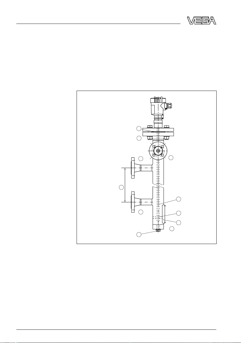
Features and fittings of
the bypass tube
1 Produc
t description
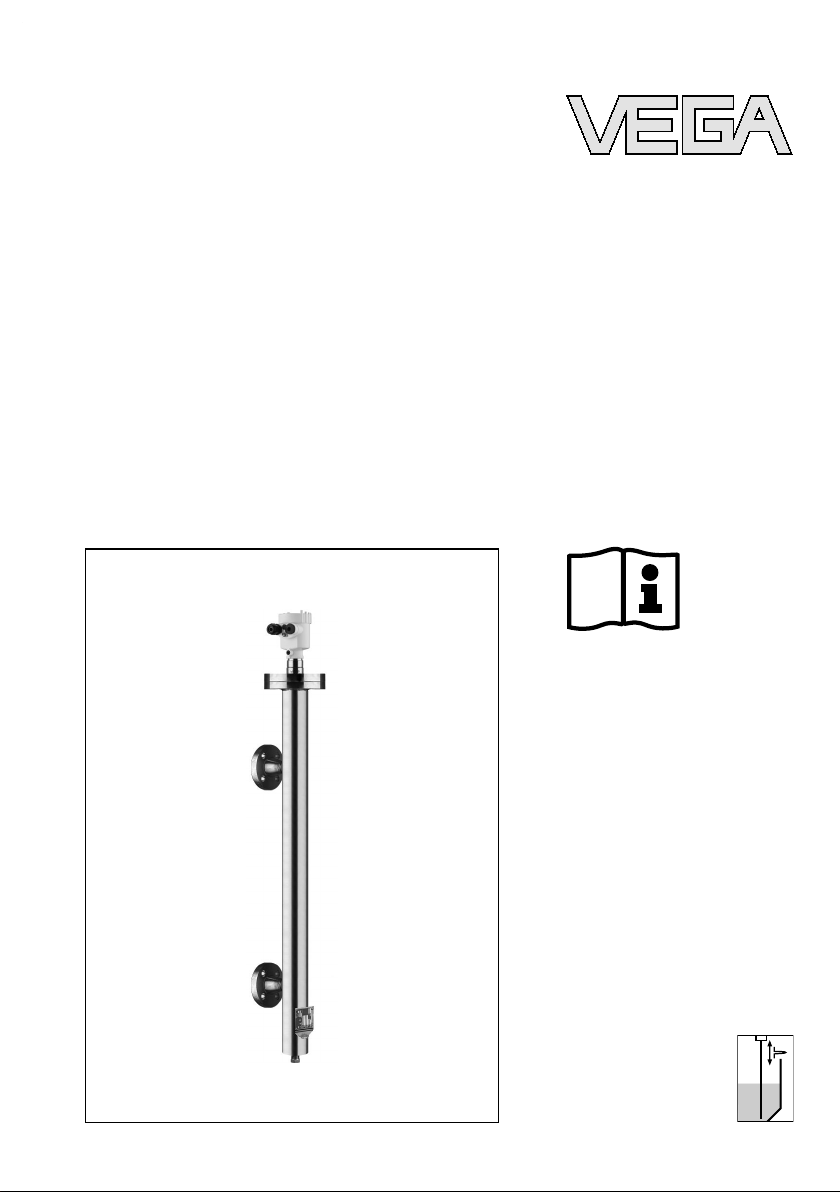
Bypass 72 is a complete level measuring system in a bypass tube,
complete with VEGAFLEX sensor.
Bypass 72 with VEGAFLEX sensor is immediately ready for operation
and requires no adjustment.
Depending on the process pressure or process temperature,
VEGAFLEX 61 and VEGAFLEX 66 sensors can be used in
combination with the bypass tube.
tube with VEGAFLEX
Fig. 1: Bypass
1 Dimensions tube center to tube center, 300 … 3000 mm (11.8 … 118 in)
2 Seal - measuring instrument flange
3 Electrode rod
4 Spacer
5 Type label
6 Closure rinsing connection, e.g. blind stopper
A Measuring instrument flange
B Connection flange, top
C Connection flange, bottom
D Rinsing air connection
E Ventilation connection - optional
2 Bypass 72 • with VEGAFLEX level
33545-EN-081216
sensor
Page 3

2 M
ounting
Operating instructions
Seals
2 Moun
Take note of the attached mounting instructions and the operating
instructions manual of the corresponding VEGAFLEX level sensor.
The seals for the connection flanges and ventilation fitting (optional)
must be provided by the customer.
The seal on the measuring instrument flange (A) and the rinsing
connection (D) are already mounted ex works.
Before use, check if the seal material is resistant against the medium,
the process pressure and the process temperature.
The max. permissible pressure of the sensor is specified in the
operating instructions manual of the sensor in chapter "Technical data"
or on the type label of the sensor.
ting
33545-EN-081216
Bypass 72 • with VEGAFLEX level
sensor 3
Page 4

3 Suppl
ement
3 Supp
lement
3.1 Technical data
General data
Take note of the information in the operating instructions manual of the installed VEGAFLEX level
sensor
Material 316L corresponds to 1.4404 or 1.4435
Materials
- Bypass tube 316L
- Spacer ≤ 250 °C PEEK
- Spacer > 250 °C (optional) 302 (1.4310)
- Seal - Measuring instrument flange
(standard)
- Seal - Measuring instrument flange
(higher pressure stages)
- Seal - Measuring instrument flange
(high temperature/high pressure)
Diameter ø 60.3 mm (2.37 in)
Wall thickness
- Standard version 2 mm (0.079 in)
- High pressure version 3.91 mm (0.154 in)
Volume - bypass tube See following diagram
Klingersil C-4500
Convex B45A graphite laminate
RTJ seal rings
4 Bypass 72 • with VEGAFLEX level
33545-EN-081216
sensor
Page 5

1
2
B
A
4
(1,056)
3
(0,793)
2
(0,528)
1
(0,264)
5
(1,321)
6
(1,585)
7
(1,849)
8
(2,113)
2500 (98
7
/
16
")
3000 (118
1
/
8
")
2000 (78
3
/
4
")
1500 (59
1
/
16
")
500
(19
5
/
8
")
1000 (39
3
/
8
")
0%
100%
0
3 Sup
plement
Fig. 2: Volume
of the bypass tube
1 Tube length in mm (in)
2 Volume in L (US.liq.gal)
A Standard version
B High pressure version
Process temperature see process fitting - connection flange (B,C)
Process pressure see process fitting - connection flange (B,C)
Process fitting - Measuring instrument flange (A)
DN 50 PN 40, Form C, DIN 2501
Flange 2" 300 lb RF, ANSI B16.5
Process fitting - connection flange top/bottom (B, C)
Process pressure in bar (psig) depending on the process temperature
Process temperature 150 °C (302 °F)
Flanges Process pressure Seal Wall thickness
Flange DN 20 PN 40, Form C,
DIN 2501
Flange DN 25 PN 40, Form C,
DIN 2501
Flange DN 50 PN 40, Form C,
DIN 2501
33545-EN-081216
Bypass 72 • with VEGAFLEX level
12 bar (174 psig)/31 bar (450 psig) Klingersil 2 mm (0.079 in)
12 bar (174 psig)/31 bar (450 psig) Klingersil 2 mm (0.079 in)
12 bar (174 psig)/31 bar (450 psig) Klingersil 2 mm (0.079 in)
sensor 5
Page 6

3 Suppl
ement
Flanges Process
Flange 1" 150 lb RF, ANSI B16.5 12 bar (174 psig) Klingersil 2 mm (0.079 in)
Flange 1" 300 lb RF, ANSI B16.5 12 bar (174 psig)/31 bar (450 psig) Klingersil 2 mm (0.079 in)
Flange 2" 150 lb RF, ANSI B16.5 12 bar (174 psig) Klingersil 2 mm (0.079 in)
Flange 2" 300 lb RF, ANSI B16.5 12 bar (174 psig)/31 bar (450 psig) Klingersil 2 mm (0.079 in)
Flange 2" 1500 lb RF, ANSI B16.5 128 bar (1856 psig) RTJ seal ring 3.91 mm (0.154 in)
Flange 2" 1500 lb RJF, ANSI B16.5 128 bar (1856 psig) RTJ seal ring 3.91 mm (0.154 in)
pressure Seal Wall thickness
Process temperature 250 °C (482 °F)
Flanges Process pressure Seal Wall thickness
Flange DN 20 PN 40, Form C,
DIN 2501
Flange DN 25 PN 40, Form C,
DIN 2501
Flange DN 50 PN 40, Form C,
DIN 2501
Flange 1" 150 lb RF, ANSI B16.5 10.5 bar (152 psig) Klingersil 2 mm (0.079 in)
Flange 1" 300 lb RF, ANSI B16.5 10.5 bar (152 psig)/27 bar
Flange 2" 150 lb RF, ANSI B16.5 10.5 bar (152 psig) Klingersil 2 mm (0.079 in)
Flange 2" 300 lb RF, ANSI B16.5 10.5 bar (152 psig)/27 bar
Flange 2" 1500 lb RF, ANSI B16.5 111 bar (1610 psig) RTJ seal ring 3.91 mm (0.154 in)
Flange 2" 1500 lb RJF, ANSI B16.5 111 bar (1610 psig) RTJ seal ring 3.91 mm (0.154 in)
10.5 bar (152 psig)/27 bar
(391 psig)
10.5 bar (152 psig)/27 bar
(391 psig)
10.5 bar (152 psig)/27 bar
(391 psig)
(391 psig)
(391 psig)
Klingersil 2 mm (0.079 in)
Klingersil 2 mm (0.079 in)
Klingersil 2 mm (0.079 in)
Klingersil 2 mm (0.079 in)
Klingersil 2 mm (0.079 in)
Process temperature 400 °C (752 °F)
Flanges Process pressure Seal Wall thickness
Flange DN 20 PN 40, Form C,
DIN 2501
Flange DN 25 PN 40, Form C,
DIN 2501
Flange DN 50 PN 40, Form C,
DIN 2501
Flange 1" 150 lb RF, ANSI B16.5 6.5 bar (94 psig) graphite 2 mm (0.079 in)
Flange 1" 300 lb RF, ANSI B16.5 6.5 bar (94 psig)/24 bar (348 psig) graphite 2 mm (0.079 in)
Flange 2" 150 lb RF, ANSI B16.5 6.5 bar (94 psig) graphite 2 mm (0.079 in)
Flange 2" 300 lb RF, ANSI B16.5 6.5 bar (94 psig)/24 bar (348 psig) graphite 2 mm (0.079 in)
6 Bypass 72 • with VEGAFLEX level
6.5 bar (94 psig)/24 bar (348 psig) graphite 2 mm (0.079 in)
6.5 bar (94 psig)/24 bar (348 psig) graphite 2 mm (0.079 in)
6.5 bar (94 psig)/24 bar (348 psig) graphite 2 mm (0.079 in)
33545-EN-081216
sensor
Page 7

3 Sup
plement
Flanges Process
Flange 2" 1500 lb RF, ANSI B16.5 95 bar (1378 psig) RTJ seal ring 3.91 mm (0.154 in)
Flange 2" 1500 lb RJF, ANSI B16.5 95 bar (1378 psig) RTJ seal ring 3.91 mm (0.154 in)
pressure Seal Wall thickness
Process fitting - Rinsing air connection (D)
Thread G½
½ NPT
Process fitting - Ventilation fitting (E) (optional)
Flange DN 15 PN 40
Flange ½" 1500 lb RF, ANSI B16.5
33545-EN-081216
Bypass 72 • with VEGAFLEX level
sensor 7
Page 8

115 mm
(4.53")
0 %
100 %
ø 60,3 mm
(2.37")
140 mm
(5.51")
150 mm (5.91")
250 mm (9.84")
100 mm
(3.94")
E
D
C
B
A
1
2
4
5
3
6
3 Suppl
3.2 D
ement
imensions
Fig. 3: Bypass
1 Dimensions tube center to tube center, 300 … 3000 mm (11.8 … 118 in)
2 Seal - measuring instrument flange
3 Electrode rod
4 Spacer
5 Type label
6 Closure rinsing connection, e.g. blind stopper
A Measuring instrument flange
B Connection flange, top
C Connection flange, bottom
D Rinsing air connection
8 Bypass 72 • with VEGAFLEX level
tube with VEGAFLEX
33545-EN-081216
sensor
Page 9

3 Sup
plement
E Ventilation
connection - optional
33545-EN-081216
Bypass 72 • with VEGAFLEX level
sensor 9
Page 10

3 Suppl
ement
10 Bypass 72 • with VEGAFLEX level
33545-EN-081216
sensor
Page 11

3 Sup
plement
33545-EN-081216
Bypass 72 • with VEGAFLEX level
sensor 11
Page 12

VEGA Grieshaber KG
ISO 9001
Am Hohenstein 113
77761 Schiltach
Germany
Phone +49 7836 50-0
Fax +49 7836 50-201
E-mail: info@de.vega.com
www.vega.com
Printing date:
statements concerning scope of delivery, application,
All
practical use and operating conditions of the sensors and
processing systems correspond to the information avail-
able at the time of printing.
© VEGA Grieshaber KG, Schiltach/Germany 2008
Subject to change without prior notice 33545-EN-081216
 Loading...