

Page 1
www.vega-absolute.ru
GATEWAY
VEGA BS
User Manual
VEGA BS gateway is designed to deploy LoRaWAN network
within 863-870 MHz frequency band.
VEGA BS operates with Linux operating system and is supplied
with pre-installed Packet forwarder software.
Page 2

Vega BS/User Manual
2
Revision 10 – 02 November 2017
Document Information
Title
Gateway VEGA BS
Document type
Manual
Document number
V02-BS-01
Revision and date
10 - 02 November 2017
This document applies to the following products:
Product name
Type number
VEGA BS
VEGA BS-1
VEGA BS-2
Revision History
Revision
Date
Name
Comments
01
27.04.2017
KEV
Document creation date
02
15.05.2017
PKP
Minor edits
03
18.05.2017
KEV
Общее руководство на БС-1 и БС-2
04
13.06.2017
KEV
Edits in the content of the package
05
14.06.2017
KEV
Part «Configuration» was edit, A5 format
06
14.08.2017
KEV
Antenna mounting recommendation was added
07
16.08.2017
KEV
Part «Operation» was edit
08
28.08.2017
KEV
Minor edits in the «Configuration of a static IP-adress»
09
27.09.2017
KEV
«SIM card installation» was added
10
02.11.2017
KEV
Parts «BS-2 configuring for 3G work», «Recommendations»
were added, new format
Page 3

Vega BS/User Manual
3
Revision 10 – 02 November 2017
CONTENT
INTRODUCTION ............................................................................................................................................................................ 4
1 DESCRIPTION AND OPERATION PRINCIPLES ...................................................................................................................... 5
2 SPECIFICATION .......................................................................................................................................................................... 6
3 OPERATION ................................................................................................................................................................................. 7
Contacts ...................................................................................................................................................................................... 8
Input and output interfaces ..................................................................................................................................................... 9
SIM card installation at the BS-2 ........................................................................................................................................... 10
Control instruments – pushbuttons and switches ........................................................................................................... 11
Indication .................................................................................................................................................................................. 11
4 GATEWAY CONFIGURATION ................................................................................................................................................ 13
Connection to the computer – start of work .................................................................................................................... 13
Packet forwarder updating to 4.0.1 version ....................................................................................................................... 19
Configuration of a static IP-adress for the gateway ......................................................................................................... 20
Gateway setting up for 3G operation .................................................................................................................................. 23
5 STORAGE AND TRANSPORTATION REQUIREMENTS ...................................................................................................... 26
6 CONTENT OF THE PACKAGE ................................................................................................................................................ 27
7 WARRANTY ................................................................................................................................................................................ 28
Appendix – recommendations for working with gateway ................................................................................................. 29
Antenna mounting recommendations ................................................................................................................................ 29
Recommendations for gateway using in white IP net ..................................................................................................... 30
Page 4

Vega BS/User Manual
4
Revision 10 – 02 November 2017
INTRODUCTION
This manual is designated for VEGA BS-1 and VEGA BS-2 gateways (hereinafter – the
gateway) manufactured by LLC Vega-Absolute and provides information on powering and
activation procedure, control commands and functions of the gateway.
This manual is targeted at specialists familiar with installation work fundamentals for
electronic and electrical equipment.
The gateway shall be installed and adjusted by qualified specialists in order
to ensure proper operation of the device.
Page 5

Vega BS/User Manual
5
Revision 10 – 02 November 2017
1 DESCRIPTION AND OPERATION PRINCIPLES
VEGA BS gateway is designed to deploy LoRaWAN network within 863-870 MHz
frequency band.
The gateway operates with Linux operating system and is supplied with pre-installed
Packet forwarder software.
Fig. 1.1 Appearance of VEGA BS gateway
The gateway is powered and communicates with the server via the Ethernet channel.
The device is configured through Ethernet via SSH protocol with any terminal program
(e.g. PuTTY).
VEGA BS-2 has an additional 3G-module for communication channel and
GPS/GLONASS-module for gateway positioning, and internal clock synchronizing with
navigation-satellites signals.
Page 6

Vega BS/User Manual
6
Revision 10 – 02 November 2017
2 SPECIFICATION
BS-1
BS-2
Main
GPS/GLONASS module
no
yes
3G modem
no
yes
Server communication link
Ethernet
Ethernet, GSM 3G
Operating system
Linux
USB-port
yes
Operating temperatures
-40…+85 °С
LoRaWAN
Number of LoRa channels
8
Frequency band
863-870 MHz
Power output
up to 500 mW
Antenna connector
SMA
Radio coverage in restrained urban conditions
up to 5 km
Radio coverage within line of sight
up to 15 km
Power
Power consumption
3 W
4 W
Power supply
Passive POE 4,5(+) 7,8(-) 15 W
Case
Housing dimensions
165 х 110 х 40 mm
Ingress protection rating
IP65
Mounting
mast supports
Page 7
Vega BS/User Manual
7
Revision 10 – 02 November 2017
3 OPERATION
The gateway terminal board has control and indication instruments, input and output
interfaces. Detailed information see below.
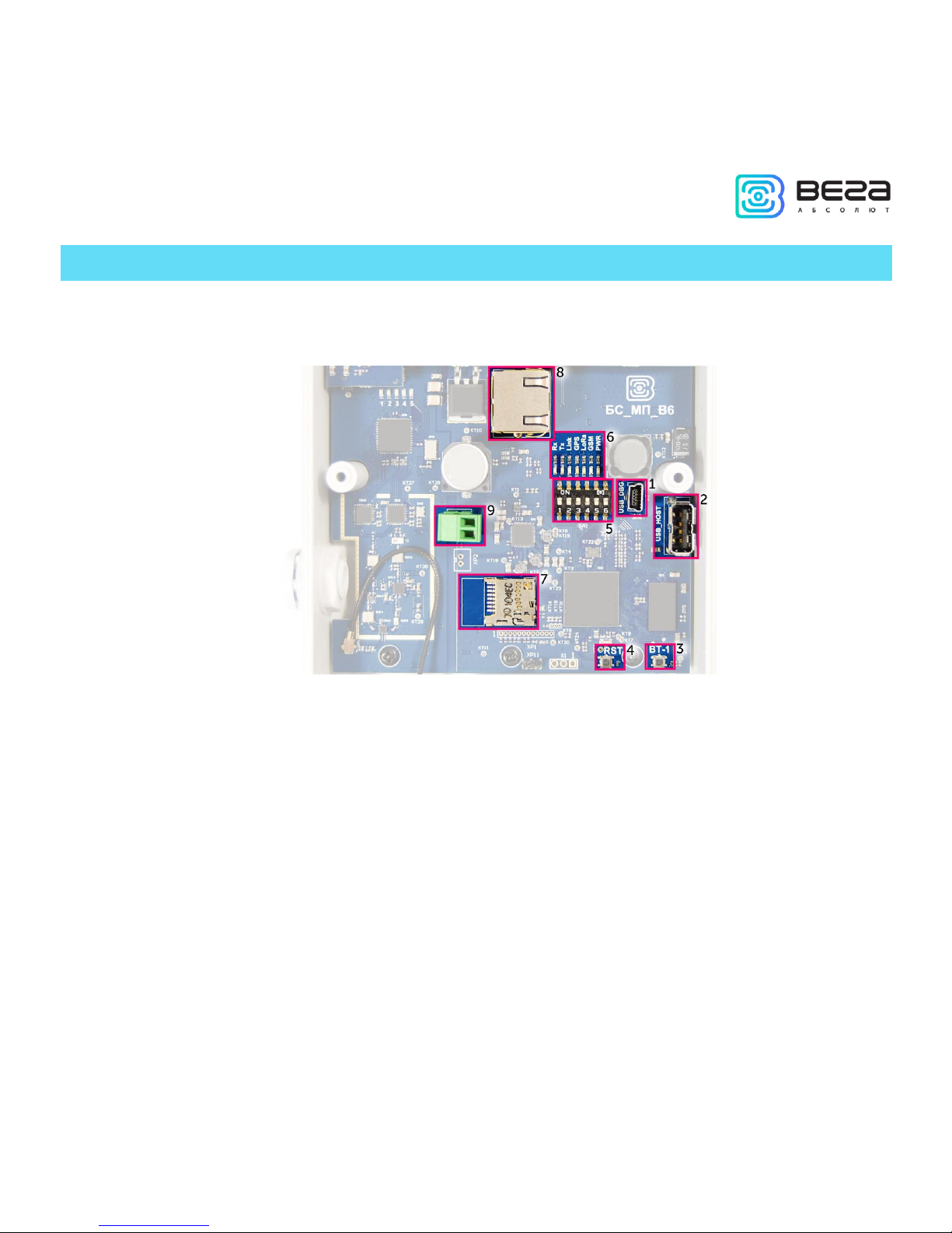
Fig. 3.1. Control and indication instruments, input and output interfaces.
1 – mini USB-port for connection to a computer
2 – USB-host for connection of external devices
3
– /Spare/
4 – gateway reset button
5 – service DIP-switches
6 – performance indicators of various systems
7 – micro SD-card connector
8 – Ethernet-cable connector
9 – additional power connector (optional)
Page 8

Vega BS/User Manual
8
Revision 10 – 02 November 2017
CONTACTS
Fig. 3.2. Contacts in the connectors.
The gateway is connected to the network with 8-core network cable (twisted pair)
through connector on the terminal board (fig. 3.1 (8)). Cable shall be crimped in compliance
with Т568А and Т568B standards. Contacts shall be numerated 1-8 right-to-left.
Colors are shown for cable T568B:
Contact no.
Color
Designation
1
Orange-and-white
TD+ signal
2
Orange
TD- signal
3
Green-and-white
RD+ signal
4
Blue
Power
5
Blue-and-white
Power
6
Green
RD- signal
7
Brown-and-white
Ground
8
Brown
Ground
Page 9
Vega BS/User Manual
9
Revision 10 – 02 November 2017
There is an additional power connector on the board (fig. 3.1 (9)). It can be connected
only when power contacts 4, 5 and 7, 8 in the network cable are disabled. Permissible power
voltage is 12-48 V. Minimum power is 20 W.
INPUT AND OUTPUT INTERFACES
The gateway has a mini-USB-port for connecting to a computer and working via the
SSH protocol (Fig. 3.1 (1)), and a USB-host for connecting of external devices via a USB cable
(Fig. 3.1 (2)). There is a slot on the board for a SD card (fig. 3.1 (7)).
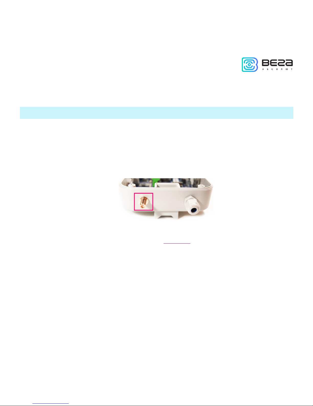
In addition, there is a SMA socket on the gateway housing for connecting of the
antenna supplied with the device.
For high-quality signal reception, it is important to properly place the gateway antenna.
For antenna installing recommendations, see the Appendix.
Page 10
Vega BS/User Manual
10
Revision 10 – 02 November 2017
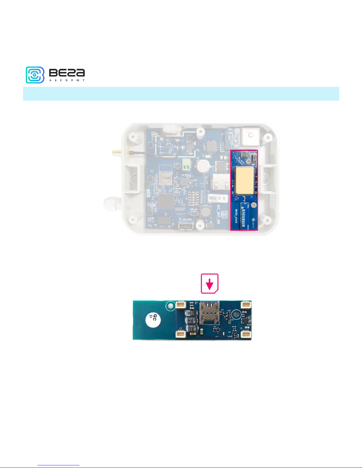
SIM CARD INSTALLATION AT THE BS-2
The Vega BS-2 gateway includes a GSM module, which is installed on the main board.
The SIM slot is located on the back of the module. To install the SIM card, you must
disconnect the GSM module from the main board and turn it over.
The SIM card of the micro-SIM format is inserted into the slot, after which the GSM
module is replaced.
Page 11

Vega BS/User Manual
11
Revision 10 – 02 November 2017
CONTROL INSTRUMENTS – PUSHBUTTONS AND SWITCHES
There are two buttons on the gateway board. One button is spare for further
developments (Fig. 3.1 (3)). Push the other button (Fig. 3.1 (4)) for the gateway instantaneous
rebooting.
In addition, there are DIP switches (Fig. 3.1 (5)) on the board used to select the
download option of the firmware image: from internal memory, from the SD card or via miniUSB from the computer. The switches are used only in service conditions. In operating mode,
only switches 3 and 4 shall be enabled, see fig. 3.3.
Fig. 3.3. Operating position of DIP-switches
INDICATION
There are several LEDs (fig. 3.1 (6)) on the terminal board, which signals are shown in
the table below. They indicate operation of particular systems: power (on / off), visibility of
GPS satellites, GSM modem (on / off), operation of the LoRa signal processing program
(Packet forwarder on/off), Ethernet activity, the data exchange via mini USB port.
Page 12

Vega BS/User Manual
12
Revision 10 – 02 November 2017
LED
Color
Indication
Rx
Green
Flashes
– data exchange via USB_DBG port
Tx
Red
Link
Green
Flashes
– activity via Ethernet
GPS1
Blue
Doesn’t light
– no data from GPS-receiver
Flashes
– there data exist, but are not valid for use by Packet
forwarder
Lights –
location identified
LoRa
Yellow
Lights
– Packet forwarder is started
Doesn’t light
– Packet forwarder is stopped
GSM
Green
Lights
– GSM-modem is enabled
Doesn’t light
– GSM-modem is disabled
PWR
Red
Lights
– gateway is powered
Doesn’t light
– gateway is not powered
1
GPS LED indicates GPS system functioning only when Packet forwarder is started (LoRa LED lights).
Page 13

Vega BS/User Manual
13
Revision 10 – 02 November 2017
4 GATEWAY CONFIGURATION
CONNECTION TO THE COMPUTER – START OF WORK
The gateway is configured when connected to a computer using a terminal program.
Connection is possible, for example, with a mass-market PuTTY program. There are two ways
of connection to the gateway – via a serial port or SSH.
1. Connection via a serial port
In case of a serial port, connect the gateway to a personal computer with a mini-USB
connector by a cable. On the board, the required port is designated as USB_DBG (Fig. 3.1 (1)).
Next, connect to a virtual COM port by installing the driver for MCP2200. "Ports (COM and
LPT)" menu appears at the device manager.
Search “USB Serial Port” in the “Ports” menu and see its number.
Page 14

Vega BS/User Manual
14
Revision 10 – 02 November 2017
Open PuTTY, select Serial, enter number of the gateway virtual COM-port and speed
(115200) in the corresponding fields.
Page 15

Vega BS/User Manual
15
Revision 10 – 02 November 2017
Push “Open” button.
2. Connection via SSH
In case of SSH, select SSH connection in the PuTTY dialog box, enter the device's IPaddress and port 22. By default, the device obtains an IP-address via DHCP when connected
via Ethernet.
Page 16

Vega BS/User Manual
16
Revision 10 – 02 November 2017
Push “Open” button.
After connecting to the gateway by one of the methods, PuTTY terminal window
appears, where login and password shall be entered. By default, login root and password
temppwd are used for connection to the gateway. At the first connection, it is recommended
to change the password for individual access.
Page 17

Vega BS/User Manual
17
Revision 10 – 02 November 2017
Now the configuration can be carried out.
Packet forwarder starts automatically when the system starts. Before the gateway
configuring, stop Packet forwarder by entering command:
/etc/init.d/lora_watchdog stop
Configuration files are in the directory LoRa/packet_forwarder/lora_pkt_fwd – it may
contain frequency band, the gateway ID, IP-address and server ports settings.
global_conf.json – global configuration file;
Page 18

Vega BS/User Manual
18
Revision 10 – 02 November 2017
local_conf.json – local configuration file.
Settings contained in local_conf.json file take priority over global_conf.json
Enter the command, containing the required configuration file in order to change the
settings, for example:
After all changes completed enter the command:
/etc/init.d/lora_watchdog start
Packet forwarder will automatically start with new settings.
Page 19

Vega BS/User Manual
19
Revision 10 – 02 November 2017
PACKET FORWARDER UPDATING TO 4.0.1 VERSION
Packet forwarder updating is carried out when connected to a computer using the
terminal program as follows:
1. After connecting to the gateway enter login and password in the PuTTY terminal
window.
2. Enter a command /etc/init.d/lora_watchdog stop – command to turn off the
internal timer.
3. Go to the root directory with the command cd ~/
Before upgrading Packet forwarder, save the settings from the files
local_conf.json and global_conf.json located in ~/LoRa/packet_forwarder
/lora_pkt_fwd/ for later restoration of the settings after the update
4. Delete files of the previous version of Packet forwarder by sequential introduction
of commands:
rm -r LoRa
rm LoRa.tar.gz
5. Download files of the new version of the Packet forwarder by typing at the
command line:
wget ftp://89.189.183.233:14104/3.12.10-ti2013.12.01/LoRa_v4.0.1.tar.gz
6. Unzip the downloaded files with the command tar xf LoRa_v4.0.1.tar.gz -C ~/
7. Move downloaded files to the working directory mv ~/LoRa_v4.0.1 ~/LoRa
8. Restore settings in files local_conf.json и global_conf.json
9. If the GPS module "MOD_EVA" is used in BS-2, then in the file global_conf.json the
option "ubx_timegps_control_enable" should be enabled, i.e.
"Ubx_timegps_control_enable": true. In other cases, when the GPS-module is called
otherwise, this option should be turned off, i.e. "Ubx_timegps_control_enable":
false.
Page 20

Vega BS/User Manual
20
Revision 10 – 02 November 2017
10. Restart the Packet forwarder process with the command
/etc/init.d/lora_watchdog start
Update complete.
CONFIGURATION OF A STATIC IP-ADRESS FOR THE GATEWAY
Configuration of a static IP shall be carried out with the terminal program:
1. After connecting to the gateway enter login and password in the PuTTY terminal
window.
Page 21

Vega BS/User Manual
21
Revision 10 – 02 November 2017
2. Open file /etc/network/interfaces. Search authorization settings in this file:
3. Enter changes highlighted in red (example: static IP address 192.168.240.252 and
gateway 192.168.240.1):
auto eth0
iface eth0 inet static
pre-up /bin/grep -v -e "ip=[0-9]\+\.[0-9]\+\.[0-9]\+\.[0-9]\+" /proc/cmdline > /dev/null
address 192.168.240.252
netmask 255.255.255.0
gateway 192.168.240.1
4. Open file ~/link_detect.sh, then search string
if [ "$LINK_STATE" == "UP" ] ; then
Page 22

Vega BS/User Manual
22
Revision 10 – 02 November 2017
Check, that after this string the following string is entered
if [ -n "$(cat /etc/network/interfaces | grep "iface $INTERFACE inet dhcp")" ]; then
Check, that before string
killall -15 lora_pkt_fwd
the following string is entered
fi
(see figure below)
5. If the strings correspond to the figure above, do not change anything. If these
strings are absent, enter them – changes are highlighted in red:
if [ "$LINK_STATE" == "UP" ] ; then
if [ -n "$(cat /etc/network/interfaces | grep "iface $INTERFACE inet dhcp")" ]; then
killall -15 udhcpc
Page 23

Vega BS/User Manual
23
Revision 10 – 02 November 2017
udhcpc –R –t 5 –n –p /var/run/udhcpc.$INTERFACE.pid –i $INTERFACE
fi
killall -15 lora_pkt_fwd
6. Enter reboot at the command line to reboot the gateway with new settings.
GATEWAY SETTING UP FOR 3G OPERATION
Gateway setting up for 3G operation using the terminal program is carried out in the
following order:
1. After connecting to the gateway enter login and password in the PuTTY terminal
window.
2. Check, that in file /etc/ppp/peers/wvdial entered strings highlighted in red:
noauth
name wvdial
usepeerdns
defaultroute
replacedefaultroute
If these strings are not present, then they should be added.
3. Check, that in file /etc/wvdial.conf entered strings highlighted in red:
; Init1 = ATZ
; Init2=ATQO V1 E1 &C1 &D2 +FCLASS=0
Init1 = AT+CPIN?
Init2 = AT+CGDCONT=1,"IP","internet.beeline.ru"
Modem Type = USB Modem
Baud = 460800
New PPPD = yes
Auto Reconnect = off
Modem = /dev/ttyACM0
Page 24

Vega BS/User Manual
24
Revision 10 – 02 November 2017
ISDN = 0
Phone = *99#
Password = beeline
Username = beeline
where "internet.beeline.ru" is APN cellular operator.
If the strings correspond to the figure above, you do not need to change anything. If
these strings are not present, then they should be added. At that, strings
Init1 = AT+CPIN?
Init2 = AT+CGDCONT=1,"IP","internet.beeline.ru"
entered instead string
Init = AT+CGDCONT=1,"IP","internet.beeline.ru"
The last three strings of the file specify the required dial-up phone, user name and
password (different for each cellular operator):
Phone = *99#
Password = beeline
Username = beeline
4. Create a script to update the DNS data received from the operator
nano /etc/ppp/ip-up.d/resolv_conf_update
#!/bin/sh -e
cat /etc/ppp/resolv.conf > /etc/resolv.conf
exit 0
Give him the right to run by typing at the command line:
chmod +x /etc/ppp/ip-up.d/resolv_conf_update
Page 25

Vega BS/User Manual
25
Revision 10 – 02 November 2017
5. Add parameters to startup by typing at the command line:
update-rc.d gsm_init defaults
6. Type reboot at the command line to reboot the gateway with new settings.
To stop using the 3G modem for communicate with server, type at the command line
update-rc.d -f gsm_init remove and restart the gateway to apply new settings.
To start using the 3G modem to communicate with the server again, type update-rc.d
gsm_init defaults at the command line and restart the gateway to apply new settings.
For recommendations for gateways using white IP, see Appendix.
Page 26

Vega BS/User Manual
26
Revision 10 – 02 November 2017
5 STORAGE AND TRANSPORTATION REQUIREMENTS
VEGA BS gateways shall be stored in the original packaging in heated room at
temperatures +5°С to +40°С and relative humidity less than 85%.
The gateway shall be transported in covered freight compartments of all types at any
distance at temperatures -40°C to +85°C.
Page 27

Vega BS/User Manual
27
Revision 10 – 02 November 2017
6 CONTENT OF THE PACKAGE
The gateway is delivered complete with:
VEGA BS gateway – 1 pce.
Antenna 864-870 MHz– 1 pce.
POE-adapter– 1 pce.
Data sheet – 1 pce.
Page 28

Vega BS/User Manual
28
Revision 10 – 02 November 2017
7 WARRANTY
The manufacturer guarantees normal operation of the gateway and its elements within
36 months from the date of sale.
The manufacturer undertakes to repair or replace the failed device within 36 months
from the date of sale.
The consumer undertakes to comply with the terms and conditions of transportation,
storage and operation, specified in this manual.
Warranty does not apply to:
- the device with mechanical, electrical and / or other damages and defects caused by
violation of the transportation, storage and operation requirements;
- the device lacking any part of the kit;
- the device with traces of repair performed not by the manufacturer's service center;
- the device with traces of oxidation or other signs of liquids leaking inside the device.
In the event of a warranty claim, contact the service center:
113/1, Kirova Str., Novosibirsk, 630008, Russia.
Tel.: +7 (383) 206-41-35.
Page 29

Vega BS/User Manual
29
Revision 10 – 02 November 2017
APPENDIX – RECOMMENDATIONS FOR WORKING WITH GATEWAY
ANTENNA MOUNTING RECOMMENDATIONS
The Antenna included in the scope of supply has fasteners for installation on a mast
support. To ensure maximum communication range, follow the installation guidelines for the
antenna:
1. Install the antenna outside, preferably on the roof of the building (the higher - the
better, depending on the surrounding buildings). Installing the antenna in the room
significantly weakens the sensitivity of the antenna.
2. The installation site shall be as far as possible from the cellular antennas. Antenna
tuning requires the maximum distance from other antennas. After tuning and testing, antenna
can be brought back closer to the cellular antennas, if the quality of the communication is
satisfactory.
3. The antenna shall not stand in the close proximity to obstacles (about 2 meters from
railing, walls, etc.). The sensitivity towards the obstacle weakens.
4. The gateway shall be installed in the close proximity to the antenna – at the length of
the antenna coaxial conductor. Increase of the cable length between the antenna and the
gateway will result in a loss of antenna sensitivity.
For example, 25 meters of RG-58 cable attenuate the signal by 14 dBm, i.e. if
transmission power is 14 dBm (25mW), the power on the antenna will be
1mW
5. The antenna directional pattern shall be taken into account. In the horizontal plane,
the antenna has a circular direction, but no vertical direction. Therefore, the quality of
communication directly under the antenna will be worse than at some distance from the
antenna.
Page 30

Vega BS/User Manual
30
Revision 10 – 02 November 2017
RECOMMENDATIONS FOR GATEWAY USING IN WHITE IP NET
In case the BS is used in network with white IP, it is recommended to change the
standard port numbers of ssh and telnet to anothers. This should be taken into account while
port forwarding. The steps sequence for changing BS dropbear and telnetd ports is described
below.
To change ssh port:
1. Enter at the command line of the terminal program /etc/init.d/dropbear stop
2. Open file nano /etc/init.d/dropbear
3. Find string DROPBEAR_PORT=22 and change standard port «22» to another, then
save the file.
4. Enter at the command line of the terminal program /etc/init.d/dropbear start
Page 31

Vega BS/User Manual
31
Revision 10 – 02 November 2017
To change telnet port:
1. Enter at the command line of the terminal program /etc/init.d/telnetd stop
2. Enter at the command line killall -15 telnetd
3. Open file nano /etc/init.d/telnetd - and find strings:
4. Enter strings highlighted in red (instead of "2224" enter the desired port number):
telnetd=/usr/sbin/telnetd
port="-p 2224"
...
start-stop-daemon --start --quiet --exec $telnetd -- $port
5. Save file and enter at the command line /etc/init.d/telnetd start
Page 32

Vega BS/User Manual
32
Revision 10 – 02 November 2017
vega-absolute.ru
User Manual © LLC Vega-Absolute 2017
 Loading...