

Vega BS-1, BS-2 User Manual
www.vega-absolute.ru
GATEWAY
VEGA BS
User Manual
VEGA BS gateway is designed to deploy LoRaWAN network
within 863-870 MHz frequency band.
VEGA BS operates with Linux operating system and is supplied
with pre-installed Packet forwarder software.

Vega BS/User Manual
2
Revision 10 – 02 November 2017
Document Information
Title
Gateway VEGA BS
Document type
Manual
Document number
V02-BS-01
Revision and date
10 - 02 November 2017
This document applies to the following products:
Product name
Type number
VEGA BS
VEGA BS-1
VEGA BS-2
Revision History
Revision
Date
Name
Comments
01
27.04.2017
KEV
Document creation date
02
15.05.2017
PKP
Minor edits
03
18.05.2017
KEV
Общее руководство на БС-1 и БС-2
04
13.06.2017
KEV
Edits in the content of the package
05
14.06.2017
KEV
Part «Configuration» was edit, A5 format
06
14.08.2017
KEV
Antenna mounting recommendation was added
07
16.08.2017
KEV
Part «Operation» was edit
08
28.08.2017
KEV
Minor edits in the «Configuration of a static IP-adress»
09
27.09.2017
KEV
«SIM card installation» was added
10
02.11.2017
KEV
Parts «BS-2 configuring for 3G work», «Recommendations»
were added, new format

Vega BS/User Manual
3
Revision 10 – 02 November 2017
CONTENT
INTRODUCTION ............................................................................................................................................................................ 4
1 DESCRIPTION AND OPERATION PRINCIPLES ...................................................................................................................... 5
2 SPECIFICATION .......................................................................................................................................................................... 6
3 OPERATION ................................................................................................................................................................................. 7
Contacts ...................................................................................................................................................................................... 8
Input and output interfaces ..................................................................................................................................................... 9
SIM card installation at the BS-2 ........................................................................................................................................... 10
Control instruments – pushbuttons and switches ........................................................................................................... 11
Indication .................................................................................................................................................................................. 11
4 GATEWAY CONFIGURATION ................................................................................................................................................ 13
Connection to the computer – start of work .................................................................................................................... 13
Packet forwarder updating to 4.0.1 version ....................................................................................................................... 19
Configuration of a static IP-adress for the gateway ......................................................................................................... 20
Gateway setting up for 3G operation .................................................................................................................................. 23
5 STORAGE AND TRANSPORTATION REQUIREMENTS ...................................................................................................... 26
6 CONTENT OF THE PACKAGE ................................................................................................................................................ 27
7 WARRANTY ................................................................................................................................................................................ 28
Appendix – recommendations for working with gateway ................................................................................................. 29
Antenna mounting recommendations ................................................................................................................................ 29
Recommendations for gateway using in white IP net ..................................................................................................... 30

Vega BS/User Manual
4
Revision 10 – 02 November 2017
INTRODUCTION
This manual is designated for VEGA BS-1 and VEGA BS-2 gateways (hereinafter – the
gateway) manufactured by LLC Vega-Absolute and provides information on powering and
activation procedure, control commands and functions of the gateway.
This manual is targeted at specialists familiar with installation work fundamentals for
electronic and electrical equipment.
The gateway shall be installed and adjusted by qualified specialists in order
to ensure proper operation of the device.

Vega BS/User Manual
5
Revision 10 – 02 November 2017
1 DESCRIPTION AND OPERATION PRINCIPLES
VEGA BS gateway is designed to deploy LoRaWAN network within 863-870 MHz
frequency band.
The gateway operates with Linux operating system and is supplied with pre-installed
Packet forwarder software.
Fig. 1.1 Appearance of VEGA BS gateway
The gateway is powered and communicates with the server via the Ethernet channel.
The device is configured through Ethernet via SSH protocol with any terminal program
(e.g. PuTTY).
VEGA BS-2 has an additional 3G-module for communication channel and
GPS/GLONASS-module for gateway positioning, and internal clock synchronizing with
navigation-satellites signals.
Vega BS/User Manual
6
Revision 10 – 02 November 2017
2 SPECIFICATION
BS-1
BS-2
Main
GPS/GLONASS module
no
yes
3G modem
no
yes
Server communication link
Ethernet
Ethernet, GSM 3G
Operating system
Linux
USB-port
yes
Operating temperatures
-40…+85 °С
LoRaWAN
Number of LoRa channels
8
Frequency band
863-870 MHz
Power output
up to 500 mW
Antenna connector
SMA
Radio coverage in restrained urban conditions
up to 5 km
Radio coverage within line of sight
up to 15 km
Power
Power consumption
3 W
4 W
Power supply
Passive POE 4,5(+) 7,8(-) 15 W
Case
Housing dimensions
165 х 110 х 40 mm
Ingress protection rating
IP65
Mounting
mast supports
Vega BS/User Manual
7
Revision 10 – 02 November 2017
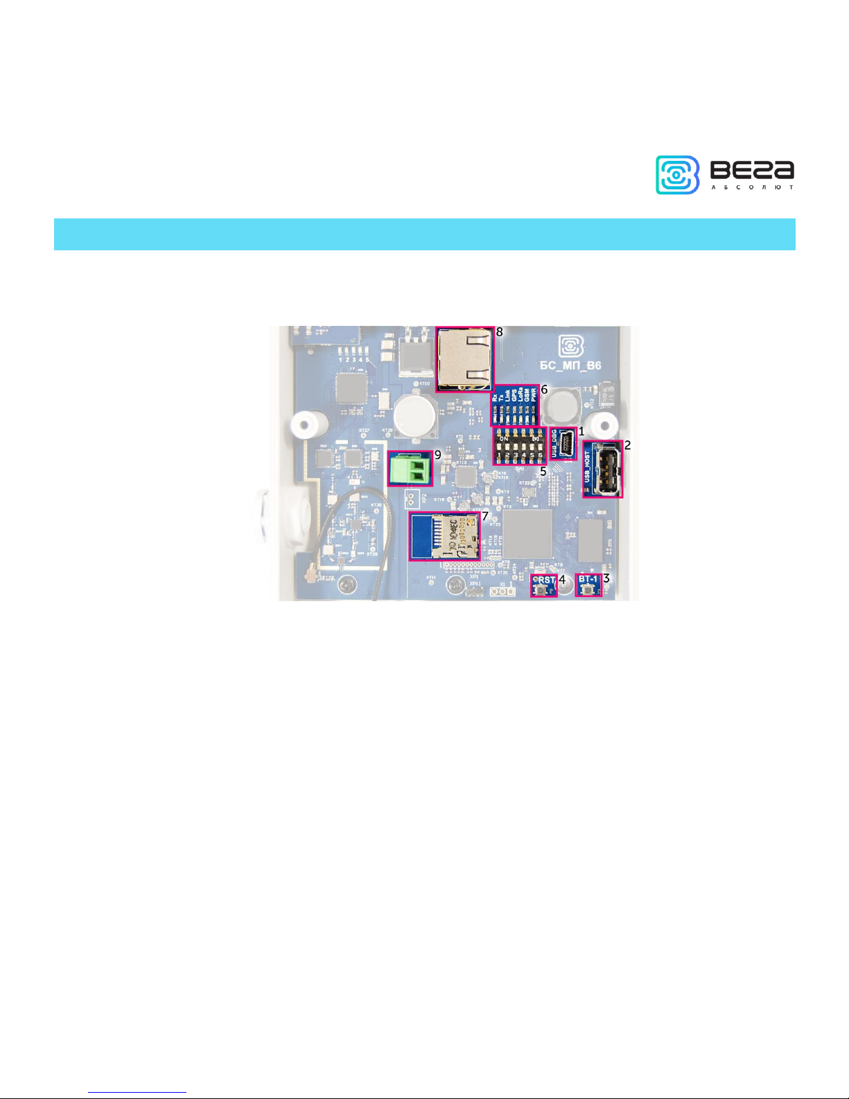
3 OPERATION
The gateway terminal board has control and indication instruments, input and output
interfaces. Detailed information see below.
Fig. 3.1. Control and indication instruments, input and output interfaces.
1 – mini USB-port for connection to a computer
2 – USB-host for connection of external devices
3
– /Spare/
4 – gateway reset button
5 – service DIP-switches
6 – performance indicators of various systems
7 – micro SD-card connector
8 – Ethernet-cable connector
9 – additional power connector (optional)

Vega BS/User Manual
8
Revision 10 – 02 November 2017
CONTACTS
Fig. 3.2. Contacts in the connectors.
The gateway is connected to the network with 8-core network cable (twisted pair)
through connector on the terminal board (fig. 3.1 (8)). Cable shall be crimped in compliance
with Т568А and Т568B standards. Contacts shall be numerated 1-8 right-to-left.
Colors are shown for cable T568B:
Contact no.
Color
Designation
1
Orange-and-white
TD+ signal
2
Orange
TD- signal
3
Green-and-white
RD+ signal
4
Blue
Power
5
Blue-and-white
Power
6
Green
RD- signal
7
Brown-and-white
Ground
8
Brown
Ground
Vega BS/User Manual
9
Revision 10 – 02 November 2017
There is an additional power connector on the board (fig. 3.1 (9)). It can be connected
only when power contacts 4, 5 and 7, 8 in the network cable are disabled. Permissible power
voltage is 12-48 V. Minimum power is 20 W.
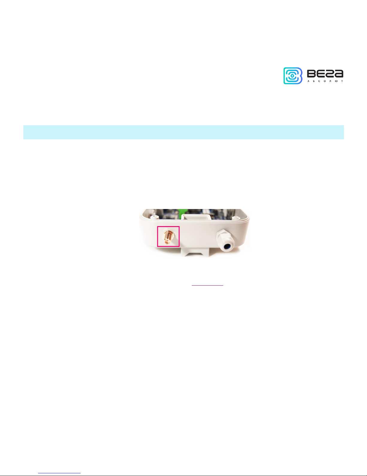
INPUT AND OUTPUT INTERFACES
The gateway has a mini-USB-port for connecting to a computer and working via the
SSH protocol (Fig. 3.1 (1)), and a USB-host for connecting of external devices via a USB cable
(Fig. 3.1 (2)). There is a slot on the board for a SD card (fig. 3.1 (7)).
In addition, there is a SMA socket on the gateway housing for connecting of the
antenna supplied with the device.
For high-quality signal reception, it is important to properly place the gateway antenna.
For antenna installing recommendations, see the Appendix.
Vega BS/User Manual
10
Revision 10 – 02 November 2017
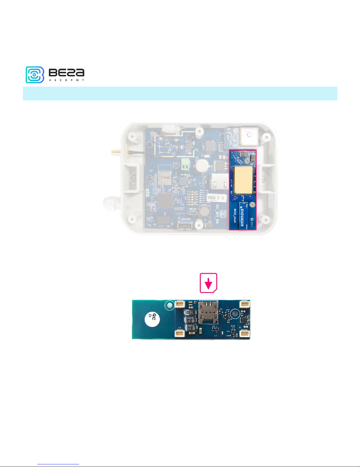
SIM CARD INSTALLATION AT THE BS-2
The Vega BS-2 gateway includes a GSM module, which is installed on the main board.
The SIM slot is located on the back of the module. To install the SIM card, you must
disconnect the GSM module from the main board and turn it over.
The SIM card of the micro-SIM format is inserted into the slot, after which the GSM
module is replaced.
 Loading...