

Page 1

ENGLISH
M1.1 WR
Installation video
Operating video
Settings video
www.vdocyclecomputing.com/service
1
Page 2
Preface
Congratulations
In choosing a VDO computer, you have opted for high-quality
device with first rate technology.
To optimally use the computer, we recommend that you read
this manual carefully. It contains full operating instructions
and many useful tips.
We hope you enjoy cycling with your VDO computer.
Cycle Parts GmbH
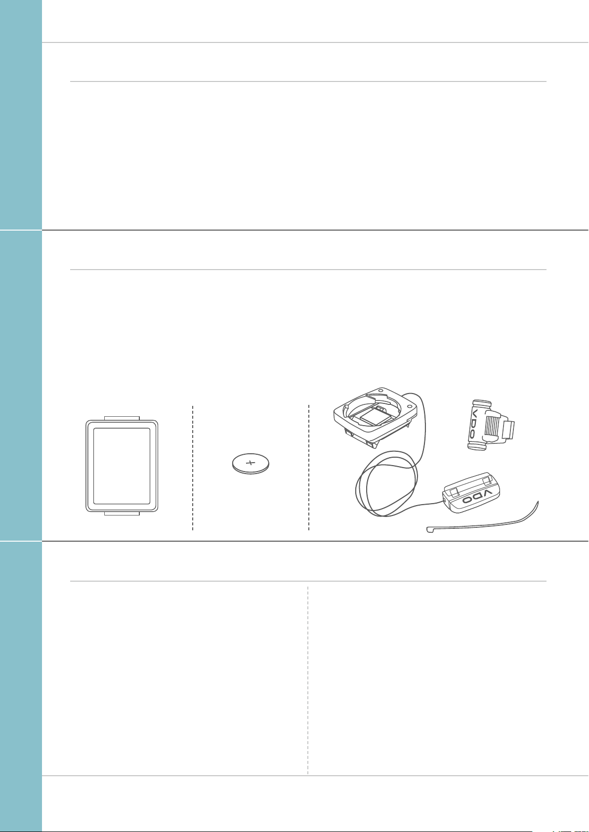
Pack contents
First, please ensure that the contents of this pack are
complete:
M1.1 WR
1 VDO computer
1 battery for the computer
1 universal handlebar bracket with cable and sensor
1 spoke magnet (clip magnet)
Cable ties for attaching the bracket and the sensor
1 quick-start instruction manual
Table of contents
Display ............................................................................ 03
Buttons .......................................................................... 03
Functions ....................................................................... 04
Operation while cycling ............................................... 05
Sleep mode ................................................................... 05
Attaching the handlebar bracket and the sensor ..... 06
Inserting the computer into the bracket ................... 07
Function testing ............................................................ 07
Settings ......................................................................... 08
Language ...................................................................... 08
Wheel circumference .................................................... 09
Unit ............................................................................... 12
Clock ............................................................................. 13
Total distance ................................................................ 16
Resetting trip data after the trip ................................ 17
Battery status indicator .............................................. 18
Replacing the battery in the computer ...................... 18
Terms of guarantee ...................................................... 19
Troubleshooting ............................................................ 20
Technical specifications .............................................. 20
2
Page 3

Display
The VDO M1.1 WR has a large, easy-to-read display that can
be divided into three areas.
M1.1 WR
– The top line of the display permanently indicates
the current speed. If the 12-hour clock format has been
selected, “am” or “pm” appears next to the speed.
It also displays whether kmh or mph has been selected
for the speed indicator.
– The middle line of the display shows the name
of the selected function in clear text.
– The bottom line of the display shows the value
for the selected function.
TOP
MIDDLE
BOTTOM
Buttons
The VDO M1.1 WR has two buttons
BIKE
In function mode:
– Access functions
– Reset trip data to zero
(press and hold)
In setting mode:
– Scroll in the setting menu
– Change the data to be set
SET
In function mode:
– Scroll backwards through the functions
– Open setting mode
(press and hold)
In setting mode:
– Open the setting
– Confirm the setting once ready
– Exit setting mode
and return to function mode
3
Page 4

Functions
The VDO M1.1 WR has the following functions
Current speed
With a wheel circumference of 2,155 mm,
the maximum possible speed is 199 kmh or 124 mph.
Current distance
The current distance counts up to 999.99 km or miles.
If this maximum value is exceeded, the counter restarts the
current distance calculation at zero.
M1.1 WR
Current ride time
The current ride time counts up to 99:59:59 HH:MM:SS.
If this value is exceeded, the ride time counter restarts at
zero.
Current time
(in 24-h or 12-h format)
Total distance
(Cumulative value for all trips)
The total distance counts up to 99,999 km or miles.
If this value is exceeded, the total distance counter restarts at
zero.
24-H format 12-H format
If the unit is switched from miles to km and the conversion
result is greater than 100,000 km, the counter is reset to
zero.
4
Page 5

Operation while cycling
M1.1 WR
While cycling, the display functions can be accessed by
pressing the BIKE button.
Pressing the BIKE button shows the next function on the
display.
By pressing the SET button you can also scroll backwards
through the functions.
Sleep mode
SET
BIKE
1x
If you take a break and the M1.1 WR is in the bracket,
the computer switches to sleep mode after five minutes.
If you set off again after a break, the VDO M1.1 WR has an
auto-start function.
The VDO M1.1 WR instantly switches back to the function
mode and the current speed are once again displayed.
5
Page 6

Attaching the bracket and the sensor
M1.1 WR
Start by attaching the sensor and the magnet.
STEP 1
Place the rubber shim under the sensor. Attach the sensor to
the fork side that corresponds to the side on which you later
want to attach the computer to the handlebars (right or left)
using the cable ties supplied (loosely at first, do not pull tight
just yet).
ATTENTION: the sensor mark on the sensor should point to
the spokes. Depending on the space available, the sensor can
be fitted to the front, inside or back of the fork.
STEP 2
Attach the spoke magnet to an outside spoke. The rod-shaped
magnet core points toward the sensor with the VDO logo.
Align the magnet with the sensor marking on the sensor
at a distance of approx. 1- 5 mm.
STEP 3
Align the sensor and the magnet in their final positions and
fasten them in place: pull the cable ties tight and push the
magnet in firmly.
STEP 4
Move the cable along the fork until it reaches the fork bridge.
From there, wind the cable further along the brake line until it
reaches the handlebars.
1
2
SENSOR
3
1–5 mm
4
STEP 5
Decide whether you want to use handlebar or stem attachment and rotate the base of the handlebar bracket by 90°
accordingly. To do so, undo the screws on the bracket,
remove the foot and rotate it 90° then insert and tighten
the screws again.
ATTENTION: do not overtighten the screws.
STEP 6
Guide the cable ties through the slot in the handlebar bracket,
place around the handlebars or the stem and pull (do not pull
tight just yet).
STEP 7
For handlebar attachment: align the computer angle
to achieve optimum readability.
Now pull the cable ties tight.
Use clippers to snip off protruding cable ends.
A helpful attachment video can be found on our website.
www.vdocyclecomputing.com/service
90°
5 7
–
6
Page 7
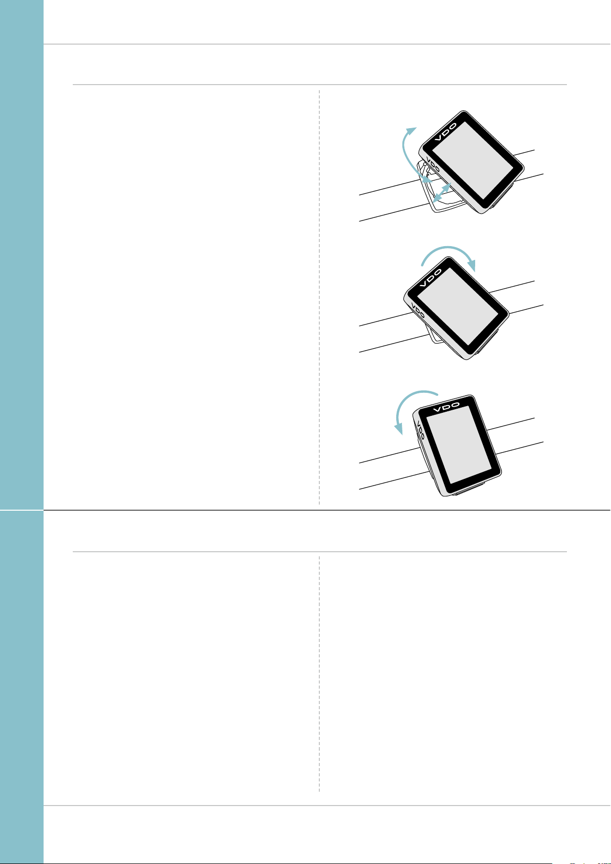
Inserting the computer into the bracket
The VDO twist-click system securely connects the computer
to the handlebar bracket.
M1.1 WR
How to insert the computer:
STEP 1
Place the computer into the bracket in a 10 o’clock position.
STEP 2
Rotate the computer to the right into the 12 o’clock position
and click it into the bracket system. A noticeable resistance
must be overcome to move it into place.
STEP 3
To remove the computer, rotate it to the left (without pushing
or pulling).
Memory aid: Rigid to the Right, Loose to the Left
LOCK
UNLOCK
1. LOCK 2. CLICK
2. UNLOCK
Function testing
Once the sensor has been attached, check that it functions
correctly.
How to test the transmitter:
– Insert the computer into the bracket.
– Lift and spin the front wheel.
– A speed should now be displayed on the computer.
If no speed is displayed, there can be several reasons for this.
The possible reasons are described in the “Trouble-
shooting” section.
7
Page 8

Settings – language
The following display languages can be selected for the
VDO M1.1 WR:
– German
– English
– French
– Italian
– Spanish
– Dutch
– Polish
How to select the language:
Press and hold the SET button until the settings menu
opens.
“Language” appears on the display.
Press SET to open the language setting.
English flashes.
M1.1 WR
You can now press the BIKE button to select a different
language.
Press the SET button to confirm your language setting.
The response “Set Ok” appears on the display.
If you want to configure further settings,
press the BIKE button to access these.
If you do not want to configure any other settings,
press and hold the SET button.
The settings menu closes.
The VDO M1.1 WR returns to function mode.
8
Page 9

Settings – wheel circumference
M1.1 WR
You can set the roll circumference of your wheel on the VDO
M1.1 WR.
The more accurate this setting, the more accurate your speed
indicator and the measurement of the distance you have
travelled.
You can find the values for your wheels in the wheel size table
and set these in the device.
If your wheel size is not listed in the table, you can accurately
measure the roll circumference.
How to measure the roll circumference:
STEP 1
Stand your bike up and position the front wheel so that the
valve is directly on the ground. Ensure that the tyres are fully
pumped up in accordance with the usage instructions. Mark
the position of the valve on the ground with a line or adhesive
strip.
STEP 2
Now push your bike forwards in a straight line until the valve
is back on the ground after one rotation.
Again mark the position of the valve on the ground with a line
or adhesive strip.
KMH
Wheel
circumference
Tyre size ETRTO
16 x 1.75 47-305 1,272 50.1
20 x 1.75 47- 406 1,590 62.6
24 x 1.75 47-507 1,907 75.1
26 x 1.5 40-559 2,026 79.8
26 x 1.75 47-559 2,070 81.5
26 x 1.9 2,089 82.2
26 x 2.00 50-559 2,114 83.2
26 x 2.10 54-559 2,125 83.6
26 x 2.25 57-559 2,145 84.4
26 x 2.35 60-559 2,160 85.0
26 x 2.40 62-559 2,170 85.4
28 x 1.5 40- 622 2,224 87. 6
28 x 1.6 42-622 2,235 88.0
28 x 1.75 47-62 2 2,268 89.3
29 x 2.10 54-622 2,295 90.3
29 x 2.25 57-622 2,288 90.1
29 x 2.40 62-622 2,300 90.5
650 B / 27,5 2180 85,8
700 x 18C 18-622 2,102 82.8
700 x 20C 20-622 2,114 83.2
700 x 23C 23-622 2,095 82.5
700 x 25C 25-622 2,146 84.5
700 x 30C 30-622 2,149 84.6
700 x 32C 32-622 2 ,174 85.6
700 x 38C 38-622 2,224 8 7.6
in mm
MPH
Wheel
circumference
in inches
STEP 3
The distance between the two marks corresponds to your
wheel circumference or wheel size in millimetres.
1x
Wheel circumference in mm/inches
9
Page 10

Settings – wheel circumference
How to set your wheel circumference:
Press and hold the SET button until the settings menu
opens.
“Language” appears on the display.
Press the BIKE button to scroll to the setting for the wheel
circumference.
M1.1 WR
Press the SET button to open the setting for the wheel
circumference.
Setting in mm for KM:
The first two digits flash.
Press the BIKE button to set these digits to the desired
value.
Setting in Inch for Miles:
All digits flash.
Press the BIKE button to set these digits to the desired
value.
Setting in mm for KM:
Press the SET button to confirm your setting.
The third digit now flashes and is ready to be set.
Setting in mm for KM
Setting in mm for KM
Setting in mm for KM
Setting in Inch for Miles
Setting in Inch for Miles
Press the BIKE button to set this digit.
10
Page 11

Settings – wheel circumference
M1.1 WR
Setting in mm for KM:
Press the SET button to confirm your setting.
The final digit on the right now flashes.
Press the BIKE button to set this digit.
Setting in mm for KM/ Inch for miles:
Press the SET button to confirm your setting.
Your wheel circumference setting is now complete.
The response “Set Ok” appears on the display.
If you want to configure further settings,
press the BIKE button to access these.
If you do not want to configure any other settings,
press and hold the SET button.
The settings menu closes.
Setting in mm for KM
The VDO M1.1 WR returns to function mode.
11
Page 12

Settings – unit
Use the unit settings to specify whether the speed should be
displayed in kmh or mph.
Press and hold the SET button until the settings menu
opens.
“Language” appears on the display.
Press the BIKE button to scroll to the setting for the unit.
M1.1 WR
Press the SET button to open the unit setting.
“KMH” flashes in the top line of the display.
Press the BIKE button to change the unit to “MPH”.
Press the SET button to confirm the setting.
The response “Set Ok” appears on the display.
If you want to configure further settings,
press the BIKE button to access these.
If you do not want to configure any other settings,
press and hold the SET button.
The settings menu closes.
The VDO M1.1 WR returns to function mode.
12
Page 13

Settings – clock
In the VDO M1.1 WR, you can set the clock in 12-hour AM/PM
format or 24-hour format.
Press and hold the SET button until the settings menu
opens.
“Language” appears on the display.
Press the BIKE button to scroll to the setting for the clock.
M1.1 WR
Press the SET button to open the setting for the clock.
To switch to the 12-hour AM/PM format,
press the BIKE button.
13
Page 14

Settings – clock
Setting the time in 24-hour format
Press the SET button to confirm the selection “24”.
The hours now flash on the display.
Press the BIKE button to set the hours.
M1.1 WR
Press the SET button to confirm the hour setting.
The minutes then flash.
Press the BIKE button to set the minutes.
Press the SET button to confirm the minute setting.
The response “Set Ok” appears on the display.
If you want to configure further settings,
press the BIKE button to access these.
If you do not want to configure any further settings,
press and hold the SET button.
The settings menu closes.
The VDO M1.1 WR returns to function mode.
14
Page 15

Settings – clock
Setting the time in 12-hour AM/PM format
Press the SET button to confirm the selection “12”.
The hours now flash and “am“ or “pm” appears on the
display.
Press the BIKE button to set the hours.
The display information changes from “pm” to “am”.
M1.1 WR
Press the SET button to confirm the hour/AM-PM setting.
The minutes now flash on the display.
Press the BIKE button to set the minutes.
Press the SET button to confirm the minute setting.
The response “Set Ok” appears on the display.
If you want to configure further settings,
press the BIKE button to access these.
If you do not want to configure any other settings,
press and hold the SET button.
The settings menu closes.
The VDO M1.1 WR returns to function mode.
15
Page 16

Settings – setting the total distance
You can set the total distance ridden on the VDO M1.1 WR. For
example, you can enter your data here at the start of a new
cycling season.
ATTENTION: the M1.1 WR has a data memory.
No data is lost when the battery is replaced.
How to set the total distance:
Press and hold the SET button until the settings menu
opens.
“Language” appears on the display.
Press the BIKE button to scroll to the setting for the total
distance.
M1.1 WR
Press the SET button to open the settings.
The left digit flashes.
Press the BIKE button to change the digit.
Once this digit has been set, confirm the setting
by pressing the SET button.
The next digit starts to flash and is ready to be set.
Press the BIKE button to change this digit.
Once this digit has also been set, confirm the setting
by pressing the SET button.
The next digit flashes.
Once all digits have been set, confirm the setting again by
pressing the SET button.
The response “Set Ok” appears on the display.
The set value is stored.
If you want to configure further settings,
press the BIKE button to access these.
If you do not want to configure any other settings,
press and hold the SET button.
The settings menu closes.
The VDO M1.1 WR returns to function mode.
16
Page 17

Resetting trip data after the trip
After each trip, you can reset the data for this trip to zero.
The VDO M1.1 WR is then ready for the next trip.
ATTENTION: your total distance (total number of kilometres
ridden) is not reset to zero.
The process is as follows:
Press and hold the BIKE button for a few seconds.
The text “RESET Tour Data” appears on the display.
If you continue to hold down the BIKE button,
the trip data is now reset to zero.
The following data is reset to zero:
– Distance
– Ride time
M1.1 WR
17
Page 18

Low battery indicator
The M1.1 WR has a low battery warning.
The text “Computer low” appears on the display.
Press the BIKE button to acknowledge this low battery
warning.
You can keep using the cycle computer for approx. a week.
Replace the battery as soon as possible on seeing the low
battery warning.
Replacing the battery in the computer
To ensure your cycle computer is fully functional,
we recommend replacing the battery annually.
ATTENTION: your settings, total distance and total ride time
information remain stored when you replace the battery.
NO data is lost.
M1.1 WR
You need a 3 V 2032 battery.
We recommend using a branded battery from Sony,
Panasonic, Varta or Duracell.
The process is as follows:
STEP 1
Use a coin to remove the battery compartment cover.
STEP 2
Remove the dead battery.
ATTENTION: Wait for 10 seconds before inserting the new
battery. The electronics need this time to recognise that the
battery is being changed.
STEP 3
Insert the battery into the computer housing
with the +pole up.
Ensure that the battery is not tilted.
Ensure that the rubber seal lies smoothly on the lid of the
battery compartment.
STEP 4
Insert the battery compartment cover into the opening and
use a coin to turn it to right as far as it will go.
OPEN CLOSE
3
NEW
2
10 SEC.
!
1
OLD
18
Page 19

Terms of guarantee
M1.1 WR
VDO Cycle Parts offers a two-year guarantee on your VDO
computer, starting from the date of purchase. This
guarantee covers material and processing defects on the
computer itself, the sensor/transmitter and the handlebar
bracket. Cables, batteries and mounting materials are not
covered by the guarantee.
The guarantee is only valid if the affected components have
not been opened (exception: computer’s battery compartment), no force has been used and there is no sign of wilful
damage.
Please store the purchase receipt in a safe place as it must
be submitted in the event of a complaint.
If your complaint is legitimate, you will receive a comparable
replacement device. You are not entitled to a replacement of
the identical model if the model in question is no longer in
production due to a model change.
Please contact the dealer from whom you purchased the
device for all complaints and guarantee claims. Alternatively,
send your complaint directly to:
Cycle Parts GmbH
Le Quartier Hornbach 13
67433 Neustadt/Weinstrasse
If you have any technical questions, please do not hesitate to
call our hotline on:
+49 (0) 63 21- 95 82 7 - 10
+49 (0) 63 21- 95 82 7 - 18
Our telephone hotline is available to assist you
between the hours of
9:00-12:00, Monday to Friday
service@cycleparts.de
Additional technical information is available at:
www.vdocyclecomputing.com
We reserve the right to make technical changes in the course
of further development.
19
Page 20

M1.1 WR
Troubleshooting
Error Possible cause Correction
Half segments on the display
(e.g. after a battery change)
No speed displayed Distance from sensor to magnet too
No speed displayed Computer not properly clicked
No speed displayed Wheel circumference is set incorrectly
No speed displayed Battery in the transmitter is dead Replace the battery in the transmitter
Display becomes weak Battery dead Check the battery, replace if nec.
Computer software not running
correctly after battery change
great
into the handlebar bracket
or to zero
Remove and re-insert the battery
Correct the sensor and magnet positions
Insert the computer into the handlebar
bracket and rotate it as far as possible
(“click”)
Set the wheel circumference
Technical specifications
Computer:
Approx. 49 H x 38 W x 16 D mm
Display:
H approx. 39 mm, W approx. 29 mm
Computer weight:
Approx. 28 g
Handlebar bracket weight:
Approx. 10 g
Computer battery:
3V, type 2032
Computer battery service life:
Approx. 1 year (approx. 10,000 km/6,000 mi)
Temperature indicator range on the display:
-20°C to +70°C/-4°F to +158°F
Speed range for wheel size 2,155 mm:
Min 2.5 kmh,
Max 199 km/h
Ride time measurement range:
Up to 99:59:59 HH:MM:SS.
Trip distance odometer measurement range:
Up to value 999.99 km or mi
Total km measurement range:
Up to value 99,999 km or mi
Wheel circumference setting range:
From 100 mm to 3999 mm (3.9 to 157.4 inches)
20
Page 21

Correct disposal of this product (electrical waste)
(To be used in EU countries and other European
countries with a separate collection system). The
labelling on the product and the relevant literature
indicates that it must not be disposed of with normal household waste at the end of its service life. Please dispose of
this device separately to other waste so as not to harm the
environment or human health through uncontrolled waste
disposal. Recycle the device to promote the sustainable reuse
of material resources. Private users should contact the retailer
from whom they purchased the product or the responsible
authorities to find out how they can recycle the device in
an environment-friendly manner. Commercial users should
contact their suppliers and consult the conditions of the sales
agreement. This product must not be disposed of with other
commercial waste.
M1.1 WR
EU declaration of conformity
We, CYCLE PARTS GmbH, Le Quartier Hornbach 13,
D-67433 Neustadt/Weinstraße, declare that when used as intended, the VDO cycle computer VDO M1.1 WR complies with
the essential requirements established in the CE Directives.
The declaration of conformity can be found at:
www.vdocyclecomputing.com.
Neustadt, October 2013
21
Page 22

Cycle Parts GmbH
Le Quartier Hornbach 13
67433 Neustadt/Weinstrasse (Germany)
+49 (0) 63 21- 95 82 7 - 0
www.vdocyclecomputing.com
 Loading...