

Page 1

1
Thank you for purchasing a VDO Dayton
subwoofer. Please follow these instructions
carefully so as to fully benefit from the
features that this subwoofer brings to your in
car environment. This manual is produced to
help give you the basic information related to
this system so as to result in a trouble free
installation. In the majority of cases specialist
assistance will be required so as to make the
most from this subwoofer and to ensure that
it delivers a sonic reproduction that is as
accurate as possible therefore we advise that
you seek professional advice.
Important
VDO Dayton subwoofers are designed to suit
a broad range of mobile audio applications
to produce extended, powerful bass in a
limited amount of vehicle space. The installation can require some extensive knowledge
of the car environment. Although these
instructions explain how to install a VDO
Dayton subwoofer in a general sense, they do
not show box-construction details and exact
installation methods for your particular
vehicle. If you do not feel you have the
necessary tools or experience, do not attempt
the installation yourself. Instead ask your
authorised VDO Dayton dealer about
professional installation options to ensure
maximum subwoofer performance.
Remember to keep your sales receipt with
this manual in a safe place so both are
available for future reference.
Think Safety First!
Please ensure that you can hear traffic at all
times and that this installation in no way
hinders the safe operation of the vehicle due
to distraction of the driver.
VDO Dayton accepts no liability for hearing
loss, bodily injury or property damage
resulting from use or misuse of this product.
We want you to fully enjoy this product, so
please use it sensibly.
For more details:
Visit our homepage www.vdodayton.com
General information
on loudspeaker installation
Recommendations
• While preparing the installation of your
subwoofer, please leave it in the box so as
to avoid any damage.
• Please contact your dealer for the correct
mounting solution for your car so that you
allow your subwoofer to perform to the
maximum. For example, there must be
enough room for the cone to extend to its
full excursion.
• Please ensure that the subwoofer does not
hinder the safe operation of the vehicle.
• Due to the weight and size of this
subwoofer, it will work at its best if the
correct mounting solution is custom made
for your vehicle. To get the most detail and
power from your loudspeaker, make sure
that it has a solid mounting free from
vibration. We recommend the use of an
enclosure.
• To further improve the installation, we
recommend the use of damping material.
Please consult your dealer for details.
• Finally, ensure that the installation is
completely airtight.
Adjusting subwoofer level
The subwoofer level can be adjusted to suit
the environment, placement and personal
preference. You should not be able to hear
the subwoofer as a separate source. Its sound
should be an integrated part of your total
system.
Let your personal preference be the deciding
factor!
English
Page 2

2
Subwoofer phase
In most cars the standard in-phase connection
(+ speaker to + amp) of the subwoofer will be
the right one. In some cases, it sounds better
if you connect it out of phase. Just change
the polarity: Connect the + terminal of the
subwoofer to the – terminal of the amp
and the – terminal of the subwoofer to the
+ terminal of the amp.
Wiring
Quality and size of wire has a strong effect on
the quality of sound. VDO Dayton therefore
recommends a minimum specification of
2.5 sq. mm oxygen-free copper (OFC) wire,
but ask your dealer for your specific
installation.
Power recommendation
The power handling of VDO Dayton subwoofers is very high. Therefore, choose an
amplifier that is powerful enough to drive
the speaker well. An amplifier that is too
small will distort quickly. This will limit level
and quality of sound and possibly cause
damage to the loudspeakers.
A few words about enclosures
Your VDO Dayton subwoofer requires a
sealed enclosure to realise its full low-frequency response.
Be aware that infinite-baffle or "free-air"
mounting will reduce the power handling of
any subwoofer compared to an application
using an enclosure. Finally, any deviation
from recommended enclosures should be
made using dedicated enclosure design
software. If this type of software is not
available to you, ask your authorised VDO
Dayton dealer for help.
VDO Dayton accepts no liability for damage
to the product due to deviation from the
recommended box designs.
YOUR CAR AND BASS REPRODUCTION
Depending on the size of the vehicle’s interior
listening space, reproduced bass frequencies
below 80Hz are boosted by nearly 12dB per
octave in the car as frequency decreases.
NOTE: This effect, known as the vehicle’s
transfer function, plays an important part in
shaping the over-all in-car response along
with freespace response on the enclosed data
sheet for your VDO Dayton subwoofer.
ENCLOSURE CALCULATIONS
AND BUILDING BOXES
Use the recommended box design on the
enclosed data sheet. Choose cabinet
dimensions to fit your vehicle, but do not
change the enclosure’s volume. Doing so will
change the tuning frequency of the enclosure
and may adversely affect final performance. If
you cannot perform the necessary
calculations yourself, please contact your
authorised VDO Dayton dealer for help. In
addition, there are a number of points you’ll
want to keep in mind as you construct an
enclosure:
1. Use 19 mm MDF (medium-density fiberboard) or marine birch wood to build an
enclosure. Enclosures for 30 cm and larger
subwoofers, or small subwoofers driven by
high-power amplifiers should be
constructed using 26 mm material.
2. Seal all joints with glue and screws; do not
use nails. We recommend "deck", "zip" or
drywall screws since they have coarse
threads for better grip and don’t require
pre-drilling holes. Once the box has been
tested, seal all interior joints with silicone
caulk.
Page 3

3
POWER HANDLING LIMITATIONS
The power handling capability of any woofer
is related to both its ability to dissipate heat
and the maximum excursion limits of its cone.
Once the voice coil moves completely outside
the magnetic gap, power can no longer be
converted into motion and all the amplifier’s
power is converted into heat in the voice coil.
Voice coil heating is the largest detriment to
speaker longevity, so overexcursion should be
avoided. Since cone excursion is different for
each type of enclosure, power handling is
different for each enclosure.
Sealed enclosures exert the most control over
the motion of a subwoofer, because the air
inside the box acts like a spring against the
motion of the woofer cone. Larger boxes
allow for more excursion, thus providing
more low-frequency output for the amount
of power used. When placed in a sealed box
larger than the Vas of the subwoofer, it will
perform as if it were in an infinite-baffle
installation.
• Voice coil overheating and burning due to
over excursion are often caused by
overdriving an amplifier into "clipping".
A severely clipped signal, or square wave,
contains nearly twice the power of a clean
sine wave at the same level. Bass that
sounds broken up and distorted at higher
volumes is usually indicative of an amplifier
that is clipping and being asked to deliver
power beyond its rated power.
• Infinite-baffle or "free-air" mounting
applications allow for greater cone
excursion than subwoofers mounted in an
enclosure. In order to compensate,
recognise that the power rating value of
the subwoofer will likely be half its rated
power in this application. Therefore we do
not recommend these applications.
• As long as recommended parameters are
used, the subwoofer will perform properly
in its enclosed environment. However, any
design deviation may result in less than
optimum performance, and may also
subject the subwoofer to over-excursion
(i.e., the voice coil leaves the gap) that can
damage the speaker. For additional advice,
please contact your authorised VDO Dayton
dealer.
VDO Dayton accepts no liability for damage
to the product due to deviation from the
recommended box designs.
English
Page 4

4
Your VDO Guarantee
Dear customer, Thank you for purchasing
this VDO Dayton product which has been
designed and manufactured to the highest
standards and subjected to rigorous
testing. Provided it is properly operated
and maintained it will perform well for
many years.
VDO Dayton guarantees to provide free of
charge labour and replacement parts in
any country where VDO Dayton has
authorised dealers for all serviceable VDO
Dayton branded consumer electronic
products purchased in those countries.
The legal responsibility for meeting any
guarantee service needs for your product
rests with the dealer from whom you
bought it. If your dealer has no service
facilities, he can arrange for any work to
be carried out by a competent authorized
third-party organisation.
In the event that you require service whilst
in another country please contact the local
VDO Dayton Help Desk whose number can
be found in the relevant part of this
booklet.
The foregoing applies during a period of
24 months from the date of purchase,
provided the product is properly used in
accordance with its operating instructions
and upon presentation of the original
invoice or cash receipt indicating the date
of purchase, dealer’s name with the
product type and serial number.
The VDO Dayton guarantee may not
apply if:
• The invoice or cash receipt has been
altered in any way or made illegible.
• The type or serial number on the product
has been altered, deleted, removed or
made illegible.
• Repairs have been executed by unauthorised service organisations or persons.
• Damage is caused by accidents including
and not limited to lightning, water or
fire, misuse or neglect.
• The product requires modification or
adaption to operate in any country other
than the country for which it was
designed and manufactured, or if any
damage results from these modifications.
In order to avoid unnecessary
inconvenience, we advise you to read the
operating instructions carefully before
contacting your dealer or service
organisation.
Continuing service after the guarantee
period is available but the service will be
chargeable.
Page 5
5
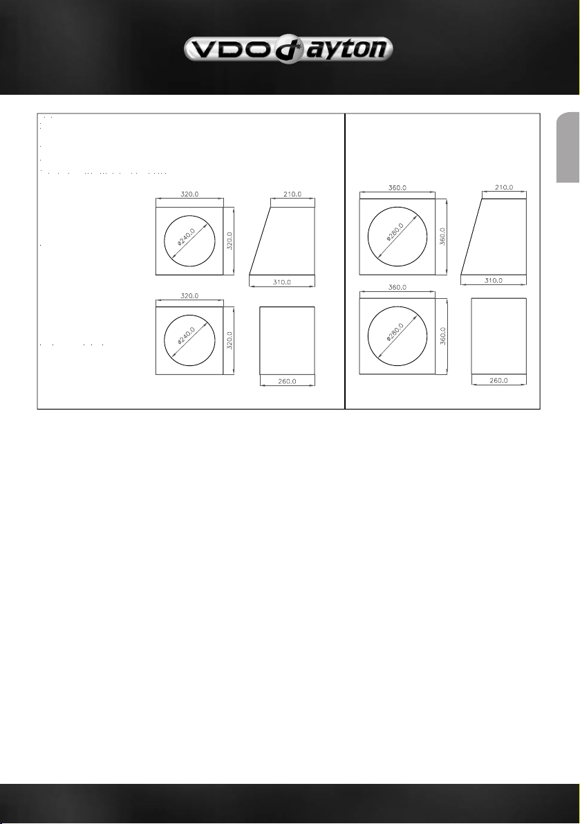
VDO HPS 10
English
Volume:
HPS 10 = 14 liters net.
HPS 12 = 18 liters net.
(with 19 mm panel thickness)
Dimensions:
All dimensions in mm.
(Divide by 10 to get cm)
Unit Mounting Hole: 240mm Unit Mounting Hole: 280mm
VDO HPS 12
ANGLE
REGULAR
Front
Side
Front
Side
Page 6

6
HPS 10", sealed box, 14 liters in car measurement Custom Amplitude Response (dB SPL/Hz at 1 m) with 300 Watts
BassBox 6 Pro
HPS 12", sealed box, 18 liters in car measurement Custom Amplitude Response (dB SPL/Hz at 1 m) with 300 Watts
BassBox 6 Pro
Page 7

7
Thiele Small Parameters HPS 10 HPS12
Min. Impedance/ at Freq Zmin(Ohm/ Hz) 4.0/154 4.0/133
Maximum Impedance Zo Ohm 25.7 24.0
DC Resistance Re Ohm 3.3 3.3
Voice Coil Inductance Le (mH) 1.6 1.8
Capacitor in series with 4 Ohm Cc (µF) 80 75
Resonance Frequency fs (Hz) 46.0 38.8
Mechanical Q Factor Qms 4.44 3.93
Electrical Q Factor Qes 0.64 0.62
Total Q Factor Qts 0.56 0.54
F (ratio fs/Qts) F (Hz) 82 72
Mechanical Resistance Rms (Kg/s) 7.38 8.09
Moving Mass Mms (g) 113.2 130.1
Suspension Compliance Cms (mm/N) 0.113 0.132
Effective Cone Diameter D (cm) 21.2 24.4
Effective Piston Area Sd (cm2) 352 466
Equivalent Volume Vas (ltrs) 18.1 38.8
Force Factor Bl (N/A) 12.9 12.9
Linear Xmax Peak Xmax (mm) 12.5 12.5
Max Mechanical Xmax Peak Xmax (mm) 22 22
Voice Coil Diameter d (mm) 51 51
Voice Coil Length h (mm) 33 33
Voice Coil Layers n 4 4
Flux Density in Gap B (T) 1.04 1.04
Total Useful Flux (mWb) 2.5 2.5
Height of the Gap (mm) 8 8
Diameter of Magnet (mm) 147 147
Height of Magnet (mm) 35 35
Weight of Magnet (kg) 2.42 2.42
Speakers
Model HPS10 HPS12
Description Subwoofer Subwoofer
Specification
Max. Power Watts 800 1000
Nominal Power Watts 300 400
Sensitivity dB/1W/m 92 93,5
Nominal Impedance (Ohm) 4 4
Frequency Response 24-400Hz 21-400Hz
Materials
Cone Nomex/Kevlar/ Nomex/Kevlar/
Glassfibre Composite Glassfibre Composite
Basket Material Cast Aluminium Cast Aluminium
Woofer Magnet Strontium Ferrite Strontium Ferrite
Voice Coil info Aluminium Aluminium
Connectors Gold-plated Gold-plated
Dimensions and Weight
Woofer Size 250 mm 300 mm
Mounting Diameter Woofer 239 mm 277 mm
Mounting Depth 122 mm 130 mm
English
Page 8

quency
M
Fre
: 830500
echanical Dimensions:830500
Tymphany™ and are trademarks of Tymphany Corporation. © 2009, Tymphany Corporation. All rights reserved. 012409
 Loading...