

Page 1
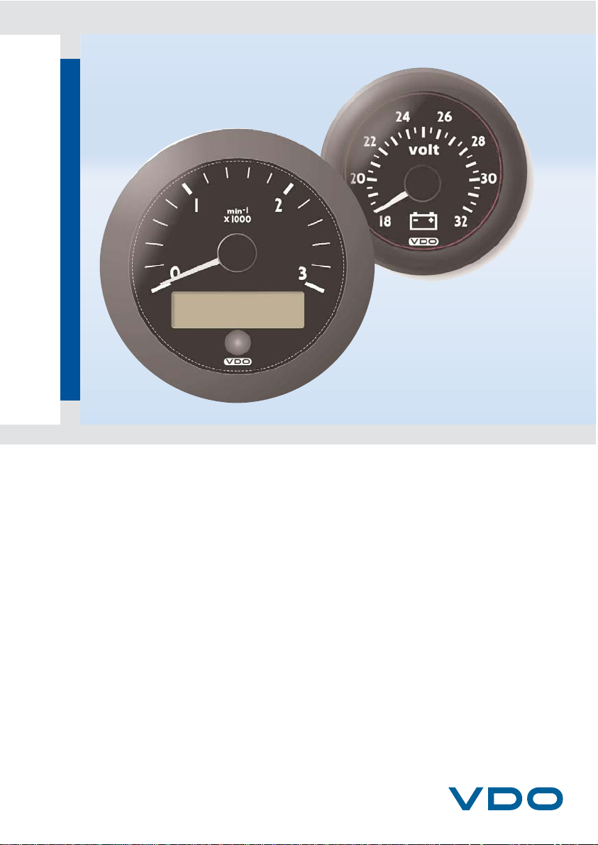
Tachometer
CAN Central Instrument
Easy Link
Satellite Gauge
Installation and Operating Instructions
Page 2

2
Contents
Safety instructions . . . . . . . . . . . . . . . . . . . . . . . . . . . . . . 3
On the installation manual . . . . . . . . . . . . . . . . . . . . . . . . . . . . . . . . . . . . 3
On the notes used . . . . . . . . . . . . . . . . . . . . . . . . . . . . . . . . . . . . . . . . . . . . 3
On power supply . . . . . . . . . . . . . . . . . . . . . . . . . . . . . . . . . . . . . . . . . . . . . 4
On installation . . . . . . . . . . . . . . . . . . . . . . . . . . . . . . . . . . . . . . . . . . . . . . . 5
If the device is defective . . . . . . . . . . . . . . . . . . . . . . . . . . . . . . . . . . . . . . . 6
Maintenance and cleaning . . . . . . . . . . . . . . . . . . . . . . . . . . . . . . . . . . . . . 6
Storage and transportation . . . . . . . . . . . . . . . . . . . . . . . . . . . . . . . . . . . . . 6
Disposal. . . . . . . . . . . . . . . . . . . . . . . . . . . . . . . . . . . . . . . . . . . . . . . . . . . . 6
1. Ocean Link Tachometer . . . . . . . . . . . . . . . . . . . . . . . 7
2. Components . . . . . . . . . . . . . . . . . . . . . . . . . . . . . . . . . 8
2.1 Accessories . . . . . . . . . . . . . . . . . . . . . . . . . . . . . . . . . . . . . . . . . . . . . . . 8
3. Functions of the Tachometer . . . . . . . . . . . . . . . . . . . 9
4. Displays and Setting Possibilites . . . . . . . . . . . . . . . 10
4.1 Basic Settings . . . . . . . . . . . . . . . . . . . . . . . . . . . . . . . . . . . . . . . . . . . . . 10
4.1.1 Selection of the display units . . . . . . . . . . . . . . . . . . . . . . . . . . . . . 10
4.1.2 Selection of the baud rate . . . . . . . . . . . . . . . . . . . . . . . . . . . . . . . 10
4.1.3 Setting the inputs . . . . . . . . . . . . . . . . . . . . . . . . . . . . . . . . . . . . . 11
4.1.4 Selection of fuel tank signal . . . . . . . . . . . . . . . . . . . . . . . . . . . . . . 11
4.1.5 Selection of the function of the 4-20 mA sensor . . . . . . . . . . . . . . 12
4.1.6 Setting number of exhaust gas temperature measured values . . . 12
4.1.7 Setting the illumination . . . . . . . . . . . . . . . . . . . . . . . . . . . . . . . . . 12
4.1.8 Selection of the displays . . . . . . . . . . . . . . . . . . . . . . . . . . . . . . . . 13
4.1.9 Activation of the simulation mode . . . . . . . . . . . . . . . . . . . . . . . . . 13
4.1.10 Ending the settings . . . . . . . . . . . . . . . . . . . . . . . . . . . . . . . . . . . . 13
5. Main Functions . . . . . . . . . . . . . . . . . . . . . . . . . . . . . . 14
6. The CAN Interface. . . . . . . . . . . . . . . . . . . . . . . . . . . . 15
7. Installation of the Tachometer. . . . . . . . . . . . . . . . . . 17
8. Installation of the Satellite Gauge. . . . . . . . . . . . . . . 19
9. Electrical Installation (pin assignment) . . . . . . . . . . 21
10.Cable Lengths . . . . . . . . . . . . . . . . . . . . . . . . . . . . . . 21
11.Technical Data. . . . . . . . . . . . . . . . . . . . . . . . . . . . . . . 22
Page 3
3
Safety instructions
This product was developed, manufactured and tested in accordance with the basic
safety requirements of EU Directives and the latest technological standards.
Changing or tampering with a VDO product can affect safety. Therefore, the product may not be changed or tampered with.
On the installation manual
• This manual is subject to German copyright law. It may not be duplicated, edited, distributed or used in any way that violates copyright laws without the explicit consent of the manufacturer. This manual may only be copied for private,
non-commercial use.
• Read this manual thoroughly before starting the installation. Keep the manual in
a safe place. If you pass the device on to third parties, include the manual.
• Failure to follow the instructions in this manual can result in injury or damage to
the device or vehicle.
• We are not liable for damage resulting from failure to follow the instructions in
this manual.
On the notes used
• Important notes are labeled accordingly. Always read these notes to avoid accidents and damage to the device:
On specific target groups
• To avoid damage to property or the environment, installers must have a basic
knowledge of electrical and mechanical systems for the automotive/shipbuilding
industry.
WARNING:
Warns you about hazards to your health and indicates possible risk of injury.
NOTE:
Highlights tips and information for you.
i
Page 4

4
On intended use
• This device is intended for use in vehicles and machines on land as well as in
recreational ships (including non-classified commercial ships). Any other use is
considered improper use and is prohibited. Improper use of the product can result in personal injury or damage to property or the environment.
The following is prohibited:
• Do not operate the device in the vicinity of explosive or flammable materials.
This could cause a fire or explosion.
On power supply
• Ensure the proper cable cross section. For sensor lines, use cables at least 0.5
mm², for power supply lines see detailed information in the installation instruction.
• Smaller cable cross section can result in higher current density. This can cause
the relevant section of cable to heat up.
• When laying electrical cables, use existing cable ducts and wiring harnesses.
However, do not run cables parallel to ignition cables or cables that lead to large consumers of power.
• Secure the cables with cable ties or adhesive tape. Do not run cables over moving parts. Do not attach cables to the steering column.
• Ensure that cables are not subjected to tensile forces, compressive forces or
shearing forces.
• When running cables through holes, use rubber sleeves or similar protectors to
prevent damage to cables.
• Only use wire strippers to remove insulation from cables. Set up the stripper so
that stranded wires are not damaged or cut off.
• New cable connections must be soft-soldered, or standard crimping terminals
must be used.
• Only use crimpers to connect crimping terminals. Observe the safety instructions of the crimper manufacturer.
• Insulate stranded wires to eliminate the risk of short circuits.
• Caution: Faulty connections or damaged cables can result in short circuits.
• Short circuits in the on-board power supply can cause cable fires, battery explosions and damage to other electronic systems. Therefore, insulate all connections in the power supply using weldable butt connectors and ensure adequate
insulation.
• Take special care to ensure correct ground connections.
• Incorrect connections can result in short circuits. Always connect cables in accordance with the electrical circuit diagram.
• When operating the device with power units, make sure that the power unit is
stabilized and meets the following standards: DIN EN 61000- Section 6-1 to 6-4.
Page 5

5
On installation
• The product should be installed by an expert who specializes in the installation
of the product. If you install the product yourself, wear appropriate work clothes.
Do not wear loose clothing that can become caught in moving parts. If you have
long hair, wear a hair net.
• Before installation, read the vehicle documentation to learn about the type of vehicle and any special features that may be relevant.
• Look at blueprints to find out where the fuel lines, hydraulic lines, compressed
air and electrical lines are located. Make note of any modifications to the vehicle
that you might need to consider during installation.
• Ensure that the engine cannot accidentally start during installation.
• When removing or installing seats, covers, etc., make sure not to damage any
lines or disconnect any plugs.
• Make a note of all data stored in other installed devices with volatile electronic
memories.
Pay attention to the following during installation:
• During installation, ensure that the components of the product do not affect or
impair vehicle functions and do not become damaged themselves.
• Install only undamaged parts in a vehicle.
• During installation, ensure that the product does not impair visibility and is not
positioned in the head impact zone of the driver or passenger.
• When working on on-board electronics, do not wear metallic or conductive jewelry such as necklaces, bracelets, rings, etc.
• If you have to work on a running engine, take special precautions. Always wear
appropriate work clothes due to risk of injury from crushing and burns.
• Before starting work, disconnect the negative terminal of the battery to avoid
short circuits. If the vehicle has additional batteries, the negative terminals of
these batteries may also need to be disconnected.
• Short circuits can cause cable fires, battery explosions and damage to other electronic systems. Remember that when you disconnect the battery, all volatile
electronic memories will lose their entries and must be reprogrammed.
• Before working on the engine compartment of a gas-powered ship engine, run
the engine compartment fan for at least five minutes.
• Note the paths of lines and wiring harnesses to avoid damaging them when drilling or sawing.
• Do not install the product near the mechanical and electrical systems for the airbag.
• Do not drill holes or make openings in stabilizing struts or side bars.
• Before working under the vehicle, secure it in accordance with the manufacturer's instructions.
• When choosing an installation location, make sure there is enough space behind the holes or opening.
Page 6

6
• Drill small openings first, then enlarge them with a cone cutter, hole saw, jigsaw
or file, if necessary. Deburr sharp edges. Always observe the safety instructions
of the tool manufacturer.
• If it is necessary to work without interrupting the power supply, always use an
insulated tool.
• To measure voltage and current in the vehicle, machine or ship, always use
multimeters or diode test lamps specially designed for this purpose. Using conventional test lamps can damage control units or other electronic systems.
• Ensure that the electrical outputs of the display unit and the cables connected
to it are protected against direct contact and damage. This means that the cables used must have sufficient insulation or voltage stability and the contact
points must be protected against contact.
• Also take appropriate measures to ensure that the electrically conductive parts
of the connected loads are protected against direct contact. Use of bare metal
cable and contacts is not permitted.
After installation
• Connect the grounding cable to the negative terminal of the battery.
• If necessary, enter data in the volatile electronic memory.
• Check all the functions of the newly installed device.
If the device is defective
• Never operate a defective device.
• Give defective devices to your VDO dealer for testing.
Maintenance and cleaning
• The device does not contain any parts or components that require maintenance.
• Use only pure water for cleaning components. Observe the IP codes when cleaning (IEC 60529).
Storage and transportation
• Do not subject the device to temperatures defined in the corresponding data
sheet of the product.
Disposal
• Do not dispose of the device as household waste.
Take the device to a recycling center for electrical and
electrotechnical equipment.
Page 7
7
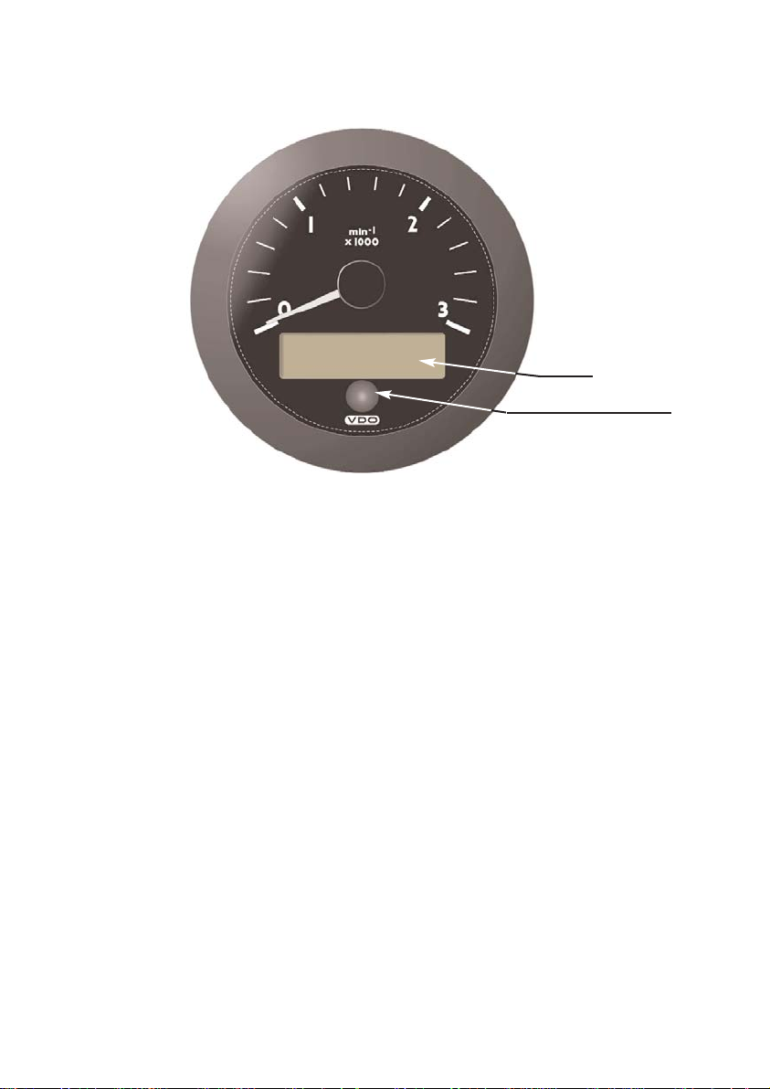
1. Ocean Link Tachometer Basic Information
The VDO Ocean Link tachometer is a multifunctional instrument for indicating engine data, and is intended for use in navigation of sports ships. The tachometer
shows the actual engine speed in operation, on the analogue scale. Further values
and operating aids appear in the LCD.
The instrument has a push-button menu key on the front side, with which all the
functions can be selected. Handling of the instrument is thus easy and uncomplicated. The instrument is connected to the engine electronics through a CAN bus, and
receives the engine data. In addition, the display unit is provided with a bus output
for transmitting data to Easy Link Satellite gauges. A maximum of Easy Link
Satellite gauges can be connected.
The instrument is also provided with 2 sensor inputs for analogue VDO sensors.
LCD
Push-button menu key
Page 8

8
2. Components
The supply schedule includes the following:
• display unit
• a set of parts for fixing the display unit
• assembly and operating instructions
2.1 Accessories
(not included in the supply schedule):
• Ocean Link front bezels in various colours
• Easy Link satellite gauges
Page 9

9
3. Functions of the Tachometer
Displays:
• Engine speed (indicated by means of a pointer)
• Engine hours (indicated in LCD)
• Engine oil pressure (indicated in LCD)
• Transmission oil pressure (indicated in LCD)
• Transmission oil temperature (indicated in LCD)
• Cooling water temperature (indicated in LCD)
• Engine oil temperature (indicated in LCD)
• Battery voltage (indicated in LCD)
• Instantaneous fuel consumption (indicated in LCD)
• % load (indicated in LCD)
• Intake air temperature (indicated in LCD)
• Charge air temperature (indicated in LCD)
• Exhaust gas temperature (indicated in LCD)
• Fuel level (indicated in LCD)
• Water level (indicated in LCD)
• Exhaust gas temperature before turbine (indicated in LCD)
• Vehicle speed (Easy Link satellite gauge)
Setting possibilities:
• Selection of illumination intensity in 8 steps
• Selection of display unit in metric or English units
• Selection of CAN baud rate
• Selection of sensor types for the analogue inputs
• Selection of the number of charge air pressure inputs
• Illumination - internal / external
• Selection of display modes
• Activation of the simulation mode
Page 10

4. Displays and Setting Possibilites
4.1 Basic Settings
The basic settings necessary for perfect operation can be selected in the settings
menu. These are obtained by pressing and holding the push-button key while
switching on the power supply of the display.
Display units: Selection of display unit (see p. 8)
Baud rate: Selection of baud rate (see p. 8)
Config inputs: Setting the inputs (see p. 9)
Screens on / off: Selection of displays (see p. 11)
Simulator mode: Activation of simulation mode (see p. 11)
Exit setup: Ending the setting menu (see p. 11)
In order to change a value (e.g. from No to Yes), press the push-button key briefly.
In order not to change a value, keep the push-button key pressed until the set value flashes once. Then release the push-button key immediately. Through this the
displayed setting is taken over. If the push-button key is not pressed, the displayed
setting is automatically taken over after 10 seconds.
4.1.1 Selection of the display units
The values for temperatures and pressures can be displayed alternatively in the
units °C/bar (METRIC) or °F/psi (ENGLISH). Selection of the units is carried out as
follows:
Example:
In the example shown the unit is changed from METRIC to ENGLISH.
4.1.2 Selection of the baud rate
The rate at which values are transmitted on the CAN bus can be set to 250 kB/s
(250 kBps) or alternatively to 500 kB/s (500 kBps). Selection of the baud rate is
carried out as follows:
BAUDRATE
250kBps
Press key
BAUDRATE
500kBps
10
DISPLAY UNITS
METRIC
Press key
DISPLAY UNITS
ENGLISH
Page 11

4.1.3 Setting the inputs
(config inputs)
In this menu the following settings are possible:
Fuel tank signal: Selection of fuel quantity signal (see p. 9)
4-20 mA input: Selection of function of 4-20 mA transmitter (see p. 10)
Change boost amount: Setting number of exhaust gas temperature
measured values (see p. 10)
External illumination: Setting of illumination (see p. 10)
4.1.4 Selection of fuel tank signal
Select here from which signal source the fuel tank signal is transmitted:
Off: No display of fuel quantity
CAN: Fuel tank signal from CAN bus
Lever: Fuel tank signal from lever type sensor
Pipe: Fuel tank signal from dip type sensor
When using a dip type sensor, calibration must be carried out. This is always carried out with the tank empty. For this the procedure is as follows:
Example:
Ensure that the tank is empty
DO TANK KALIBRATION ?
YES
TANK IS NOT CALIBRATED
ATTENTION
TANK MUST BE EMPTY
11
Keep key pressed
Keep key pressed
Press key
FUEL TANK S I GNAL
PIPE
DO TANK KALIBRATION ?
NO
TANK IS NOT CALIBRATED
Page 12

MEASURED RES: VAL: 85
YES
SAVE VALUE FOR CAL. ?
12
4.1.5 Selection of the function of the 4-20 mA sensor
Select here which function the 4-20 mA water level sensor has.
Off: No display of water level
FRESH WATER: Display of fresh water level
WASTE TANK: Display of waste water tank level
4.1.6 Setting number of exhaust gas temperature measured values
(change boost amount)
Select here whether one or two measured values are to be displayed for the exhaust gas temperature before the turbine.
1: One exhaust gas temperature measured value
2: Two exhaust gas temperature measured values
(V-type engines)
4.1.7 Setting the illumination
(external illumination)
Select here whether illumination of the tachometer and the connected satellite
gauges are to be connected internally or externally.
EXTERNAL: The illumination is switched on and off through an input of the 14-
pole plug. Dimming of the illumination is thus not possible.
INTERNAL: The illumination is regulated in the normal operating mode by
pressing and holding the push-button key in 8 steps.
Keep key pressed
MEASURED RES: VAL: 85
NO
SAVE VALUE FOR CAL. ?
TANK
CALIBRATED
Page 13

13
4.1.8 Selection of the displays
(screens on / off)
Select here which measured values are to be displayed in the normal operating
mode.
YES: Here all measured values, with their ISO symbol, are displayed.
By selecting NO the measured value can be removed from the
normal operating mode.
If the measured value is to be displayed again, select YES when
the ISO symbol of the measured value is displayed.
NO: No changes in the setting are made.
4.1.9 Activation of the simulation mode
(simulator mode)
Select here whether the simulation mode is to be switched on.
YES: The simulation mode is switched on. The display now generates
random values for all measuring channels and displays these. The
measured values are also transmitted to the bus instruments.
NO: The simulation mode is switched off.
Please note that the simulation mode still remains active after switching off and
switching on again, if it has not been switched off by selecting NO.
4.1.10 Ending the settings
(exit setup)
Select here whether the settings are to be exited.
YES: The settings are exited, the display restarts in the
normal operating mode.
NO: The settings are restarted.
Page 14

5. Main Functions
The main functions of the VDO Ocean Link tachometer can be called by pressing
the push-button key. Each time the key is pressed, the next measured value is displayed.
14
Engine hours Engine oil pressure Transmission oil pressure
Transmission oil
temperature
Cooling water
temperature
Engine oil
temperature
Instantaneous fuel
consumption
% loadBattery voltage
Intake air temperature
Charge air pressure Exhaust gas temperature
Fuel level
(depending on the setting)
Water level
(depending on the setting)
Exhaust gas temperature before
turbine 1 (depending on the setting)
Exhaust gas temperature before
turbine 2 (depending on the setting)
Page 15

15
If you keep the push-button key pressed for 4 seconds, the roll bar for the illumination setting appears. By repeated pressing of the key you can change the illumination of the tachometer and the connected satellite gauges in 8 steps. The display
jumps back to the normal operating mode 8 seconds after the last key press. The
illumination setting is retained even after switching off the power supply and switching on again.
Please note that setting of the illumination is possible only if external illumination is
set to INTERNAL in the settings menu.
6. The CAN Interface
The VDO Ocean Link tachometer receives data from a CAN 2.0 B interface. Data
in the SAE J1939 format are transmitted on this interface. The parameter group
numbers (PGN) of the data which the display receives are given in the table below.
More detailed information is given in the respective sections of the SAE J1939
standard. This standard can be found under http://www.sae.org
List of measured values SAE J1939/71 Oct. 1998
Measured value: Section no.: PGN:
% load 5.2.1.7 61443
Exhaust gas temperature 1 (before turbine) 5.2.5.207 65176
Exhaust gas temperature 2 (before turbine) 5.2.5.207 65176
Exhaust gas temperature 5.2.5.8 65270
Intake air temperature 5.2.5.4 65270
Engine hours 5.2.5.61 65253
Engine speed 5.2.1.9 61444
Vehicle speed 5.2.1.12 65265
Fuel consumption (ltr/hr) 5.2.5.63 65266
Fuel level 5.2.5.71 65276
Cooling water temperature – engine 5.2.5.5 65262
Charge air pressure 5.2.5.36 65270
Oil pressure – transmission 5.2.5.24 65272
Oil pressure – engine 5.2.5.28 65263
Oil temperature – transmission 5.2.5.17 65272
Oil temperature – engine 5.2.5.15 65262
Battery voltage 5.2.5.75 65271
Page 16

16
List of parameter groups used SAE J1939/71 Oct. 1998
Designation: Section no. PGN:
ELECTRONIC ENGINE CONTROLLER #2 5.3.6 61443
ELECTRONIC ENGINE CONTROLLER #1 5.3.7 61444
ENGINE HOURS; REVOLUTIONS 5.3.19 65253
ENGINE TEMPERATURE 5.3.28 65262
ENGINE FLUID LEVEL/PRESSURE 5.3.29 65263
CRUISE CONTROL/VEHICLE SPEED 5.3.31 65265
FUEL ECONOMY 5.3.32 65266
INLET/EXHAUST CONDITIONS 5.3.36 65270
VEHICLE ELECTRICAL POWER 5.3.37 65271
TRANSMISSION FLUIDS 5.3.38 65272
DASH DISPLAY 5.3.42 65276
TURBOCHARGER INFORMATION #4 5.3.97 65176
Display of battery voltage:
Voltage Term.15
available?
Display
voltage Term.15
Display voltage
measured by the indicator
Voltage Term. 30
available?
Display
voltage Term.30
YES
YES
NO
NO
Page 17

17
7. Installation of the Tachometer
73 mm
dia. 86 mm
dia. 105 mm
0.3m
Before beginning, disconnect the negative terminal on the battery, otherwise you risk a short circuit.. If the vehicle is supplied by auxiliary batteries, you must also disconnect the negative on
these batteries! Short circuits can cause fires, battery explosions and damages to other electronic
systems. Please note that when you disconnect the battery, all volatile electronic memories lose
their input values and must be reprogrammed.
Page 18

18
A 0.5 ..6.5 mm
B 6.5...16.5 mm
A
B
or
Please note that when you disconnect the battery, all volatile electronic memories lose their
input values and must be reprogrammed.
Page 19

8. Installation of the Satellite Gauge
A: 0,5...5 mm
B: 5... 15 mm
A
B
or
19
36 mm
0,5 ... 15 mm
Ø 53mm
0,3m
dia. 63 mm
dia. 52 mm
Before beginning, disconnect the negative terminal on the battery, otherwise you risk a short circuit.. If the vehicle is supplied by auxiliary batteries, you must also disconnect the negative on
these batteries! Short circuits can cause fires, battery explosions and damages to other electronic
systems. Please note that when you disconnect the battery, all volatile electronic memories lose
their input values and must be reprogrammed.
Page 20

20
Fasten Retainer Nut
Hand Tight Only
Tachometer
CAN Master
Easy Link
Gauge 1
Easy Link
Gauge 2
Easy Link
Gauge 3
......max. 20 Gauges
max. 20 m Cable Length
Please note that when you disconnect the battery, all volatile electronic memories lose their
input values and must be reprogrammed.
Page 21
21
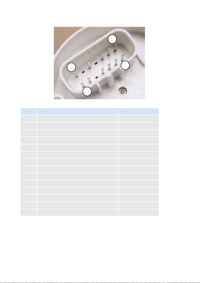
G
H
P
A
9. Electrical Installation (pin assignment)
10. Cable Lengths
Permissible cable lengths for the Easy Link satellite bus are 20 metres. The total
number of Easy Link satellite gauges displays which are connected to the Easy
Link bus must not exceed 20.
Pin: Assignment: Color
A Satellite Bus Power red/white
B Analogue input 4-20 mA blue/white
C Analogue input 0-200 Ohm grey/white
D Satellite Bus Ground / Signal Ground black/grey
E not connected purple
F Term. 31 (GND) black
G Term. 30 (Battery power) red
H Satellite Bus yellow
J CAN high green
K CAN low blue
L not connected brown
M Term. 58 (illumination) grey
N not connected pink
P Term. 15 (ignition) Data orange/brown
Page 22

22
11. Technical Data
Power supply: 10 to 30 VDC
Current consumption: approx. 120 mA without illumination
approx. 140 mA with illumination
Illumination: red, dimmable, amber display
Operating temperature: - 20 to + 70°C
Type of protection: DIN 40050 –IP 65 front side
EMV: CE according to EMV 83/336/EEC
Data input: CAN 2.0 B; SAE J1939
analogue 4-20 mA
analogue 0-200 Ohm
Data output: VDO Easy Link satellite bus
Dimensions: 85 mm built-in diameter
73 mm built-in depth (including cable)
Connection: Delphi plug, GT 150 sealed
Subject to technical alterations
Page 23

Continental Trading GmbH
Sodener Strasse 9
65824 Schwalbach
Germany
Tel: +49 (6196) 87-0
Fax: +49 (6196) 87-86571
E-mail: industrial@vdo.com
www.vdo.com
VDO - A trademark of the Continental Corporation
The reproduction, distribution and utilization of this document as well as the communication of its contents to others
without express authorization is prohibited. Offenders will be held liable for the payment of damages. All right reserved in the event of the grant of a patent, utility model or design.
We reserve the right to make changes in availability as well as technical changes without prior notice.
TU00-0045-5207102 I 02.2012
Printed in Germany
 Loading...