

Varec 8315 User Manual

8315 Series TankGate Interface
Data Communication Gateway for L&J Tankway (MCG 1000,
MCG 1500, MCG 2000) Devices
Installation &
Operations Manual
IOM035GVAE0405
www.varec.com
5834 Peachtree Corners East, Norcross (Atlanta), GA 30092 USA
Tel: +1 (770) 447-9202 Fax: +1 (770) 662-8939
Varec, Inc.


8300
Copyright
Al l r ig ht s r es er ve d. Printed in the United States of America. Excep t as p er mi tt ed un der t he
United States Copyright Act of 1976, no part of this publication may be reproduced,
stored in a retrieval system or transmitted in any form or by any means- electronic,
mechanical, photocopying, recording or otherwise- without the prior written permission
of the Publisher:
Varec, Inc.
5834 Peachtree Corners East
Norcross (Atlanta) GA 30096
USA
Trademarks acknowledged
Varec, Inc. recognizes all other trademarks. Trademarks of other products mentioned in
this document are held by the companies producing them.
Varec® is a registered trademark of Varec, Inc. Copyright 2003
FuelsManager® is a registered trademark of Varec, Inc. Copyright 2004
MODBUS® is a registered trademark of Modicon, Inc.
i

TankGate Interface
Disclaimer of Warranties
The contract between the Seller and the Buyer states the entire obligation of the Seller.
The contents of this document shall not become part of or modify any prior or existing
agreement, commitment or relationship between the Seller and Buyer. There are no
express or implied warranties set out in this document. The only warranties that apply
are those in the existing contract between the Seller and Buyer.
Varec, Inc. products have not been tested by Varec, Inc. under all possible operational
conditions, and Varec, Inc. may not have all the data relative to your application. The
information in this document is not all inclusive and does not and cannot take into
account all unique situations. Consequently, the user should review this product
literature in view of his/her application. If you have any further questions, please contact
Varec, Inc. for assistance.
Limitations of Seller's Liability
In the event that a court holds that this document created some new warranties, Seller's
liability shall be limited to repair or replacement under the standard warranty clause. In
no case shall the Seller's liability exceed that stated as Limitations of Remedy in the
contract between the Seller and Buyer.
Terms of Use
The information provided in this document is provided “as is” without warranty of any
kind. Varec, Inc. disclaim all warranties, either express or implied, including the
warranties of merchantability and fitness for a particular purpose. In no event shall
Varec, Inc. or its suppliers be liable for any damages whatsoever including direct,
indirect, incidental, consequential, loss of business profits or special damages, even if
Varec, Inc. or its suppliers have been advised of the possibility of such damages.
Use of parts that are not manufactured or supplied by Varec, Inc. voids any Varec, Inc.
warranty and relieves Varec, Inc. of any obligation to service the product under warranty.
Varec, Inc. recommends the use of only Varec, Inc. manufactured or supplied parts to
maintain or service Varec, Inc. products.
ii Installation and Operations Manual

8300
Safety Precaution Definitions
Caution! Damage to equipment may result if this precaution is disregarded.
Warning! Direct injury to personnel or damage to equipment which can cause injury to
personnel may result if this precaution is not followed.
Safety Precautions
READ AND UNDERSTAND THIS INSTRUCTION MANUAL BEFORE INSTALLING, OPERATING
OR PERFORMING MAINTENANCE ON THE VAREC 2900 FLOAT & TAPE TRANSMITTER.
FOLLOW ALL PRECAUTIONS AND WARNINGS NOTED HEREIN WHEN INSTALLING,
OPERATING OR PERFORMING MAINTENANCE ON THIS EQUIPMENT.
iii

TankGate Interface
Preface
This manual is intended for users of the TankGate. The Operating instruction Manual
contains eight chapters and an appendices.
Chapter 1 - Overview
This chapter provides a general overview of the TankGate such as features and product
specifications.
Chapter 2 - Hardware
This chapter describes the TankGate hardware components such as functional
relationships between motherboard and Communications module. It also provides
specific configuration information for the motherboard.
Chapter 3- Communications Module
This chapter describes the TankGate Communications module components and
configuration.
Chapter 4- Software
This chapter describes the TankGate software components such as communications and
functional relationships between major subsystems and components. It also provides
instructions on the different software blocks used for programming the TankGate.
Chapter 5- Installation
This chapter describes the procedures involved in installing and configuring the
TankGate.
Chapter 6- Using ViewRTU
This chapter describes how to use the ViewRTU program for configuration and
maintenance.
Chapter 7- Troubleshooting and maintenance
This chapter describes how to isolate faults and correct problems.
Appendix - Model Options
This appendix contains a list of model options for the Varec 8300 series TankGate
Interface
iv Installation and Operations Manual

8300 Contents
Contents
1 Overview. . . . . . . . . . . . . . . . . . . . . . . . . . . . . . . . . . . . . . . . . . . . . . . . . . . 1
1.1 Versions . . . . . . . . . . . . . . . . . . . . . . . . . . . . . . . . . . . . . . . . . . . . . . . . . . . . . 1
1.2 Features. . . . . . . . . . . . . . . . . . . . . . . . . . . . . . . . . . . . . . . . . . . . . . . . . . . . . 1
1.3 Applications . . . . . . . . . . . . . . . . . . . . . . . . . . . . . . . . . . . . . . . . . . . . . . . . . . 1
1.4 Specifications. . . . . . . . . . . . . . . . . . . . . . . . . . . . . . . . . . . . . . . . . . . . . . . . . 2
1.4.1 System Design . . . . . . . . . . . . . . . . . . . . . . . . . . . . . . . . . . . . . . . . . . . . 2
1.4.2 Software Functionality . . . . . . . . . . . . . . . . . . . . . . . . . . . . . . . . . . . . . . . 2
1.4.3 Host Communication. . . . . . . . . . . . . . . . . . . . . . . . . . . . . . . . . . . . . . . . 2
1.4.4 Modbus Functionality . . . . . . . . . . . . . . . . . . . . . . . . . . . . . . . . . . . . . . . 2
1.4.5 Power Supply . . . . . . . . . . . . . . . . . . . . . . . . . . . . . . . . . . . . . . . . . . . . . 2
1.4.6 Power consumption . . . . . . . . . . . . . . . . . . . . . . . . . . . . . . . . . . . . . . . . 2
1.4.7 Surge protection . . . . . . . . . . . . . . . . . . . . . . . . . . . . . . . . . . . . . . . . . . . 2
1.4.8 Operating temperature . . . . . . . . . . . . . . . . . . . . . . . . . . . . . . . . . . . . . . 2
1.4.9 Humidity . . . . . . . . . . . . . . . . . . . . . . . . . . . . . . . . . . . . . . . . . . . . . . . . 3
1.4.10 Storage temperature . . . . . . . . . . . . . . . . . . . . . . . . . . . . . . . . . . . . . . . . 3
1.4.11 Mechanical Construction . . . . . . . . . . . . . . . . . . . . . . . . . . . . . . . . . . . . . 3
2 Hardware . . . . . . . . . . . . . . . . . . . . . . . . . . . . . . . . . . . . . . . . . . . . . . . . . . 5
2.1 Hardware Block Diagram . . . . . . . . . . . . . . . . . . . . . . . . . . . . . . . . . . . . . . . . 6
2.2 Motherboard Description . . . . . . . . . . . . . . . . . . . . . . . . . . . . . . . . . . . . . . . . 6
2.2.1 Power Supply . . . . . . . . . . . . . . . . . . . . . . . . . . . . . . . . . . . . . . . . . . . . . 7
2.2.2 Switches and Indicators. . . . . . . . . . . . . . . . . . . . . . . . . . . . . . . . . . . . . 10
2.2.3 Communications. . . . . . . . . . . . . . . . . . . . . . . . . . . . . . . . . . . . . . . . . . 11
2.3 TankGate Communications Cable . . . . . . . . . . . . . . . . . . . . . . . . . . . . . . . . 14
3 8315 L&J Tankway Interface Module . . . . . . . . . . . . . . . . . . . . . . 15
3.1 Features. . . . . . . . . . . . . . . . . . . . . . . . . . . . . . . . . . . . . . . . . . . . . . . . . . . . 15
3.2 Description . . . . . . . . . . . . . . . . . . . . . . . . . . . . . . . . . . . . . . . . . . . . . . . . . . 16
3.2.1 ID DIP Switch (SW1). . . . . . . . . . . . . . . . . . . . . . . . . . . . . . . . . . . . . . . 17
3.2.2 LED Indicators (D1-D6) . . . . . . . . . . . . . . . . . . . . . . . . . . . . . . . . . . . . . 17
3.2.3 External Power Connector (+48V) (J2) . . . . . . . . . . . . . . . . . . . . . . . . . . 18
3.2.4 Surge/Shield Ground Connector (J4) . . . . . . . . . . . . . . . . . . . . . . . . . . . 18
3.2.5 Field Wiring terminal block (J3) . . . . . . . . . . . . . . . . . . . . . . . . . . . . . . . 19
4 8315 L&J Tankway Software Description . . . . . . . . . . . . . . . . . . 21
4.1 Software Features . . . . . . . . . . . . . . . . . . . . . . . . . . . . . . . . . . . . . . . . . . . . 21
4.1.1 Real-Time / Multitasking Executive . . . . . . . . . . . . . . . . . . . . . . . . . . . . . 21
4.1.2 Real-Time Clock . . . . . . . . . . . . . . . . . . . . . . . . . . . . . . . . . . . . . . . . . . 21
4.1.3 Automatic Fault Recovery . . . . . . . . . . . . . . . . . . . . . . . . . . . . . . . . . . . 21
4.1.4 Communications. . . . . . . . . . . . . . . . . . . . . . . . . . . . . . . . . . . . . . . . . . 22
4.1.5 Protocols . . . . . . . . . . . . . . . . . . . . . . . . . . . . . . . . . . . . . . . . . . . . . . . 22
4.1.6 Data Scanning Task . . . . . . . . . . . . . . . . . . . . . . . . . . . . . . . . . . . . . . . 22
v

Contents TankGate Interface
4.1.7 Database Manager . . . . . . . . . . . . . . . . . . . . . . . . . . . . . . . . . . . . . . . 22
4.1.8 System Tasks . . . . . . . . . . . . . . . . . . . . . . . . . . . . . . . . . . . . . . . . . . . 22
4.2 TankGate Software Blocks . . . . . . . . . . . . . . . . . . . . . . . . . . . . . . . . . . . . . 23
4.2.1 TankGate 8315 Software Blocks . . . . . . . . . . . . . . . . . . . . . . . . . . . . . . 23
4.3 Database Organization . . . . . . . . . . . . . . . . . . . . . . . . . . . . . . . . . . . . . . . . 24
4.3.1 Point Format . . . . . . . . . . . . . . . . . . . . . . . . . . . . . . . . . . . . . . . . . . . . 24
4.3.2 Parameter Description . . . . . . . . . . . . . . . . . . . . . . . . . . . . . . . . . . . . . 24
4.4 Gathering Point Data . . . . . . . . . . . . . . . . . . . . . . . . . . . . . . . . . . . . . . . . . 27
4.4.1 Standard Request-Response Format . . . . . . . . . . . . . . . . . . . . . . . . . . . 27
4.4.2 Change of State Format . . . . . . . . . . . . . . . . . . . . . . . . . . . . . . . . . . . . 27
4.4.3 Change of State-Related Parameters. . . . . . . . . . . . . . . . . . . . . . . . . . . 27
4.5 Modbus Communications . . . . . . . . . . . . . . . . . . . . . . . . . . . . . . . . . . . . . . 29
4.5.1 Modbus Slave . . . . . . . . . . . . . . . . . . . . . . . . . . . . . . . . . . . . . . . . . . . 29
4.5.2 Fixed Modbus Map . . . . . . . . . . . . . . . . . . . . . . . . . . . . . . . . . . . . . . . 30
4.5.3 GWBLK method . . . . . . . . . . . . . . . . . . . . . . . . . . . . . . . . . . . . . . . . . 31
4.6 Clock (CLK). . . . . . . . . . . . . . . . . . . . . . . . . . . . . . . . . . . . . . . . . . . . . . . . . 34
4.6.1 Parameters . . . . . . . . . . . . . . . . . . . . . . . . . . . . . . . . . . . . . . . . . . . . . 34
4.7 Communications (COM) . . . . . . . . . . . . . . . . . . . . . . . . . . . . . . . . . . . . . . . 35
4.7.1 Parameters . . . . . . . . . . . . . . . . . . . . . . . . . . . . . . . . . . . . . . . . . . . . . 35
4.7.2 Application . . . . . . . . . . . . . . . . . . . . . . . . . . . . . . . . . . . . . . . . . . . . . 36
4.8 Floating Point Register (FPREG) . . . . . . . . . . . . . . . . . . . . . . . . . . . . . . . . 37
4.8.1 Parameters . . . . . . . . . . . . . . . . . . . . . . . . . . . . . . . . . . . . . . . . . . . . . 37
4.9 Emulator (EMU) . . . . . . . . . . . . . . . . . . . . . . . . . . . . . . . . . . . . . . . . . . . . . 38
4.9.1 Parameters . . . . . . . . . . . . . . . . . . . . . . . . . . . . . . . . . . . . . . . . . . . . . 38
4.9.2 Application . . . . . . . . . . . . . . . . . . . . . . . . . . . . . . . . . . . . . . . . . . . . . 39
4.10 EMU Gateway (EMUGW) . . . . . . . . . . . . . . . . . . . . . . . . . . . . . . . . . . . . . . 40
4.10.1 Parameters . . . . . . . . . . . . . . . . . . . . . . . . . . . . . . . . . . . . . . . . . . . . . 40
4.10.2 Application . . . . . . . . . . . . . . . . . . . . . . . . . . . . . . . . . . . . . . . . . . . . . 41
4.11 Gauging Systems Inc. Model 2000 Interface (GS2000) . . . . . . . . . . . . . . . 42
4.11.1 Parameters . . . . . . . . . . . . . . . . . . . . . . . . . . . . . . . . . . . . . . . . . . . . . 42
4.11.2 Application . . . . . . . . . . . . . . . . . . . . . . . . . . . . . . . . . . . . . . . . . . . . . 44
4.12 Gateway Block (GWBLK) . . . . . . . . . . . . . . . . . . . . . . . . . . . . . . . . . . . . . . 45
4.12.1 Parameters . . . . . . . . . . . . . . . . . . . . . . . . . . . . . . . . . . . . . . . . . . . . . 45
4.12.2 Application . . . . . . . . . . . . . . . . . . . . . . . . . . . . . . . . . . . . . . . . . . . . . 46
4.12.3 Size Parameter . . . . . . . . . . . . . . . . . . . . . . . . . . . . . . . . . . . . . . . . . . 46
4.13 Integer Register (IREG) . . . . . . . . . . . . . . . . . . . . . . . . . . . . . . . . . . . . . . . 47
4.13.1 Parameters . . . . . . . . . . . . . . . . . . . . . . . . . . . . . . . . . . . . . . . . . . . . . 47
4.14 Modbus Gateway (MODGW) . . . . . . . . . . . . . . . . . . . . . . . . . . . . . . . . . . . 48
4.14.1 Parameters . . . . . . . . . . . . . . . . . . . . . . . . . . . . . . . . . . . . . . . . . . . . . 48
4.14.2 Application . . . . . . . . . . . . . . . . . . . . . . . . . . . . . . . . . . . . . . . . . . . . . 49
4.15 Scaler Point (SCALER). . . . . . . . . . . . . . . . . . . . . . . . . . . . . . . . . . . . . . . . 50
4.15.1 Parameters . . . . . . . . . . . . . . . . . . . . . . . . . . . . . . . . . . . . . . . . . . . . . 50
4.15.2 Application . . . . . . . . . . . . . . . . . . . . . . . . . . . . . . . . . . . . . . . . . . . . . 51
4.16 System Information (SYS) . . . . . . . . . . . . . . . . . . . . . . . . . . . . . . . . . . . . . 52
vi Installation and Operations Manual

8300 Contents
4.16.1 Parameters . . . . . . . . . . . . . . . . . . . . . . . . . . . . . . . . . . . . . . . . . . . . . 52
4.17 L&J MCG1000 Tank Gauge (LJ1000) . . . . . . . . . . . . . . . . . . . . . . . . . . . . . 53
4.17.1 Parameters . . . . . . . . . . . . . . . . . . . . . . . . . . . . . . . . . . . . . . . . . . . . . 53
4.17.2 Application . . . . . . . . . . . . . . . . . . . . . . . . . . . . . . . . . . . . . . . . . . . . . . 55
4.18 L&J MCG1500 Tank Gauge (LJ1500) . . . . . . . . . . . . . . . . . . . . . . . . . . . . . 56
4.18.1 Parameters . . . . . . . . . . . . . . . . . . . . . . . . . . . . . . . . . . . . . . . . . . . . . 56
4.18.2 Application . . . . . . . . . . . . . . . . . . . . . . . . . . . . . . . . . . . . . . . . . . . . . . 57
4.19 L&J MCG2000 Tank Gauge (LJ2000) . . . . . . . . . . . . . . . . . . . . . . . . . . . . . 59
4.19.1 Parameters . . . . . . . . . . . . . . . . . . . . . . . . . . . . . . . . . . . . . . . . . . . . . 59
4.19.2 Application . . . . . . . . . . . . . . . . . . . . . . . . . . . . . . . . . . . . . . . . . . . . . . 60
4.20 L&J Scanner (LJSCAN) . . . . . . . . . . . . . . . . . . . . . . . . . . . . . . . . . . . . . . . . 62
4.20.1 Parameters . . . . . . . . . . . . . . . . . . . . . . . . . . . . . . . . . . . . . . . . . . . . . 62
4.20.2 Application . . . . . . . . . . . . . . . . . . . . . . . . . . . . . . . . . . . . . . . . . . . . . . 63
5 Installation . . . . . . . . . . . . . . . . . . . . . . . . . . . . . . . . . . . . . . . . . . . . . . . . 65
5.1 General Safety Guidelines . . . . . . . . . . . . . . . . . . . . . . . . . . . . . . . . . . . . . . 65
5.2 Installation Safety Guidelines. . . . . . . . . . . . . . . . . . . . . . . . . . . . . . . . . . . . 65
5.3 Installation . . . . . . . . . . . . . . . . . . . . . . . . . . . . . . . . . . . . . . . . . . . . . . . . . . 66
5.3.1 Mounting the TankGate . . . . . . . . . . . . . . . . . . . . . . . . . . . . . . . . . . . . . 67
5.3.2 Mounting the Enclosure . . . . . . . . . . . . . . . . . . . . . . . . . . . . . . . . . . . . . 68
5.3.3 Select the Unit address . . . . . . . . . . . . . . . . . . . . . . . . . . . . . . . . . . . . . 68
5.3.4 Wiring Up Power . . . . . . . . . . . . . . . . . . . . . . . . . . . . . . . . . . . . . . . . . 68
5.3.5 Grounding . . . . . . . . . . . . . . . . . . . . . . . . . . . . . . . . . . . . . . . . . . . . . . 68
5.3.6 Installing Communications . . . . . . . . . . . . . . . . . . . . . . . . . . . . . . . . . . . 68
6 Using ViewRTU . . . . . . . . . . . . . . . . . . . . . . . . . . . . . . . . . . . . . . . . . . . 71
6.1 Overview . . . . . . . . . . . . . . . . . . . . . . . . . . . . . . . . . . . . . . . . . . . . . . . . . . . 71
6.2 System Requirements . . . . . . . . . . . . . . . . . . . . . . . . . . . . . . . . . . . . . . . . . 71
6.3 Installing ViewRTU. . . . . . . . . . . . . . . . . . . . . . . . . . . . . . . . . . . . . . . . . . . . 71
6.4 Executing ViewRTU . . . . . . . . . . . . . . . . . . . . . . . . . . . . . . . . . . . . . . . . . . . 71
6.4.1 ViewRTU window . . . . . . . . . . . . . . . . . . . . . . . . . . . . . . . . . . . . . . . . . 73
6.5 The ViewRTU Menu Bar . . . . . . . . . . . . . . . . . . . . . . . . . . . . . . . . . . . . . . . 73
6.5.1 The File Menu . . . . . . . . . . . . . . . . . . . . . . . . . . . . . . . . . . . . . . . . . . . 73
6.5.2 The Point Menu . . . . . . . . . . . . . . . . . . . . . . . . . . . . . . . . . . . . . . . . . . 74
6.5.3 The Config Menu . . . . . . . . . . . . . . . . . . . . . . . . . . . . . . . . . . . . . . . . . 77
6.5.4 The Communications Menu . . . . . . . . . . . . . . . . . . . . . . . . . . . . . . . . . . 79
6.5.5 The Options Menu . . . . . . . . . . . . . . . . . . . . . . . . . . . . . . . . . . . . . . . . 81
6.5.6 The Help Menu. . . . . . . . . . . . . . . . . . . . . . . . . . . . . . . . . . . . . . . . . . . 83
6.6 Using ViewRTU. . . . . . . . . . . . . . . . . . . . . . . . . . . . . . . . . . . . . . . . . . . . . . 83
6.6.1 Overview . . . . . . . . . . . . . . . . . . . . . . . . . . . . . . . . . . . . . . . . . . . . . . . 84
6.6.2 Configuring Single Points . . . . . . . . . . . . . . . . . . . . . . . . . . . . . . . . . . . 84
6.6.3 To modify a Value. . . . . . . . . . . . . . . . . . . . . . . . . . . . . . . . . . . . . . . . . 87
6.6.4 Configuring Multiple Points . . . . . . . . . . . . . . . . . . . . . . . . . . . . . . . . . . 88
6.6.5 Creating and Editing Connections . . . . . . . . . . . . . . . . . . . . . . . . . . . . . 94
vii

Contents TankGate Interface
7 Troubleshooting. . . . . . . . . . . . . . . . . . . . . . . . . . . . . . . . . . . . . . . . . . 97
7.1 Overview . . . . . . . . . . . . . . . . . . . . . . . . . . . . . . . . . . . . . . . . . . . . . . . . . . . 97
7.2 Troubleshooting the TankGate . . . . . . . . . . . . . . . . . . . . . . . . . . . . . . . . . . 97
7.2.1 LED Displays under normal conditions . . . . . . . . . . . . . . . . . . . . . . . . . . 97
7.2.2 LED Displays under Abnormal Conditions . . . . . . . . . . . . . . . . . . . . . . . 98
7.2.3 Using the TankGate Push-buttons . . . . . . . . . . . . . . . . . . . . . . . . . . . . . 98
7.2.4 Performing a Hard Reset . . . . . . . . . . . . . . . . . . . . . . . . . . . . . . . . . . . 99
7.3 Maintenance . . . . . . . . . . . . . . . . . . . . . . . . . . . . . . . . . . . . . . . . . . . . . . . 101
1 Appendix . . . . . . . . . . . . . . . . . . . . . . . . . . . . . . . . . . . . . . . . . . . . . . . . . . . i
1.1 Ordering Structure Remote Terminal Unit TankGate . . . . . . . . . . . . . . . . . . . i
1.2 Ordering Structure NEMA 4 Enclosure . . . . . . . . . . . . . . . . . . . . . . . . . . . . . . i
1.2.1 Modbus Map . . . . . . . . . . . . . . . . . . . . . . . . . . . . . . . . . . . . . . . . . . . . . .ii
viii Installation and Operations Manual

8300 Overview
1Overview
The TankGate (83x series) unit acts as a tank gauge interface for data acquisition and host
gateway for tank farm, pipeline or refinery applications. Options are available for
interfacing to nearly any brand of tank gauge equipment or technologies, making it
possible to integrate float and tape transmitters, HTG, servo, magnetostrictive and radar
gauges.
Each TankGate Unit has a built-in motherboard and communications module based on
the local field protocol or tank gauging instrumentation requirements. The motherboard
contains a serial data link to enable communication to a host PC, PLC, or DCS..
Each intelligent module contains its own processor for fast and reliable field data
scanning. In-built compatibility of every module makes configuration of the internal
TankGate (83x series) database simple and straightforward.
1.1 Versions
The TankGate is available in a number of versions that can interface to a variety of field
devices and intelligent instrumentation via interface modules listed below:
1.2 Features
• Model 8303 Dual RS-485 (MODBUS)
• Model 8308 TIWAY
• Model 8310 Mark/Space
• Model 8311 GPE
• Model 8312 Saab TRL/2
• Model 8314 Enraf
• Model 8315 L&J Tankway
• Model 8316 Barton
• Model 8317 Dual RS-232
• Inputs are reported to Host Computer by Exception or Scanned Poll
• Built-in Software Function Library
• Surge Protection Conforming to ANSI/IEEE C37.90a-1974
• Host Communication via RS-232, RS-485, radio, modem or fiber optic link
• Industry Standard Protocol: Modbus
• Quick-Disconnect I/O Terminations
• Modular Construction for Optimum Expandability
• Non-Volatile Database
1.3 Applications
The TankGate is ideally suited for Tank Farm, Terminal, Pipeline and Refinery
applications. It is an effective solution used in SCADA applications.
• Level, temperature, pressure, and flow
• Local indication & alarms
1

Overview TankGate Interface
1.4 Specifications
1.4.1 System Design
• 16-bit processor with optional intelligent communication modules
• Intelligent field device communications
• 128K bytes Non-Volatile Database Memory
• Serial RS-232 or RS-485
• Visual indication - 4 LEDs on main board indicate power and status
1.4.2 Software Functionality
• Tank gauge scanning - Data acquisition of measured values from connected
tank gauges/transmitters
• Service & diagnostics*
• Gauge diagnostics
• Read level, temperature and status data from gauge/transmitter
1.4.3 Host Communication
• Host comm. ports - 1
• Comm. type - Com #0: RS-232C
• Baud Rate 9600 baud
• Protocol - Modbus™ RTU protocol
• Mode - RTU mode, master and slave
• Media access - Master/Slave
• RS-232 or RS-485 communications
• RS-485 Maximum Cable Length (24 AWG), 4000 Feet
• RS-485 Maximum Multi-dropped Units, 32
1.4.4 Modbus Functionality
• Modbus™ commands - 3, 4, 5, 6, 15, 16
• Modbus™ mapping - Configurable
1.4.5 Power Supply
• Supply 100...240 Vac, 50/60 Hz
1.4.6 Power consumption
• 50 VA max (500 mA)
1.4.7 Surge protection
• Gas Discharge Tubes (GDTs) and clamping diodes on all field inputs, power
supply inputs and communications channels
1.4.8 Operating temperature
• -40...+185 °F (-40...+85 °C)
2 Installation and Operations Manual

8300 Overview
1.4.9 Humidity
• 5...95% (non-condensing)
1.4.10 Storage temperature
• -40...+212 °F (-40...100 °C)
1.4.11 Mechanical Construction
• Dimensions (HxDxW) - 2.5" (64 mm) x 8.6" (220 mm) x 5.2" (133 mm)
• Material - Aluminum Powder coated
*Gauge/transmitter Dependent
3

Overview TankGate Interface
4 Installation and Operations Manual
8300 Hardware
2Hardware
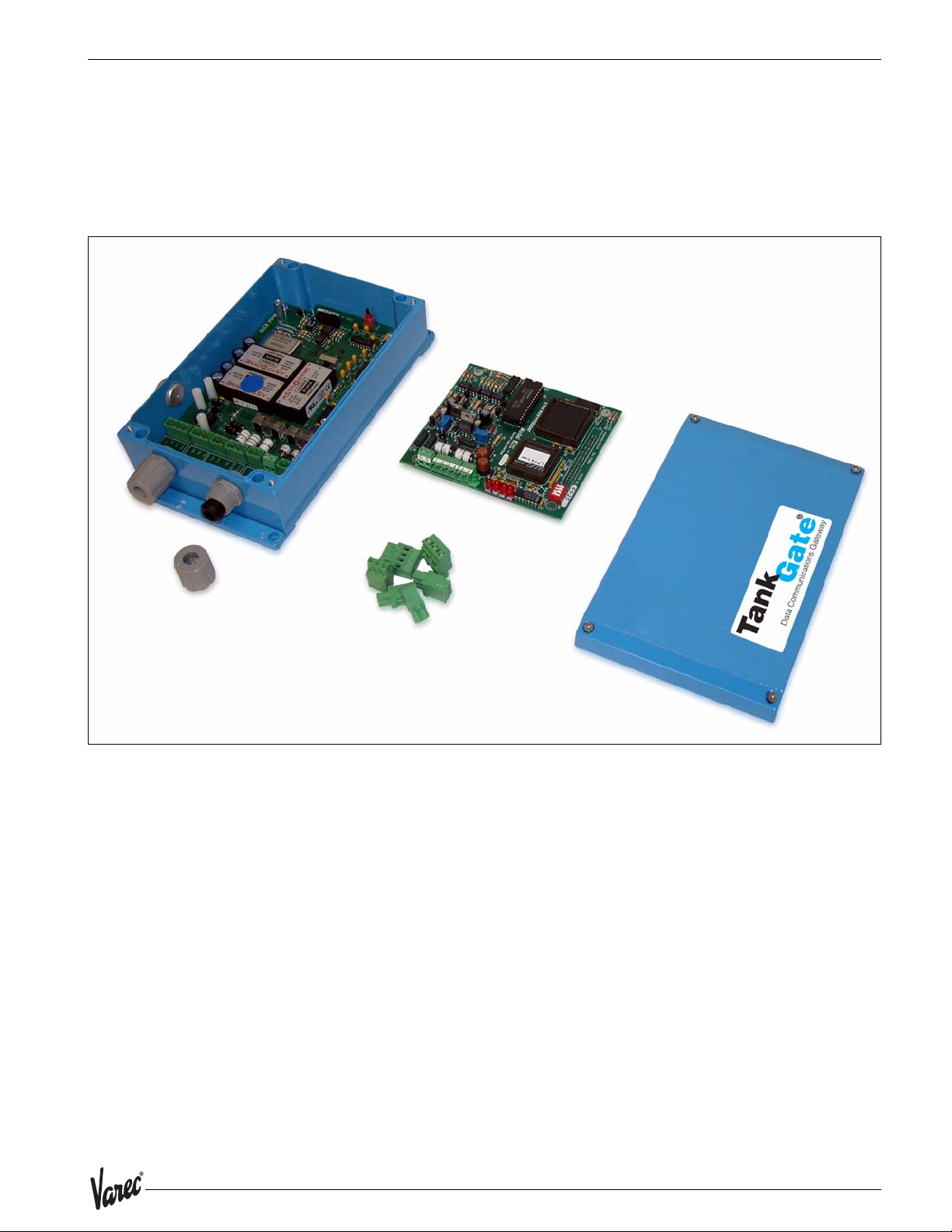
The TankGate consists of an enclosure, motherboard, single tank gauge interface module
and connectors.
Figure 2-1: TankGate hardware components
5
Hardware TankGate Interface
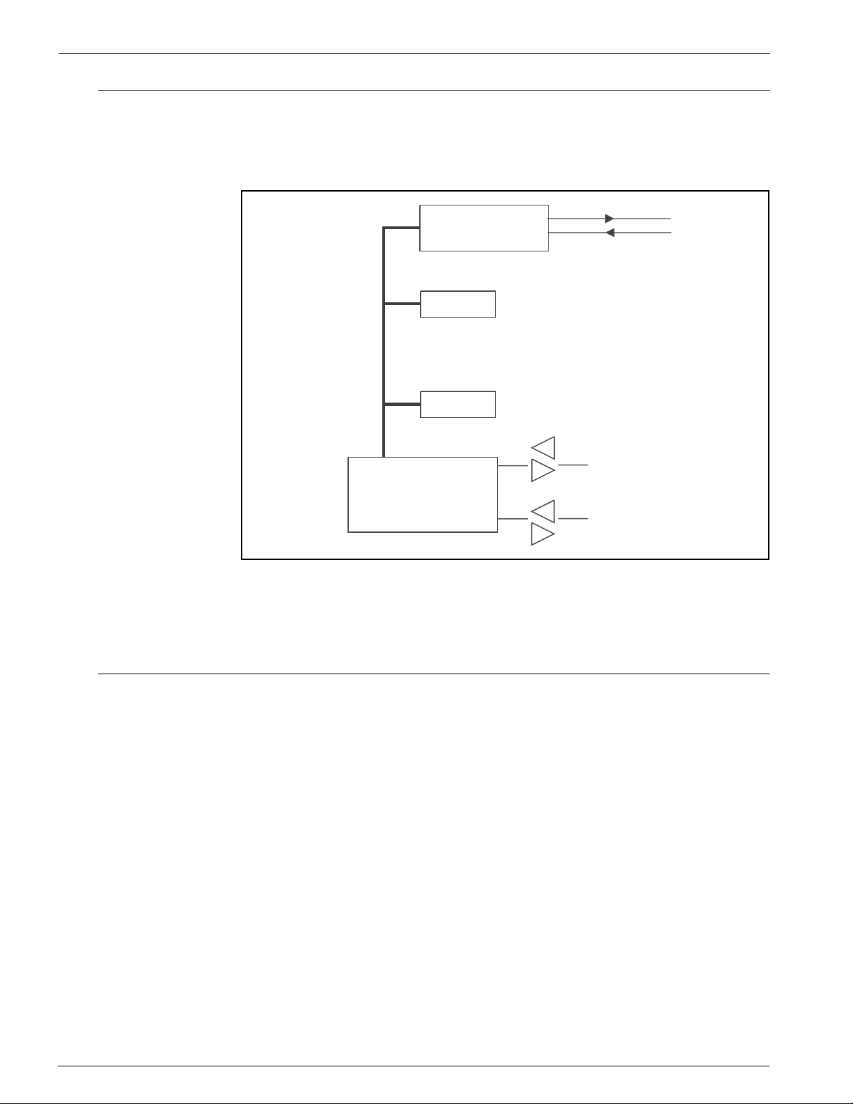
2.1 Hardware Block Diagram
A TankGate hardware functional block diagram is shown below. This diagram shows the
relationship between major subsystems and components in the TankGate.
Figure 2-2: TankGate functional block diagram
Tank Gauge
Interface Circuitry
The heart of the TankGate is an Intel 80C188EB microprocessor operating at 18.432
MHz. Designed specifically for real-time embedded applications, the µP includes timer/
counters, an interrupt controller, and chip-select circuitry. It also includes 2 serial
channels that are designated as COM0 and COM1.
2.2 Motherboard Description
uP
NOVRAM
PROM
Serial 1
Serial 0
128 K
256 k
COM 1
RS-232/RS-485
COM 0
RS-232
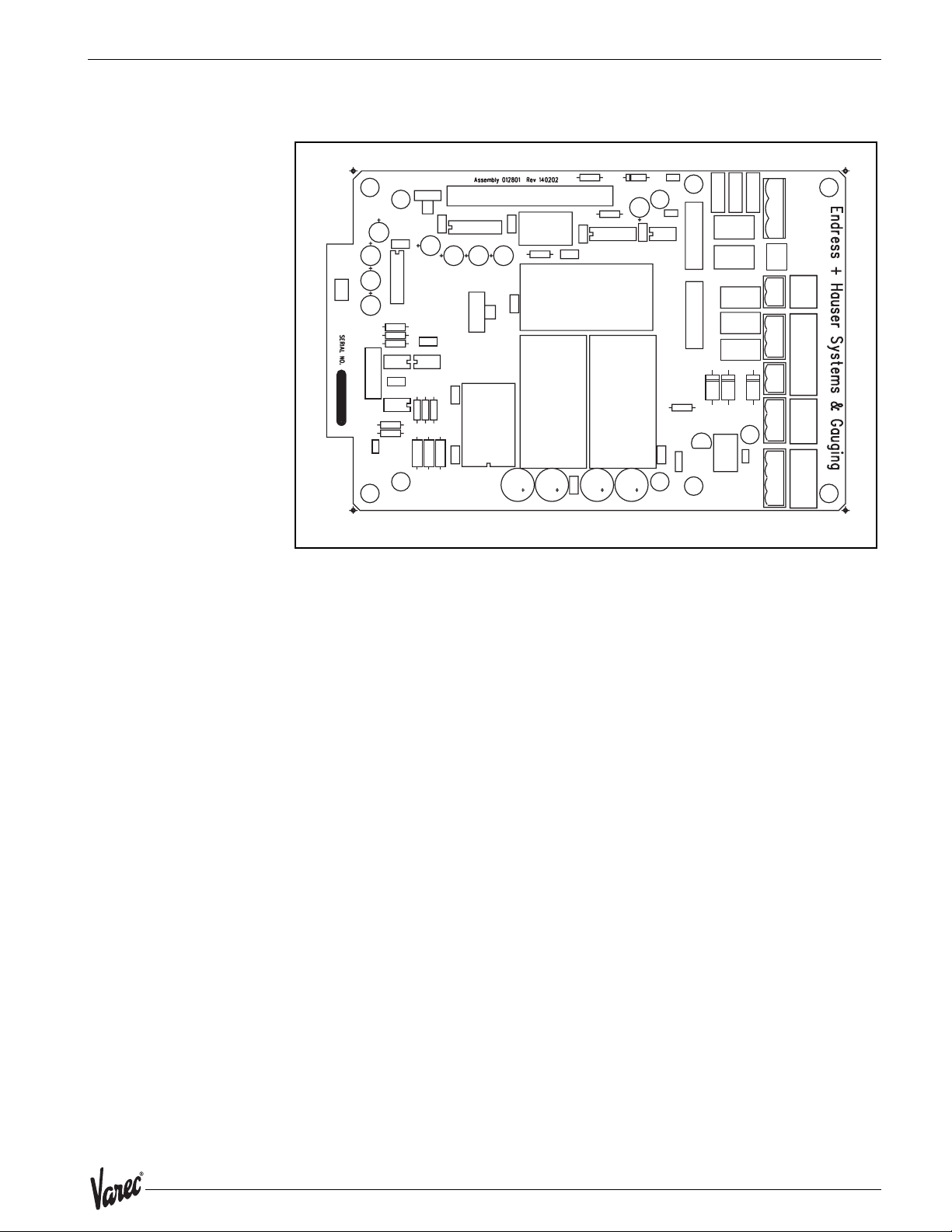
The motherboard description is broken into three sections. Each section identifies the
location of the components on the motherboard. When necessary, a brief description of
the component is provided. These sections are listed below:
• Power Supply
• Switches and Indicators
6 Installation and Operations Manual
8300 Hardware
• Communications
Figure 2-3: The TankGate motherboard
RESET
2.2.1 Power Supply
HARDWARE HANDSHAKING
A
EARTH
B
RS232
COM1
RS485
VFIELD=48V
VFIELD=24V
NEUTRAL
LINE
SURGE GND
+
-
A/TXD
B/RXD
GND
RTS
CTS
TXD
RXD
GND
+15V
+5V
GND
-15V
VFIELD
COM1
COM 0 AUX POWER
• Unit AC Power terminal block (J2)
• Surge Protection terminal block (J4)
• Field Power terminal block (J3)
• Auxiliary DC Power Output terminal block (J8)
• AC Power fuses (500 mA - 250V 5x20 mm) (F1, F2)
• Field Voltage Selection Jumper (W3)
7
Hardware TankGate Interface
AUX POWER
EARTH
NEUTRAL
LINE
SURGE GND
+
VFIELD
LINE
SURGE GND
A/TXD
B/RXD
GND
+
-
VFIELD
COM1
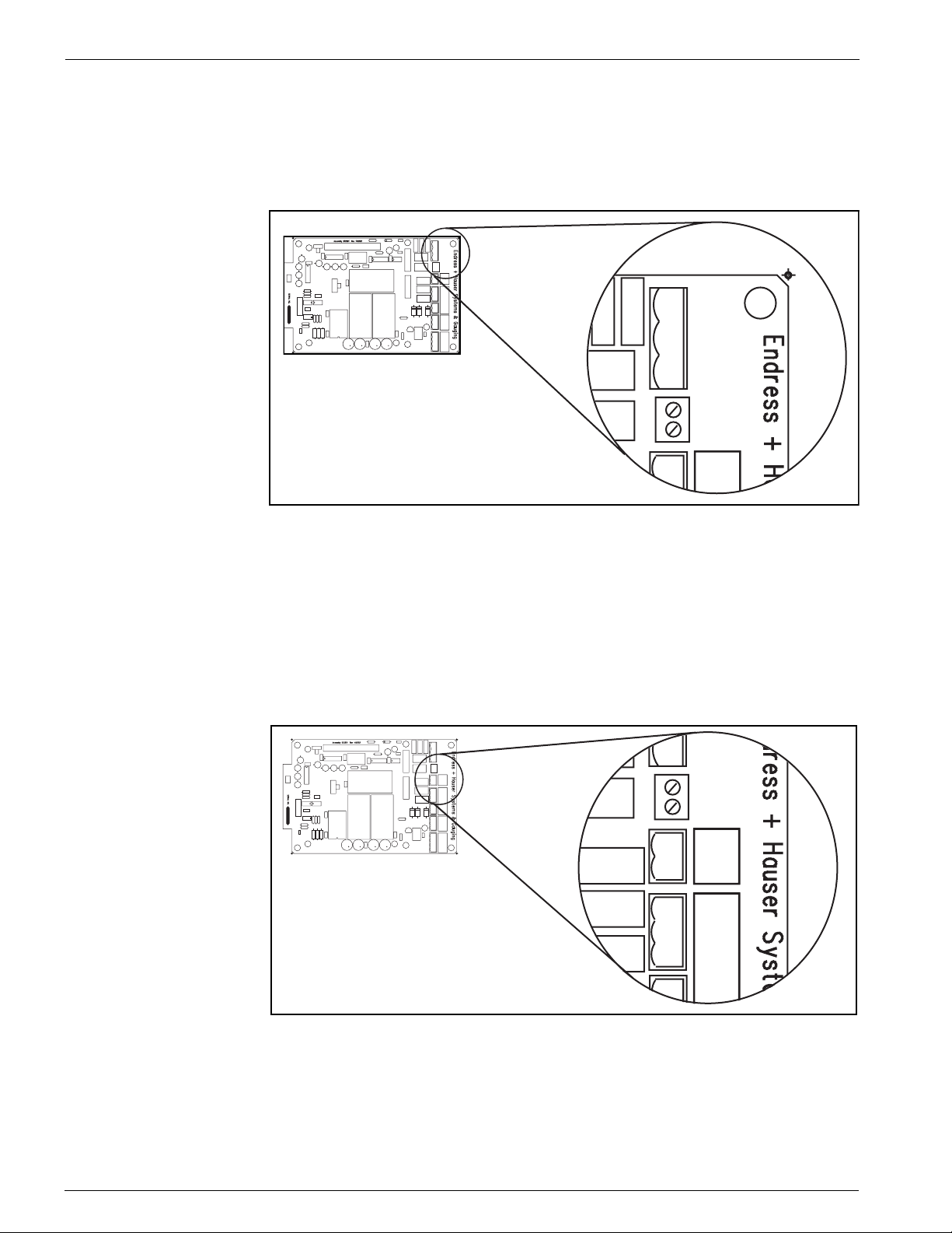
2.2.1.1 Unit AC Input Power terminal block (J2)
The Unit AC power terminal block is used to provide AC power to the TankGate. The
power requirements for the TankGate are 100-240 VAC, 50/60 Hz. The AC Input Power
terminal block is shown in the figure below:
Figure 2-4: AC Input terminal block
HARDWARE HANDSHAKING
A
B
RESET
RS232
COM1
RS485
EARTH
NEUTRAL
LINE
SURGE GND
VFIELD
+
-
A/TXD
B/RXD
COM1
GND
RTS
CTS
TXD
COM 0 AUX POWER
RXD
GND
VFIELD=48V
+15V
VFIELD=24V
+5V
GND
-15V
J2
J4
2.2.1.2 Surge Protection (Surge Gnd) terminal block (J4)
The Surge Gnd terminal block is used to connect the surge protection components (gas
tubes, MOVs) to earth ground. Ensure there is a low impedence path (< 1ohm) to earth
ground (a ground rod or grounding system).
2.2.1.3 Field Power (VFIELD) terminal block (J3)
The Field Power terminal block, referred to as VFIELD, is used to provide power for field
instruments. The output is configurable using jumpers (Jumper W3, discussed below).
Figure 2-5: field Power terminal block
HARDWARE HANDSHAKING
A
B
RESET
RS232
COM1
RS485
2.2.1.4 Auxiliary DC Output Power terminal block (J8)
The Auxiliary power terminal block is used when external equipment must be powered
from the TankGate’s internal power supply. The triple output power supply provides +5,
8 Installation and Operations Manual
EARTH
NEUTRAL
LINE
SURGE GND
VFIELD
+
-
A/TXD
B/RXD
COM1
GND
RTS
CTS
TXD
COM 0 AUX POWER
RXD
GND
VFIELD=48V
+15V
VFIELD=24V
+5V
GND
-15V
J3
J4
8300 Hardware
CTS
TXD
RXD
GND
+15V
+5V
GND
-15V
COM 0 AUX POWER
J8
J7
+15 and -15 Volts. These are rated 210 mA, 50 mA, and 5 mA, respectively. The DC
Power terminal block is shown below:
Figure 2-6: DC Input voltage terminal block
HARDWARE HANDSHAKING
A
B
RESET
RS232
COM1
RS485
EARTH
NEUTRAL
LINE
SURGE GND
VFIELD
+
-
A/TXD
B/RXD
COM1
GND
RTS
CTS
TXD
COM 0 AUX POWER
RXD
GND
VFIELD=48V
+15V
VFIELD=24V
+5V
GND
-15V
2.2.1.5 AC Power Fuses (F1,F2)
The AC Power Fuses provide protection for the AC input power. The two fuses, F1 and
F2, are rated at 500 mA, 250 V.
Figure 2-7: AC Power Fuse
F1
HARDWARE HANDSHAKING
A
B
RESET
RS232
COM1
RS485
EARTH
NEUTRAL
LINE
SURGE GND
VFIELD
+
-
A/TXD
B/RXD
COM1
GND
RTS
CTS
TXD
COM 0 AUX POWER
RXD
GND
VFIELD=48V
+15V
VFIELD=24V
+5V
GND
-15V
F2
2.2.1.6 Field Voltage Selection Jumper (W3)
The Field Voltage Selection Jumper W3 determines the voltage available at the VFIELD
terminals (J3). The Field Voltage can be configured for +24 VDC or +48VDC. At +24VDC,
9
Hardware TankGate Interface
VFIELD=48V
VFIELD=24V
J8
J7
RESET
there is 230 mA of field power available. At +48VDC, there is 230 mA of field power
available.
Figure 2-8: Selection Jumper W3
HARDWARE HANDSHAKING
A
B
RESET
RS232
COM1
RS485
VFIELD=48V
VFIELD=24V
2.2.2 Switches and Indicators
2.2.2.1 Reset push-button (SW3)
The RESET Switch is used to re-initialize the system hardware by causing it to go to a
known starting state. This switch may be pressed at any time; however, it will do the
following:
• Re initialize System Hardware
• Clear Scratch Memory
• Verify Database and Re initialize if Invalid
• Reset All Timers
• Enable Communications
EARTH
NEUTRAL
LINE
SURGE GND
VFIELD
+
-
A/TXD
B/RXD
COM1
GND
RTS
CTS
TXD
COM 0 AUX POWER
RXD
GND
+15V
+5V
GND
-15V
W3
Figure 2-9: Switches SW3 on the TankGate motherboard
HARDWARE HANDSHAKING
A
B
RESET
RS232
COM1
RS485
EARTH
NEUTRAL
LINE
SURGE GND
VFIELD
+
-
A/TXD
B/RXD
COM1
GND
RTS
CTS
TXD
COM 0 AUX POWER
RXD
GND
VFIELD=48V
+15V
VFIELD=24V
+5V
GND
-15V
SW3
Hard Reset
A special form of Reset is available for occasions when the battery backed-up data base
must be re initialized. This type of reset, the Hard Reset, can be performed before a
database is downloaded from a host PC.
Caution! The Hard Reset should be used as a last resort if the TankGate is not functioning. A
Hard reset clears the installed database. For the Hard Reset procedure, refer to the
Troubleshooting and Maintenance chapter.
10 Installation and Operations Manual
8300 Hardware
A/TXD
B/RXD
GND
RTS
CTS
TXD
RXD
GND
+15V
+
-
VFIELD
COM1
COM 0 AUX POW
J7
CTS
TXD
RXD
GND
+15V
+5V
GND
-15V
COM 0 AUX POWER
J8
J7
2.2.3 Communications
The Communications installation requires connection of the appropriate communication
cable to one of two connectors. The available options include RS-232 and RS-485
communications.
• COM0 (RS-232) (J7)
• COM1 (RS-232 or RS-485) (J5)
• COM1 Transmit Control (RS-232) (J6)
• COM1 Hardware Handshaking Switch (SW1)
• COM1 RS-232/RS-485 Selection Switch (SW2)
• COM1 RS-485 Terminating Resistor Jumper (W2)
Figure 2-10:Com1 J5 Terminal Block
HARDWARE HANDSHAKING
A
B
RESET
RS232
COM1
RS485
EARTH
NEUTRAL
LINE
SURGE GND
VFIELD
+
-
A/TXD
B/RXD
COM1
GND
RTS
CTS
TXD
COM 0 AUX POWER
RXD
GND
VFIELD=48V
+15V
VFIELD=24V
+5V
GND
-15V
J5
J6
2.2.3.1 COM0 (J7)
COM0 is an RS-232 port for use in diagnostic testing/local programming or
communications to a host system. The
protocol defaults to TankGate Slave at the 9600 baud, 8 data bits, and no parity (for use
with ViewRTU or FuelsManager).
Figure 2-11:Com 0 J7 Terminal Block
HARDWARE HANDSHAKING
A
B
RESET
RS232
COM1
RS485
EARTH
NEUTRAL
LINE
SURGE GND
VFIELD
+
-
A/TXD
B/RXD
COM1
GND
RTS
CTS
TXD
COM 0 AUX POWER
RXD
GND
VFIELD=48V
+15V
VFIELD=24V
+5V
GND
-15V
11
Hardware TankGate Interface
RS232
RS485
COM1
HARDWARE HANDSHAKING
A
B
2.2.3.2 COM1 (RS-232/RS-485) (J5)
Note! On some versions of the TankGate, COM1 is not available
RS-232 is one of the two types of high-speed serial communications channels available
to interface to Host systems using several different protocols. RS-232 will operate at
distances up to 100 feet, while RS-485 allows multidrop communications at distances
up to 4000 feet. RS-232 can be used for flexibility in configuring other types of
communications links. Other variations of RS-232 communications interfaces include
radio, modem and fiber optic interfaces.
The choice of RS-232 or RS-485 is determined by the COM RS-232/RS-485 Selection
Switch SW2
2.2.3.3 COM1 RS232/RS-485 Selection Switch (SW2)
Switch SW2 determines whether RS-232 or RS485 is used. Note that the Hardware
Handshaking Switch SW1 affects the operation of COM1
Figure 2-12:Com1 SW2 Switch
HARDWARE HANDSHAKING
A
B
RESET
RS232
COM1
RS485
EARTH
NEUTRAL
LINE
SURGE GND
VFIELD
+
-
A/TXD
B/RXD
COM1
GND
RTS
CTS
TXD
COM 0 AUX POWER
RXD
GND
VFIELD=48V
+15V
VFIELD=24V
+5V
GND
-15V
SW2
2.2.3.4 COM1 Hardware Handshaking Switch (SW1)
For RS-232, there are two different settings. One setting is used if hardware
handshaking (RTS/CTS) is required. The other setting eliminates the need for hardware
handshaking. Set the Hardware Handshaking Switch to the ‘A’ position to use RTS/CTS
when a modem or signal converter is involved and requires RTS/CTS to operate. The RTS
and CTS signals will be available on terminal block J6. If the connection is direct using
RS-232, jumper RTS to CTS by setting SW1 to the ‘B’ position
Figure 2-13:Com1 SW1 Switch
HARDWARE HANDSHAKING
A
B
RESET
RS232
COM1
RS485
EARTH
NEUTRAL
LINE
SURGE GND
VFIELD
+
-
A/TXD
B/RXD
COM1
GND
RTS
CTS
TXD
COM 0 AUX POWER
RXD
GND
VFIELD=48V
+15V
VFIELD=24V
+5V
GND
-15V
SW1
12 Installation and Operations Manual
8300 Hardware
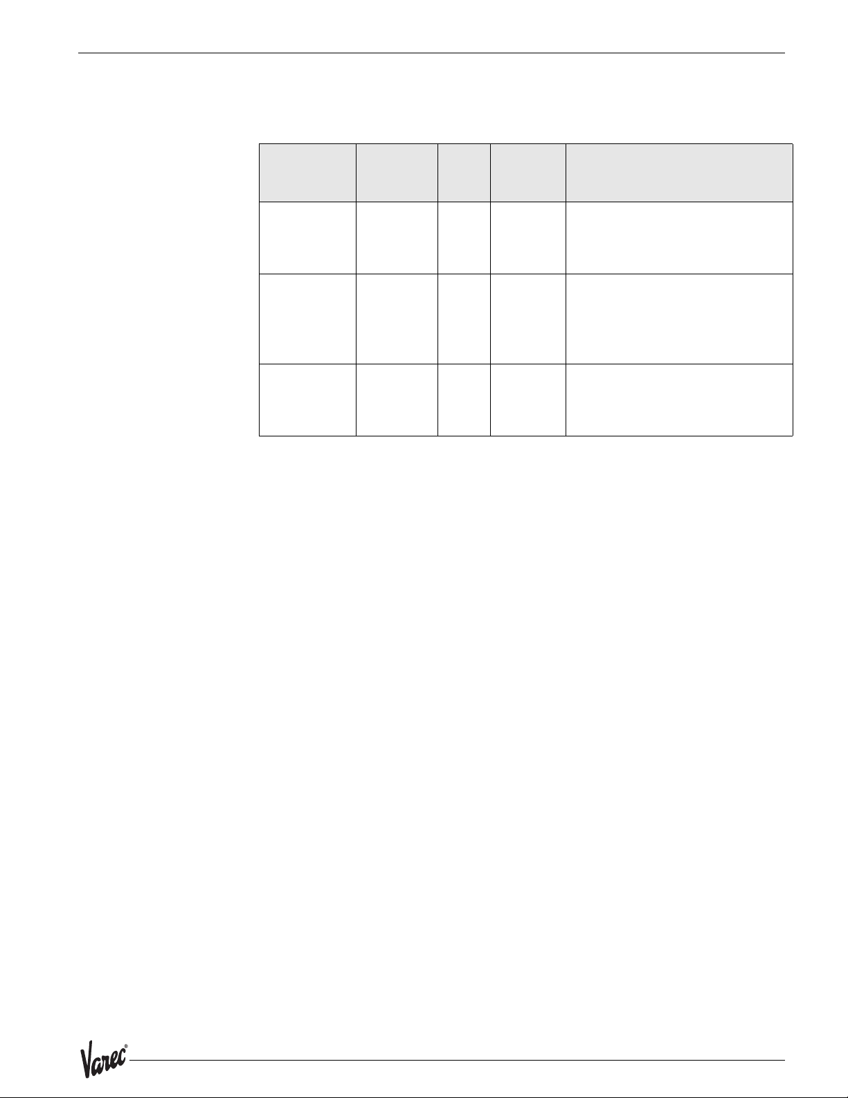
For RS-485, set the Hardware Handshaking Switch SW1 to the ‘A’ position. Refer to the
following table:
Communication Physical
Layer
RS-232
RS-232
RS-485
Hardware
Handshaking
SW1
Setting
SW2 Setting
No A UP
(towards
the RS232 side)
Yes B UP
(towards
the RS232 side)
Yes A DOWN
(towards
the RS485 side)
Notes
Use with a PC. Signals at terminal
block J5 will be RS-232
Use to communicate to systems that
require Request To Send (RTS) in order
to transmit (Modems, Radios, etc.)
RTS and CTS signals will be available at
terminal block J6
Always SW1 set to the A position when
using RS-485..
13
Hardware TankGate Interface
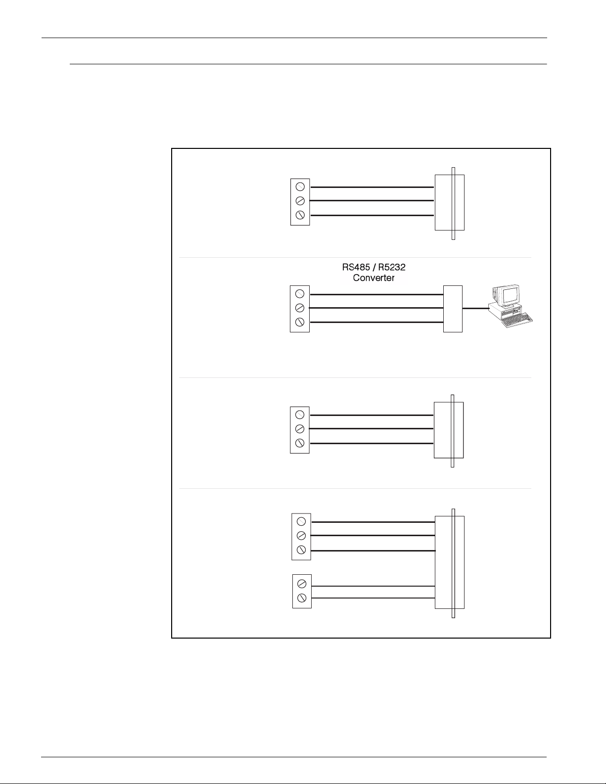
2.3 TankGate Communications Cable
The layout for the RS-232 cable between the PC and the TankGate is shown in the
following illustrations
Figure 2-14:Com 1 Cable without RTS/CTS
PC
Com 0
(RS-232)
Com 1
(RS485)
TANK GATE
TXD
RXD
GND
J7
TANK GATE
A
B
GND
J6
2
3
5
DB9 Female
R5485 / R5238
Converter
A
B
GND
Pin Signal
RXD
2
TXD
3
GND
5
PC
Com 1
without RTS / CTS
(RS-232)
Com 1
with RTS / CTS
(RS-232)
NOTE! Signals on RS485 / RS232 converter may have different designations.
Refer to OFM manual for the converter for more information.
PC
TANK GATE
TXD
RXD
GND
J6
TANK GATE
TXD
RXD
GND
J6
RTS
CTS
J7
2
3
5
DB9 Female
DCE
3
2
5
7
8
DB9 Male
Pin Signal
RXD
2
TXD
3
GND
5
Pin Signal
2
RXD
3
TXD
5
GND
78RTS
CTS
14 Installation and Operations Manual
8300 8315 L&J Tankway Interface Module
3 8315 L&J Tankway Interface Module
3.1 Features
• Supports up to 50 tanks
• Communicates using L&J Tankway protocol
• Interfaces to L&J Tankway compatible Tank Gauge transmitters
• ANSI/IEEE surge protection
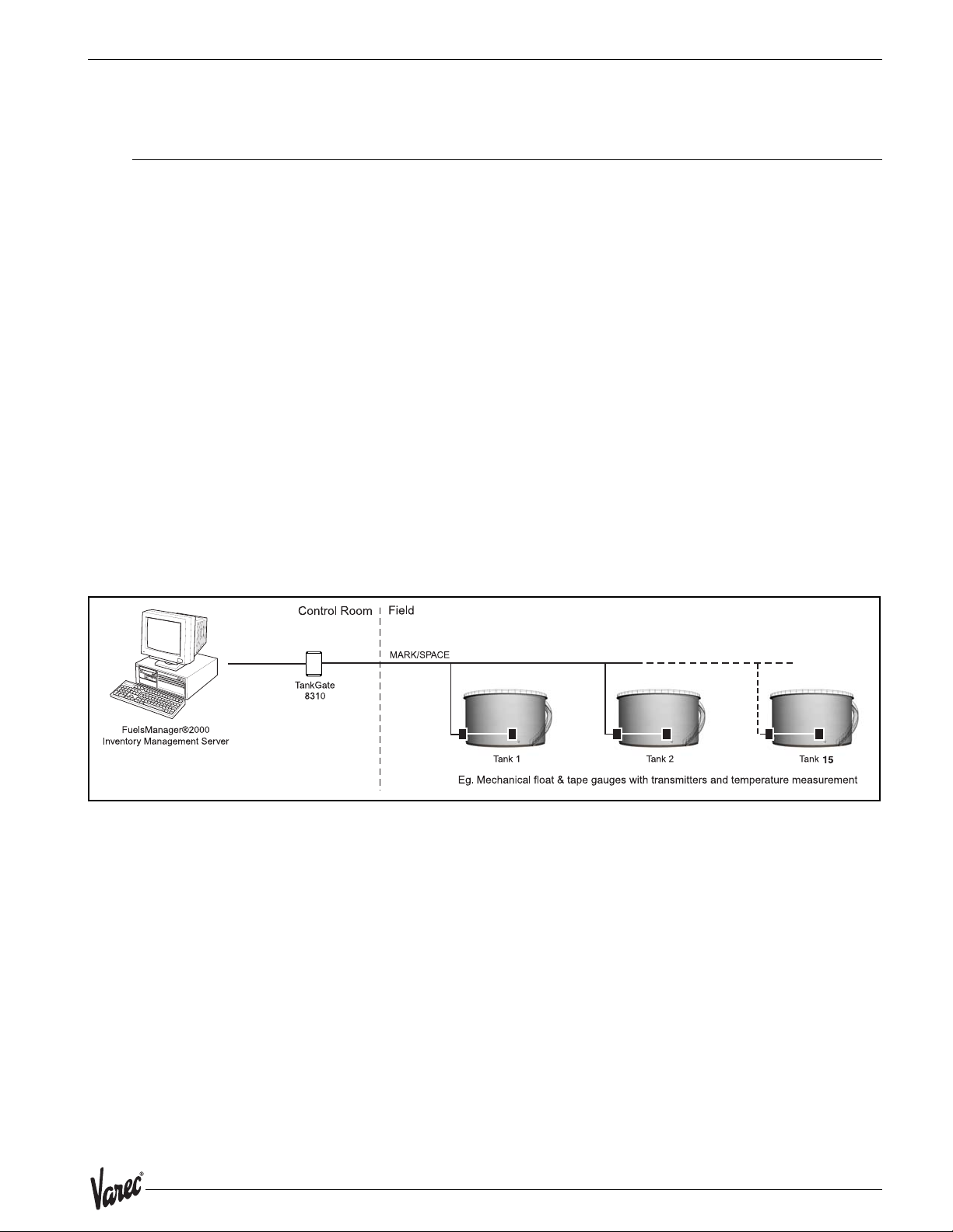
The Model 8215 interface with tank gauge transmitters uses Whessoe-Varec’s Mark/
Space protocol to communicate. There are a number of transmitters that are Mark/Space
compatible, including:
• L&J MCG 1000
• L&J MCG 1500
• L&J MCG 2000
Note! The 8315 TankGate uses the 8215 communications module.
The Model 8315 requires an external +48VDC power supply. It is also possible to use the
+48VDC power supply of the TankGate to power the tank gauge transmitters, if there are
fewer than 15 devices. The following figure illustrates how the Model 8315 appears when
installed on the TankGate.
Figure 3-1: Mark/Space Diagram
15
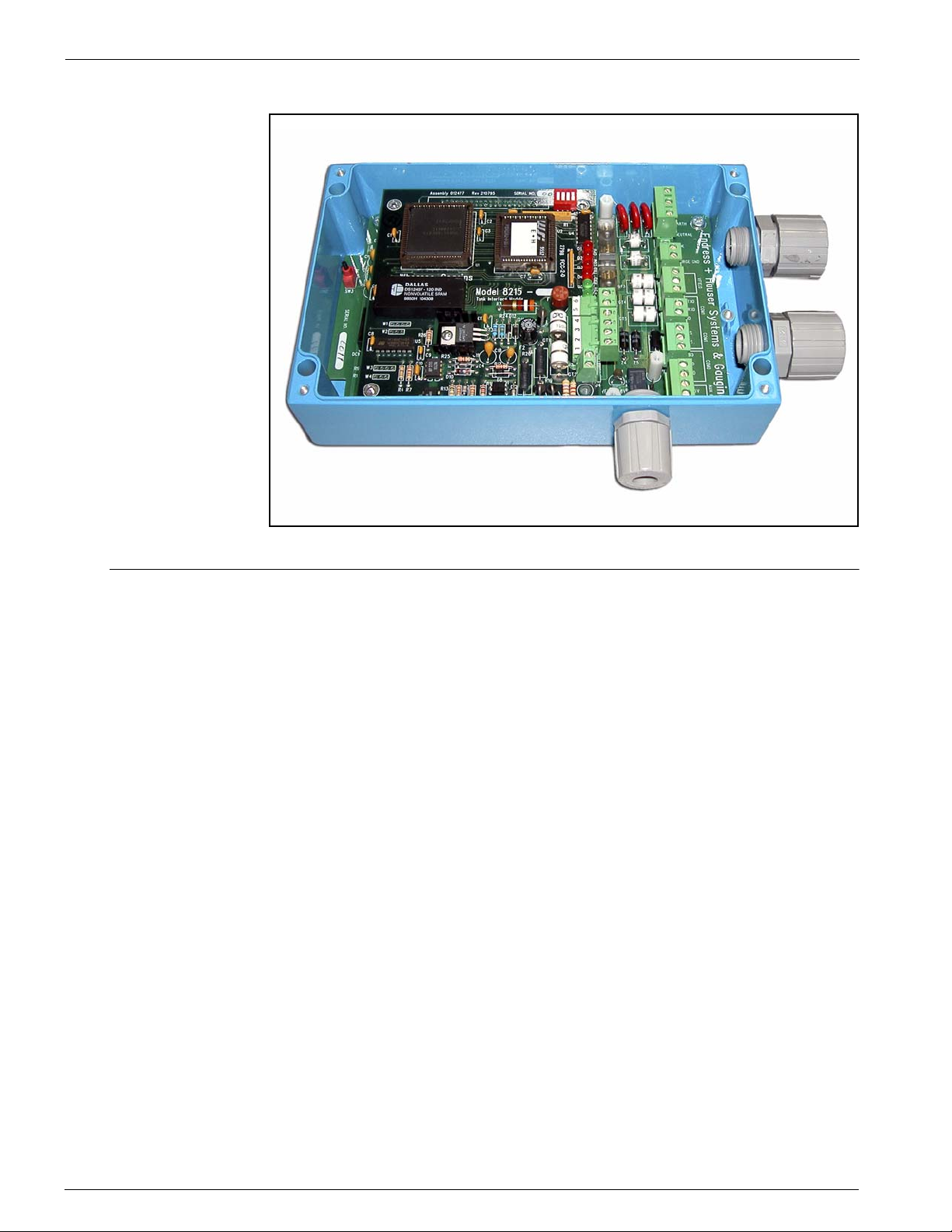
8315 L&J Tankway Interface Module TankGate Interface
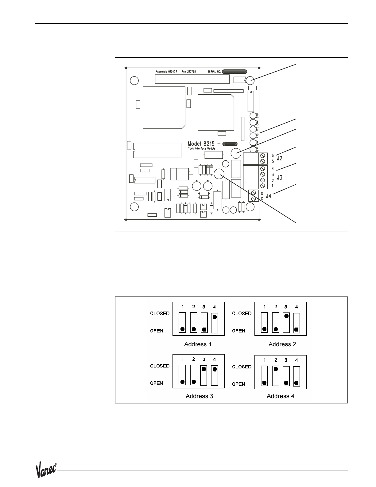
Figure 3-2: Model 8315 TankGate
3.2 Description
The components of the 8315 are illustrated in the following figure. This section explains
how to connect field wiring and to configure jumper settings.
• Unit ID DIP Switch (SW 1)
• LED Indicators (D1 - D5, D14)
• +48V Line fuse (1A 250V TR5) (F1)
• External Power Connector (+48V) (J2)
• Surge/Shield ground connector (J4)
•Field Wiring termination block (J3)
16 Installation and Operations Manual
8300 8315 L&J Tankway Interface Module
Figure 3-3: Model 8315 L&J Tankway Interface
ID DIP Switch (SW1)
LED indicators (D1 D6)
+48-65 VDC power fuse
(1 A 250V TR5) (F1)
External Power Connector
(+48 - 65 VDC) (J2)
Field wiring
terminal block (J3)
Surge/Shield
ground connector (J4)
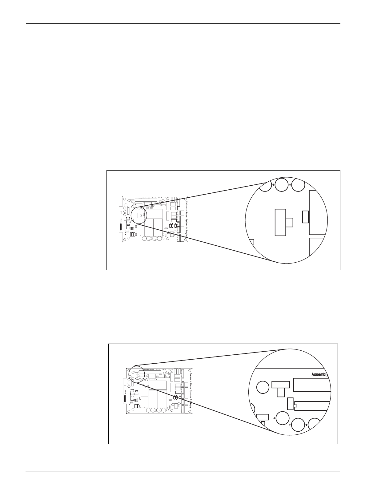
3.2.1 ID DIP Switch (SW1)
The ID DIP Switch is a binary switch that sets the unit ID number (1-4). This value is set
to the port number on which the Model 8315 is installed (e.g. P1=1). The switch is set
according to its location on the motherboard. Set to “1” for P1, “2” for P2, “3” for P3, and
“4” for P4. Refer to the following figures:
Figure 3-4: ID DIP Switch settings
Transmit Line Fuse
(63 mA 250V TR5) (F2)
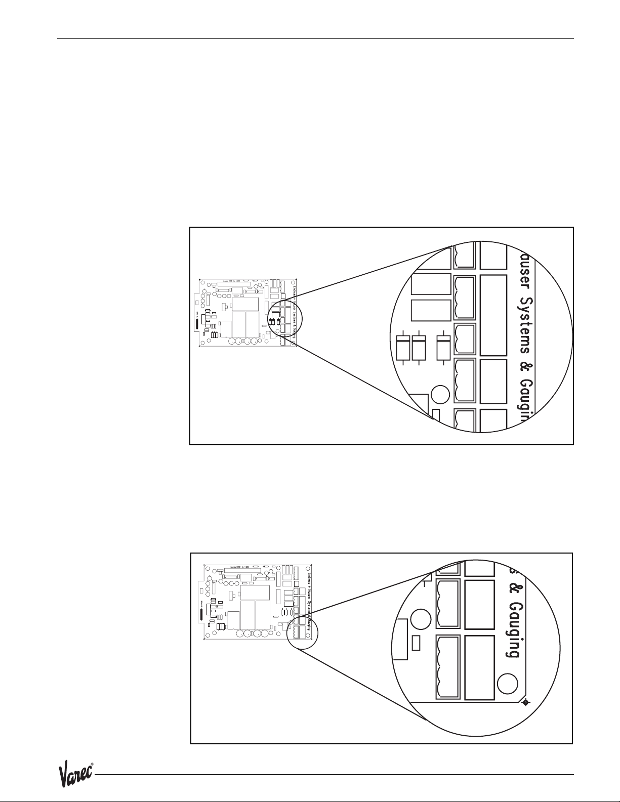
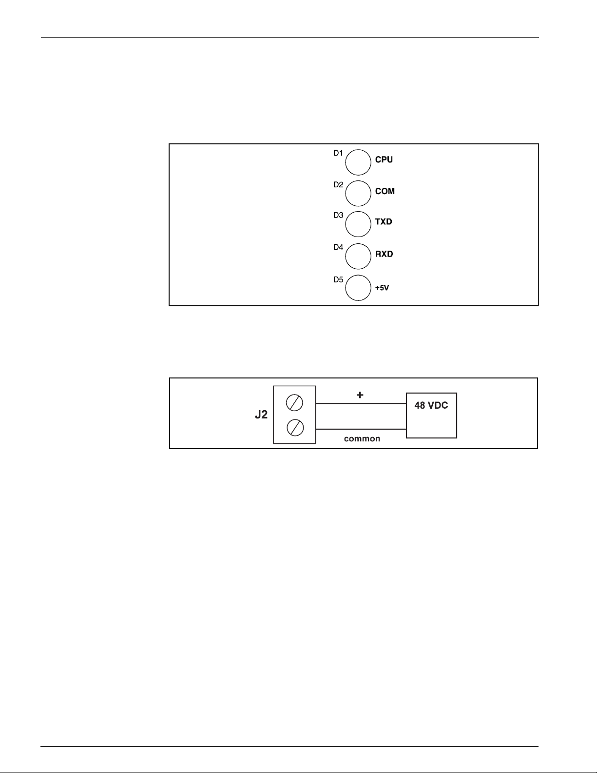
3.2.2 LED Indicators (D1-D6)
The LED displays indicate the status of the Model 8315’s CPU and communications. The
indicators are identified in the following figure.
• CPU: CPU activity
17
8315 L&J Tankway Interface Module TankGate Interface
• COM: Communication between the TankGate and the host computer
• TXD: Transmitting data to tank gauge
• RXD: Receiving data from tank gauge
• +5V: Indicates interface module power
• +VEXT: Indicates external power
Figure 3-5: Model 8315 LED Indicators
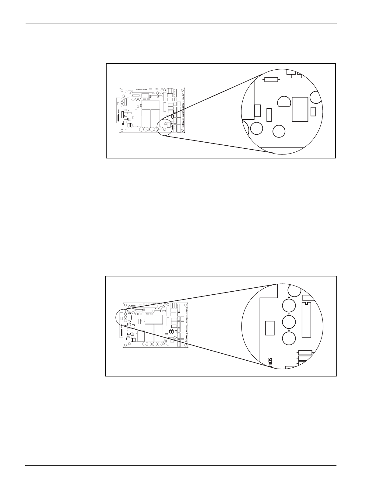
3.2.3 External Power Connector (+48V) (J2)
Connect the +48 VDC External Power as shown below:
Figure 3-6: External Power Connector
3.2.4 Surge/Shield Ground Connector (J4)
Connecting the Surge/Shield ground connector
Caution! This ground connection is important for system safety.
• Connect a 14 AWG copper wire between the ground terminal (J4) and a good
earth ground. Perform this step before connecting ANY other wires.
• Verify that the resistance in this connection does not exceed 1 ohm.
18 Installation and Operations Manual
8300 8315 L&J Tankway Interface Module
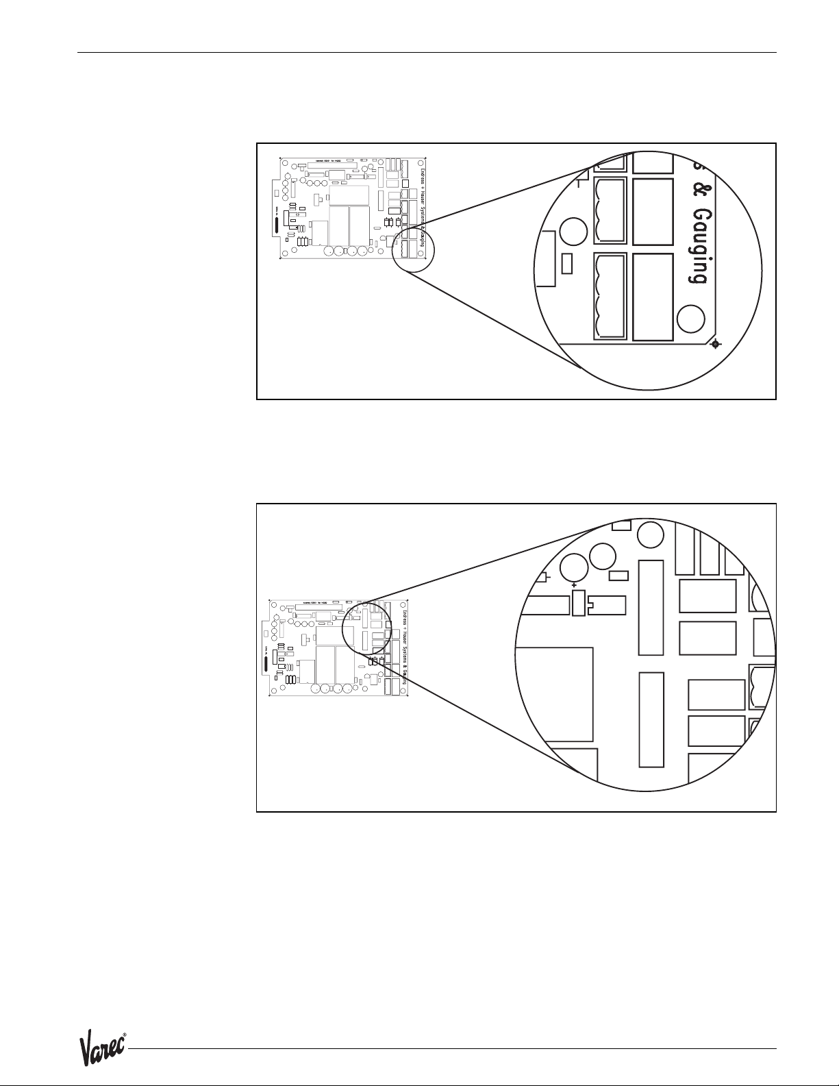
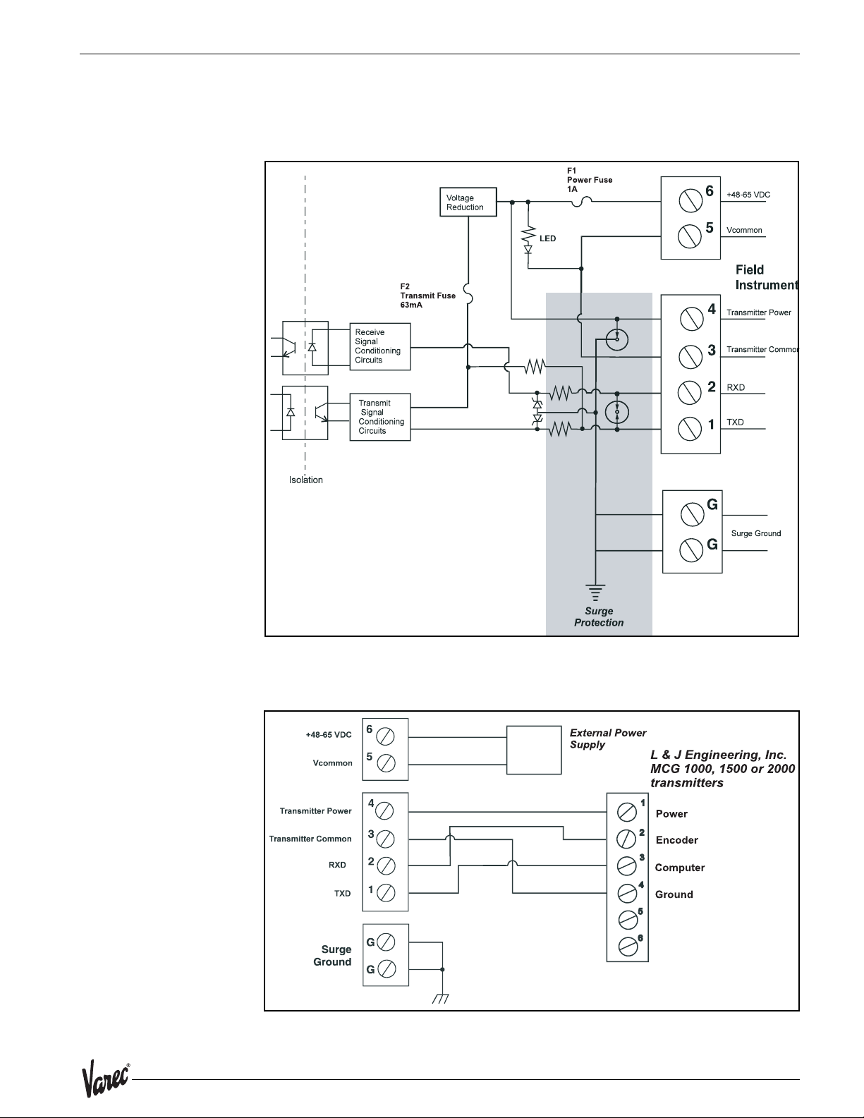
3.2.5 Field Wiring terminal block (J3)
A schematic illustrating the terminal connections of the Model 8315 is shown below:
Figure 3-7: Model 8315 Input Circuit
Connect the field wiring
• Connect the wiring following the diagram below.
Figure 3-8: L & J Engineering, Inc. MCG 1000, 1500 or 2000 transmitter
19

8315 L&J Tankway Interface Module TankGate Interface
20 Installation and Operations Manual
 Loading...