

Page 1

4532 Average Temperature Sensor and
Converter
Installation and
Operations Manual
For software version V1.45
IOM019NVAE0208
www.varec.com
5834 Peachtree Corners East, Norcross (Atlanta), GA 30092 USA
Tel: +1 (770) 447-9202 Fax: +1 (770) 662-8939
Varec, Inc.
Page 2

Page 3

4532
Copyright
All rights reserved. Printed in the United States of America. Except as permitted under
the United States Copyright Act of 1976, no part of this publication may be reproduced,
stored in a retrieval system or transmitted in any form or by any means- electronic,
mechanical, photocopying, recording or otherwise- without the prior written permission
of the Publisher:
Varec, Inc.
5834 Peachtree Corners East
Norcross (Atlanta) GA 30096
USA
Trademarks acknowledged
Varec, Inc. recognizes all other trademarks. Trademarks of other products mentioned in
this document are held by the companies producing them.
Varec® is a registered trademark of Varec, Inc., a wholly-owned subsidiary of
Science Applications International Corporation
Varec, Inc. 1
Page 4

Average Temperature/Water Bottom Sensor and Converter
Disclaimer of Warranties
The contract between the Seller and the Buyer states the entire obligation of the Seller.
The contents of this document shall not become part of or modify any prior or existing
agreement, commitment or relationship between the Seller and Buyer. There are no
express or implied warranties set out in this document. The only warranties that apply
are those in the existing contract between the Seller and Buyer.
Varec, Inc. products have not been tested by Varec, Inc. under all possible operational
conditions, and Varec, Inc. may not have all the data relative to your application. The
information in this document is not all inclusive and does not and cannot take into
account all unique situations. Consequently, the user should review this product
literature in view of his/her application. If you have any further questions, please contact
Varec, Inc. for assistance.
Limitations of Seller's Liability
In the event that a court holds that this document created some new warranties, Seller's
liability shall be limited to repair or replacement under the standard warranty clause. In
no case shall the Seller's liability exceed that stated as Limitations of Remedy in the
contract between the Seller and Buyer.
Terms of Use
The information provided in this document is provided “as is” without warranty of any
kind. Varec, Inc. disclaim all warranties, either express or implied, including the
warranties of merchantability and fitness for a particular purpose. In no event shall
Varec, Inc. or its suppliers be liable for any damages whatsoever including direct,
indirect, incidental, consequential, loss of business profits or special damages, even if
Varec, Inc. or its suppliers have been advised of the possibility of such damages.
Use of parts that are not manufactured or supplied by Varec, Inc. voids any Varec, Inc.
warranty and relieves Varec, Inc. of any obligation to service the product under warranty.
Varec, Inc. recommends the use of only Varec, Inc. manufactured or supplied parts to
maintain or service Varec, Inc. products.
Use of parts that are not manufactured or supplied by Varec, Inc. invalidates the agency
approval for this product.
2 Installation and Operations Manual
Page 5

4532
Safety Precaution Definitions
Caution! Damage to equipment may result if this precaution is disregarded.
Warning! Direct injury to personnel or damage to equipment which can cause injury to
personnel may result if this precaution is not followed.
Safety Precautions
Read and understand this instruction manual before installing, operating or performing
maintenance on the Varec 4532 Average Temperature Sensor and Converter. Follow all
precautions and warning noted herein when installing, operating or performing
maintenance on this equipment.
Varec, Inc. 3
Page 6

Average Temperature/Water Bottom Sensor and Converter
4 Installation and Operations Manual
Page 7

4532 Contents
Contents
1 Introduction. . . . . . . . . . . . . . . . . . . . . . . . . . . . . . . . . . . . . . . . . . . . . . . . 1
1.1 Introduction . . . . . . . . . . . . . . . . . . . . . . . . . . . . . . . . . . . . . . . . . . . . . . . . . . 1
1.2 Installation and operation overview . . . . . . . . . . . . . . . . . . . . . . . . . . . . . . . . 1
1.3 Software history. . . . . . . . . . . . . . . . . . . . . . . . . . . . . . . . . . . . . . . . . . . . . . . 1
1.4 System functional diagram. . . . . . . . . . . . . . . . . . . . . . . . . . . . . . . . . . . . . . . 2
2 Safety instructions. . . . . . . . . . . . . . . . . . . . . . . . . . . . . . . . . . . . . . . . . 3
2.1 Installation, commissioning and operation. . . . . . . . . . . . . . . . . . . . . . . . . . . 3
2.2 Product Requirements . . . . . . . . . . . . . . . . . . . . . . . . . . . . . . . . . . . . . . . . . . 3
2.2.1 Power source. . . . . . . . . . . . . . . . . . . . . . . . . . . . . . . . . . . . . . . . . . . . . 3
2.2.2 Use in hazardous areas. . . . . . . . . . . . . . . . . . . . . . . . . . . . . . . . . . . . . . 3
2.2.3 External connection . . . . . . . . . . . . . . . . . . . . . . . . . . . . . . . . . . . . . . . . 3
2.3 Operational safety . . . . . . . . . . . . . . . . . . . . . . . . . . . . . . . . . . . . . . . . . . . . . 3
2.3.1 Hazardous area . . . . . . . . . . . . . . . . . . . . . . . . . . . . . . . . . . . . . . . . . . . 3
2.3.2 Power supply . . . . . . . . . . . . . . . . . . . . . . . . . . . . . . . . . . . . . . . . . . . . . 4
2.3.3 Grounding . . . . . . . . . . . . . . . . . . . . . . . . . . . . . . . . . . . . . . . . . . . . . . . 4
2.3.4 Wiring . . . . . . . . . . . . . . . . . . . . . . . . . . . . . . . . . . . . . . . . . . . . . . . . . . 4
2.4 Return . . . . . . . . . . . . . . . . . . . . . . . . . . . . . . . . . . . . . . . . . . . . . . . . . . . . . . 4
2.5 Disposal. . . . . . . . . . . . . . . . . . . . . . . . . . . . . . . . . . . . . . . . . . . . . . . . . . . . . 4
2.6 Notes on safety conventions and symbols. . . . . . . . . . . . . . . . . . . . . . . . . . . 5
3 Identification. . . . . . . . . . . . . . . . . . . . . . . . . . . . . . . . . . . . . . . . . . . . . . . 7
3.1 Device designation. . . . . . . . . . . . . . . . . . . . . . . . . . . . . . . . . . . . . . . . . . . . . 7
3.1.1 Nameplate. . . . . . . . . . . . . . . . . . . . . . . . . . . . . . . . . . . . . . . . . . . . . . . 7
3.2 Scope of delivery . . . . . . . . . . . . . . . . . . . . . . . . . . . . . . . . . . . . . . . . . . . . . . 7
3.3 CE marks, declaration of conformity . . . . . . . . . . . . . . . . . . . . . . . . . . . . . . . 8
4 Installation. . . . . . . . . . . . . . . . . . . . . . . . . . . . . . . . . . . . . . . . . . . . . . . . . 9
4.1 Design, dimensions . . . . . . . . . . . . . . . . . . . . . . . . . . . . . . . . . . . . . . . . . . . . 9
4.2 Unpacking . . . . . . . . . . . . . . . . . . . . . . . . . . . . . . . . . . . . . . . . . . . . . . . . . . 10
4.3 Flexible tube. . . . . . . . . . . . . . . . . . . . . . . . . . . . . . . . . . . . . . . . . . . . . . . . . 10
4.4 Installation Instructions . . . . . . . . . . . . . . . . . . . . . . . . . . . . . . . . . . . . . . . . 11
4.5 Special conditions for safe use . . . . . . . . . . . . . . . . . . . . . . . . . . . . . . . . . . 11
5 Mounting . . . . . . . . . . . . . . . . . . . . . . . . . . . . . . . . . . . . . . . . . . . . . . . . . 13
5.1 Mounting instruction. . . . . . . . . . . . . . . . . . . . . . . . . . . . . . . . . . . . . . . . . . . 13
5.2 Mounting on a fixed roof tank. . . . . . . . . . . . . . . . . . . . . . . . . . . . . . . . . . . . 14
5.2.1 Top anchor method. . . . . . . . . . . . . . . . . . . . . . . . . . . . . . . . . . . . . . . . 14
5.2.2 Thermo well method . . . . . . . . . . . . . . . . . . . . . . . . . . . . . . . . . . . . . . . 16
Varec, Inc. 1
Page 8

Contents Average Temperature/Water Bottom Sensor and Converter
5.2.3 Anchor weight method . . . . . . . . . . . . . . . . . . . . . . . . . . . . . . . . . . . . . 17
5.3 Mounting on a floating roof tank . . . . . . . . . . . . . . . . . . . . . . . . . . . . . . . . . 19
5.3.1 Top anchor method . . . . . . . . . . . . . . . . . . . . . . . . . . . . . . . . . . . . . . . 19
5.3.2 Thermo well method. . . . . . . . . . . . . . . . . . . . . . . . . . . . . . . . . . . . . . . 20
5.3.3 Guide ring and anchor weight method . . . . . . . . . . . . . . . . . . . . . . . . . . 21
6 Wiring. . . . . . . . . . . . . . . . . . . . . . . . . . . . . . . . . . . . . . . . . . . . . . . . . . . . 23
6.1 Terminal Connection. . . . . . . . . . . . . . . . . . . . . . . . . . . . . . . . . . . . . . . . . . 23
6.1.1 4532 ATC terminal. . . . . . . . . . . . . . . . . . . . . . . . . . . . . . . . . . . . . . . . 23
6.1.2 6000 Series Servo Tank Gauge terminal . . . . . . . . . . . . . . . . . . . . . . . . 24
6.1.3 4590 TSM i.s. terminal . . . . . . . . . . . . . . . . . . . . . . . . . . . . . . . . . . . . . 24
6.2 Grounding . . . . . . . . . . . . . . . . . . . . . . . . . . . . . . . . . . . . . . . . . . . . . . . . . . 25
7 Operating. . . . . . . . . . . . . . . . . . . . . . . . . . . . . . . . . . . . . . . . . . . . . . . . . 27
7.1 Local HART connection . . . . . . . . . . . . . . . . . . . . . . . . . . . . . . . . . . . . . . . 27
7.1.1 As a Varec tank gauging instrument. . . . . . . . . . . . . . . . . . . . . . . . . . . . 27
7.1.2 As a standalone generic HART instrument . . . . . . . . . . . . . . . . . . . . . . . 27
7.2 Device set up: 4590 TSM . . . . . . . . . . . . . . . . . . . . . . . . . . . . . . . . . . . . . . 27
7.2.1 HART scanner. . . . . . . . . . . . . . . . . . . . . . . . . . . . . . . . . . . . . . . . . . . 27
7.2.2 The 4532 ATC specific parameter set up on the 4590 TSM . . . . . . . . . . . 28
7.3 Device set up: 6000 Series Servo Tank Gauge . . . . . . . . . . . . . . . . . . . . . 28
7.3.1 Preparation of 6000 Series Servo Tank Gauge . . . . . . . . . . . . . . . . . . . . 28
7.3.2 4532 ATC configuration on 6000 Series Servo Tank Gauge . . . . . . . . . . . 28
8 Operation and Description of Instrument Function . . . . . . . 31
8.0.1 HART Device designation. . . . . . . . . . . . . . . . . . . . . . . . . . . . . . . . . . . 31
8.0.2 Device Data . . . . . . . . . . . . . . . . . . . . . . . . . . . . . . . . . . . . . . . . . . . . 31
8.1 Temperature measurement . . . . . . . . . . . . . . . . . . . . . . . . . . . . . . . . . . . . 31
8.1.1 Primary values: VH00 ~ VH09. . . . . . . . . . . . . . . . . . . . . . . . . . . . . . . . 31
8.1.2 Element Temperature 1: VH10 ~ VH15 . . . . . . . . . . . . . . . . . . . . . . . . . 32
8.1.3 Element Temperature 2: VH20 ~ VH29 . . . . . . . . . . . . . . . . . . . . . . . . . 32
8.1.4 Element Position 1: VH30 ~ VH35
(VH36~VH39 is used only in 4539 ATC)
8.1.5 Element Position 2: VH40 ~ VH45 are not available in 4532 ATC . . . . . . . 35
8.1.6 WB primary and Advanced temp: VH50 ~ VH59 . . . . . . . . . . . . . . . . . . . 37
8.1.7 WB Adjustment and Operation Power: VH60 ~ VH69 . . . . . . . . . . . . . . . 38
8.1.8 Temperature Adjustment: VH70 ~ VH79. . . . . . . . . . . . . . . . . . . . . . . . . 38
8.1.9 Device setting 2: VH90~VH99. . . . . . . . . . . . . . . . . . . . . . . . . . . . . . . . 43
35
9 Maintenance. . . . . . . . . . . . . . . . . . . . . . . . . . . . . . . . . . . . . . . . . . . . . . 45
9.1 Exterior cleaning . . . . . . . . . . . . . . . . . . . . . . . . . . . . . . . . . . . . . . . . . . . . . 45
9.2 Repairs . . . . . . . . . . . . . . . . . . . . . . . . . . . . . . . . . . . . . . . . . . . . . . . . . . . . 45
9.3 Repairs to Ex-approved devices. . . . . . . . . . . . . . . . . . . . . . . . . . . . . . . . . 45
9.4 Replacement. . . . . . . . . . . . . . . . . . . . . . . . . . . . . . . . . . . . . . . . . . . . . . . . 46
2 Installation and Operations Manual
Page 9

4532 Contents
10 Troubleshooting . . . . . . . . . . . . . . . . . . . . . . . . . . . . . . . . . . . . . . . . . . 47
10.1 System error messages. . . . . . . . . . . . . . . . . . . . . . . . . . . . . . . . . . . . . . . . 47
10.2 Spare parts . . . . . . . . . . . . . . . . . . . . . . . . . . . . . . . . . . . . . . . . . . . . . . . . . 48
11 Accessories . . . . . . . . . . . . . . . . . . . . . . . . . . . . . . . . . . . . . . . . . . . . . . 49
11.1 Anchor weight (Tall profile) . . . . . . . . . . . . . . . . . . . . . . . . . . . . . . . . . . . . . 49
11.2 Anchor weight (Low profile) . . . . . . . . . . . . . . . . . . . . . . . . . . . . . . . . . . . . . 49
11.3 Wire hook, Top anchor. . . . . . . . . . . . . . . . . . . . . . . . . . . . . . . . . . . . . . . . . 50
12 Technical data . . . . . . . . . . . . . . . . . . . . . . . . . . . . . . . . . . . . . . . . . . . . 51
A Order Structure . . . . . . . . . . . . . . . . . . . . . . . . . . . . . . . . . . . . . . . . . . . 53
B Declaration of Contamination Form . . . . . . . . . . . . . . . . . . . . . . . 55
Index . . . . . . . . . . . . . . . . . . . . . . . . . . . . . . . . . . . . . . . . . . . . . . . . . . . . . . . . . 57
Varec, Inc. 3
Page 10

Contents Average Temperature/Water Bottom Sensor and Converter
4 Installation and Operations Manual
Page 11

4532 Introduction
1 Introduction
1.1 Introduction
The 4532 Average Temperature Sensor and Converter (ATC) is a multi-element (Pt100)
resistance device designed to measure the average product temperature in bulk liquid
storage tanks. The measured value is converted into a HART® compatible output for use
in temperature compensated volumetric calculations. The 4532 ATC contains up to 6
temperature elements, spaced at 2 or 3 meter intervals along the length of the probe.
Power and local HART communications are provided over a 2-wire, intrinsically safe (i.s.)
connection from compatible instruments, such as the Varec 6000 Series Servo Tank
Gauge (STG), 7500 Series Radar Tank Gauges (RTG) and the 4590 Tank Side Monitor
(TSM).
1.2 Installation and operation ov erview
Step 1. Installing on tank top
• The actual installation may require an installer to work in a hazardous area. Safety
must be taken into account in order to avoid any harmful conditions.
• The installation method depends on the type of 4532 ATC. Refer to
Chapter 4, Installation.
Step 2. Wiring to the host instruments (4590 TSM)
• Wiring material and conditions must be in accordance with intrinsically safe
standards.
• One end (normally on the host instrument side) of the shield twisted pair of cables
must be grounded at the terminal connection.
• Refer to Chapter 4, Installation.
Step 3. 4532 ATC initial setup
• Set up device settings for the 4532 ATC and the local HART setting to the host
instrument.
Step 4. Data flow from the 4532 ATC to the host instruments
• Individual element temperature data: Individual row element temperature can be
accessed regardless of liquid level information on the 4532 ATC's data matrix.
Average temperature data: The host instrument sends liquid level data on the HART line
to the 4532 ATC. The 4532 ATC calculates both Gas / Liquid phase average temperature
based on this given liquid level.
1.3 Software history
Software version /
Date
V1.45/04.2006 Original software
Software changes Documentation
changes
Varec, Inc. 1
Page 12
Introduction Average Temperature/Water Bottom Sensor and Converter
Pressure
Power AC
FuelsManager
Software
8130 RTU
or
8300 TGI
+24V
+5V
+15V
-15V
CPU
COMM
I/O
ERROR
Level
Temperature
To F T ool FieldT ool
Package
Commubox
FXA191/195
HAR T
2-wire
2-wire Power
(DC, Ex i)
Ex i
Ex i
Ex d
4590 TSM
Level
Interface
Density
Bottom
Temperature
HAR T
2-wire
Power AC/DC
HAR T
2-wire
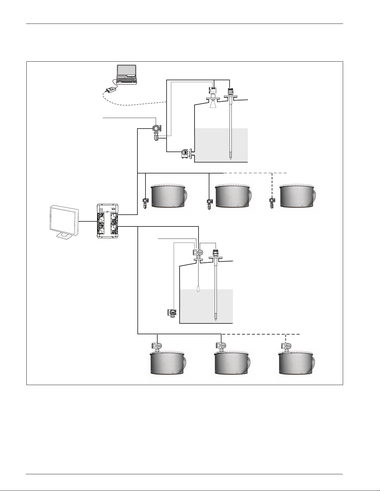
1.4 System functional diagram
Figure 1-1: Connection with 7500 Series Radar Tank Gauge and 6000 Series Servo Tank
Gauge
2 Installation and Operations Manual
Page 13

4532 Safety instructions
2 Safety instructions
2.1 Installation, commissioning and operation
• Mounting, electrical installation, start-up and maintenance of the instrument may
only be carried out by trained personnel authorized by the operator of the facility.
• Personnel must absolutely and without fail read and understand this manual before
carrying out its instructions.
• The instrument may only be operated by personnel who are authorized and trained
by the operator of the facility. All instructions in this manual are to be observed
without fail.
• The installer must make sure that the measuring system is correctly wired
according to the wiring diagrams. The measuring system is to be grounded.
• Please observe all provisions valid for your country and pertaining to the opening
and repairing of electrical devices.
2.2 Product Requirements
2.2.1 Power source
Check the voltage of the power supply before connecting it to the product. It should be
the exact voltage required for proper operation of the product.
2.2.2 Use in hazardous areas
When using the product in the first or second-class hazard location (Zone 1 or Zone 2)
be sure to use an intrinsically safe or pressure and explosion-proof apparatus. Take the
utmost care during the installation, wiring, and piping of such apparatus to ensure the
safety of the system. For safety reasons, maintenance or repairs on the product while it
is being used with such apparatus should only be performed by qualified personnel.
2.2.3 External connection
When an external connection is required, the product should be protectively grounded
before it is connected to a measurement object or an external control circuit.
2.3 Operational safety
2.3.1 Hazardous area
Measuring systems for use in hazardous environments are accompanied by separate "Ex
documentation", which is an
installation instructions and ratings as stated in this supplementary documentation is
mandatory.
integral part
of this manual. Strict compliance with the
• Please use the explosion-proof type for measurement in explosion-hazardous
areas.
• Instruments used in explosion hazardous areas should be mounted and wired
according to the explosion-proof regulations.
Varec, Inc. 3
Page 14

Safety instructions Average Temperature/Water Bottom Sensor and Converter
• Instruments mounted in explosion hazardous areas must not be opened when the
power is on. Tighten the cable gland firmly.
• The maintenance and repair of the instrument is limited to fulfill the explosion
proof regulations.
• Ensure that all personnel are suitably qualified.
• Observe the specifications in the certificate as well as national and local regulations.
2.3.2 Power supply
Check that voltage and frequency of the local power supply are in the range of the
technical data of the instrument before turning on the power, in Chapter 12, Technical
data.
2.3.3 Grounding
Do not remove the grounding of the instrument when the power supply is turned on.
This may set the instrument in a dangerous condition.
2.3.4 Wiring
2.4 Return
Make sure of the grounding of the instrument before connecting input and output to
another system.
Caution! Changes or modifications not expressly approved by the party responsible for com-
pliance could void the user’s authority to operate the equipment.
The following procedures must be carried out before the instruments is sent to Varec
for repair:
• Always enclose a duly completed "Declaration of Contamination" form. Only then
can Varec transport, examine and repair a returned device.
• Enclose special handling instructions if necessary, for example, safety data sheet as
per EN 91/155/EEC.
• Remove all residue which may be present. Pay special attention to the gasket
grooves and crevices where fluid may be present. This is especially important if the
fluid is dangerous to health, e.g. corrosive, poisonous, carcinogenic, radioactive,
etc.
A copy of the “Declaration of Contamination” is included at the end of this operating
manual in Appendix B.
Caution! No instrument should be sent back for repair without all dangerous material being
completely removed first, e.g. in scratches or diffused through plastic.
• Incomplete cleaning of the instrument may result in waste disposal or cause harm
to personnel (burns, etc.). Any costs arising from this will be charged to the
operator of the instrument.
2.5 Disposal
In case of disposal, please separate the different components according to their material
consistency.
4 Installation and Operations Manual
Page 15

4532 Safety instructions
EX
EX
2.6 Notes on safety conventions and symbols
In order to highlight safety-relevant or alternative operating procedures in the manual,
the following conventions have been used, each indicated by a corresponding symbol in
the margin.
Safety conventions
Warning!
Caution!
Note!
Explosion protection
Warning!
A warning highlights actions or procedures which, if not performed
correctly, will lead to personal injury, a safety hazard or destruction of
the instrument
Caution!
Caution highlights actions or procedures which, if not performed
correctly, may lead to personal injury or incorrect functioning of the
instrument
Note!
A note highlights actions or procedures which, if not performed
correctly, may indirectly affect operation or may lead to an instrument
response which is not planned
Device certified for use in explosion hazardous area
If the device has this symbol embossed on its name plate, it can be
installed in an explosion hazardous area
Explosion hazardous areas
Symbol used in drawings to indicate explosion hazardous areas.
• Devices located in and wiring entering areas with the designation
“explosion hazardous areas” must conform to the stated type of
protection
Safe area (non-explosion hazardous area)
Symbol used in drawings to indicate, if necessary, non-explosion
hazardous areas.
• Devices located in safe areas still require a certificate if their
outputs run into explosion hazardous areas
Explosion protection
Direct voltage
A terminal to which or from which a direct current or voltage may be
applied or supplied
Alternating voltage
A terminal to which or from which an alternating (sine-wave) current or
voltage may be applied or supplied
Grounded terminal
A grounded terminal, which as far as the operator is concerned, is
already grounded by means of an earth grounding system
Protective grounding (earth) terminal
A terminal which must be connected to earth ground prior to making
any other connection to the equipment
Equipotential connection (earth bonding)
A connection made to the plant grounding system which may be of type
e.g. neutral star or equipotential line according to national or company
practice
Varec, Inc. 5
Page 16

Safety instructions Average Temperature/Water Bottom Sensor and Converter
6 Installation and Operations Manual
Page 17
4532 Identification
3 Identification
3.1 Device designation
3.1.1 Nameplate
4532 Series
Temperature Device
Ex ia IIB T
ATEX II 1/2 G
KEMA 08 ATEX 0012 X
Ambient Temperature -40 °C to °C
Ui<30V Ii<120mA Pi<1W
Ci=7.9nF Li=48µH
Do not modify parts and circuits of this instrument.
5834 Peachtree Corners East Norcross (Atlanta)
Made in Japan
WARNING
Varec, Inc.
Georgia 30092 USA
16-04532AT Rev B
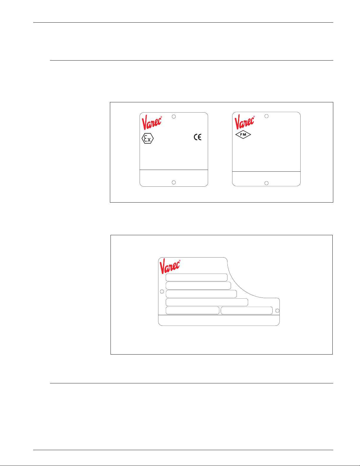
Figure 3-1: 4532 ATC labels
N453
Order Code
Mfg. Date
Serial No.
Span °C to °C
0820
APPROVED
Ambient Temperature -40 °C to °C
Ui<30V Ii<120mA Pi<1W
Ci=6.6nF Li=48μH
Do not modify parts and circuits of this instrument.
5834 Peachtree Corners East Norcross (Atlanta)
Made in Japan
453x Series
Temperature Device
Length mm
5834 Peachtree Corners East Norcross (Atlanta)
Varec, Inc.
Georgia 30092 USA
4532 Series
Temperature Device
IS Cl. I, Div. 1, Gp. C,D
Cl. I, Zone0, AEx ia IIBT
NI Cl. I, Div. 2, Gp. C,D
WARNING
Install per control drawing Ex461-869
Varec, Inc.
Georgia 30092 USA
16-0453x Rev EMade in Japan
16-04532 Rev C
NEMA 4X
Figure 3-2: Product label for 453x average temperature devices
3.2 Scope of delivery
• Instrument according to the version ordered
• ToF Tool (CD-ROM)
• Accessories (as ordered)
Varec, Inc. 7
Page 18

Identification Average Temperature/Water Bottom Sensor and Converter
3.3 CE marks, declaration of conformity
The instrument is designed to meet state-of-the-art safety requirements, has been
tested and left the factory in a condition in which it is safe to operate. The instrument
complies with the applicable standards and regulations in accordance with EN 50014
"Electrical apparatus for potentially explosive atmospheres-General requirements". The
instrument described in this manual thus complies with the statutory requirements of
the EG directives. Varec confirms the successful testing of the instrument by affixing to
it the CE mark.
8 Installation and Operations Manual
Page 19
4532 Installation
4 Installation
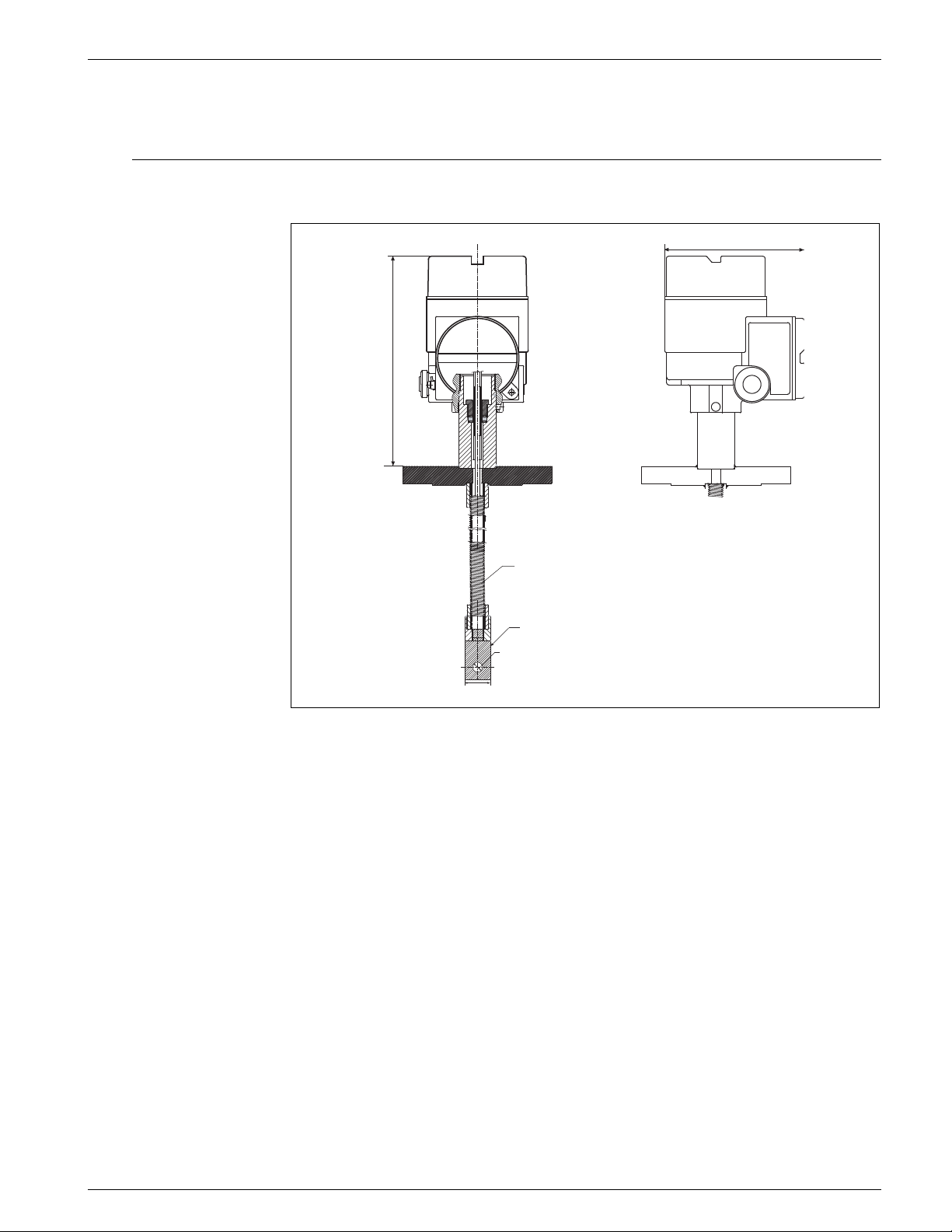
4.1 Design, dimensions
142.5 mm
215 mm
Ф10
Ф26
Figure 4-1: 4532 ATC dimensions
Flexible tube
depends on the
tank height
Bottom hook
Varec, Inc. 9
Page 20
Installation Average Temperature/Water Bottom Sensor and Converter
Recommended procedure
Incorrect procedure
4.2 Unpacking
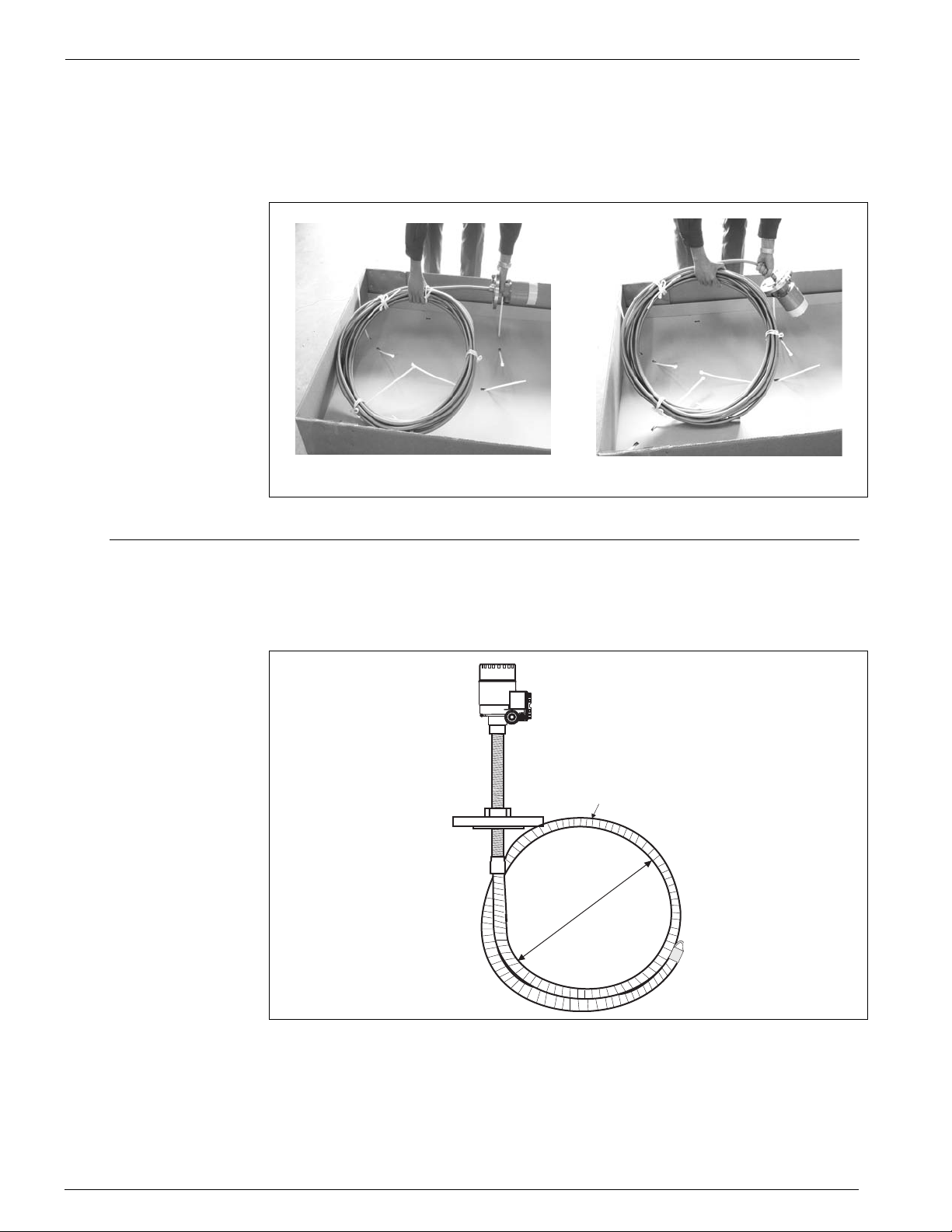
When unpacking, be careful not to bend, fold or twist the flexible tube. Please refer to
the recommended procedure below.
4.3 Flexible tube
When attaching and bending the flexible tube, the radius of curvature must be at least
300 mm (11.8") at any bend portion.
Flexible tube
Min.1m (39.37")
Figure 4-2: Flexible tube
Note! If a flexible tube is bent with a radius of curvature less than 300 mm (11.8"), the flex-
ible tube or the measuring element may be seriously damaged or broken.
10 Installation and Operations Manual
Page 21

4532 Installation
4.4 Installation Instructions
Note! The level sensor circuit is connected to ground and is infallibly galvanically isolated
from the supply and output circuit and from the temperature measurement circuit.
All metal parts of the sensor and the transmitter shall be electrically conductive and
securely be connected to the potential equalization system within the hazardous area.
4.5 Special conditions for safe use
To exclude ignition sources due to sparks caused by impact or friction, even in the event
of rare incidents, do not subject the temperature sensor tube to environmental stress,
such as impact from moving parts. Also, make sure the bottom part is secured.
Varec, Inc. 11
Page 22

Installation Average Temperature/Water Bottom Sensor and Converter
12 Installation and Operations Manual
Page 23
4532 Mounting
5 Mounting
5.1 Mounting instruction
Note!
1. The flexible tube length of the 4532 ATC is defined for the customer’s specifications. Before mounting, please check as follows:
• The tag number (if available) on the body of the 4532 ATC
• The length of the flexible tube
• The number of measuring points
• The intervals between measuring point
2. Mounting the 4532 ATC at a minimum of 500 mm (19.67") away from the tank shell.
This will ensure that the measurement is not influenced by changes in ambient
temperature.
3. The procedure for mounting the 4532 ATC on a tank depends on the type of tank.
Here we shall explain the procedures for a fixed roof tank and for a floating roof
tank.
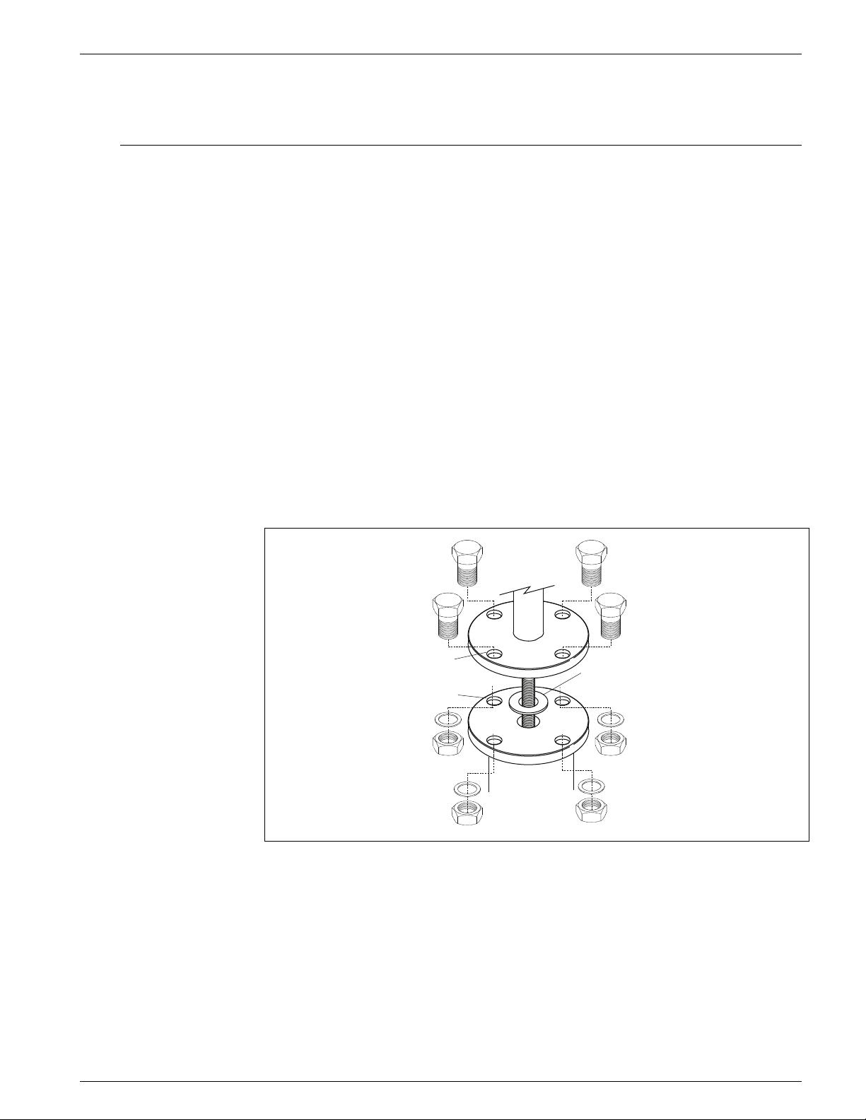
In any case, the flexible tube head is mounted on the tank top as show in fig. 5.
The mounting nozzle should have a diameter of 50 mm (2") as standard.
Bolt M16
Flange for
flexible tube head
Flange for
tank top
Washer M16
Nut M16
Packing
Figure 5-1: The 4532 ATC mounting
Varec, Inc. 13
Page 24
Mounting Average Temperature/Water Bottom Sensor and Converter
5.2 Mounting on a fixed roof tank
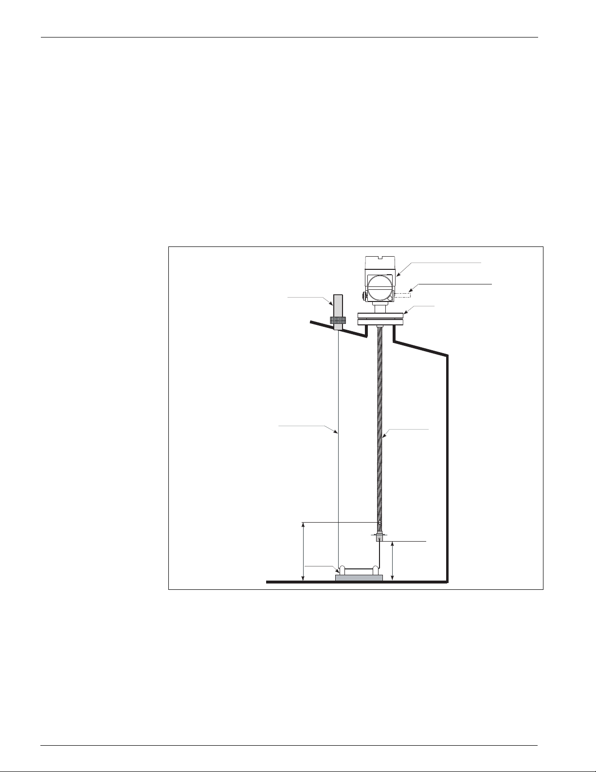
There are three methods for mounting the 4532 ATC on a fixed roof tank:
• Top anchor method
• Thermo well method
• Anchor weight method
If the tank bottom has a heating coil, the clearance from the flexible tube bottom hook
to the tank bottom may increase depending on the heating coil type.
5.2.1 Top anchor method
The flexible tube is stabilized by a wire hook and a top anchor.
Electrical compartment
Cable entry as specified
Top anchor
Flange
Socket (1")
Tensioning wire
From tank botto m to
element position #1
approx.500 mm
Tank bottom
(20")
Figure 5-2: Top anchor application
Flexible tube
Ø26 mm(1.02")
Clearance below
bottom hook
400 mm (15.57")Wire hook
1. Insert a gasket and lower the flexible tube from the nozzle on the tank top.
Caution! The flexible tube must be lowered carefully without bending too much and scratching
at the inner edge of the nozzle hole.
2. Rotate the 4532 ATC so that you can set up the cabling in the most convenient way.
3. Straighten the tensioning wire, fix the wire end to the top anchor temporarily and
lower the wire.
14 Installation and Operations Manual
Page 25
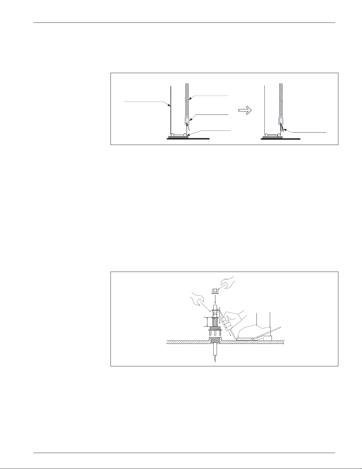
4532 Mounting
Flexible tube
Wire hook
Provided wire
Tensioning wire
Bottom hook
4. Draw the tensioning wire through the wire hook on the tank bottom.
5. Wrap the tensioning wire twice around the hole on the bottom hook, tighten it and
wrap the provided wire around it (see Figure 5-3).
Figure 5-3: Tensioning wire mounting
6. Fix the mounting flange of the 4532 ATC to the nozzle on the tank top using bolts.
Note! Please keep the compression of the spring at 35 to 37 mm (1.38 to 1.47).
If you compress the spring over 35 to 37 mm, it may cause damage to the sensor.
7. Draw the end of the tensioning wire as much as possible by hand and foot (see
Figure 5-4)
8. Bend the wire and fix it using the nut.
9. Cut the excess wire.
10. Screw the nut to compress down the spring of the top anchor 35 to 37 mm.
11. Cover the top anchor.
35~37mm
Figure 5-4: Top anchor mounting
Varec, Inc. 15
Page 26
Mounting Average Temperature/Water Bottom Sensor and Converter
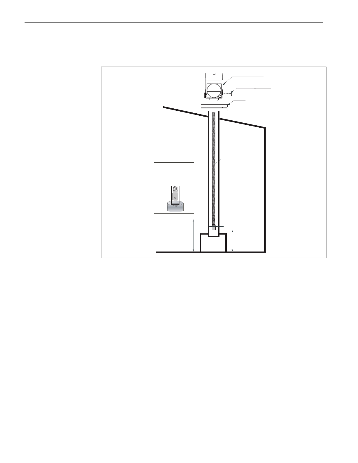
5.2.2 Thermo well method
The flexible tube is inserted into a thermo well with a diameter of 2" or more.
Electrical compartment
Cable entry as specified
Flange
Flexible tu b e
If the tank internal
pressure exceeds
1bar, fix the thermo
well in accordance
with below figure.
welding
From tank botto m to
element position #1
approx.500 mm
Tank bottom
(20")
Ø26 mm(1 .02")
Clearance below
bottom hook
400 mm (15.57")
Figure 5-5: Thermo well application
Caution! The flexible tube must be lowered carefully without bending too much or scratching
at the inner edge of the nozzle hole.
1. Insert a gasket and lower the flexible tube into the inlet of the stilling well.
2. Rotate the 4532 ATC so that you can set up the cable in the most convenient way.
3. Fix the mounting flange of the 4532 ATC to the nozzle on the tank top using bolts.
16 Installation and Operations Manual
Page 27
4532 Mounting
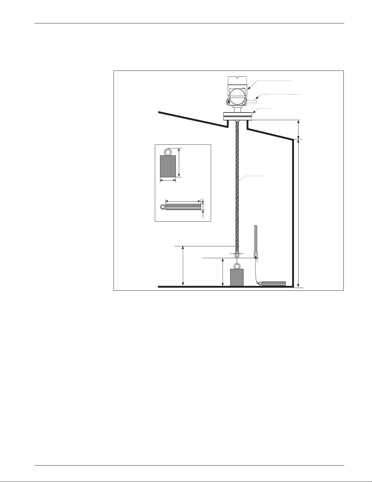
t
5.2.3 Anchor weight method
The flexible tube is stabilized by an anchor weight:
Elec trical comp a rtm ent
Cable entry as specified
Flange
Nozzle heigh
222 mm(8.74")
Flexible tube
Ø120 mm(4.72" )
1000mm(39.37")
From tank bo tto m to
element position #1
approx.500 mm
(20")
41mm(1.61")
Clearance below
bottom hook
400 mm (15.57")
Tank bottom
Ø26 mm(1.02")
Tank height
Figure 5-6: Anchor weight application
Note! Make sure to put the anchor weight on the tank bottom. When installing with the sus-
pended anchor weight, please use the anchor weight at a maximum of 16 kg. More
weight may cause internal breaking in the flexible tube.
Caution! The flexible tube must be lowered carefully without bending too much and scratching
at the inner edge of the nozzle hole.
1. Insert a gasket and lower the flexible tube from the nozzle on the tank top.
2. Rotate the 4532 ATC so that you can set up the cabling in the most convenient way.
3. Tighten the tensioning wire between the lower end of the flexible tube and the
anchor weight.
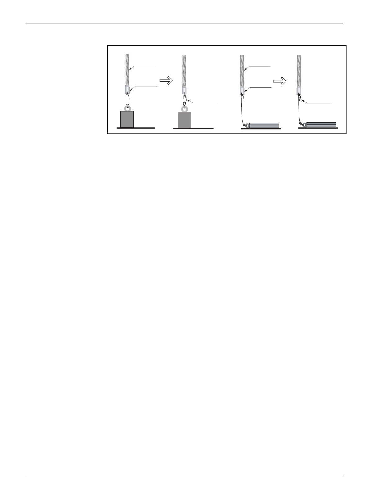
4. Wrap the tensioning wire twice around a hole on the bottom hook, tighten it and
wrap a provided wire around it (see Figure 5-7 on page 16).
5. Fix the mounting flange of the 4532 ATC to the nozzle on the tank top using bolts.
Varec, Inc. 17
Page 28
Mounting Average Temperature/Water Bottom Sensor and Converter
Flexible tube
Provided wire
Bottom hook
Flexible tube
Provided wire
Bottom hook
Figure 5-7: Anchor weight mounting
18 Installation and Operations Manual
Page 29
4532 Mounting
5.3 Mounting on a floating roof tank
There are three methods of mounting the 4532 ATC on a floating roof tank:
• Top anchor method
• Thermo well method
• Guide wire ring method
Note! If the tank bottom has a heating coil, the clearance from the flexible tube or probe
bottom hook to the tank bottom must increase according to the heating coil type.
5.3.1 Top anchor method
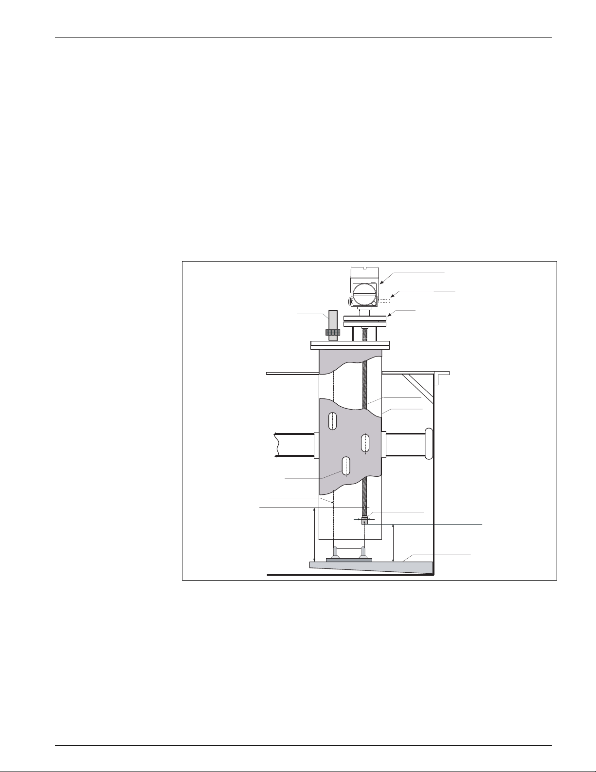
The flexible tube is installed in a fixed pipe and stabilized by a top anchor. The 6000
Series Servo Tank Gauge and 4532 ATC can be mounted in the same fixed pipe.
Electrical compartment
Cable entry as specified
Top anchor
Gas hole
Tensioning wire
Element position #1
(Bottom element)
500mm (19.69")
Flange
Flexible tube
Fixed pipe
Ø26mm (1.02")
400mm (15.75)
Clearance below
bottom hook
Gauge plate
Figure 5-8: Top anchor application
The installation procedure is the same as for mounting on a fixed roof tank using the
top anchor.
Varec, Inc. 19
Page 30
Mounting Average Temperature/Water Bottom Sensor and Converter
5.3.2 Thermo well method
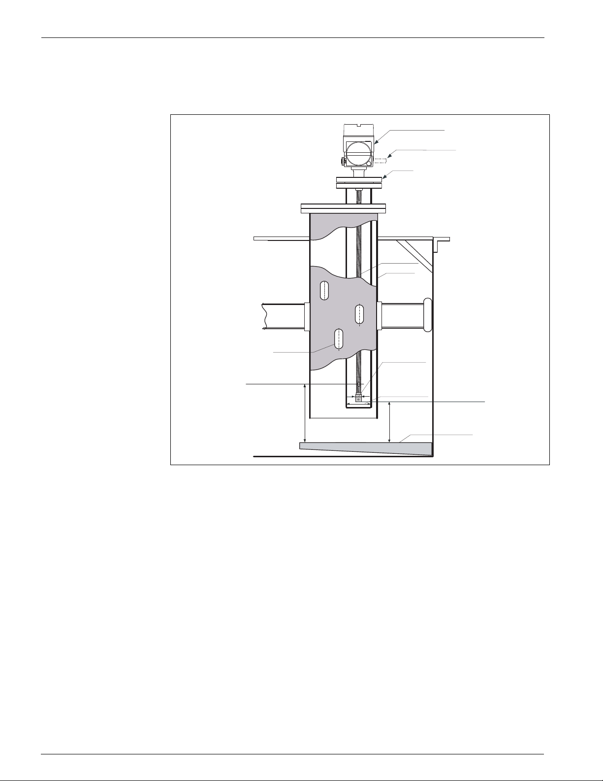
The flexible tube is inserted into a thermo well in the fixed pipe.
Electrical compartment
Cable entry as specified
Flange
Flexible tube
Fixed pipe
Gas hole
Ø26mm (1.02")
Element position #1
(Bottom element)
500mm (19.69")
Thermo well
(Min.Ø2",
depend on sch. )
400mm (15.75)
Clearance below
bottom hook
Gauge plate
Figure 5-9: Thermo well application
The installation procedure is the same as for mounting on a fixed roof tank using the
thermo well.
20 Installation and Operations Manual
Page 31
4532 Mounting
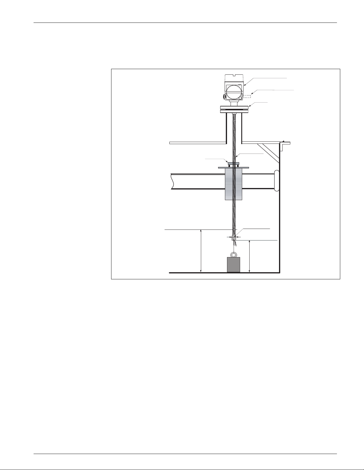
5.3.3 Guide ring and anchor weight method
The flexible tube is stabilized by a guide ring and anchor weight.
Electrical compartment
Cable entry as specified
Flange
Guide ring
Element position #1
(Bottom element)
500mm (20")
Tank bottom
Flexible tube
Ø26mm (1.02")
Clearance below
bottom hook
400mm (15.75)
Figure 5-10:Guide ring and anchor weight application
Caution! Make sure to put the anchor weight on the tank bottom. When installing with the sus-
pended anchor weight, please use the anchor weight at a maximum of 16kg. More
weight may cause internal breaking in the flexible tube.
Caution! The flexible tube must be lowered carefully without bending too much and scratching
at the inner edge of the nozzle hole.
1. Set the guide ring to the floating roof.
2. Insert a gasket and lower the flexible tube from the nozzle on the tank top.
3. Rotate the 4532 ATC so that you can set up the cabling in the most convenient way.
4. Tighten the tensioning wire between the lower end of the flexible tube and the
anchor weight. Wind the tensioning wire twice around each of the hitches and wrap
a wire around it (see Figure 5-7 on page 16).
5. Fix the mounting flange of the 4532 ATC to the nozzle on the tank top using bolts.
Varec, Inc. 21
Page 32

Mounting Average Temperature/Water Bottom Sensor and Converter
22 Installation and Operations Manual
Page 33
4532 Wiring
Z1
H2-
H2+
H1-
H1+
Z2
Z3
AR1
H2-
H2+
H1-
H1+
6 Wiring
6.1 Terminal Connection
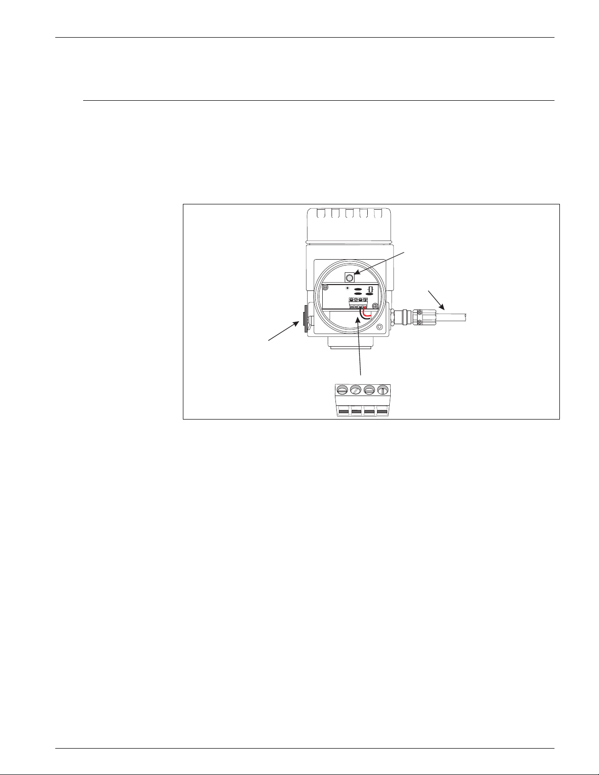
6.1.1 4532 ATC terminal
Note! The 4532 ATC allows an intrinsically safe HART connection only . Please refer to the
i.s. regulation for establishing wiring and field device layout.
Ground terminal
Screened twisted pair
or steel armored wire
Note!
Metal cable gland only:
Shield of HART communication
line must be grounded
H1+
Temp. data
I.S. HART on 4532 ATC
+ : H1 + terminal
- : H1 - terminal
to 4590 TSM
+ terminal 24, 26 or 28
- terminal 25, 27 or 29
or
to 6000 STG
+ teminal 24
- terminal 25
Zincate-plate
aluminum plug
Multi-drop HART loop
Daisy chain connection
+ : H2 + terminal
- : H2 - terminal
H2-
Z1
AR1
Z2
Z3
H2-
H2+
H1-
H1+
H2+
H1-
Figure 6-1: 4532 ATC terminal
The 4532 ATC has convenient daisy chain HART loop terminals that enable the 4532
ATC to be a terminal junction for HART multi-drop instruments.
Varec, Inc. 23
Page 34
Wiring Average Temperature/Water Bottom Sensor and Converter
4 ... 20 mA
4 ... 20 mA
Channel 1
Channel 2
Port_A+
Port_A-
IS HART
or
+
+
_
_
A
B
b
22
23
24
25
26
+
_
COM
HOIST
STOP
Operation
contact
input
20
21
16
19
18
17
Alarm contact
Alarm contact
Alarm contact
+
_
+
_
+
_
10
15
14
13
12
11
Alarm contact
+
_
Port_B-
Port_B+
Non IS HART
to NRF or others
+
_
9
8
7
6
5
4
Power supply
AC 85 ... 264V 50/60Hz
or
DC 20 ... 62V AC20 ... 55V
2
3
1
G
N
L
L
G
N
ARS
ARS
ARS
+
_
Digital output
Rack bus RS485,
Serial pulse,
or
HART
From 4535 ATC
R
R
R
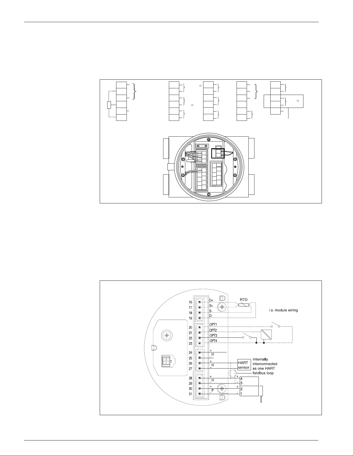
6.1.2 6000 Series Servo Tank Gauge terminal
Since the 4532 ATC is an intrinsically safe instrument, the terminal connection to the
Ex i side on HART connection is allowed on the 6000 Series Servo Tank Gauge terminal
housing.
Figure 6-2: 6000 Series Servo Tank Gauge terminal
Note! Do not connect the 4532 ATC HART communication on terminals 4 and 5 on the
6000 Series Servo Tank Gauge. These terminals are designed to connect Ex d
HART communication.
6.1.3 4590 TSM i.s. terminal
4590 TSM i.s. terminal board
1
2
3
NRF
46
RC
8
10
12
b
B
25
P_A-
A
24 26
P_A+
23
22
OT2-
OT2+
21
OT1-
20
OT1+
19
N.C.
18
CTR2
17
CTR1
COM
AL4
15
14 16
AL4
ARS
L
L
G
ARS
N
GND
N
ARS
NRF-
5
+
A/+
RC
B/-
7
AL1
AL1
9
AL2
AL2
11
AL3
AL3
13
mA
24V
Figure 6-3: 4590 TSM terminal
For 7500 Series
Radar T ank Gauges only!
24 Installation and Operations Manual
Page 35
4532 Wiring
Z1
H2-
H2+
H1-
H1+
Z2
Z3
AR1
Note! The 4590 TSM has three sets of i.s. HART terminals. These three pairs are looped
internally.
Caution! Do not connect signal HART lines from the 4532 ATC to terminals 30 and 31. They
are designed to supply drive power for the 7500 Series Radar Tank Gauge only.
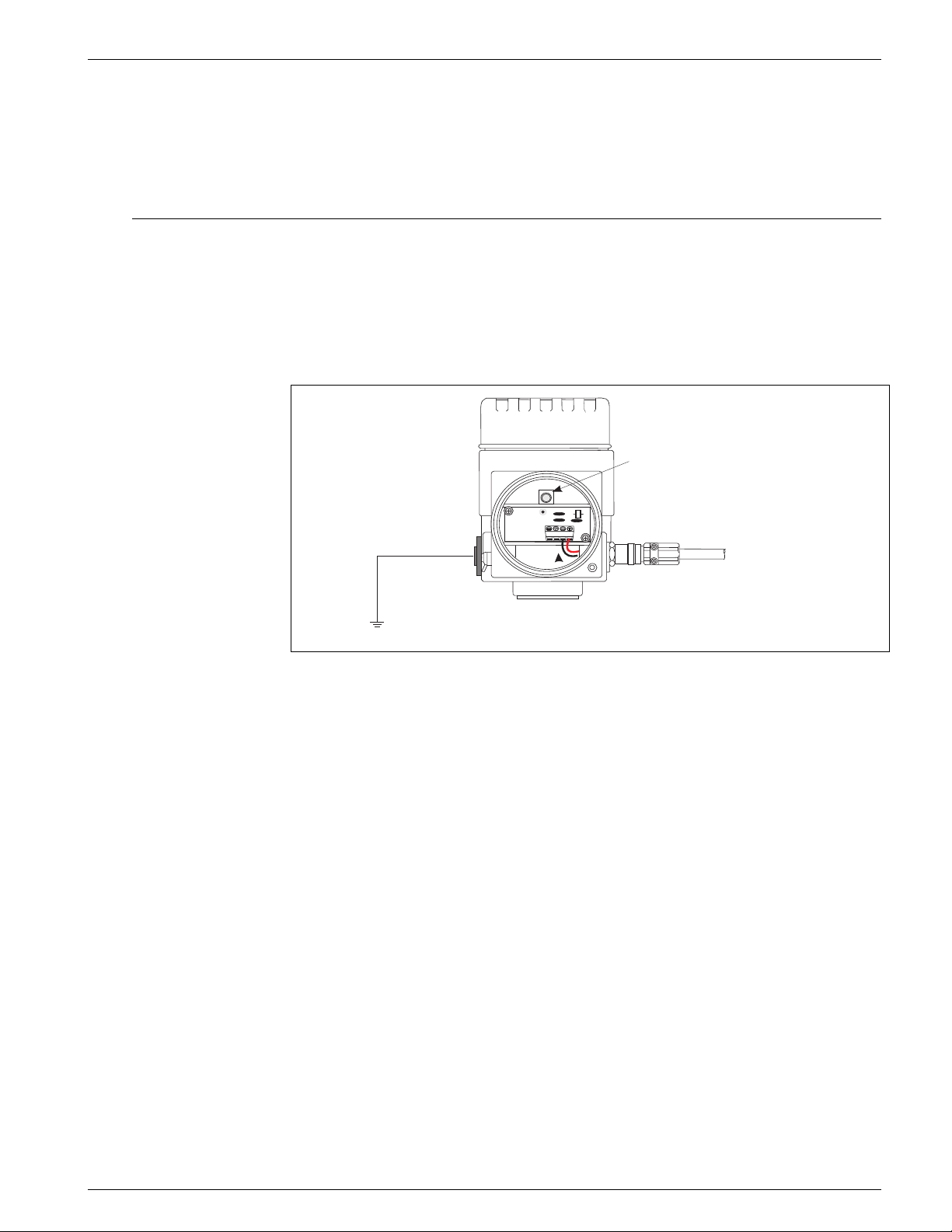
6.2 Grounding
The 4532 ATC must be grounded to the tank potential before communication and power
connections are made. The connections from ground terminal of the 4532 ATC to the
tank ground must be made before any other wiring connections are made. All grounding
must be compliant with local and company regulations and checked before the
equipment is commissioned.
Ground terminal
A > 4 mm
2
Tank Ground
Figure 6-4: The 4532 ATC Grounding
Z1
AR1
Z2
Z3
H2-
H2+
H1-
H1+
to 4590 TSM or
6000 Series Servo
Tank Gauge
Varec, Inc. 25
Page 36

Wiring Average Temperature/Water Bottom Sensor and Converter
26 Installation and Operations Manual
Page 37

4532 Operating
7 Operating
7.1 Local HART connection
7.1.1 As a Varec tank gauging instrument
The 4532 ATC has been developed and designated primarily to work with the Varec tank
gauging host instruments 4590 TSM or 6000 Series Servo Tank Gauge.
Temperature information is transmitted on a two wire i.s HART loop to the host
instrument.
Since both the 4590 TSM and 6000 Series Servo Tank Gauge have a pre-configured
menu for 453x average temperature devices functionality as default, simple wiring to
the 4532 ATC will complete the initial setup for the 4532 ATC.
7.1.2 As a standalone generic HART instrument
The 4532 ATC is a HART foundation registered intrinsically safe loop powered device.
The 4532 ATC provides four basic types of data as standard and parameter information
via HART protocol, command 3. Configuration to host communication can be performed
by a HC (Hand Communicator) or the Varec ToF field service tool to set a specific HART
address.
20: Measurement function
• 0: Converter only
• 1: Temperature + converter
These four basic data are available as standard.
• Average liquid temperature
• Average gas phase temperature
• Level (entered liquid level at "VH02 measured distance")
• Device status
7.2 Device set up: 4590 TSM
Connect the loop powered HART communication cable from the 4590 TSM (intrinsically
safe side compartment) to the 4532 ATC.
Since the 4590 TSM has been designed to recognize the 4532 ATC as a specific Varec
HART instrument, set up is easy.
7.2.1 HART scanner
After the physical cabling between the 4532 ATC and the 4590 TSM is complete, scan
all connected loop powered HART devices by activating "HART SCAN" on the version 1.x
4590 TSM. The version 2.x 4590 TSM continually scans the HART bus and will
automatically detect the 4532 ATC when it is connected.
Caution! Not all 4590 TSM have fully accessible compatibility to recognize the 4532 ATC.
Consult with your Varec representative to cross check the software and hardware
version of the 4590 TSM.
Varec, Inc. 27
Page 38

Operating Average Temperature/Water Bottom Sensor and Converter
7.2.2 The 4532 ATC specific parameter set up on the 4590 TSM
Configuration of 4532 ATC parameters on the display of the 4590 TSM is dependent on
the installed software and hardware version of the 4590 TSM. Please refer to the
operating manual for the 4590 TSM to determine accessible parameters.
All required initial setup and configuration can be performed by the ToF field service
tool. Detailed information will be described in the following operation related chapters.
7.3 Device set up: 6000 Series Servo Tank Gauge
The 6000 Series Servo Tank Gauge is also specifically designed to recognize the 4532
ATC. Connect local HART cabling between the 4532 ATC and the 6000 Series Servo Tank
Gauge on terminals 24 and 25.
7.3.1 Preparation of 6000 Series Servo Tank Gauge
The 6000 Series Servo Tank Gauge must be pre-configured to accept the 4532 ATC
connection via the multi drop HART loop.
GVH362: NMT connection
"Average Temp." must be selected in order to configure the 4532 ATC.
Caution! To change this parameter, an access code is required. Please refer to the 6000
Series Servo Tank Gauge operation manual for further information.
7.3.2 4532 ATC configuration on 6000 Series Servo Tank Gauge
Most required 4532 ATC parameters can be configured on G4 "Temperature" matrix as
it is on the display of the 6000 Series Servo Tank Gauge.
Typical 4532 ATC parameters (equivalent to the 4535 ATC) are displayed on the matrix
of the 6000 Series Servo Tank Gauge.
7.3.2.1 G0 Static matrix
GVH010: Liquid Temp
Calculated average liquid temperature value, determined by the 4532 ATC
GVH013: Gas Temperature
Calculated average gas phase temperature value, determined by the 4532 ATC
GVH440: Liquid Temp
The same value indicated on GVH010 Liquid Temp
GVH441: Gas Temperature
The same value indicated on GVH013 Gas Temperature
GVH442: Measured Level
Liquid level value established in the 6000 Series Servo Tank Gauge. The 4532 ATC must
have liquid level data in order to calculate both liquid and gas phase average
temperature.
28 Installation and Operations Manual
Page 39

4532 Operating
GVH447: Reference Zero
Indication of the converted 100 Ohm reference resistor deviation value compared to the
actual inserted element value in the temperature probe. The reading value of reference
resistor and its deviation are continuously monitored during operation to prevent from
performing an incorrect calculation. Indicated tolerance should be within ±0.15°C
(±0.27°F) depending on element characteristics, e.g. Pt100 elements have 100 Ohm
resistance at 0°C (32°F); therefore, the reading value should be within 0°C±0.15°C
(32°F±0.27°F) or less.
GVH449: Reference 150
Indication of the converted 200 Ohm reference resistor deviation value compared to the
actual inserted element value in the temperature probe. The reading value of reference
resistor and its deviation are continuously monitored during operation to prevent from
performing an incorrect calculation. Indicated tolerance should be within ±0.15°C
(±0.27°F) depending on element characteristics.
GVH450~459; Temp No.1~10
The temperature reading value from each inserted element in the probe. The reading
element temperature above 11~16 must be selected at the GVH470 "Select Point", then
the read value at the GVH473 "Element Temp."
GVH460~49; Element Position No.11~16 (not available with 4532 ATC)
GVH470: Select Point
A matrix to select the desired element data on GVH471 "Zero Adjust", GVH473 "Element
Temp" and GVH474 "Element Position."
GVH480: Diagnostic
Display of error code message. Please refer to the error code chart in
Chapter 9, Maintenance.
GVH482: Total No. Element
Enter the number of installed temperature elements in the average temperature probe.
GVH485: Type of Interval
Select type of element interval.
Even: Element spacing will be equally spaced by providing the distance at GVH487
"Element Interval", and the lowest element position can be set at GVH486 "Bottom Point."
GVH486: Bottom Point
The lowest inserted element position in the average temperature probe.
Note! This parameter setting is only used to change the theoretical element position within
the 4532 ATC's software for average calculation purposes. If does not effect the
physical location of the temperature element position.
Varec, Inc. 29
Page 40

Operating Average Temperature/Water Bottom Sensor and Converter
30 Installation and Operations Manual
Page 41

4532 Operation and Description of Instrument Function
8 Operation and Description of Instrument Function
8.0.1 HART Device designation
HART device code "190":
Device code for temperature measurement function in 4532 ATC only.
8.0.2 Device Data
Tag Number: read and write
Default: HART
A customer specific device identification and control number (or name). Tank name, site
number, or any other ID can be entered.
Assembly Number: read and write
Default: 0
Manufacture control number based on production process.
8.1 Temperature measurement
8.1.1 Primary values: VH00 ~ VH09
VH00 Liquid Temp
Item type: read only
Range: -200°C ~ 240°C
Note! Display of measured liquid phase average temperature. Liquid level input must be
provided by the 7200 or 7500 Series Radar Tank Gauge (via 4590 TSM) or 6000
Series Servo Tank Gauge in order to calculate true liquid average temperature.
VH01 Gas Temp
Item type: read only
Range: -200°C ~ 240°C
Display of measured gas (vapor) phase average temperature.
Note! Display of measured gas (vapor) phase average temperature. Liq uid level input
must be provided by the 7200 or 7500 Series Radar Tank Gauge (via 4590 TSM) or
6000 Series Servo Tank Gauge in order to calculate true gas average temperature.
VH02 Measured Distance
Item type: read and write
Range: 0mm ~ 99999mm
Display of provided liquid level by connected level gauge. Manual level input is also
available for the purpose of device testing.
Varec, Inc. 31
Page 42

Operation and Description of Instrument Function Average Temperature/Water Bottom Sensor and Converter
VH07 Temperature 0
Item type: read only
Display of converted 100 Ohm reference resistor deviation value compared to actual
inserted element value in temperature probe. The reading value of reference resistor
and its deviation are continuously monitored during operation to prevent an incorrect
calculation.
VH09 Temperature 17
Item type: read only
Display of the converted 200 Ohm reference resistor deviation value compares to the
actual inserted element value in the temperature probe. The reading value of the
reference resistor and its deviation are continuously monitored during operation to
prevent an incorrect calculation. Indicated tolerance should be within ±0.15°C (±0.27°F)
depending on element characteristics.
8.1.2 Element Temperature 1: VH10 ~ VH15
(VH16~19 used only in 4539 ATC539)
VH10 ~ 19 Temperature 1 ~ 10
Item type: read only
Range: -200°C ~ 240°C
Display of individual measured element temperature.
8.1.3 Element Temperature 2: VH20 ~ VH29
( not available in 4532 ATC)
VH26 Selec. Ave Method
Item type: select
Selection: Standard, Advanced
Selection of average calculation method.
Standard
A Conventional calculation method. Regardless of tank shape, average temperature
calculation will be performed based on the following example (example: liquid
temperature).
32 Installation and Operations Manual
Page 43
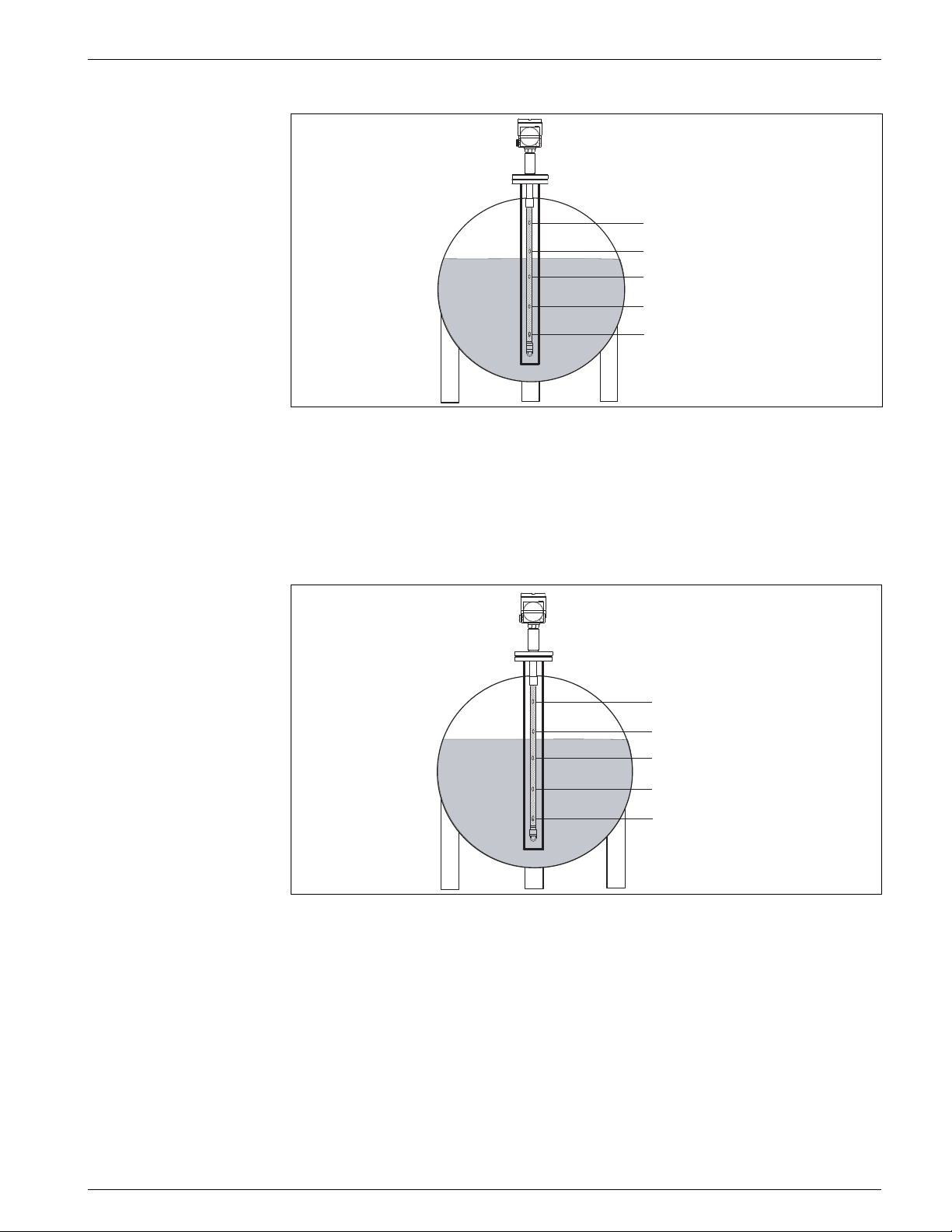
4532 Operation and Description of Instrument Function
Element #5: 4.5°C (T5)
Element #4: 4.0°C (T4)
Element #3: 2.0°C (T3)
Element #2: 3.0°C (T2)
Element #1: 3.5°C (T1)
Formula: (T1 + T2 + T3) / # of element in liquid phase
= Average temperature (3.5°C + 3.0°C + 2.0°C) / 3 = 2.83°C
Advanced:
Average temperature calculation with additional factor to compensate for unequal
volume distribution (example: liquid temperature)
Element #5: 4.5°C (T5)
Element #4: 4.0°C (T4)
Element #3: 2.0°C (T3)
Element #2: 3.0°C (T2)
Element #1: 3.5°C (T1)
Formula: (T1*V1 + T2*V2 + T3*V3) / (V1 + V2 + V3) = Average temperature
Note! V = # of additional volume factors and related parameters are determined at VH53,
54 and 55.
Varec, Inc. 33
Page 44
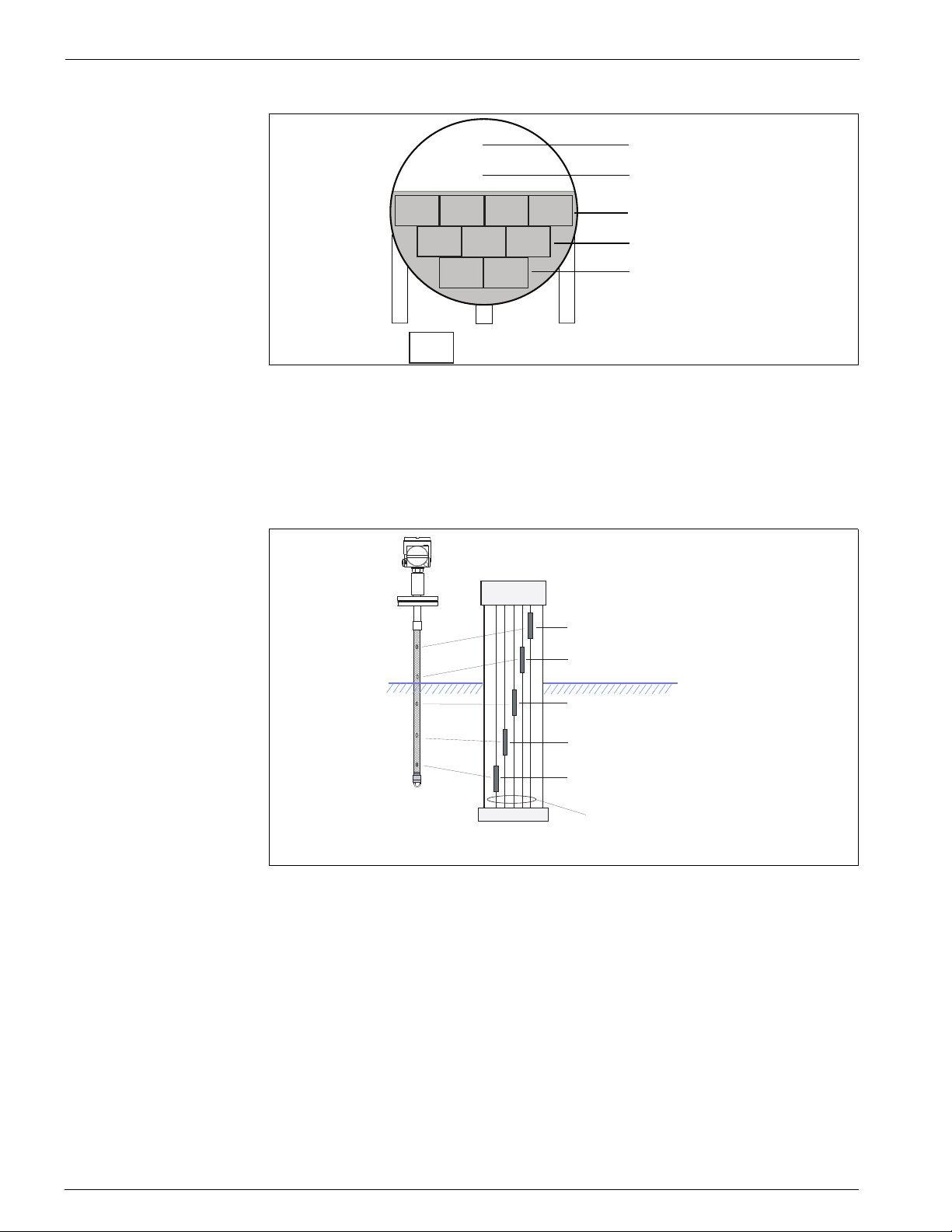
Operation and Description of Instrument Function Average Temperature/Water Bottom Sensor and Converter
Element #5: 4.5°C (T5)
Element #4: 4.0°C (T4)
2.0°C
2.0°C
2.0°C2.0°C
Element #3: 2.0°C (T3)
3.0°C
3.0°C
3.5°C
= V (volume factor)
3.0°C
3.5°C
Element #2: 3.0°C (T2)
Element #1: 3.5°C (T1)
(3.5°C x 2 + 3.0°C x 3 + 2.0°C x 4) / (2 + 3 + 4) = 2.67°C
Spot
The same number of elements (resistance and material) are located in each input cable
in the probe. Average calculation is performed based on the sum of submerged element
temperature values / total number of element submerged.
to Converter
Pt100 element #5:
24.5°C (T5)
Pt100 element #4:
24.0°C (T4)
Pt100 element #3:
26.0°C (T3)
Gas (Vapor) phase
Liquid Level
Liquid phase
Probe end
Liquid average temperature = (T1 + T2 + T3) / 3 = 25.5°C
VH28 Lower Limit
Item type: read and write
Default value: -20.5°C
RANGE: -999.9°C ~ 999.9°C
Low limit temperature alarm setpoint.
PT100 element #2:
25.5°C (T2)
Pt100 element #1:
25.0°C (T1)
input signal cable
34 Installation and Operations Manual
Page 45

4532 Operation and Description of Instrument Function
VH29 Upper Limit
Item type: read and write
Default value: 245°C
Range: -999.9°C ~ 999.9°C
Hi limit temperature alarm setpoint.
8.1.4 Element Position 1: VH30 ~ VH35 (VH36~VH39 is used only in 4539 ATC)
VH30 ~VH39 Position 1 ~ 6 (7~10 is used only in 4539 ATC)
Item type: read and write
Range: 0mm ~ 99999mm
Individual element position from tank bottom. Calculation is automatically performed
when element spacing "Even" is selected at VH85.
8.1.5 Element Position 2: VH40 ~ VH45 are not available in 4532 ATC
VH46 Hysteresis Width
Item type: read and write
Default: 10mm
Range: 0mm ~ 99999mm
Element switching point hysteresis. The hysterisis is an offset value added to the liquid
level when the level is increasing, and subtracted from the liquid level when the level is
decreasing. This setting ensures that the temperature value from an uncovered
temperature element is not used in calculating the average temperature.
VH47 Clear Memory
Item type: select
Default: None (0)
Selection: None, Clear
Reset matrix parameter to default setting.
Varec, Inc. 35
Page 46
Operation and Description of Instrument Function Average Temperature/Water Bottom Sensor and Converter
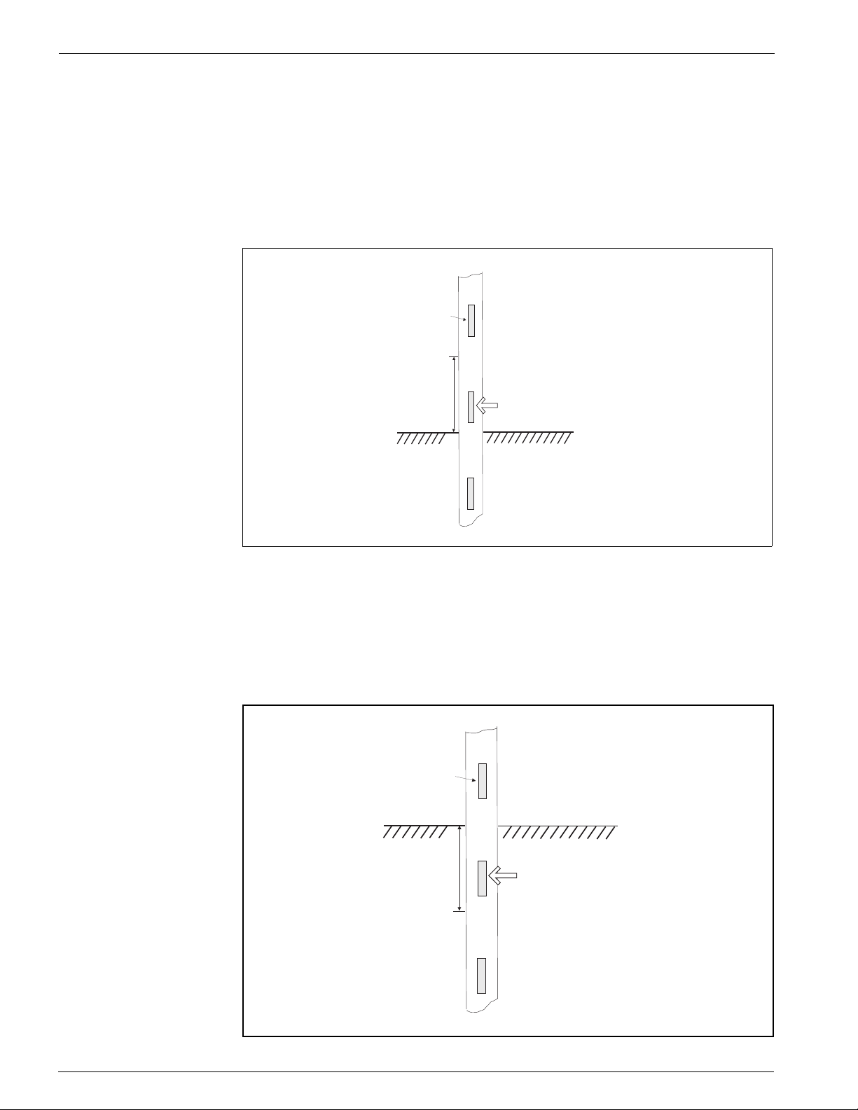
VH48 Gas Offset
Item type: read and write
Default: 300mm
Range: 0mm ~ 99999mm
A function to exclude specific element(s) from the gas (vapor) phase average
temperature calculation when the uncovered element(s) is (are) within the entered value
from the liquid level.
To 4532 ATC Electric housing
Temperature
Element
Gas phase
VH48 GAS Offset
300mm (default)
Temp. element within this range will be
excluded from Gas average calculation
Liquid Level
Liquid phase
T o Tank floor
VH49 Liquid Offset
Item type: read and write
Default: 300mm
Range: 0mm ~ 99999mm
A function to exclude element (s) from the liquid phase average temperature calculation
when the uncovered element(s) is (are) within the entered value from the liquid level.
To 4532 ATC Electric housing
Gas phase
Temperature
Element
Liquid Level
VH49 Liquid Offset:
300mm (default)
Temp. element within this range will be
excluded from liquid average calculation
Liquid phase
To Tank floor
36 Installation and Operations Manual
Page 47

4532 Operation and Description of Instrument Function
8.1.6 WB primary and Advanced temp: VH50 ~ VH59
VH53 Element Point
Item type: select
Default: 0
Selection: 0 ~ 15 (element #1 = 0, element #6 = 5)
Select element number for "Advanced" average calculation at VH26. Selected element
position will be displayed on VH54 "Element Position" and allow modification of the
volume factor at VH55 "Element Volume" for the specified element.
VH54 Element Position
Item type: read only
Range: 0m ~ 99999mm
A display of selected element position on VH53.
VH55 Element Volume
Item type: read and write
Range: 1 ~ 99999.9
For the selected element at VH53 "Element Point", extra volume can be added to the
specified element for advanced average temperature calculation. (For details, refer to
the description of VH26 "Select Average Method" on page 30)
8.1.7 WB Adjustment and Operation Power: VH60 ~ VH69
VH67 Common Voltage
Item type: read only
Range: 0 ~ 255 (0 ~ 3V)
A display of temperature element line (both signal and common) running voltage. The
detected voltage across the common line (between 0 ~ 3V) is converted to a range of
0 ~ 255 counts when it is displayed.
VH68 Output Current
Item type: read and write
Default: 16000 at 6mA
Range: 0 ~ 65536
Adjustment of 4532 ATC current consumption. In order to prevent current over-shoot
within the multidrop HART loop, this function limits the 4532 ATC power consumption
based on the set parameter. Normally, the 4532 ATC requires 6 mA or less current. Use
a tester to check the current flow in the loop. Reducing this parameter makes the
4532 ATC use less current.
Varec, Inc. 37
Page 48

Operation and Description of Instrument Function Average Temperature/Water Bottom Sensor and Converter
VH69 Ref Voltage
Item type: read and write
Default: 200
Range: 0 ~ 255
This parameter is the setpoint for the 4532 ATC power supply failure alarm. The
4532 ATC operates with a minimum 16 VDC supply voltage via the multi-drop HART
loop under normal operating conditions. The 4532 ATC transmits an error message
when the supply voltage drops below 16 VDC. The default value of 200 is equivalent to
16 VDC.
8.1.8 Temperature Adjustment: VH70 ~ VH79
VH70 Element Select
Item type: select
Range: 0 ~ 19
Allows selection of individual temperature elements for adjustment (0 = #1 element,
5 = #6 element, 19 = reference 100 Ohm resistor). Detailed values and parameters of
the selected element can be shown in:
• VH71 "Zero Adjust"
• VH73 "Temperature X"
• VH74 "Position X"
• VH75 "Resistance X"
• VH76 "Resistance Adj"
VH71 Zero Adjust
Item type: read and write
Default: 0
Range: -1000.0 ~ 1000.0
Zero adjustment of the individual element selected at VH70. This value can be adjusted
when the measured temperature of the selected element has a minor offset value as
compared to a precision reference thermometer.
For example: Selected element #2 indicates 25.4 °C. The reference thermometer
indicates 25.2 °C. Enter "-0.2" in VH71. Element #2 now has a constant offset applied to
the raw measurement.
VH72 Adjust Span
Item type: read and write
Default: 1
Range: 0.8 ~ 1.2
This span adjustment applies to all installed temperature elements. This parameter is
multiplied by the raw measurement for each individual element to calculate the
calculated temperature for each individual element.
Note! All of displayed individual temperature values are calculated based on the following
formula.
38 Installation and Operations Manual
Page 49

4532 Operation and Description of Instrument Function
VH73: "Temperature X" = raw element temperature x span (VH72) + zero offset
(VH71)
VH73 Temperature X
Item type: read only
Specified element temperature selected at VH70. The displayed value is also indicated
at individual element temperature at VH10 ~ VH25. The value is calculated based on
formula indicated on above VH72.
VH74 Position X
Item type: read and write
Range: 0mm ~ 99999mm
The position of the element specified at VH70. The position of each element is entered
when "Not Even" element spacing is selected at VH85.
VH75 Resistance X
Item type: read only
The display of the specified element resistance selected at VH70.
VH76 Resistance Adj.
Item type: read and write
Default: 0
Range: -1000.0 ~ 1000.0
Adjustment of specified element resistance at VH70. Minor resistance adjustment can
be applied on the reading value.
Note! e.g. If selected element #5 indicates 100.3 Ohm, and reference precision resistor
indicates 100.0 Ohm at the same environmental condition, then set "-0.3" in this
matrix. #5 element now has constant artificial -0.3°C offset resistance based on raw
measurement.
VH77 Element Type
Item type: select
Selection: Pt100 (must be selected in 4532 ATC)
Note! The 4532 ATC always consists of "Pt100" elements with "Spot" element layout. Do
not attempt to change these parameters.
VH78 Average Number
Item type: read and write
Default: 1
Range: 1 ~ 10
Number of samples for calculating the average temperature. Increasing this parameter
will prevent erratic changes in the calculated value.
Caution! Additional sampling # will cause slower reaction time on value switch over. Maxi-
mum 1 sampling sequence will take approximately 2 sec. {total 11 elements (6 temp
elements and 5 times for 3 reference resistors)}
Varec, Inc. 39
Page 50

Operation and Description of Instrument Function Average Temperature/Water Bottom Sensor and Converter
VH79 Protect Code
Item type: read and write
Default: 0
Range: 0 ~ 999
Access code 530 required to modify parameters.
Device setting 1: VH80 ~ VH89
40 Installation and Operations Manual
Page 51

4532 Operation and Description of Instrument Function
VH80: Present Error
Item type: read only
Display of current error message. One of the following codes will be indicated:
Error code
• 0: No error presence
• 1: Common line open
• 2: undetermined
• 3: #1 element open
• 4: #1 element short
• 5: #2 element open
• 6: #2 element short
• 7: #3 element open
• 8: #3 element short
• 9: #4 element open
• 10: #4 element short
• 11: #5 element open
• 12: #5 element short
• 13: #6 element open
• 14: #6 element short
• 23: #0 element over range
• 24: Memory defect (ROM)
• 29: Element exposed (liquid level below #1 element position)
• 30: undetermined
• 31: undetermined
• 41: Memory defect (RAM)
• 42: Memory defect (EEROM)
VH81 Temperature Unit
Item type: select
Default: °C
Selection: C, F, K
Selection of temperature display unit. Based on universal HART setting, °C(HART code:
32), °F(HART code: 33) and °K(HART code: 35) are available.
Note! Selection of temperature display unit only applies to reply data from 4532 ATC. Data
transmission from host gauge (4590 TSM or 6000 Series Servo Tank Gauge) to
4532 ATC must be performed by °C unit only (terminology of HART command 133)
Varec, Inc. 41
Page 52

Operation and Description of Instrument Function Average Temperature/Water Bottom Sensor and Converter
VH82 Element Number
Item type: read and write
Default: 2
Range: 1 ~ 6
Number of available temperature elements.
Do not change the default parameter on the 4532 ATC. The number of elements on this
version is pre-determined by the customer's choice. It may cause faulty calculation or
an inappropriate error display.
VH83 No. of Preambles
Item type: read and write
Default: 5
Range: 2 ~ 20
Number of preambles for HART communication.
VH84 Distance Unit
Item type: select
Default: mm
Selection: ft., m, inch, mm
Selection of level display unit. It applies to liquid level display on VH02 "Liquid Level".
Level units are coded based on universal HART setting, ft. (HART code: 44), m (HART
code: 45), inch (HART code: 47), mm (HART code: 49).
VH85 Kind of Interval
Item type: select
Default: Even Interval
Selection: Even Interval (always "Even" for 4532 ATC)
Selection of element interval depending on spacing layout.
Caution! Do not change this parameter on the 4539 ATC Converter + Temperature version
unless repairing. The type of Interval and individual element positions are physically
determined at factory.
VH86 Bottom Point
Item type: read and write
Default: 500mm
Range: 0mm ~ 99999mm
Position of #1 element. The #1 element position becomes critically important when
"Even Interval" is selected at VH85 because remaining element positions rely on the
location of the Bottom Point.
42 Installation and Operations Manual
Page 53

4532 Operation and Description of Instrument Function
VH87 Element Interval
Item type: read and write
Default: 1000mm
Range: 0mm ~ 99999mm
Applies only when Even Interval spacing is selected.
Caution! Changing element interval, setting element position, these are only applied to recon-
figure switching points for average temperature calculation. The physical element
position will never be changed.
VH88 Short Error
Item type: read and write
Default: -49.5
Range: -49.5 ~ 359.5
Error message displayed when any element has a short circuit. Method of display can be
configured at VH92 "Error Display Select."
VH89 Open Error
Item type: read write
Default: 359.9
Range: -49.5 ~ 359.5
Error element displayed when any element has an open circuit. Method of display can be
configured at VH92 "Error Display Select."
8.1.9 Device setting 2: VH90~VH99
VH90 Device ID Number
Item type: read and write
Default: 0
Range: 0 ~ 16777214
In order to distinguish own device ID when 4532 ATC is connected in multi drop HART
loop.
Caution! Changing device ID may lead to communication error because of mismatched pre-
registered device ID and HART address.
VH91 Previous Error
Item type: read only
Display of error history. Coded error message will be the same contents as VH80.
Varec, Inc. 43
Page 54

Operation and Description of Instrument Function Average Temperature/Water Bottom Sensor and Converter
VH92 Error Dis. Sel.
Item type: select
Default: 0_OFF
Selection: 0_OFF, 1_ON
Type of VH88 "Short Error Value" and VH89 "Open Error Value" display selection.
0_OFF: These 2 error messages will not be transmitted to the connected host gauge.
This function automatically excludes defect element in average temperature calculation.
1_ON: Error message will be transmitted to the host gauge. As a result, VH88 and 89"s
numeric error code will be displayed on host gauge default screen and may transmit to
upper receiver as well.
VH94 Polling Address
Item type: read and write
Default: 2
Range: 1 ~ 15
Polling address for HART communication
VH95 Manufacture ID
Item type: read only
Default: 17
The manufacturer ID for Endress+Hauser instrumentation.
VH96 Software Version:
Item type: read only
A display of installed software version.
VH97 Hardware Version
Item type: read only
A display of installed hardware version.
VH98 Below Bottom
Item type: select
Default: 0_OFF
Selection: 0_OFF, 1_ON
A type of error display when liquid level drops below #1 element (Bottom Point). Error
code "29" is displayed on VH80 and VH91 when 0_ON is selected.
VH99 Device Type Code
Item type: read only
Device type will be displayed.
190: Temperature measurement function only.
44 Installation and Operations Manual
Page 55

4532 Maintenance
9 Maintenance
The 4532 ATC Average temperature instrument requires no special maintenance.
9.1 Exterior cleaning
When cleaning the 4532 ATC, always use cleaning agents that do not attack the surface
of the housing and the seals.
9.2 Repairs
The Varec repair concept assumes that the measuring devices have a modular design
and that customers are able to undertake repairs themselves. Spare parts are contained
in suitable kits. They contain the related replacement instructions. All the spare parts
kits which you can order from Varec for repairs to the 4532 ATC are listed with their
order numbers on later pages. Please contact Varec Service for further information on
service and spare parts.
9.3 Repairs to Ex-approved devices
When carrying out repairs to Ex-approved devices, please note the following:
• Repairs to Ex-approved devices may only be carried out by trained personnel or by
Varec Service.
• Comply with the prevailing standards, national Ex-area regulations, safety
instructions (XA) and certificates.
• Only use original spare parts from Varec.
• When ordering a spare part, please note the device designation on the nameplate.
Only replace parts with identical parts.
• Carry out repairs according to the instructions. On completion of repairs, carry out
the specified routine test on the device.
• Only Varec Service may convert a certified device into a different certified variant.
• Document all repair work and conversions.
Varec, Inc. 45
Page 56

Maintenance Average Temperature/Water Bottom Sensor and Converter
9.4 Replacement
After a complete 4532 ATC electronic module has been replaced, the parameters must
be manually re-entered to the replaced new module in order to maintain the proper
operation. Measurement can continue without having to carry out a new setup.
The following matrix parameters should be confirmed after replacement of the
electronics.
GVH Contents
443 Level Data Selection
460-469 Element Position No. 1-9
470 (to select elements 10-15)
474 (to adjust position of element selected at GVH=470)
482 Total No. elements
485 Kind of Interval
486 Bottom point
487 Element Interval (If GVH=485 is "Equal")
46 Installation and Operations Manual
Page 57

4532 Troubleshooting
10 Troubleshooting
10.1 System error messages
Code Description Possible cause Remedy
1 Common line open Ground (common) line has open
3~39 Element open Temperature element signal
4~40 Element short Temperature element signal
23 #0 element over
range
24 Memory defect
(ROM)
29 Element exposed Liquid level dropped below #1
32 Low power supply Supply voltage on multi drop
41 Memory defect
(RAM)
42 Memory defect
(EEROM)
circuit. All temperature element
signals will be disabled or
inaccurate.
cable
( #1 ~ 6) has open circuit.
cable
( #1 ~ 6) has short circuit.
When reference #0 element has
more than ±1.1°C deviation
from 0°C.
When a defect was discovered
during whole memory
parameter check. Cyclic data
comparison between previous
check sum to current one.
element position.
HART loop to 4532 ATC is below
16VDC from designated host
instrument.
Fault during Write and Read
sequence, not completed.
Fault during Write and Read
sequence, not completed.
Check connector
attachment on the module;
then check continuity on
common (black & white)
cable
Check connector
attachment on the module;
then check continuity on
pointed signal cable (#1 ~
6)
Disengage connector from
the module; then check
continuity on pointed
signal cable (#1 ~ 6)
Check power supply
voltage on 4532 ATC HART
terminal H+ and H-
Replace main CPU board
No liquid temperature
measurement is available.
Check power supply on the
host instrument and
consumption of connected
loop powered HART device
Replace main CPU board
Check the write command
itself that is acceptable to
4532 ATC; if command is
OK, replace main CPU
board
These error codes are displayed on the ToF tool display when the ToF tool is properly
connected. For details regarding the error display on host instrument, please refer to
documentation of 4590 TSM or 6000 Series Servo Tank Gauge.
Varec, Inc. 47
Page 58
Troubleshooting Average Temperature/Water Bottom Sensor and Converter
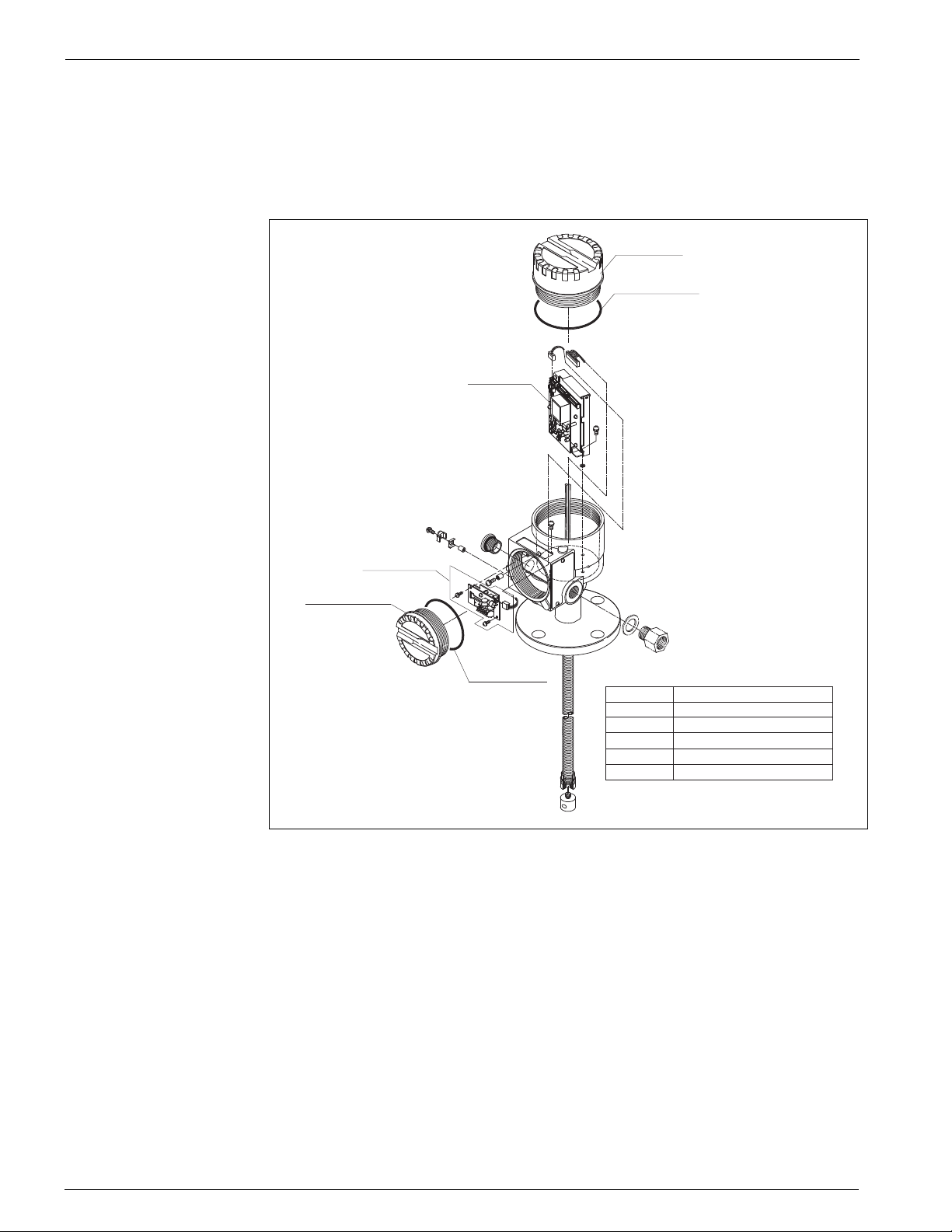
10.2 Spare parts
Spare parts are contained in kits. Spare parts which you can order from Varec for the
4532 ATC are shown with their order numbers in the diagram below. For more
information on service and spare parts, contact Varec.
70106024
017803-0043
70106026
58020200
017802-0008
Figure 10-1:Spare Parts
017803-0044
70106024
017803-0043
70106026
58020200
017802-0008
017803-0044
Cover, El-housing M88 long type
O-ring, EPDM 88-d3
Module assembly(Temp. V187)
Terminal+EMC filter assy.
Cover, (T3) M77
O-ring, EPDM 73-d3
48 Installation and Operations Manual
Page 59
4532 Accessories
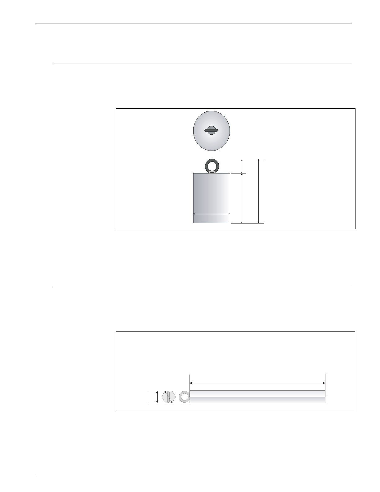
11 Accessories
11.1 Anchor weight (T all profile)
Caution! Installation of anchor weight will cause element position #1 (the lowest temperature
measurement position) to be raised approximately 500 mm (20") from the tank floor.
Material
Weight: SS400 mild carbon steel
Ring: SS400 mild carbon steel
Weight
approx. 16kg
42mm (1.65")
222mm (8.74")
120mm (4.72")
180mm (7.09")
Figure 11-1:Anchor weight dimension
Different dimension, weight, and material anchor are also available. Consult your Varec
representative for further details.
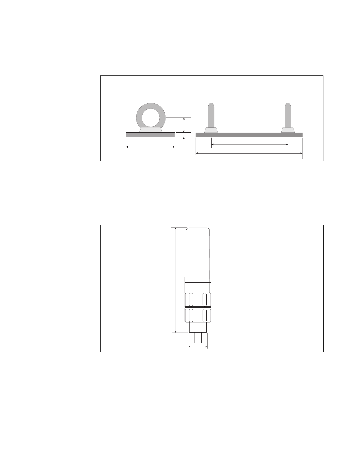
11.2 Anchor weight (Low profile)
The low profile anchor weight is a version for an existing tank installation with a small
nozzle opening for converter and temperature version.
41mm
(1.61")
47mm
(1.85")
Material
Weight: JIS SS400 mild carbon steel
Ring: JIS SS400 mild carbon steel
Weight
approx. 12kg
1000mm (39.37")
Figure 11-2:Low profile anchor weight dimension
Varec, Inc. 49
Page 60
Accessories Average Temperature/Water Bottom Sensor and Converter
11.3 Wire hook, Top anchor
Anchor weights are supplied with SUS316 standard 3 mm diameter tension wire for
attaching anchor weight to temperature probe.
Material
Weight: SS400 mild carbon steel
I-bolt: SS400 mild carbon steel
Weight
approx. 1.5kg
21mm
(0.83")
70 (2.76")
9mm
(0.35")
150 (5.91")
(7.87")
200
Figure 11-3:Wire hook dimension
Actual tensioning can be completed with SUS316 stranded 3 mm diameter tension wire
between Wire hook and Top anchor. Based on the application and installation variable,
type of wire & size, material, and special coatings are available. Please consult your
Varec representative for further details.
Material
Exterior:ADC(aluminium)
Internal parts: Carbon steel
Weight
Approx. 1.2kg
(2.05")
52
190 (7.48")
PT1"
Figure 11-4:Top anchor dimension
Note! The standard process connection of the Top anchor is NPT1" threaded connection.
Different thread size, material, and specification are available. Flange type connection is also available.
50 Installation and Operations Manual
Page 61
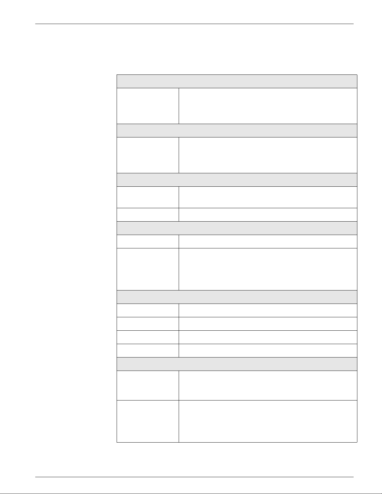
4532 Technical data
12 Technical data
Technical data at a glance:
Application
Application The 4532 ATC performs precise liquid and gas phase average
temperature measurement in bulk storage tank applications.
• Standard 2" flange installation
• Overall 18.5m temperature measurement range
Function and system design
Measuring principle Temperature measurement
• Up to 6 elements spaced evenly over the length of the flexible
tube.
• Pt100, Class A elements
Input
Measured variable Temperature measurement
Temperature conversion range: -20 ~ +100°C
Measuring range -20 ~ +100°C (-4 ~ 212°F)
Output
Output signal • HART protocol (multi drop HART loop connection)
Signal on alarm Error information can be accessed via the following interfaces and
Auxiliary energy
Load HART Minimum load for HART communication: 250
Cable entry see technical document
Supply voltage 16 ~ 30VDC (on multi drop HART loop)
Current consumption Less than 6mA
Performance characteristics
Reference operating
conditions
transmitted digital protocol (refer to the operation manuals on
following instruments)
• Tank Side monitor 4590 TSM
• 6000 Series Servo Tank Gauge
W
• temperature = +25 °C (77 °F) ±5 °C (9 °F)
• pressure = 1013 mbar abs. (14.7 psia) ±20 mbar (0.3 psi)
• relative humidity (air) = 65 % ± 20%
Maximum measured
error
Typical statements for reference conditions, include linearity,
repeatability, and hysteresis:
•Linearity:
• Temperature: ±0.15°C (0.27°F) + number of element deviation
(based on IEC class A standard)
Varec, Inc. 51
Page 62

Technical data Average Temperature/Water Bottom Sensor and Converter
52 Installation and Operations Manual
Page 63
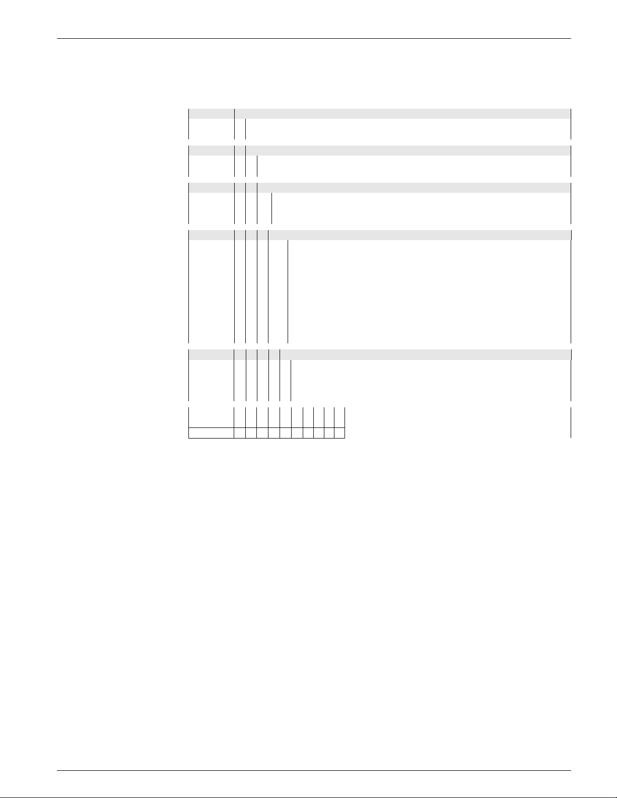
4532 Order Structure
A Order Structure
10 Protection class
7 FM, IS class1, Div.1, Gr. A-D
B ATEX, EEx [ia] IIB T4 -T6
20 Cable entry
B Thread NPT 1/2
D Thread M20
30 Process connection (SUS304)
1 2" 150lbs RF, 304 flange ANSI B16.5
2 DN50 PN0 B1, 304 flange EN1092-1 (DIN2527 C)
9 Special version, to be specified
40 Element #, Interval, Probe range (Below flange to end of probe)
022 ...mm; 2x Pt100; 2 m (min 2,500 mm, max 4,500 mm)
032 ...mm; 3x Pt100; 2 m (min 4,500 mm, max 6,500 mm)
042 ...mm; 4x Pt100; 2 m (min 6,500 mm, max 8,500 mm)
052 ...mm; 5x Pt100; 2 m (min 8,500 mm, max 10,500 mm)
062 ...mm; 6x Pt100; 2 m (min10,500 mm, max 12,500 mm)
023 ...mm; 2x Pt100; 3 m (min 3,500 mm, max 6,500 mm)
033 ...mm; 3x Pt100; 3 m (min 6,500 mm, max 9,500 mm)
043 ...mm; 4x Pt100; 3 m (min 9,500 mm, max 12,500 mm)
053 ...mm; 5x Pt100; 3 m (min 12,500 mm, max 15,500 mm)
063 ...mm; 6x Pt100; 3 m (min 15,500 mm, max 18,500 mm)
50 Specific probe length, Length within selected item at Pos. 040(UP to max. 18,500)
ANot selected
B Anchor weight, tall profile
C Anchor weight, low profile
D Tensio ning wire, wire hook, top anchor
4532 - Complete product designation
Varec, Inc. 53
Page 64

Order Structure Average Temperature/Water Bottom Sensor and Converter
54 Installation and Operations Manual
Page 65
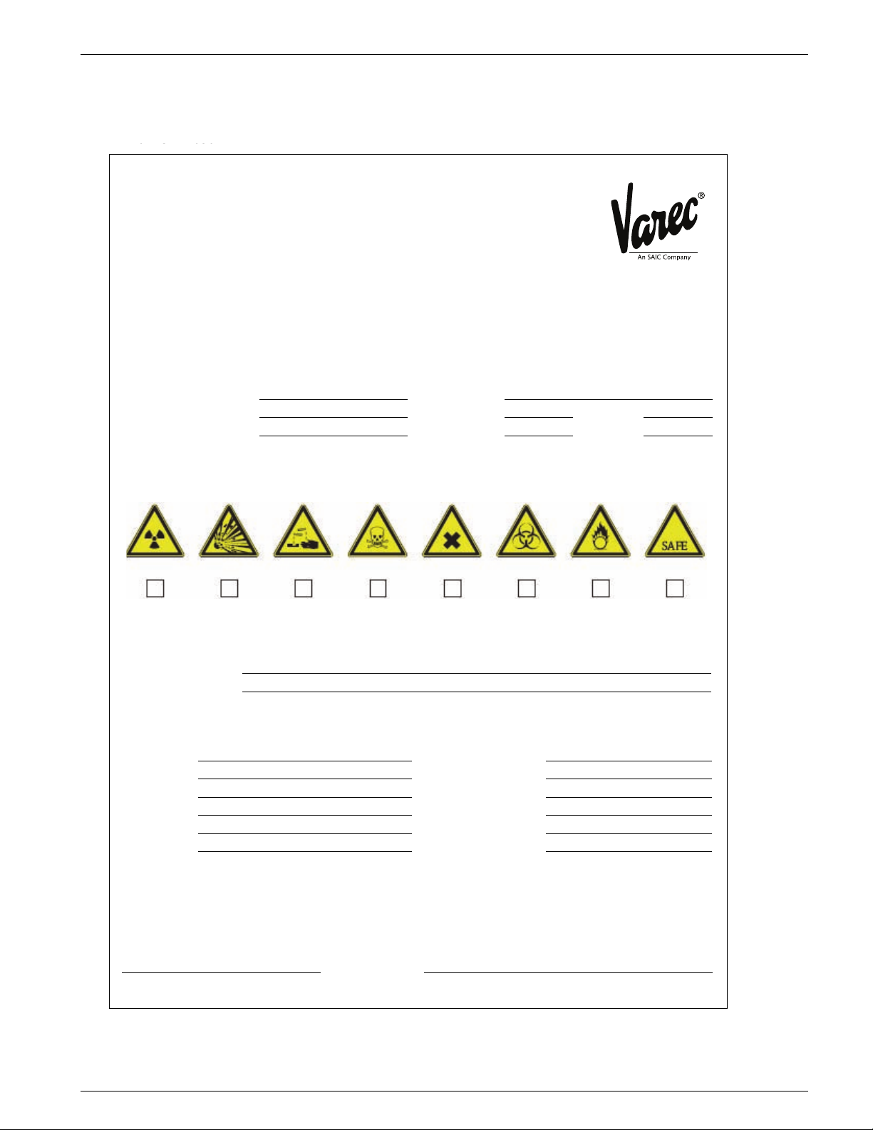
4532 Declaration of Contamination Form
Varec, Inc., an SAIC Company
5834 Peachtree Corners East, Norcross (Atlanta), GA 30092 USA
Tel: +1 (770) 447-9202 Fax: +1 (770) 662-8939
0 G 030
For the safety of our employees and operating equipment, we require that you fill out this form and return it to
Varec with your signature before we can fulfill your order. Please include the completed form with the device and
shipping documents, along with safety sheets and/or specific handling instructions if appropriate.
Warnings for returned device (mark the appropriate symbols)
Company data
I hereby certify that the returned equipment has been cleaned and decontaminated according to standard
industrial practices and is in compliance with all regulations. This equipment poses no health or safety risks due
to contamination.
Type of device/sensor: Serial no.:
Medium/concentration: Temperature: Pressure:
Cleaned with: Conductivity: Viscosity:
radioactive explosive caustic poisonous harmful to
health
biologically
hazardous
inflammable safe
Reason for return
Company Contact person
Department
Address Phone
FAX / e-mail
Order number
Place, date Company stamp and signature
Declaration of Contamination
B Declaration of Contamination Form
Varec, Inc. 55
Page 66

Declaration of Contamination Form Average Temperature/Water Bottom Sensor and Converter
56 Installation and Operations Manual
Page 67

4532 Index
Index
D
Designated use 1
E
explosion-proof type 3
G
Grounding 4
H
Hazardous Substance Datasheet 4
I
installation & operation overview 1
M
Maximum measured error 51
Measuring principle 51
O
Overview, installation & operation 1
S
Safety conventions and symbols 5
Safety instructions 3
Software history 1
Varec, Inc. 57
Page 68

Index Average Temperature/Water Bottom Sensor and Converter
58 Installation and Operations Manual
Page 69

4532
NOTES
Varec, Inc. 59
Page 70

Your offical representative
www.varec.com
Your official representative
5834 Peachtree Corners East, Norcross (Atlanta), GA 30092 USA
© Varec, Inc. An SAIC Company. All Rights Reserved. This document is for information purposes only. Varec, Inc.
makes no warranties, express or implied, in this summary. The names of actual companies and products mentioned
Tel: +1 (770) 447-9202 Fax: +1 (770) 662-8939
herein may be the trademarks of their respective owners.
Varec, Inc.
 Loading...