

Page 1
4000 Tank Gauge Transmitter
Advanced Technology Transmitter for transmission of level and
temperature data from the tankside to inventory management
systems.
Installation and
Operations Manual
IOM003GVAE1007
www.varec.com
5834 Peachtree Corners East, Norcross (Atlanta), GA 30092 USA
Tel: +1 (770) 447-9202 Fax: +1 (770) 662-8939
Varec, Inc.
Page 2

Page 3

4000
Copyright
All rights reserved. Printed in the United States of America. Except as permitted under
the United States Copyright Act of 1976, no part of this publication may be reproduced,
stored in a retrieval system or transmitted in any form or by any means- electronic,
mechanical, photocopying, recording or otherwise- without the prior written permission
of the Publisher:
Varec, Inc.
5834 Peachtree Corners East
Norcross (Atlanta) GA 30096
USA
Trademarks acknowledged
Varec, Inc. recognizes all other trademarks. Trademarks of other products mentioned in
this document are held by the companies producing them.
Varec® is a registered trademark of Varec, Inc. Copyright 2003
FuelsManager® is a registered trademark of Varec, Inc. Copyright 2004
MODBUS® is a registered trademark of Modicon, Inc.
TIWAY® is a registered trademark of Texas Instruments Corporation.
HART® interface is a registered trademark of HART communications foundation.
Rosemount® and Smart Family® are registered trademarks, and HART is a
trademark of Rosemount Inc.
i
Page 4

Tank Gauge Transmitter
Disclaimer of Warranties
The contract between the Seller and the Buyer states the entire obligation of the Seller.
The contents of this document shall not become part of or modify any prior or existing
agreement, commitment or relationship between the Seller and Buyer. There are no
express or implied warranties set out in this document. The only warranties that apply
are those in the existing contract between the Seller and Buyer.
Varec, Inc. products have not been tested by Varec, Inc. under all possible operational
conditions, and Varec, Inc. may not have all the data relative to your application. The
information in this document is not all inclusive and does not and cannot take into
account all unique situations. Consequently, the user should review this product
literature in view of his/her application. If you have any further questions, please contact
Varec, Inc. for assistance.
Limitations of Seller's Liability
In the event that a court holds that this document created some new warranties, Seller's
liability shall be limited to repair or replacement under the standard warranty clause. In
no case shall the Seller's liability exceed that stated as Limitations of Remedy in the
contract between the Seller and Buyer.
Terms of Use
The information provided in this document is provided “as is” without warranty of any
kind. Varec, Inc. disclaim all warranties, either express or implied, including the
warranties of merchantability and fitness for a particular purpose. In no event shall
Varec, Inc. or its suppliers be liable for any damages whatsoever including direct,
indirect, incidental, consequential, loss of business profits or special damages, even if
Varec, Inc. or its suppliers have been advised of the possibility of such damages.
Use of parts that are not manufactured or supplied by Varec, Inc. voids any Varec, Inc.
warranty and relieves Varec, Inc. of any obligation to service the product under warranty.
Varec, Inc. recommends the use of only Varec, Inc. manufactured or supplied parts to
maintain or service Varec, Inc. products.
ii Installation and Operations Manual
Page 5

4000
Safety Precaution Definitions
Caution! Damage to equipment may result if this precaution is disregarded.
Warning! Direct injury to personnel or damage to equipment which can cause injury to
personnel may result if this precaution is not followed.
Safety Precautions
READ AND UNDERSTAND THIS INSTRUCTION MANUAL BEFORE INSTALLING, OPERATING
OR PERFORMING MAINTENANCE ON VAREC 4000 SERIES TANK GAUGE TRANSMITTER.
FOLLOW ALL PRECAUTIONS AND WARNINGS NOTED HEREIN WHEN INSTALLING,
OPERATING OR PERFORMING MAINTENANCE ON THIS EQUIPMENT.
iii
Page 6

Tank Gauge Transmitter
iv Installation and Operations Manual
Page 7

4000
1 Introduction . . . . . . . . . . . . . . . . . . . . . . . . . . . . . . . . . . . . . . . . . . . . . . . .1
1.1 Using This Manual . . . . . . . . . . . . . . . . . . . . . . . . . . . . . . . . . . . . . . . . . . . . .1
1.2 Getting Acquainted with the Advanced Technology Transmitter (ATT) . . . . .1
1.4 Configuration. . . . . . . . . . . . . . . . . . . . . . . . . . . . . . . . . . . . . . . . . . . . . . . . . .2
1.5 Construction . . . . . . . . . . . . . . . . . . . . . . . . . . . . . . . . . . . . . . . . . . . . . . . . . .2
2 Installation . . . . . . . . . . . . . . . . . . . . . . . . . . . . . . . . . . . . . . . . . . . . . . . . .3
2.1 Overview. . . . . . . . . . . . . . . . . . . . . . . . . . . . . . . . . . . . . . . . . . . . . . . . . . . . .3
2.1.1 Unpacking . . . . . . . . . . . . . . . . . . . . . . . . . . . . . . . . . . . . . . . . . . . . . . .3
2.1.2 Storage Prior to Installation. . . . . . . . . . . . . . . . . . . . . . . . . . . . . . . . . . . .3
2.1.3 Becoming Familiar with the ATT . . . . . . . . . . . . . . . . . . . . . . . . . . . . . . . .3
2.1.4 Hardware Configuration . . . . . . . . . . . . . . . . . . . . . . . . . . . . . . . . . . . . . .3
2.3 Grounding the Equipment. . . . . . . . . . . . . . . . . . . . . . . . . . . . . . . . . . . . . . . .5
2.4 Wiring . . . . . . . . . . . . . . . . . . . . . . . . . . . . . . . . . . . . . . . . . . . . . . . . . . . . . . .5
2.4.1 ATT Wiring . . . . . . . . . . . . . . . . . . . . . . . . . . . . . . . . . . . . . . . . . . . . . . .5
2.4.2 Wiring Preparation. . . . . . . . . . . . . . . . . . . . . . . . . . . . . . . . . . . . . . . . . .5
2.4.3 Connecting Input Power . . . . . . . . . . . . . . . . . . . . . . . . . . . . . . . . . . . . . .5
2.4.4 Connecting Host Communication . . . . . . . . . . . . . . . . . . . . . . . . . . . . . . .6
2.5.1 Connecting the Handheld Terminal . . . . . . . . . . . . . . . . . . . . . . . . . . . . .10
2.5.2 Wiring Completion . . . . . . . . . . . . . . . . . . . . . . . . . . . . . . . . . . . . . . . . .10
2.5.3 Installation Checkout . . . . . . . . . . . . . . . . . . . . . . . . . . . . . . . . . . . . . . .10
2.5.4 Installation Checklist . . . . . . . . . . . . . . . . . . . . . . . . . . . . . . . . . . . . . . .10
3 Configuration . . . . . . . . . . . . . . . . . . . . . . . . . . . . . . . . . . . . . . . . . . . . .11
3.1 Configuration Parameters. . . . . . . . . . . . . . . . . . . . . . . . . . . . . . . . . . . . . . .11
3.2 1200 Hand Held Terminal. . . . . . . . . . . . . . . . . . . . . . . . . . . . . . . . . . . . . . .11
3.3 Terminal Mode Operation. . . . . . . . . . . . . . . . . . . . . . . . . . . . . . . . . . . . . . .13
3.4.5 Notes on Menu Items. . . . . . . . . . . . . . . . . . . . . . . . . . . . . . . . . . . . . . .18
3.5 Quick Setup . . . . . . . . . . . . . . . . . . . . . . . . . . . . . . . . . . . . . . . . . . . . . . . . .19
3.5.6 Imperial Decimal 1800 Series Transmitter Quick Setup . . . . . . . . . . . . . . .24
3.5.7 0-20 Meters 1800 Series Transmitter Quick Setup. . . . . . . . . . . . . . . . . . .24
3.5.8 0-30 Meters 1800 Series Transmitter Quick Setup. . . . . . . . . . . . . . . . . . .24
4 Maintenance and Troubleshooting . . . . . . . . . . . . . . . . . . . . . . . .27
4.1 Maintenance . . . . . . . . . . . . . . . . . . . . . . . . . . . . . . . . . . . . . . . . . . . . . . . . .27
4.2 Battery Replacement . . . . . . . . . . . . . . . . . . . . . . . . . . . . . . . . . . . . . . . . . .27
4.3.1 ATT Error Status Conditions . . . . . . . . . . . . . . . . . . . . . . . . . . . . . . . . . .28
4.5 ATT Configuration Error Checking . . . . . . . . . . . . . . . . . . . . . . . . . . . . . . . .29
4.7 Host Communication Loopback Tests . . . . . . . . . . . . . . . . . . . . . . . . . . . . .30
5 Specifications . . . . . . . . . . . . . . . . . . . . . . . . . . . . . . . . . . . . . . . . . . . . .31
5.1 Specifications and Physical Characteristics . . . . . . . . . . . . . . . . . . . . . . . . 31
v
Page 8

5.1.1 Environmental . . . . . . . . . . . . . . . . . . . . . . . . . . . . . . . . . . . . . . . . . . . 31
5.1.2 Physical. . . . . . . . . . . . . . . . . . . . . . . . . . . . . . . . . . . . . . . . . . . . . . . . 31
5.1.3 Input Power . . . . . . . . . . . . . . . . . . . . . . . . . . . . . . . . . . . . . . . . . . . . . 31
5.1.4 Level Measurement . . . . . . . . . . . . . . . . . . . . . . . . . . . . . . . . . . . . . . . 32
5.2.1 Explosion Proof . . . . . . . . . . . . . . . . . . . . . . . . . . . . . . . . . . . . . . . . . . 33
5.2.2 Intrinsic Safety . . . . . . . . . . . . . . . . . . . . . . . . . . . . . . . . . . . . . . . . . . . 33
6 Order Codes . . . . . . . . . . . . . . . . . . . . . . . . . . . . . . . . . . . . . . . . . . . . . . 35
7 Theory of Operation. . . . . . . . . . . . . . . . . . . . . . . . . . . . . . . . . . . . . . . 37
7.1 Overview . . . . . . . . . . . . . . . . . . . . . . . . . . . . . . . . . . . . . . . . . . . . . . . . . . . 37
7.2 CPU Board. . . . . . . . . . . . . . . . . . . . . . . . . . . . . . . . . . . . . . . . . . . . . . . . . . 37
7.3 Status Inputs and Outputs . . . . . . . . . . . . . . . . . . . . . . . . . . . . . . . . . . . . . . 38
7.4 ATTI Communications Port . . . . . . . . . . . . . . . . . . . . . . . . . . . . . . . . . . . . . 38
7.5 Host Communications Interfaces. . . . . . . . . . . . . . . . . . . . . . . . . . . . . . . . . 38
7.6 Level Measurement . . . . . . . . . . . . . . . . . . . . . . . . . . . . . . . . . . . . . . . . . . . 38
Tank Gauge Transmitter
7.6.1 Back-up Battery . . . . . . . . . . . . . . . . . . . . . . . . . . . . . . . . . . . . . . . . . . 38
7.6.2 Damping . . . . . . . . . . . . . . . . . . . . . . . . . . . . . . . . . . . . . . . . . . . . . . . 38
7.7 Encoder Battery Backup . . . . . . . . . . . . . . . . . . . . . . . . . . . . . . . . . . . . . . . 39
7.8 Temperature Measurement . . . . . . . . . . . . . . . . . . . . . . . . . . . . . . . . . . . . . 39
7.9 Host Communication . . . . . . . . . . . . . . . . . . . . . . . . . . . . . . . . . . . . . . . . . . 39
7.10 Mark/Space Host Interface . . . . . . . . . . . . . . . . . . . . . . . . . . . . . . . . . . . . . 40
7.11 Modbus Support over Mark/Space Host Interface. . . . . . . . . . . . . . . . . . . . 41
7.12 Compatibility with Varec Tank Polling Unit . . . . . . . . . . . . . . . . . . . . . . . . . 41
8 ATT Family of Products . . . . . . . . . . . . . . . . . . . . . . . . . . . . . . . . . . . 43
8.1 Model 4040 Display Unit . . . . . . . . . . . . . . . . . . . . . . . . . . . . . . . . . . . . . . . 43
8.2 Model 4050 Digital Input/Output Unit. . . . . . . . . . . . . . . . . . . . . . . . . . . . . . 44
8.2.1 Digital Outputs . . . . . . . . . . . . . . . . . . . . . . . . . . . . . . . . . . . . . . . . . . . 44
8.2.2 Digital Inputs . . . . . . . . . . . . . . . . . . . . . . . . . . . . . . . . . . . . . . . . . . . . 44
8.2.3 Relay Specifications . . . . . . . . . . . . . . . . . . . . . . . . . . . . . . . . . . . . . . . 44
9 Modbus Implementation . . . . . . . . . . . . . . . . . . . . . . . . . . . . . . . . . . 45
9.1 Introduction . . . . . . . . . . . . . . . . . . . . . . . . . . . . . . . . . . . . . . . . . . . . . . . . . 45
9.2 Implementation . . . . . . . . . . . . . . . . . . . . . . . . . . . . . . . . . . . . . . . . . . . . . . 45
9.3 Configuration . . . . . . . . . . . . . . . . . . . . . . . . . . . . . . . . . . . . . . . . . . . . . . . . 45
9.5 Integer Registers . . . . . . . . . . . . . . . . . . . . . . . . . . . . . . . . . . . . . . . . . . . . . 47
9.5.1 Integer Data. . . . . . . . . . . . . . . . . . . . . . . . . . . . . . . . . . . . . . . . . . . . . 48
9.5.3 Character Data. . . . . . . . . . . . . . . . . . . . . . . . . . . . . . . . . . . . . . . . . . . 49
9.5.5 Packed Bit Data . . . . . . . . . . . . . . . . . . . . . . . . . . . . . . . . . . . . . . . . . . 50
9.6.1 Floating-Point Data . . . . . . . . . . . . . . . . . . . . . . . . . . . . . . . . . . . . . . . . 51
9.6.2 The Two 16-bit Registers Format . . . . . . . . . . . . . . . . . . . . . . . . . . . . . . 51
vi Installation and Operations Manual
Page 9

4000
9.6.3 Floating Point Data . . . . . . . . . . . . . . . . . . . . . . . . . . . . . . . . . . . . . . . .51
9.6.5 Floating Point Data . . . . . . . . . . . . . . . . . . . . . . . . . . . . . . . . . . . . . . . .52
9.6.6 Floating Point Data . . . . . . . . . . . . . . . . . . . . . . . . . . . . . . . . . . . . . . . .52
9.7.1 Status Bit Data . . . . . . . . . . . . . . . . . . . . . . . . . . . . . . . . . . . . . . . . . . .53
9.8 Exception Responses. . . . . . . . . . . . . . . . . . . . . . . . . . . . . . . . . . . . . . . . . .53
9.10 Loopback Test . . . . . . . . . . . . . . . . . . . . . . . . . . . . . . . . . . . . . . . . . . . . . . .54
9.11 Hardware Implementation. . . . . . . . . . . . . . . . . . . . . . . . . . . . . . . . . . . . . . .54
9.12 Integer Register Map . . . . . . . . . . . . . . . . . . . . . . . . . . . . . . . . . . . . . . . . . .55
9.14 Status Bit Register Map . . . . . . . . . . . . . . . . . . . . . . . . . . . . . . . . . . . . . . . .59
10 Optional Interfaces . . . . . . . . . . . . . . . . . . . . . . . . . . . . . . . . . . . . . . . .61
10.1 4000TIFMO. . . . . . . . . . . . . . . . . . . . . . . . . . . . . . . . . . . . . . . . . . . . . . . . . .61
10.2 4000GEFMO. . . . . . . . . . . . . . . . . . . . . . . . . . . . . . . . . . . . . . . . . . . . . . . . .61
10.3 4000LJFMO . . . . . . . . . . . . . . . . . . . . . . . . . . . . . . . . . . . . . . . . . . . . . . . . .61
10.4 4000MXFMO. . . . . . . . . . . . . . . . . . . . . . . . . . . . . . . . . . . . . . . . . . . . . . . . .61
10.6 4000GMFMO . . . . . . . . . . . . . . . . . . . . . . . . . . . . . . . . . . . . . . . . . . . . . . . .62
Glossary . . . . . . . . . . . . . . . . . . . . . . . . . . . . . . . . . . . . . . . . . . . . . . . . . . . . . .63
vii
Page 10

Tank Gauge Transmitter
viii Installation and Operations Manual
Page 11
4000 Introduction
g
1 Introduction
1.1 Using This Manual
This manual is designed to assist the user with the installation, configuration, operation, maintenance, and
troubleshooting of the Varec Model 4000 Advanced Technology Transmitter (ATT).
1.2 Getting Acquainted with the Advanced Technology Transmitter (ATT)
The Varec Model 4000 Advanced Technology Transmitter (ATT), in conjunction with a host, represents a data
acquisition and communications system for use in liquid level measurement and/or other measurement applications.
Liquid level measurement is provided by the Advanced Technology Transmitter coupled to a Varec Model 2500 or other
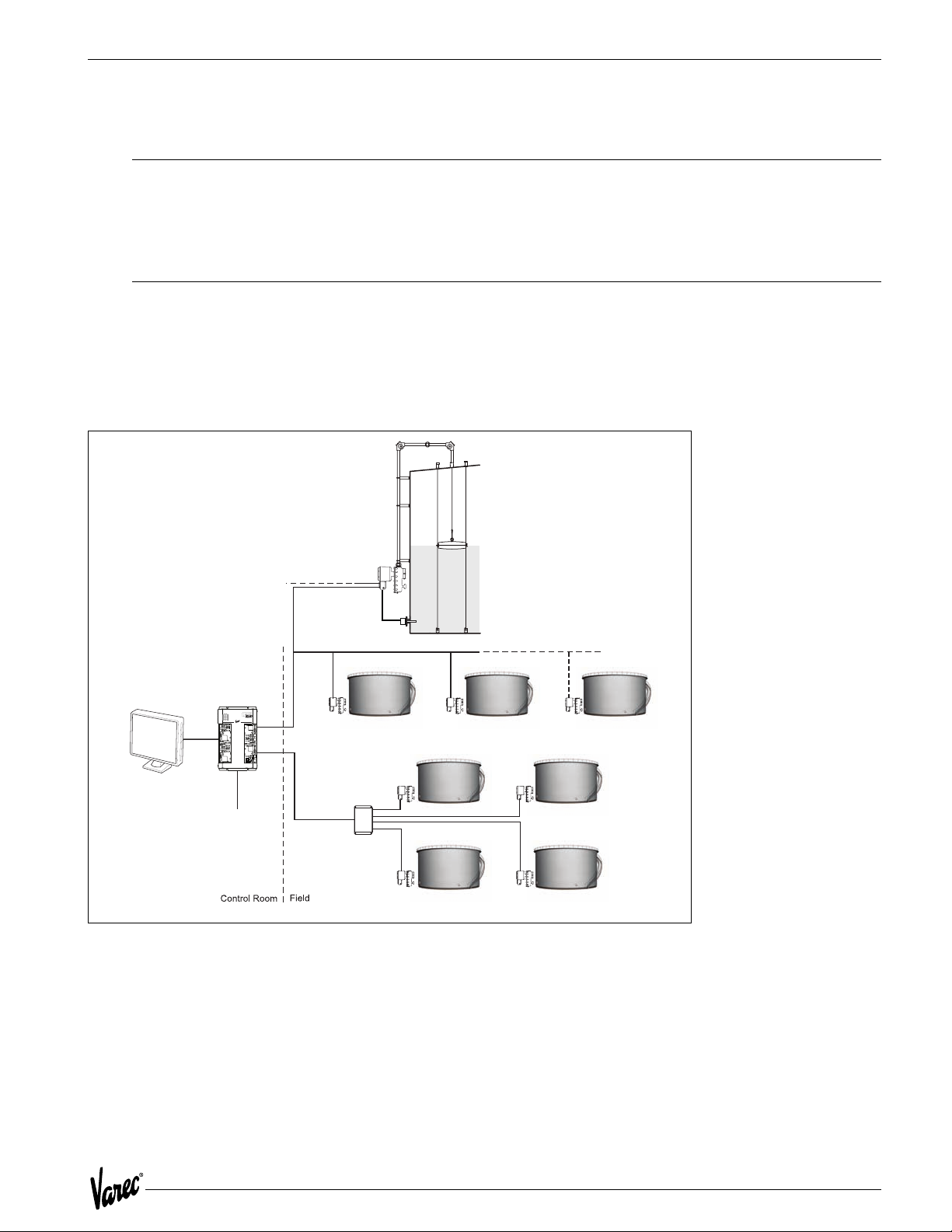
level gauge, as shown in Figure 1-1.
Tank Gauge
and
Transmitter
Power
Loop
Communcations
3-wire
RTD
8130 RTU
FuelsManager
Software
or
8300 TGI
CPU
+24V
+5V
COMM
I/O
+15V
ERROR
-15V
Communications
between DCS/PLCs
for control capabilities
Field
Junction Box
Star Communcations e.
Figure 1-1: Tank Installation with Model 4000 ATT
Loop Communcations
. Mark/Space
1
Page 12
Introduction Tank Gauge Transmitter
1.3 Operation
The ATT uses an incremental counting technique for determining liquid level. An initial level is identified as part of the
calibration procedure. Changes to that level are determined through incremental increases or decreases detected by
the ATT.
The host computer collects measurement information by polling the Advanced Technology Transmitter over a variety
of communication interfaces such as EIA485 and Mark/Space. Several communication protocols are supported. Among
them are Modbus and Mark/Space.
1.4 Configuration
The Varec Model 1200 Handheld Terminal is used to configure the ATT. It connects to the same ATTI bus used to
interconnect other input/output devices to the ATT. There is a special connection located inside the junction box for
the Handheld Terminal.
1.5 Construction
The Advanced Technology Transmitter is housed within an aluminum enclosure. The enclosure and assembly meet
explosion proof requirements and are environmentally sealed to prevent internal exposure to contamination.
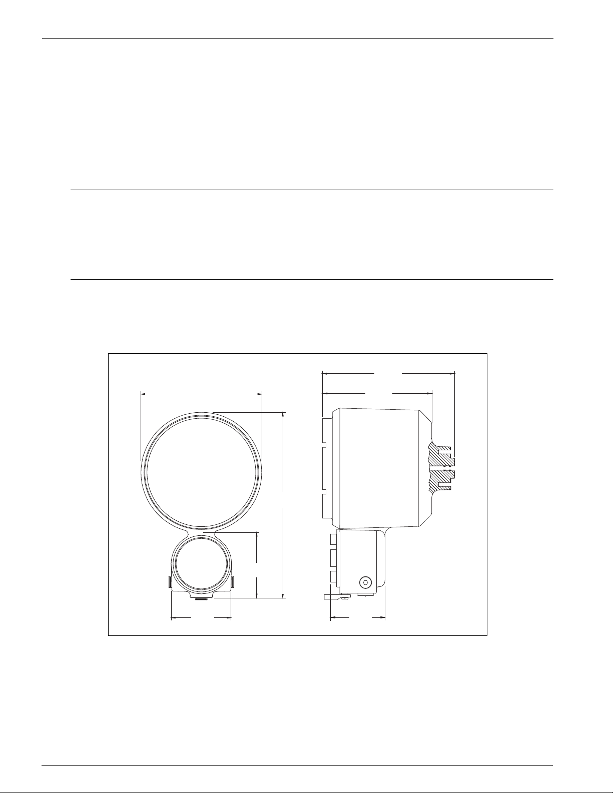
7.5 "
(190 mm)
12 "
(308 mm)
4 "
(101 mm)
3.7 "
(94 mm)
Figure 1-2: Model 4000 Advanced Technology Transmitter Assembly
3.4 "
(86 mm)
8 "
(203 mm)
6.8 "
(172 mm)
2 Installation and Operations Manual
Page 13

4000 Installation
2 Installation
2.1 Overview
This section contains instructions for unpacking, mounting, grounding, and wiring the Varec Model 4000 Advanced
Technology Transmitter (ATT) assembly. An installation checklist is also included.
Warning! To avoid electric shock and possible injury, do not perform any service procedures other than those specified in this
manual. These installation instructions are for use by qualified service technicians.
Figure 2-1: Model 4000 ATT mounted on Model 2500 ATG
2.1.1 Unpacking
Remove the ATT from the shipping container and inspect it for evidence of shipping or handling damage. Report any
shipping damage to the carrier. Verify that the contents of the shipping container agrees with the packing list.
2.1.2 Storage Prior to Installation
If the ATT is to be stored prior to installation, it should be repackaged in its shipping container and stored in a
temperature and humidity controlled environment.
2.1.3 Becoming Familiar with the ATT
The ATT is housed within an explosion proof enclosure. A cover is provided to permit access to both the electronics
and backup batteries.
3/4- and 2 1/2-inch NPT plugs are provided for wiring access. Wiring to the ATT consists of connecting power, host
communication, RTD input and an optional ground connection.
2.1.4 Hardware Configuration
All configuration is performed using the Model 1200 Handheld Terminal or a download from a host computer.
However, certain parameters such as communication address and speed must be configured via the Model 1200
Handheld Terminal.
3
Page 14
Installation Tank Gauge Transmitter
e
E
2.2 Mounting the Equipment
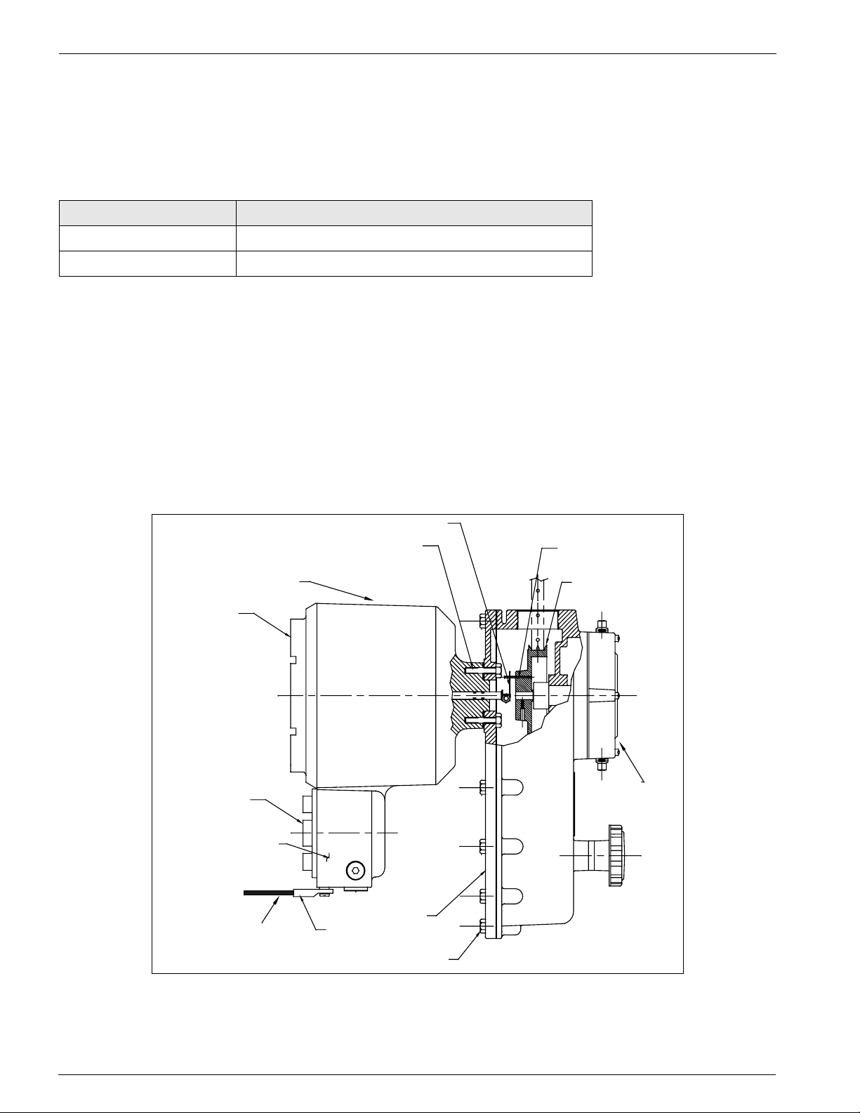
The ATT is bolted to the Model 2500 Automatic Tank Gauge head as illustrated in Figure 2-2. It may also be mounted
to Endress+Hauser, Sakura, Tokyo-Keiso, Shand & Jurs, and Gauging Systems, Inc. float and tape gauges with the
Endress+Hauser adapter shown in the following table.
Part Number Gauge Adapter Kit
13-05956-102 L&J (Shand & Jurs) 92513, 92514, 92020, 92030
13-05956-202 Whessoe 2006, 2026, 2036 and L&J (Shand & Jurs) 92006
Mounting the ATT to the Level Gauge is accomplished in the following manner:
1. Remove the back cover of the Level Gauge.
2. Remove the access cap from the back cover of the Level Gauge.
3. Mount the ATT in place of the access cap, making certain that the word "TOP" cast into the housing lines up with
the top of the Level Gauge back cover.
4. Install the Level Gauge back cover with the transmitter in the Level Gauge. Make certain that the slot in the ATT
drive coupling engages with the pin on the tape sheave of the Level Gauge.
5. Proceed with field wiring.
Back
cover
Junction
box cover
Integral junction
box
Drive coupling
5/16-18 X 1 mounting bolts (4 places)
5/16 split lock washers (4 places)
Transmitter
Pin drive
Sprocket Sheave
2500
Automatic
Tank Gaug
Back Cover
xternal enclosure ground
connection by installer
External Ground Lug
Gauge cover mounting
bolts (15 places)
Figure 2-2: ATT Mounting Diagram
4 Installation and Operations Manual
Page 15

4000 Installation
2.3 Grounding the Equipment
Warning! The ATT must be grounded before communication and power connections are made.
An external grounding lug is provided on the ATT. A connection from the ground lug to earth ground must be made
before any other wiring connections are made.
Note! For adequate/proper operation of the ATT lightning arrestor, a ground strap must be attached to the ATT. Grounding
through mounting kits or pipe coupling is not adequate.
Note! Properly seal all ports to prevent moisture or other contamination from entering the wiring compartment.
2.4 Wiring
Connections should be made in a conventional manner according to local or plant electric codes.
Warning! Explosion-proof seals must be installed in all wiring entries. Any unused entries must be plugged with pipe plugs and
secured with Loctite®, or equivalent.
2.4.1 ATT Wiring
Wiring the ATT is described in the following paragraphs. The wiring diagram provided in Figure 2-3 on page 6 should
be used in conjunction with these wiring instructions.
2.4.2 Wiring Preparation
Remove the two thread protectors from the 1/2-inch NPT conduit entries at the top and bottom of the ATT. Remove
the rear cover from the ATT housing.
2.4.3 Connecting Input Power
Warning! When connecting DC power leads to the ATT, make certain that power is OFF.
The ATT operates on a 24-48 volts DC power source. The input power connection to the ATT is accomplished in the
following manner.
Connect the positive side of the power supply to terminal 10, B+, and the negative side to terminal 9, B-, of the
terminal block assembly. See Figure 2-3 on page 6.
5
Page 16
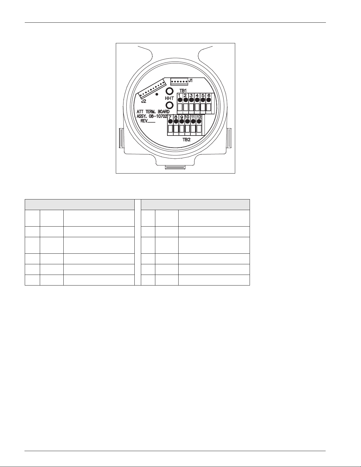
Installation Tank Gauge Transmitter
Figure 2-3: ATT Field Terminal Block Wiring
Terminal Block One TB1 Terminal Block Two TB2
1 L+ = ATTI expansion Bus +
power
2 HPORT = ATTI bus HART Signal 11 M = Mark or EIA485 -
3 L- = ATTI expansion Bus -
power
4 C = RTD C lead 9 B - = ATT - power
5 B = RTD B lead 8 -- = Reserved
6 A = RTD A lead 7 -- = Reserved
12 S = Space or EIA485 +
10 B + = ATT + power
2.4.4 Connecting Host Communication
The procedure used to wire the ATT to the host computer depends on the type of host interface option ordered with
the ATT.
6 Installation and Operations Manual
Page 17
4000 Installation
2.4.5 ATT EIA485 Wiring
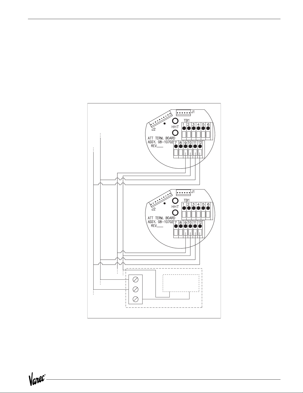
The ATT uses a 2-wire EIA485 hardware interface to communicate with the Modbus master. EIA485 is a high speed
differential communications network which allows up to 32 devices to operate on one network. The ATT and Modbus
master share a twisted pair of wires to communicate. Figure 2-4 illustrates the typical EIA485 wiring.
The communication distance that EIA485 can reliably travel is dependent on baud rate (communication speed), wire
quality, environmental noise, wiring configuration, and the number of multi-dropped ATTs. The recommended wire
for EIA485 systems is 18-gauge or larger, shielded, twisted pairs. The shield should be earth grounded at the Modbus
master (control system or computer end). The shield at the ATT should be open. The ATT B- power line acts as a
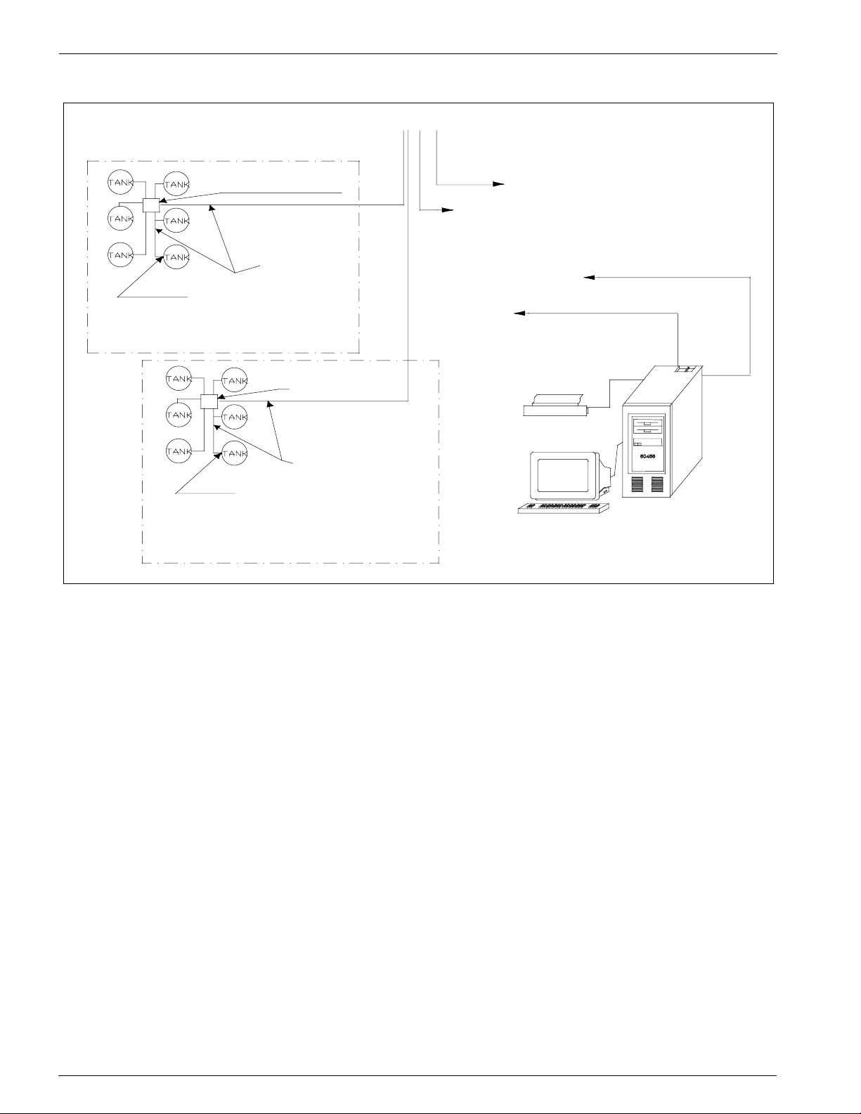
common reference tie to the Modbus master. Figure 2-5 on page 8 illustrates the EIA485 Modbus system.
TB2
TB2
Power Supply
6
5
4
+48
VDC Common
Figure 2-4: Typical EIA485 Wiring
RTU 8130 with 8230 expansion module
7
Page 18
Installation Tank Gauge Transmitter
Field Junction Box
Model 4000 ATT
Transmitters*
Model 4000 ATT
* Up to 31 units with
5000 ft. max. wiring distance
using good quality wire.
Two 18 AWG
twisted pair
cables
Field Junction Box
EIA85 comm.
with MODBUS to FIC
Two 18 AWG
twisted pair cables
Transmitters*
Area 0
Area 1
RTU 8130
Model 8130 with optional
48 VDC power supply.
110/220 VAC 50/60 Hz.
RS232 To FuelsManager
or other MODBUS master
RS232 serial port
50 feet max to FIC
Office Printer
Host Computer Interface
certified by Honeywell
FuelsManager
MODBUS interface is
Figure 2-5: Typical EIA485 System Wiring
8 Installation and Operations Manual
Page 19

4000 Installation
2.4.6 ATT Mark/Space Wiring
For an ATT using the Mark/Space field communications option, the following additional wiring connections must be
made. (Refer to Input Power Wiring in Section 6 to determine the minimum wire size required.). See Figure 2-6.
• Run two twisted pairs of 18 AWG wire (Mark/Space wires) into the ATT through the conduit entry along with the
48 VDC power wiring.
• Connect the Mark line to terminal 11, M/485-, and the Space line to terminal 12,
S/485+, on the terminal block assembly.
8203 With 8210
expansion module
Field Junction Box
4 Conductor
Cable
18 AWG
Shielded
To Other
4-Wire
Transmitters
in Area 0
Ground shield at RTU8130 ONLY!
Do NOT ground shield at transmitter.
Details of RTU8130 with 8210 expansion
module and ATT termination board wiring
External
Power Supply
Varec
Model 4000
ATT
Figure 2-6: Typical Mark/Space Field Wiring
9
Page 20

Installation Tank Gauge Transmitter
2.5 Connecting the RTD
The following list shows how the ATT is wired to an RTD device. The ATT’s temperature circuit is designed to work
with a platinum or copper 3-wire RTD.
2.5.1 Connecting the Handheld Terminal
Figure 2-3 on page 6 shows how the 1200 Hand Held Terminal is connected to the ATTI bus on the ATT. The Model
268 can also be used to configure the ATT.
Warning! The 1200 Hand Held Terminal on the ATT is not Intrinsically Safe. Care must be taken to only use in a non-hazardous
environment
Wire as follows:
• Connect the RTD's A terminal to the ATT's terminal 6, A.
• Connect the RTD's B terminal to the ATT's terminal 5, C.
• Connect the RTD's C terminal to the ATT's terminal 4, C.
2.5.2 Wiring Completion
Caution! Do not overtighten metal plugs used to seal wiring compartment ports. Overtightening may damage the housing.
Properly seal the 1/2-inch NPT conduit entry. Install cover and tighten to ensure that the O-ring seal is adequately
compressed. Proper sealing of all ports is necessary to prevent moisture or other contamination from entering the
wiring compartment.
2.5.3 Installation Checkout
After a thorough check that all connections are correctly made and that all covers and plugs are installed, turn on
power to the ATT. Proceed to Chapter 3, Configuration.
2.5.4 Installation Checklist
The steps required in the installation process are summarized in the following checklist. Since each step is detailed
specifically with accompanying notes, cautions, and warnings, be sure to refer to the sub-sections indicated for further
information.
Step Sub-Section(s) Reference
Unpack the ATT and check the packing list. Unpacking
Verify that the required input power is available. Mounting the ATT, Wiring
Mount the ATT. Mounting the Equipment
Ground the ATT. Grounding the Equipment
Route the conduit between the ATT and other
devices and seal all ports.
Wire the host communications. Connecting Host Communication
Wire the RTD Connecting the RTD
Wire the input power connections. Connecting Input Power
Apply power to the ATT. Installation Checkout
Wire the Model 1200 Handheld Terminal Connecting Handheld Terminal
Proceed to ATT configuration procedure. ATT Configuration (Section 3)
Wiring Completion
10 Installation and Operations Manual
Page 21

4000 Configuration
3 Configuration
The Varec Model 4000 Advanced Technology Transmitter (ATT) must be configured for the specific tank, attached
sensors, and host interface. This section provides detailed information on ATT configuration.
The ATT can be configured with a 1200 Hand Held Terminal or from a host program such as Varec TankView.
3.1 Configuration Parameters
Configuration parameters associated with ATT operation are entered and modified using the Model 1200 and can be
divided into the following areas:
• General Configuration - includes units of measure, level calibration, temperature type selection, and alarm
setpoints.
• Host Configuration - includes the type of host interface used, baud rate selection, and emulation modes for other
level transmitters.
3.2 1200 Hand Held Terminal
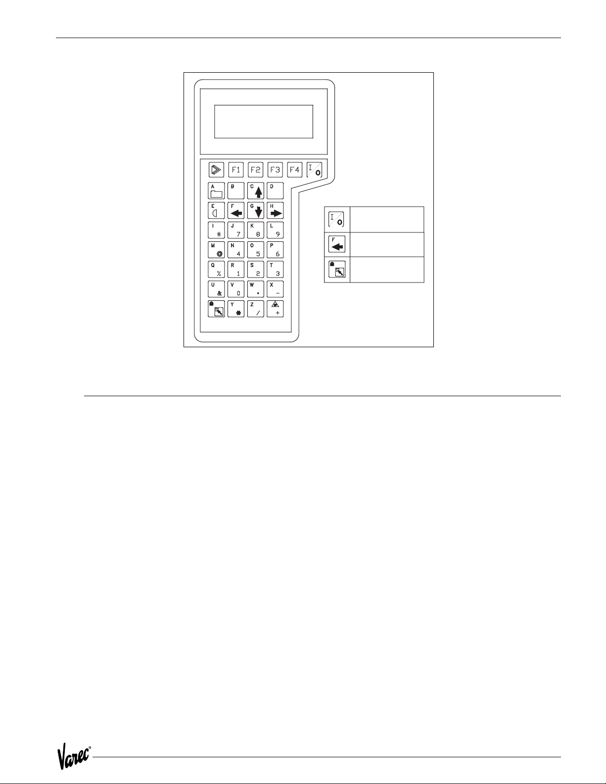
The ATT can be used with a 1200 Hand Held Terminal, see Figure 3-3 on page 13. The Model 1200 provides a local
terminal interface to configure the ATT and encoder at tankside. It is connected to the ATTI bus. It can be physically
attached via two banana plugs located inside the terminal block housing.
The ATT uses the Model 1200 in a different mode of operation. Normally, the Model 1200 polls the ATTI BUS device,
recognizes it, and goes into an internal menu system that is specifically tailored to that ATTI Bus device. The ATT
however, uses the Model 1200 in what is called ASCII Terminal mode. In this mode, the Model 1200 sends keyboard
activity to the ATT and displays screen information from the ATT. The ATT can not be configured with the Rosemount
Model 275 Terminal.
Because of the way the ASCII Terminal mode works on the Model 1200, the ATT is unable to poll any ATTI BUS device
while communicating to it. The ATT goes from an operational mode to an off-line mode. The operational mode is
automatically switched to when the Model 1200 is removed from the ATTI BUS bus.
Warning! The 1200 Hand Held Terminal on the ATT is not Intrinsically Safe. Care must be taken to only use in a non-hazardous
environment.
Function keys F1 through F4, defined in Figure 3-1 on page 11, are used for basic scrolling of the ATT menus and
selection of configuration parameters.
Function Key Description
HELP Help Message
F1 Scroll Up
F2 Scroll Down
F3 Alter/Backspace
F4 Enter
Previous Function [Ü] Return to previous menu or abort data entry
Table 3-1: Model 1200 Function Keys
Alpha and numeric information is entered from the keypad directly. Numeric data is entered using a single keystroke,
while alpha information is entered with a two-key combination. The two-key combination for alpha data consists of a
shift key followed by a numeric key to select the desired alpha character.
11
Page 22

Configuration Tank Gauge Transmitter
For example, to enter the alpha character "N"; first press the shift key, then press the number 4. To enter the alpha
character "R"; first press the shift key, then press the number 1.
Terminal Mode Configuration
When the Model 1200 is connected to the ATTI Bus and turned on, a blank screen will appear on the Model 1200 after
a self test sequence. Pressing any key will cause the following screen to appear on the Model 1200 display:
The version indicated is the software version of the ATT.
Enter a "D" (to select Display Mode entries) or an "A" (to select Alter Mode entries) and press F4 (Enter).
If the Display Mode is selected with a "D", current status and configuration data may be examined but cannot be
modified. This mode is useful for verifying ATT configuration. This mode cannot be used to actively monitor ATT
operation, as normal ATT operation is suspended when the Model 1200 is connected.
Figure 3-1: ATT Alter Mode Menu Tree
If the Alter Mode is selected with an "A", all applicable configuration parameters can be modified. Figure 3-2 on
page 12 illustrates the display mode menu tree and Figure 3-1 on page 12 illustrates the Alter Mode menu tree. The
menu tree groups related items under separate menus and sub-menus. The menu grouping is provided to permit the
field operator to configure and display items in a related and logical order. Once a menu is selected, the operator can
scroll through related items.
Figure 3-2: ATT Display Mode Menu Tree
12 Installation and Operations Manual
Page 23
4000 Configuration
ON / OFF
Previous Function
Shift
Figure 3-3: 1200 Hand Held Terminal
3.3 Terminal Mode Operation
The 1200 Hand Held Terminal is used to scroll through the various ATT menus. Basic scroll and selection operations
are performed using the four function keys (F1 through F4) immediately below the display.
Line 1 of the display contains the menu title. Lines 2 and 3 are item display lines. Line 4 is an error message/status line.
If the item displayed on line 2 is preceded with an "M>", the item being displayed is a menu. You can select the menu
by pressing F4 (Enter). If the item is preceded by a "C>" the item being displayed is a command that can be executed
by pressing F4 (Enter).
Where:
F1 = Up
F2 = Down
F3 = Alter
F4 = Enter
13
Page 24

Configuration Tank Gauge Transmitter
3.4 Menu Operation
For example, when the Main Menu is displayed on the top line, pressing F1 (Up) will scroll up through the possible
main menu selections while pressing F2 (Down) will scroll down through the possible main menu selections.
Pressing F4 (Enter) will cause the selection of the sub-menu displayed on lines two and three (such as Config Menu).
Scrolling through a sub-menu is performed in the same manner as scrolling through the Main Menu using the F1 and
F2 keys.
To return to the Main Menu, press the PREVIOUS FUNCTION key [Ü], as shown in Figure 3-3 on page 13.
When a parameter is encountered which is to be changed, pressing the F3 key (Alter) will cause the display of the
current parameter in a form which permits its modification.
When a specific set of parameters is available, the F1 and F2 keys can be used to scroll through the valid selections.
When the desired selection is displayed, pressing the F4 key (Enter) will cause selection of the new parameter. When
the parameter consists of numeric or free format characters, the Model 1200 keyboard can be used to enter the
parameter. Note that parameter alteration is not final until the session is completed with the EXIT AND SAVE command
from the Main Menu.
To complete parameter alteration, scroll through the Main Menu until the following display is presented, then press
F4 (Enter) to exit and save the altered parameters.
If parameter alteration is to be aborted (new parameters not saved), scroll through the Main Menu until the following
display is presented and press F4 (Enter) to quit without saving alterations. The QUIT or EXIT AND SAVE commands
must be initiated before turning off or disconnecting the 1200 Hand Held Terminal.
14 Installation and Operations Manual
Page 25

4000 Configuration
3.4.1 Main Menu
Main Menu Description
Quick Setup
Summary Menu
2
1
Config Menu Contains ATT configuration menu items. See table below.
Host Menu
Exit and Save
1
2
Initializes the ATT configuration parameters to a variety of
preset configurations. Eng Frac 1900, Eng Dec 1900, 0-30 m
1900, 0-20m 1900, Eng Frac 1800, Eng Dec 1800, 0-30 m
1800, 0-20m 1800, Imperial Modbus, or Metric Modbus are
valid. Use F1/F2 keys to select. See section below for details.
Warning! Warning! Using Quick Setup will overwrite any old
configuration in the ATT and should not be used
if only some configuration parameters are to be
changed.
Contains the ATT's process variable data and diagnostic status
conditions. See table below.
Contains ATT host communication related configuration menu
items. See table below.
Must be used to exit the Alter Mode if configuration data
modified are to be used.
Quit/Exit Used to quit Alter Mode without saving. Also displayed as Exit
in display mode.
15
Page 26

Configuration Tank Gauge Transmitter
3.4.2 Summary Menu
Summary Menu Description
Level Current level.
Temperature Current temperature
RTD Resistance RTD resistance measured
Cfg Error Type Configuration error type detected.
Power Log Number of times unit has gone through a power down cycle
since it was last configured. Going into Alter Mode and using
'Exit and Save' resets this value to 0.
Bad CPU Board Stat
Bad RAM Stat
Bad EProm Stat
Bad EEProm Stat
3
3
3
Bad EECksum Stat
Bad Comm Board
Bad Level Stat
Bad Temp Stat
Low Battery Stat
Crit Hi Level Stat
Adv Hi Level Stat
Adv Lo Level Stat
Crit Lo Level Stat
3
3
3
3
3
3
3
Crit Hi Temp Stat
Adv Hi Temp Stat
Adv Lo Temp Stat
Crit Lo Temp Stat
3
3
3
3
3
3
3
Bad CPU Board Stat3True if the RAM, ROM, or EEPROM are bad.
True if RAM status is bad.
True if EProm status is bad.
True if EEProm status is bad.
True if EEProm checksum does not match the data stored in it.
True if communication board failed loopback test
True if level is bad.
True if temperature input is out of range.
True if battery voltage is low or no battery is connected.
True if the level is above the critical high level setpoint
True if the level is above the advisory high level setpoint
True if the level is below the advisory low level setpoint
True if the level is below the critical low level setpoint
True if the temperature is above the critical high temperature
setpoint
True if the temperature is above the advisory high temperature
setpoint
True if the temperature is below the advisory low temperature
setpoint
True if the temperature is below the critical low temperature
setpoint
16 Installation and Operations Manual
Page 27

4000 Configuration
3.4.3 Configuration Menu
Configuration Menu Description
Level Units Level units used for display and Modbus data. FT-IN-16TH, M,
or FT are valid. Use F1/F2 to select.
Temp Units Temperature units used for display and Modbus data. F, C, or K
Level Sensor Direction of gauge. Forward/Reverse
Calib Level2 Command used to calibrate to a new level. Pressing F4 causes
Batt Off2 Command used to turn the battery off. Pressing F4 causes the
Damping Damping value used for level and temperature readings. 0-16
Temp Sensor Type of temperature sensor attached. None, Copper RTD, or
Manual Temperature If there is no temperature sensor, this is the value displayed
Noise Reject Sets up the noise rejection for the A/D. 50 and 60 Hz are valid.
Critical High Level Critical high level alarm setpoint.
Advisory High Level Advisory high level alarm setpoint.
Advisory Low Level Advisory Low LevelAdvisory low level alarm setpoint.
Critical Low Level Critical low level alarm setpoint.
Level Deadband Deadband used for level alarms.
are valid. Use F1/F2 to select.
ATT to ask for the current level to be entered.
battery to be turned off.
is valid.
Platinum RTD are valid. Use F1/F2 to select.
and returned for temperature.
Use F1/F2 to select.
Critical High Temp Critical high temperature alarm setpoint.
Advisory High Temp Advisory high temperature alarm setpoint.
Advisory Low Temp Advisory low temperature alarm setpoint.
Critical Low Temp Critical low temperature alarm setpoint.
Temp Deadband Deadband used for temperature alarms.
17
Page 28

Configuration Tank Gauge Transmitter
3.4.4 Host Menu
Host Menu Description
Type Type of host communication interface. Modbus or Mark/Space.
Use F1/F2 to select.
Mark/Space Adr
Low Speed
Xmtr to Sim
Encoder to Sim
4
4
4
4
Disable Temp Reply
ASU Connected
Temp to Sim
4
4
Offset Temp By 100
Low Battery
Modbus Address
Baud
Parity
Stop Bits
Max Integer
Min Level
Max Level
Min Temp
Max Temp
4
5
5
5
5
6
6
6
6
6
4
4
Address of ATT on Mark/Space bus. 0-999 is valid.
Whether or not to use low speed on Mark/Space bus. Yes or No
is valid.
Type of Mark/Space transmitter to simulate. 1800 or 1900 are
valid. Use F1/F2 to select.
Type of level encoder to simulate on the Mark/Space bus. Eng
Frac, Eng Dec, 0-20m , or 0-30m are valid. Use F1/F2 to select.
If 'YES' disables the temperature portion of the reply on the
Mark/Space bus and answer with only a 40 bit reply.If 'NO' the
standard 56 bit message is returned with level and
temperature. This only applies to the 1800/1900 reply mode
for compatibility. Yes or No are valid.
If 'YES' replies with the level using a 39 bit message. The ASU is
expected to be connected to the Mark/Space bus and will add
the temperature portion of the reply to complete a 56 bit
response. Yes or No are valid.
Temperature units to simulate on the traditional Mark/Space
reply. F or C are valid. Use F1/F2 to select.
If 'YES' the temperature returned to the Mark/Space host is
offset by 100 degrees. This only applies to the 1800/1900
reply mode for compatibility while emulating these
transmitters.
Determines how low battery status is to be reported using the
old 1800/1900 reply. None, HwIn1, HwIn2, or Bad Level are
valid. Use F1/F2 to select.
Address of ATT on the Modbus bus. 1-254 is valid.
Serial baud rate used. 300, 600, 1200, 2400, 4800, and 9600
are valid. Use F1/F2 to select.
Parity used for serial communications. None, Odd, and Even are
valid. Use F1/F2 to select.
Number of stop bits used for serial communications. 1 or 2 is
valid.
Maximum integer value used to indicate a full scale value for
scaled integer registers. 0 - 65535 is valid.
Value corresponding to a 0% scaled level value.
Value corresponding to a 100% full scale level value.
Value corresponding to a 0% scaled temperature value.
Value corresponding to a 100% full scale temperature value.
3.4.5 Notes on Menu Items
1
Only displayed if in Display Mode
2
Only displayed if in Alter Mode
3
Only displayed if TRUE
18 Installation and Operations Manual
Page 29

4000 Configuration
4
Only displayed if host interface type is Mark/Space
5
Only displayed if host interface type is Modbus
6
Only displayed if host interface type is Modbus or Mark/Space
7
Only displayed if there is no temperature sensor
3.5 Quick Setup
The Quick Setup option is meant to get the ATT configured quickly and with some defaults. It is NOT likely that this
configuration will match your installation exactly. However, after the Quick Setup option is selected, you can go
through the 1200 Hand Held Terminal menus to see and modify any parameter. Quick Setup simply gives you a starting
point.
Warning! The Quick Setup option erases all previous configurations in the A TT's EEPROM. If you use the quick setup command
from the 1200 Hand Held Terminal and you change your mind, simply exit the 1200 Hand Held Terminal Main Menu
using the QUIT command. This works since no configuration is changed or used unless the EXIT AND SAVE
command is executed from the Main Menu.
Please note that Quick Setup also configures all alarm setpoints to such values as not to generate alarms. You must
modify the alarm setpoints to match your tank dimensions and your product.
The quick setup default configurations are:
• Imperial fractional 1800
• Imperial decimal 1800
• 0-20 meters 1800
• 0-30 meters 1800
• Imperial fractional 1900
• Imperial decimal 1900
• 0-20 meters 1900
• 0-30 meters 1900
• Imperial Modbus
• Metric Modbus
• Matrix 1600 Metric
• Matrix 1600 Imperial
• Matrix 1700 Metric
• Matrix 1700 Imperial
• Matrix 1700 Metric0-20 meters
• Matrix 1700 Imperial 0-30 meters
• Matrix 2400 Metric 0-20 meters
• Matrix 2400 Imperial 0-30 meters
• LNJ Metric
• LNJ Imperial
• Whessoe Bus Matrix
• Whessoe Bus Imperial
• GSI Modbus integer scaled
• GPE loop
19
Page 30

Configuration Tank Gauge Transmitter
3.5.1 Imperial Fractional 1900 Quick Setup Defaults
General Configuration
Level Units FT-IN-16th
Temp Units F
Level Sensor Forward
Damping 0
Temp Sensor Copper RTD
Manual Temperature
Critical High Level 80-0-0
Advisory High Level 80-0-0
Advisory Low Level 0
Critical Low Level 0
Level Deadband 0-1-0
Critical High Temp 500
Advisory High Temp 500
Advisory Low Temp 0
Critical Low Temp 0
Temp Deadband 1
Host Configuration
Type Mark/Space
Address 999
Low Speed N
Transmitter to Simulate 1900 MWT
Encoder to Simulate Eng Frac
Return Temp Y
Temp To Simulate F
Offset Temp by 100 Y
Low Battery Indication HwIn1
Max Integer Value 9999
Minimum Level 0
Maximum Level 80-0-0
Minimum Temperature 0
Maximum Temperature 500
20 Installation and Operations Manual
Page 31

4000 Configuration
3.5.2 Imperial Decimal 1900 Quick Setup Defaults
General Configuration
Level Units FT-IN-16th
Temp Units F
Level Sensor Forward
Damping 0
Temp Sensor Copper RTD
Manual Temperature
Critical High Level 80.00
Advisory High Level 80.00
Advisory Low Level 0
Critical Low Level 0
Level Deadband 0.83
Critical High Temp 500
Advisory High Temp 500
Advisory Low Temp 0
Critical Low Temp 0
Temp Deadband 1
Host Configuration
Type Mark/Space
Address 999
Low Speed N
Transmitter to Simulate 1900 MWT
Encoder to Simulate Eng Dec
Return Temp Y
Temp To Simulate F
Offset Temp by 100 Y
Low Battery Indication HwIn1
Max Integer Value 9999
Minimum Level 0
Maximum Level 80.00
Minimum Temperature 0
Maximum Temperature 500
21
Page 32

Configuration Tank Gauge Transmitter
3.5.3 0-20 Meter 1900 Quick Setup Defaults
General Configuration
Level Units Meters
Temp Units C
Level Sensor Forward
Damping 0
Temp Sensor Platinum RTD
Manual Temperature 0.0
Critical High Level 20.0
Advisory High Level 20.0
Advisory Low Level 0
Critical Low Level 0
Level Deadband 0.03
Critical High Temp 250.0
Advisory High Temp 250.0
Advisory Low Temp 0
Critical Low Temp 0
Temp Deadband 1
Host Configuration
Type Mark/Space
Address 999
Low Speed N
Transmitter to Simulate 1900 MWT
Encoder to Simulate 0-20M
Return Temp Y
Temp To Simulate C
Offset Temp by 100 N
Low Battery Indication HwIn1
Max Integer Value 9999
Minimum Level 0
Maximum Level 20.0
Minimum Temperature 0
Maximum Temperature 250.0
22 Installation and Operations Manual
Page 33

4000 Configuration
3.5.4 0-30 Meter 1900 Quick Setup Defaults
General Configuration
Level Units Meters
Temp Units C
Level Sensor Forward
Damping 0
Temp Sensor Platinum RTD
Manual Temperature 0.0
Critical High Level 30.0
Advisory High Level 30.0
Advisory Low Level 0
Critical Low Level 0
Level Deadband 0.03
Critical High Temp 250.0
Advisory High Temp 250.0
Advisory Low Temp 0
Critical Low Temp 0
Temp Deadband 1
Host Configuration
Type Mark/Space
Address 999
Low Speed N
Transmitter to Simulate 1900 MWT
Encoder to Simulate 0-30M
Return Temp Y
Temp To Simulate C
Offset Temp by 100 Y
Low Battery Indication HwIn1
Max Integer Value 9999
Minimum Level 0
Maximum Level 30.0
Minimum Temperature 0
Maximum Temperature 250
23
Page 34

Configuration Tank Gauge Transmitter
3.5.5 Imperial Fractional 1800 Series Transmitter Quick Setup
The Imperial fractional 1800 quick setup selection establishes the same default parameters as the Imperial Fractional
1900 quick setup with the exception that the sensor to emulate parameter is the 1800 MWT.
3.5.6 Imperial Decimal 1800 Series Transmitter Quick Setup
The Imperial decimal 1800 quick setup selection establishes the same default parameters as the Imperial decimal 1900
quick setup with the exception that the sensor to emulate parameter is the 1800 MWT.
3.5.7 0-20 Meters 1800 Series Transmitter Quick Setup
The 0-20 meters 1900 quick setup selection establishes the same default parameters as the 0-20 meters 1900 quick
setup with the exception that the sensor to emulate parameter is the 1800 MWT.
3.5.8 0-30 Meters 1800 Series Transmitter Quick Setup
The 0-30 meters 1800 quick setup selection establishes the same default parameters as the 0-30 meters 1900 quick
setup with the exception that the sensor to emulate parameter is the 1800 MWT.
24 Installation and Operations Manual
Page 35

4000 Configuration
3.5.9 Imperial Modbus Quick Setup Defaults
General Configuration
Level Units FT-IN-16th
Temp Units F
Level Sensor Forward
Damping 0
Temp Sensor Copper RTD
Manual Temperature
Critical High Level 80-0-0
Advisory High Level 80-0-0
Advisory Low Level 0
Critical Low Level 0
Level Deadband 0-1-0
Critical High Temp 500
Advisory High Temp 500
Advisory Low Temp 0
Critical Low Temp 0
Temp Deadband 1
Host Configuration
Type Modbus
Address 254
Baud 9600
Parity Odd
Stop Bits 1
Max Integer Value 9999
Minimum Level 0
Maximum Level 80-0-0
Minimum Temperature 0
Maximum Temperature 500
25
Page 36

Configuration Tank Gauge Transmitter
3.5.10 Metric Modbus Quick Setup Defaults
General Configuration
Level Units Meters
Temp Units C
Level Sensor Forward
Damping 0
Temp Sensor Platinum RTD
Manual Temperature 0.0
Critical High Level 20.0
Advisory High Level 20.0
Advisory Low Level 0
Critical Low Level 0
Level Deadband 0.03
Critical High Temp 250.0
Advisory High Temp 250.0
Advisory Low Temp 0
Critical Low Temp 0
Temp Deadband 1
Host Configuration
Type Modbus
Address 254
Baud 9600
Parity Odd
Stop Bits 1
Max Integer Value 9999
Minimum Level 0
Maximum Level 20.0
Minimum Temperature 0
Maximum Temperature 250.0
26 Installation and Operations Manual
Page 37

4000 Maintenance and Troubleshooting
4 Maintenance and Troubleshooting
4.1 Maintenance
The Varec Model 4000 Advanced Technology Transmitter (ATT) is designed and manufactured to provide accurate and
reliable operation without a requirement for regularly scheduled maintenance.
Due to the modular construction of the ATT, necessary repairs can be quickly and safely accomplished.
Caution! When performing service or repair of any kind on the ATT , follow all instructions relative to power on/off requirements.
It is recommended that all necessary repairs be performed by a factory trained service engineer.
4.2 Battery Replacement
The ATT contains a battery module to maintain incremental count information during power outages. The battery shelf
life is ten years and active life is 10 days. The ATT monitors the battery voltage and will indicate a low battery status
to the host computer. The battery status can also be checked using the Handheld Terminal under the Summary Menu.
The ATT may indicate a low battery condition for several reasons:
• A brand new unit is shipped with the battery turned off.
• The battery is really low or bad.
• Someone has actually turned the battery off from the host computer or via the Handheld Terminal if an extended
power outage was anticipated.
• The ATT may have automatically turned its battery off. This occurs to preserve the battery if a power outage
occurs for more than a 24 hour period.
Using a Handheld Terminal get into the Alter Mode of operation. Check if the battery is really bad by calibrating the
level. This turns on the battery circuitry automatically. Perform an Exit and Save and log back in using the Display
Mode. The Summary Menu indicates the status of the battery as tested by the ATT.
Caution! Power to the ATT must be off before attempting to replace the battery. Do not apply power to the ATT until battery
replacement is complete and all covers have been replaced.
If the battery is still bad, perform the following to replace it:
1. Turn off all power to the ATT and remove the electronics' cover.
2. Locate the two covered batteries marked BT1 and BT2.
3. Slide off the battery cover.
4. Remove by sliding the batteries to the side and not straight out.
5. Replace with new batteries and replace battery cover.
6. Replace the ATT's cover
7. Turn the power to ATT back on.
8. Calibrate the level.
27
Page 38

Maintenance and Troubleshooting Tank Gauge Transmitter
4.3 Troubleshooting
The ATT has provisions for hardware alarm inputs, software generated setpoint alarms, and other alarm conditions.
Alarm and error status conditions are available to the Model 1200, to the host Computer, and to the optional ATT
display. When in the Model 1200 display mode, the Diagnostic Status Menu displays only active alarm and error status
conditions. General status conditions such as HW IN 1 are always displayed.
4.3.1 ATT Error Status Conditions
Error Message Description
BAD COMM BOARD The communication board did not pass the loopback test. See
BAD CPU BOARD RAM, EPROM, or EEPROM has failed.
BAD EEPROM CHECKSUM The EEPROM configuration data did not match the EEPROM
BAD EEPROM The value written to EEPROM memory did not match the value
BAD EPROM The program EPROMs have failed the EPROM test. This is a
BAD LEVEL The level input is invalid.
BAD RAM The RAM has failed the RAM test. This is a critical alarm.
BAD RTD RESISTANCE The ATT detected an invalid RTD resistance. Usually due to an
BAD TEMP The ATT detected an invalid temperature. Usually due to an
CALC ERROR Calculation overflow or divide by zero error.
CONFIG ERROR See the ATT configuration error checking in this section.
the description of the host communication loop-back tests.
stored checksum. Examine all configuration parameters, make
any changes, and then use the "EXIT AND SAVE" option under
the Main Menu.
read back from EEPROM memory. This is a critical alarm.
Contact the factory.
critical alarm. Contact the factory.
Contact the factory.
open or shorted RTD input.
RTD failure.
LOW BATTERY The battery used to maintain the encoder circuitry has a low
NO CALC ERROR The ATT can no longer perform calculation. See information
OFFLINE MODE A Model 1200 is connected to the ATT at tank side. No ATTI
RTD UNCOVERED The Resistive Temperature Device (RTD) sensor is uncovered.
28 Installation and Operations Manual
voltage.
under the Stop Calculations Conditions section.
Bus sensor communication is active.
Page 39
4000 Maintenance and Troubleshooting
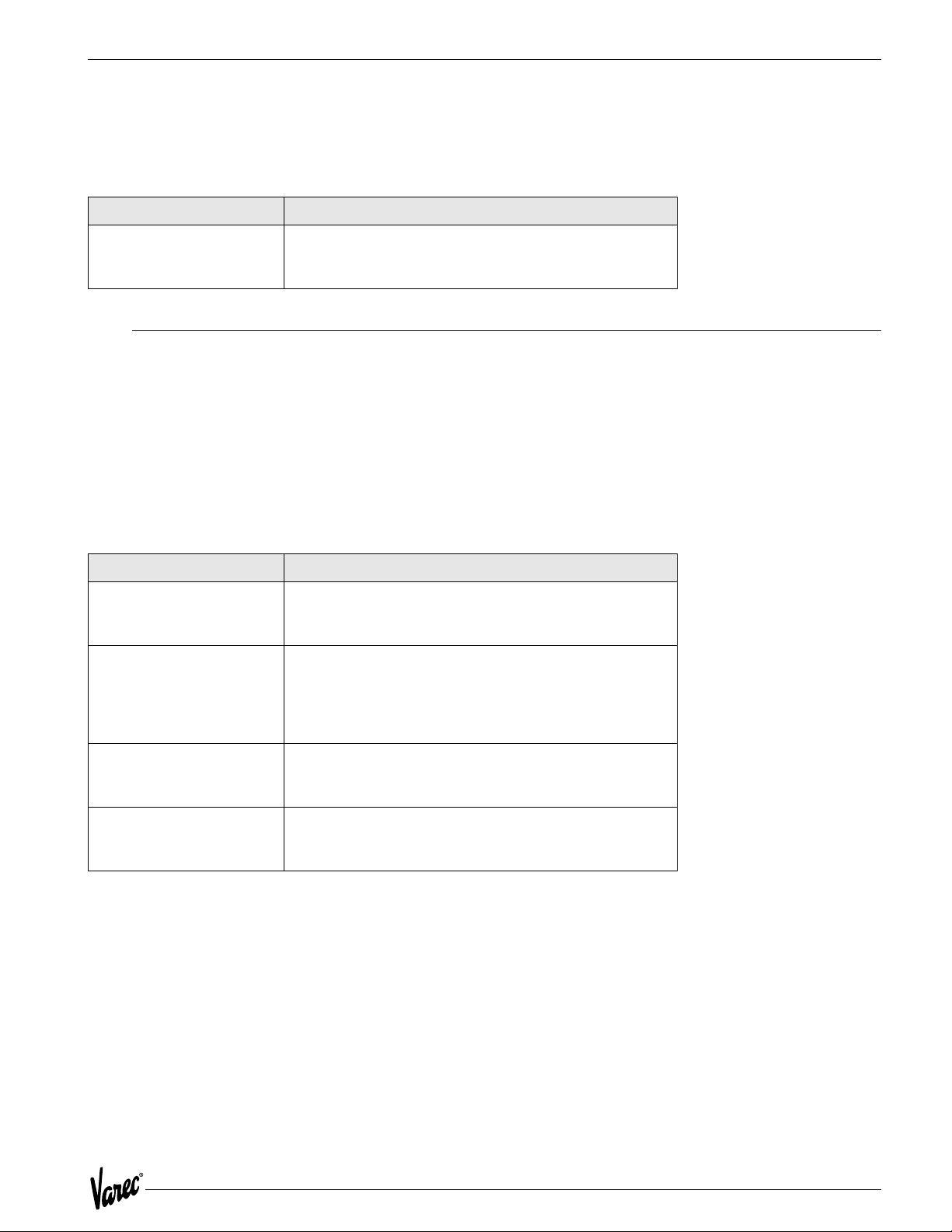
4.4 ATT Status Conditions
The ATT provides the following general status condition.
Status Condition Description
FIELD CONFIG MODIFIED
Set when the configuration is modified from the Model
1200. This status condition will only be available to the
host computer and will not appear on the Model 1200.
4.5 A TT Configuration Error Checking
The ATT performs extensive integrity checking on the configuration data before it uses it for calculations. If a
configuration error is detected, the ATT will generate a CONFIG ERROR status. The status is displayed on the local
display, available to the Model 1200 via the Diagnostic/Status Menu, and available to the host computer. To help
isolate the type configuration error, the operator can look at CFG ERROR TYPE item under the Diagnostic/Status Menu.
The following are the type of configuration errors and what causes them. The word 'Invalid' implies that the ATT was
expecting one of a certain set of values to be assigned to a particular configuration option. This may have been caused
by a sudden power outage, a failure in the EEPROM memory, or an invalid configuration received from a host computer.
Error Message Description
SCALING VAL
ALM SP
Check the level and temperature scaling values under
the Host Comm Menu. The ATT insures that the
minimum value is smaller than the maximum value.
Check the four level and four temperature alarm
setpoints under the Config Menu. The ATT insures that
the critical high setpoint is higher than the advisory
high, the advisory high is higher than the advisory low,
and the advisory low is higher than the critical low.
ALM DBAND
SENS CFG
Check the level and temperature deadbands under the
Config Menu. The ATT insures that they are a positive
value.
Check the Level Type and Temperature Type under the
Config Menu. The ATT insures that they have valid
values.
29
Page 40

Maintenance and Troubleshooting Tank Gauge Transmitter
4.6 Model 1200 Error Messages
The following error messages can be encountered while using the Model 1200.
Error Message Description
INVALID ANSWER
The operator was expected to enter either a 'Y' for yes
or an 'N' for no and something different was entered.
INVALID FLOAT The operator entered an invalid floating point number. The
INVALID INPUT
proper format for floating point entry is
[spaces][sign]number['.'][number]['E'][sign][number]
where the fields surrounded by brackets([]) are optional.
Leading spaces are permitted, however spaces within the
number are not allowed. A maximum number of 15 characters
is allowed. The exponent (value after 'E') cannot be larger than
30 nor less than -30.
The operator was given a choice of two different
characters to enter and something else was entered.
INVALID NUMBER
NEGATIVE NUMBER
The operator entered an invalid number.
The operator entered a negative number when asked for
a positive float number.
NOT ALTERABLE
The operator attempted to alter a Command,
Informational, or Menu Item using the F3 (alter) key.
NOT IN ALTER MODE
The operator attempted to alter a Configuration Item
using the F3 (alter) key while in the Display Mode.
TOO MANY CHARACTERS
The operator attempted to enter more than the allowed
number of characters.
NUMBER TOO LARGE
The operator entered a number that is beyond the limits
of a particular Configuration Item.
4.7 Host Communication Loopback Tests
Communications between a host computer and several field devices, such as the ATT, usually occurs on a single set
of wires. Each device is individually addressable by the host computer.
The ATT contains special circuitry that reduces the chance of one ATT shorting the host communication lines. The
circuitry allows the ATT to disconnect itself from the communication line and perform a loop-back test.
The test is performed automatically on power-up. It is also performed periodically if communication is no longer
detected from the host computer.
If the ATT fails its local loop-back test, it will generate a 'Bad Comm Board' status and disconnect itself from the host
communication lines. It will remain disconnected until it can pass its internal loop-back test.
30 Installation and Operations Manual
Page 41
4000 Specifications
5 Specifications
5.1 Specifications and Physical Characteristics
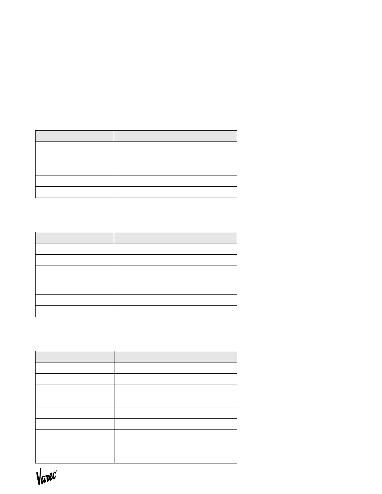
The following specifications apply to the Varec Model 4000 Advanced Technology Transmitter assembly over the
operating temperature range.
5.1.1 Environmental
Item Specification
o
Temperature -40
Humidity -0 to 95% (non-condensing)
Transient Lightning Meets ANSII/IEEE C62.41
EMI Meets SAMA 33.1C
Vibration Shock Meets SAMA PMC 31.1
C to +85 oC (operating)
5.1.2 Physical
Item Specification
Housing Aluminum NEMA 4X, NEMA 7
Bolts Plated carbon steel per ASTM A449, Grade 2
Paint Epoxy-polyester
Dimensions 190.5 mm (7.5") diameter x 203.2 mm (8.0")
Net Weight 1.8 kg (4 LB)
Shipping Weight 3.6 kg (8 LB)
deep
5.1.3 Input Power
Item Specification
4000 M4FMO 48 - 65 VDC
4000 GMFMO 24 - 65 VDC
4000 48 FMO 24 - 65 VDC
4000 TIFMO 60 - 65 VAC
4000 GEFMO 45 - 55 VAC
4000 LJFMO 48 - 65 VDC
4000 MXFMO 48 - 65 VDC
4000 WBFMO 48 - 65 VDC
5 mA typical at 48 VDC 250 mW, Nominal
31
Page 42

Specifications Tank Gauge Transmitter
5.1.4 Level Measurement
Item Description
Resolution 0.04 in (1.0 mm)
Counter Level Range +/-128 ft (39 M)
Count Verification Check Disk
Level Data Type Absolute with Calibrated Level
Calibration Level Software Configured
Units of Measure Software Configured
Direction of Rotation Software Configured
Rotational Speed 1000 RPM Maximum
Gear Ratio 1:1 - No Gears
Communications Check Depends on communication system
Count Error Status Flag to System
Battery Low Status Flag to System
Battery Operation 336 Hours (with automatic shut-off after 24)
Battery Shelf Life 10 Years
32 Installation and Operations Manual
Page 43
4000 Specifications
5.2 Safety Agency Approvals
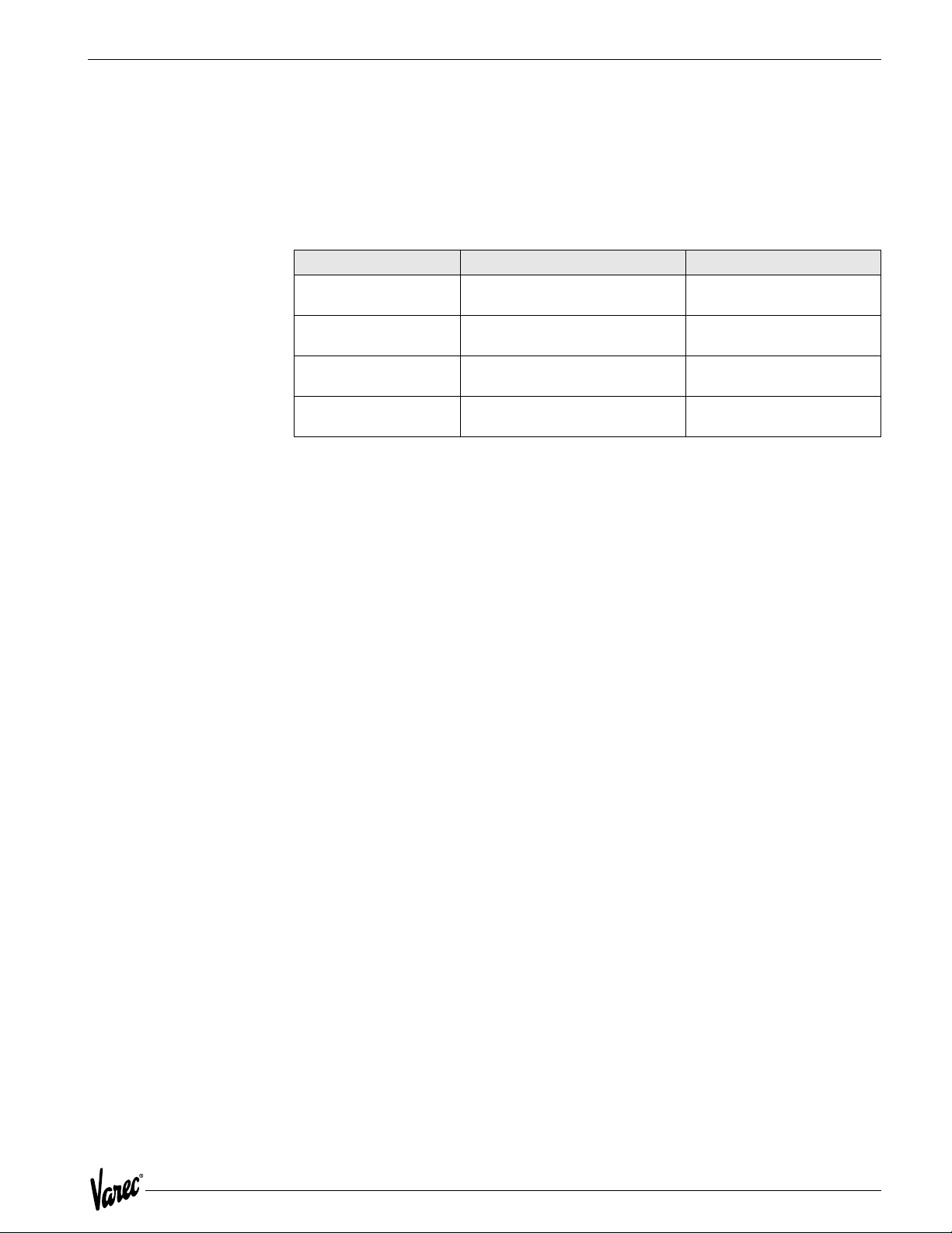
5.2.1 Explosion Proof
The HART Level Encoder is designed to meet the following safety agency approval requirements for explosion proof
installations:
Agency Acronym Agency Requirement
(FM) Factory Manual Approval StandardClass
3600, 3615, 810
(CSA) Canadian Standards Association Standard C22.2No. 0.0, 0.2,
(BASEEFA) CENELEC CENELEC StandardEN50014,
(UK) British StandardBS5501, Part
5.2.2 Intrinsic Safety
0.4, 0.5, 14, 30, 94, 142
EN50018
1, 5
The ATT is not an intrinsically safe device and must not be opened or wired while power is applied.
33
Page 44
Specifications Tank Gauge Transmitter
5.3 Major System Assemblies and Components
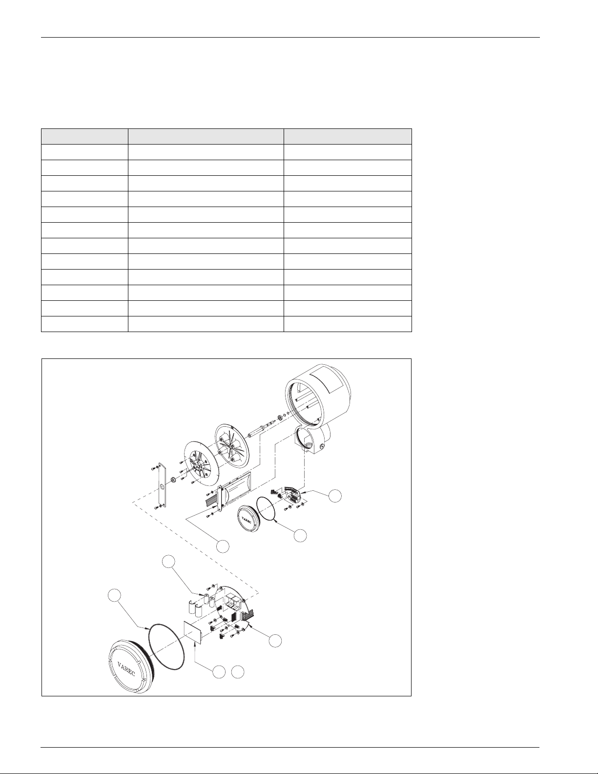
The major assemblies and components for the Model 4000 are identified in the following table and illustrated in
Figure 5-1.
Item Assembly/Component Part Number
1 Shaft/Disk Assembly 06-09478
2 Sensor Assembly 08-09220
3 CPU Assembly 08-10671
4 Batteries, quantity 2 P117-01-004
5 Terminal Board Assembly 08-10702
6 GPE Terminal Board GPE-08-11515
7 Mark/Space Communications Module 08-10674
8 EIA-485 Communications Module 08-10677
9 Mark Space Matrix 08-10680
10 Whessoe Bus GPE Communications 08-10683
11 TIWAY Communications 08-10828
12 L&J Tankway Communications 08-10909
4
12
1
3
12
2
5 -
11
Figure 5-1: ATT Major Assemblies
34 Installation and Operations Manual
Page 45
4000 Order Codes
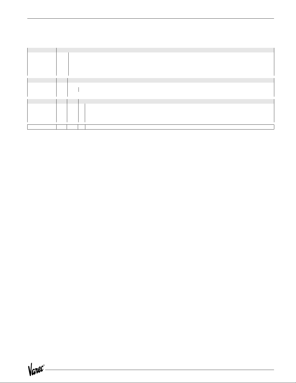
6 Order Codes
10 Communications
20 Approvals
30 Mounting
N4000 - Complete product designation
GE GPE Loop Communication
MX Mark Space Matrix (1600/1700)
TI TIWAY Communication
WB Whessoe Bus Current Loop (1315)
GM GSI Type MODBUS
CS CSA Cl.I Haz. Loc. (CAN/CSA C22.2,No. 30-M1986)
FM FM Cl.I Gr. C,D; Cl.II Gr. E, F,G Cl.II Haz. Loc. (ETL 557067)
AT DEMKO 04 ATEX 0327020 EEx d II B
0 Mounting 2500 ATG Series
1 L&J (Shand & Jurs) 92513, 92514, 92020, 92030
2 Whessoe 2006, 2026, 2036 and L&J (Shand & Jurs) 92006
3 Adapter for Sakura LT-101
35
Page 46

Order Codes Tank Gauge Transmitter
36 Installation and Operations Manual
Page 47
4000 Theory of Operation
7 Theory of Operation
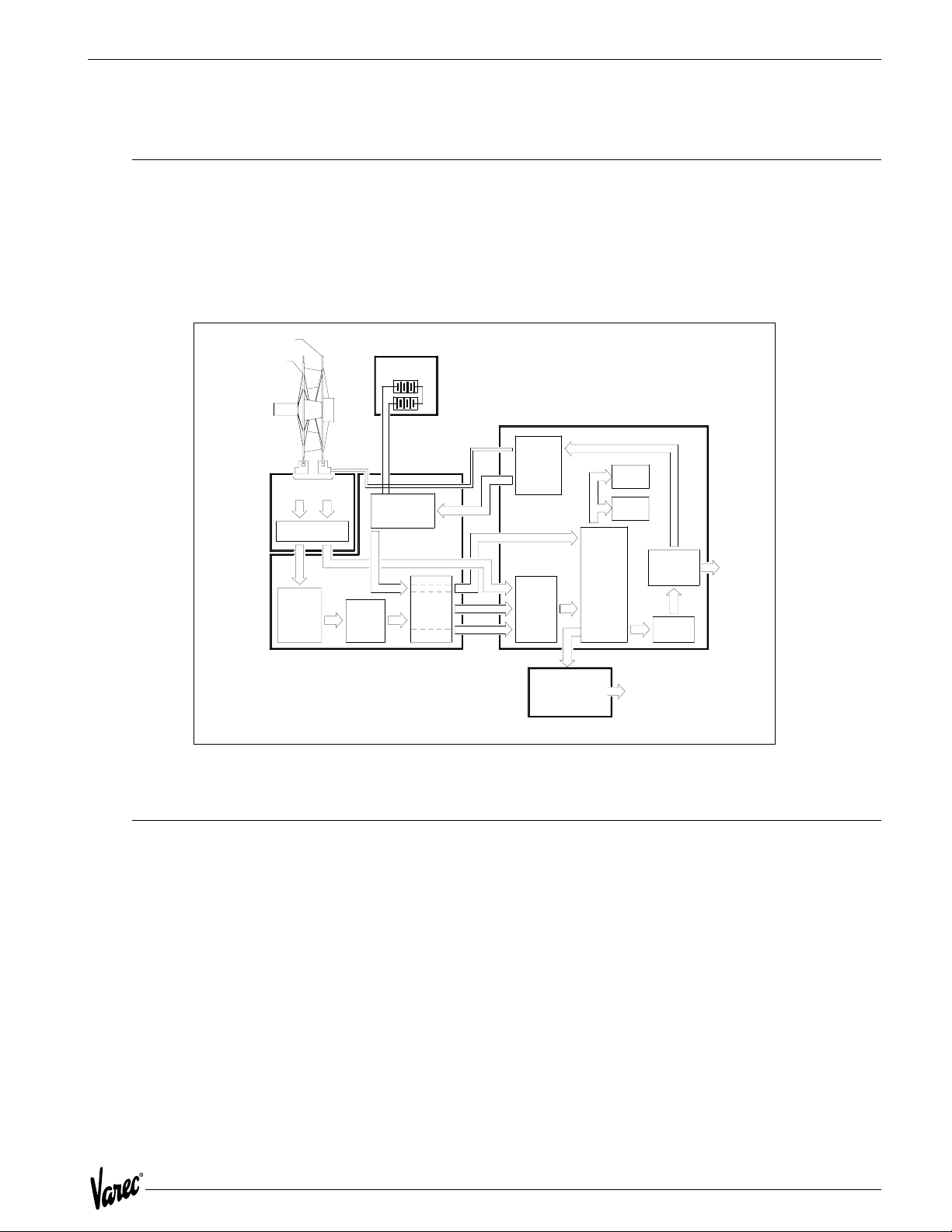
7.1 Overview
The Advanced Technology Transmitter (ATT) represents a flexible system for use in liquid level measurement and/or
other measurement applications.
The Advanced Technology Transmitter (ATT) collects measurement information from compatible devices and
transmits this information over a field communications bus.
Check disk
Board
4 slots
Dual
Optical
Sensors
Conditioning
Increment
Detector
Logic
Signal
Single
16-Bit
Binary
Up-Down
Counter
Shielded Counter Section
Batteries
3 Volt Lithium
cells
Power
Switching
Circuits
Battery and Power
Monitor
Check Disk Signal
Power-
Isolation
-
+
Down
LED Power
Count
Plug-In Communications Board
Current
Controlled
Switching
Power
Supply
I/O
Ports
Interface Module
Assembly
Mark/Space
EIA-485
TIWAY
CPU Board
8031
Micro-
Processor
64 K
EPROM
2 K
RAM
Interface
Host
To
HART Bus
Interface
Circuit
HART
Modem
L&J Tankway
Whessoe Bus Current loop
Mark Space Matrix
GPE Current loop
To ATTI
Bus
and
Handheld
Interface
Increment disk
128 slots
Shaft Input connected to
Model 2500
Sensor
Figure 7-1: ATT Block Diagram Table
7.2 CPU Board
The ATT uses the Phillips 80CL31 CPU with 64K of ROM and 8K of RAM.
The microprocessor assembly contains the CPU, power supply, and interfaces necessary to manage operation. The
power conditioning circuitry also detects a battery low condition.
The CPU monitors the count maintained in a 16-bit register. The register stores pulse information from the sensor
assembly. A ch eck disk pulse fro m the sensor a ssembly is us ed to verify the co unt at 1/4 of a disk revolut ion. The CPU
maintains an absolute level measurement based on the level calibration count provided by the ATT and the count
provided by the count register. Circuitry is provided to monitor the health of the back-up battery. When the battery
voltage indicates the battery is near the end of its life, the CPU transmits a battery low indication to the ATT.
The power supply converts input power from the ATTI bus into the voltages necessary for normal encoder operation.
The power supply limits input current from the ATTI bus to 8 mA.
37
Page 48

Theory of Operation Tank Gauge Transmitter
7.3 Status Inputs and Outputs
Status inputs and outputs are accomplished via a separate I/O Module. The ATT will communicate with the Module via
the ATTI port. The state of the inputs will be mapped into Modbus registers to allow a host computer to read them.
Control of status outputs will also be available to a host via Modbus registers. This unit is currently under development.
7.4 ATTI Communications Port
The ATTI Communication Port is a HART device compatible port. However, it does not power HART devices and is not
designed to be intrinsically safe. It is used to communicate with the 1200 Hand Held Terminal for configuration. In the
future it will support digital I/O extensions to the ATT including, 4120 Multi-Element Temperature Transmitter and
4040 Tankside display
7.5 Host Communications Interfaces
The ATT supports a plug-in host communication interface module. The following host communication modules are
supported in the initial release of the ATT.
• EIA485 Modbus
• Mark/Space
• GPE Loop Communications
• TIWAY Communications
• L&J Tankway Communications
• Varec Mark Space Matrix
• GSI Modbus
7.6 Level Measurement
The HART Level Encoder utilizes a proprietary incremental count technique for determining liquid level. Two code disks
are provided in the encoder with each disk containing a number of slots. Optical sensors for each disk detect disk
rotation by sensing the passing of these slots. The primary disk contains 128 slots and is used to calculate the actual
liquid level. The secondary or check disk contains only four slots and is used to verify or check the level from the
primary disk. The count obtained from these sensors is stored in encoder memory.
7.6.1 Back-up Battery
The encoder's back-up battery provides continuous operation during power outages. The battery is non-rechargeable
with a continuous operating lifetime of 10 days or more and a shelf life of ten years. To preserve the battery life,
automatic battery shut down occurs after 24 hours of continuous power outage. The encoder monitors the voltage of
the back-up battery and provides a battery low warning to the host in the event the battery needs replacement or has
been turned shutdown due to an extended power outage.
7.6.2 Damping
The ATT implements a damping scheme to stabilize the level and temperature in turbulent tanks. The amount of
damping is specified by a damping value in the 'DAMPING' parameter under the Config Menu. This parameter can be
entered via the Model 1200 using the Alter menu.
A damping value of 0 to 16 can be specified. A damping value of 0 implies no damping. A damping value of 16 implies
that level and temperature is averaged over 16 readings.
38 Installation and Operations Manual
Page 49

4000 Theory of Operation
7.7 Encoder Battery Backup
The ATT includes battery backup for the encoder. This allows level to be maintained across a power failure. Several
consideration are made to protect the battery from being fully discharged.
1. The battery must be physically enabled by the microprocessor. This allows the battery to be shipped connected
without being discharged.
2. Service personnel can turn the battery off. This will allow the battery to be disabled when a tank or a transmitter
is to be taken out of service for an extended period of time.
3. On-board circuitry limits the battery backup time to 24 hours. This allows battery life to be extended even if service personnel forget to disable the battery during extended power outage conditions.
The battery is automatically turned on when the ATT is calibrated with a given level.
7.8 Temperature Measurement
The ATT measures temperature directly using a high accuracy 16 bit analog to digital converter. Temperature inputs
can be either a 3-wire Copper or Platinum RTD. Optionally the temperature can be manually entered. The 4120 MultiElement Temperature transmitter can be used as a replacement to a spot temperature bulb (RTD).
7.9 Host Communication
The Modbus host interface permits the ATT to directly communicate with any distributed control system utilizing the
Gould Modbus protocol. The Modbus protocol defines two data formats, ASCII and RTU. The RTU format specifies that
all data is in binary. The ASCII format specifies that all data is in ASCII (producing messages twice as long as RTU format
messages). The ATT only supports the RTU message format.
The Modbus protocol permits a host computer to view field devices as having analog input registers, analog output
registers, digital input registers, and digital output registers. Measured parameters, configuration parameters, and
status conditions are mapped to Modbus analog and digital registers.
A non-standard Modbus floating point register extension has been defined for use by the ATT. This format extension
permits floating point data to be directly read from and written to any Modbus device. The IEEE 754 standard floating
point format is used. Each floating point register consists of four bytes.
To provide compatibility with future enhancements, data written to undefined registers are accepted and ignored. Data
read from undefined registers returns a value of zero (0).
The supported Modbus functions and exceptions are indicated in the following tables.
39
Page 50

Theory of Operation Tank Gauge Transmitter
Function Number Function
01 Read Digital Outputs
02 Read Digital Inputs
03 Read Analog Output Registers
04 Read Analog Input Registers
05 Write Single Digital Output
06 Write Single Analog Output Register
08 Loopback Test
15 Write Multiple Digital Outputs
16 Write Multiple Analog Output Registers
65 Read Floating Point Registers
66 Write Floating Point Registers
Table 7-1: Modbus Functions
Number Exception
01 Illegal Function
02 Illegal Address
03 Illegal Data
04 Busy
Table 7-2: Modbus Exception Responses
7.10 Mark/Space Host Interface
The Mark/Space interface provides compatibility with existing Mark/Space data highways. The interface operates in
one of two modes.
• Transmitter Emulation Mode
• Varec 1800 Transmitter Emulation
• Varec 1900 Transmitter Emulation
• Mark/Space Modbus Communication Mode
When operating in the 1800 or 1900 emulation mode, the ATT is compatible with all existing Varec field interfaces
such as the Tank Polling Unit (TSU) or RTU 8130.
The ATT automatically determines if it is being polled as an 1800/1900 transmitter. When polled, the ATT will respond
based on the configured emulation mode. The ATT can be configured to support the following encoding formats:
• Imperial Fractional
• Imperial Decimal
• Metric, 0-20 meter
• Metric, 0-30 meter
When emulating an 1800 or 1900, battery low status can be reported as one of the dry-contact inputs or as an invalid
level.
Note! The ATT will accept but ignore the Raise/Lower Displacer commands.
40 Installation and Operations Manual
Page 51

4000 Theory of Operation
7.11 Modbus Support over Mark/Space Host Interface
The ATT permits Modbus communications over the Mark/Space data highway. The Modbus request message is placed
into a Mark/Space message frame. The ATT processes the request message and places the Modbus reply in a Mark/
Space reply frame.
This option is only available with systems using the Model 6840 Tank Polling Unit.
7.12 Compatibility with Varec Tank Polling Unit
The Mark/Space communications provided by the ATT are compatible with the Varec Tank Polling Unit (TPU). This
permits the ATT to be multi-dropped on the same Mark/Space data highway as the Varec 1800, Varec 1900, and MFT/
HIU devices.
If the EIA485 communications interface is installed in the ATT, it can be multi-dropped on an EIA485 data highway,
RTU 8130 along with any Modbus compatible device, including the Model 6850 Field Interface Converter.
41
Page 52

Theory of Operation Tank Gauge Transmitter
42 Installation and Operations Manual
Page 53
4000 ATT Family of Products
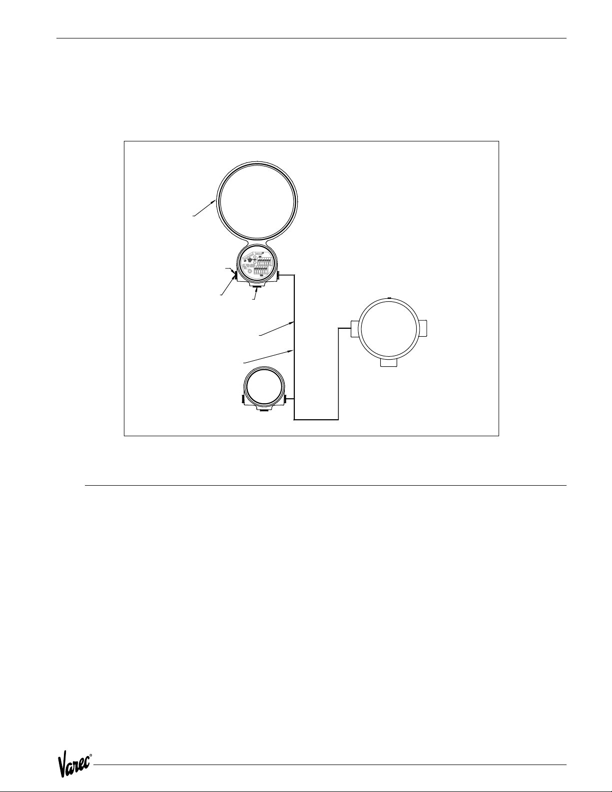
4
d
8 ATT Family of Products
The ATT product family consists of the 4000 ATT, the Model 4040 Display Unit, and the Model 4050 Digital Input/
Output Unit.
Model 4000 ATT
Model 4000
mounted to Float Gauge
24-65 Vdc for EIA-485
48-65 Vdc for Mark/Space
65 Vac for TIWAY
8-65 Vac for Whessoe Bus
Model 4050
Connection to host
computer system via:
4-Wire Mark/Space
Matrix Mark/Space
TIWAY
Whessoe Bus
GPE
L&J
Handheld Interface
connects to any unit
for system configuration
Connection to spot
temperature bulb
Three wire
ATTI Bus
Digital I/O Unit
Connection to
four digital inputs an
four digital outputs
Model 4040
Display Unit
Figure 8-1: ATT Family of Products
8.1 Model 4040 Display Unit
The Model 4040 is a four line LCD display unit. It operates connected to and is powered from the ATTI bus. The Unit
is mounted in a round explosion proof junction box with a window. Two 3/4-inch conduit entries are available.
Configuration is performed with the handheld interface. The handheld interface can be connected to any point on the
ATTI bus to communicate with the Model 4040. The user may select any of the following parameters for display on
each of the three lines.
• Level (default)
• Temperature (RTD - default, or Average)
• Status (default)
• Digital I/O Unit 4, 5 or 6
• Input 1-2-3-4
• Output 1-2-3-4
• Analog I/O Unit 7, 8 or 9
• Input 1-2-3-4
• Output 1-2-3-4
43
Page 54

ATT Family of Products Tank Gauge Transmitter
8.2 Model 4050 Digital Input/Output Unit
The Model 4050 is a digital I/O unit. It includes four digital contact closure outputs and four digital inputs. It operates
connected to and is powered from the ATTI bus. The unit is mounted in a round explosion proof junction box. Three
3/4-inch conduit entries are available.
• Primarily configured by jumpers. Three sets of jumpers are used.
• Unit address: 4 jumpers for range 0-15. Digital I/O units normally use address 4,5 or 6.
• Active state jumper for each digital output. Jumper determines if contact is N. O. or N. C.
• Default power condition for each digital output. Jumper determines if contact is open or closed when no power is
applied.
8.2.1 Digital Outputs
The use of the digital outputs is configured within the ATT using the handheld interface. Digital outputs 1 - 4 can be
configured as follows:
1. Set output as level switch:
• Set for low or high closure.
• Set level to actuate.
2. Set output for Modbus command to write.
8.2.2 Digital Inputs
Digital inputs 1 - 4, can each be read with a Modbus command.
8.2.3 Relay Specifications
The latching relays will switch 110 VAC at 1 A or 24 VDC at 2 A. The unit does not support 220/230 VAC.
44 Installation and Operations Manual
Page 55

4000 Modbus Implementation
9 Modbus Implementation
9.1 Introduction
This protocol guide explains the operation of the Modbus protocol as described in the following Modicon document:
PI-MBUS-300 Rev B (1985) implemented in the Varec Model 4000 Advanced Technology Transmitter (ATT).
9.2 Implementation
The implementation of the Modbus protocol for the ATT provides a standard form of digital communications. An effort
has been made to parallel current implementations to the greatest extent possible, so that the ATT communicates with
existing Modbus masters.
Check compatibility carefully to ensure that the ATT is properly configured for the data format expected by the host
computer. Exceptions made because of the unique requirements of the ATT application have been noted. This is no
guarantee, however, that the interpretation made here will be the same as that followed by the Modbus master.
The ATT implementation of the Modbus protocol provides for the passing of measured and calculated variables,
configuration information, and diagnostics in data registers. Data is sent in these registers as floating-point values,
integer values, numeric codes related to configuration lists, status summary words (packed bits), or individual status
flags (single bits).
One master and up to 31 ATTs may be multi-dropped on a single EIA485 communication bus.
The Modbus functions implemented in the ATT are listed in Figure 9-1 on page 46.
9.3 Configuration
The Modbus port on the ATT must be configured to establish communications. The Model 1200 Handheld Interface
allows the user to set the ATT Modbus port to match the Modbus master.
ATT addresses provide unique identification for the host. The ATT address is configurable through the Model 1200.
This address may range from 1 to 254 and must be unique. Each ATT only responds when a query has been sent to
its unique address by the host.
The Modbus protocol supports two modes of transmission, Remote Terminal Unit (RTU) or ASCII (American Standard
Code for Information Interchange). The choice between these two modes is dependent on the preference of the host.
RTU is often the preferred protocol because of its improved error detection capabilities and higher throughput. ASCII
mode uses ASCII printable characters to represent hexadecimal values. This mode of transmission requires almost
twice as many characters to pass information as does the RTU transmission mode. The ATT only supports the RTU
mode of communications.
45
Page 56

Modbus Implementation Tank Gauge Transmitter
Function
Code
01 Read Bits Read output status
02 Read Bits Read input status
03 Read Integer, Code, Status word,
04 Read Integer, Code, Status word,
05 Write Bits Force single output status
06 Write Integer, Code, Status word Preset single register
08 n/a Repeat of Loopback Message Loopback test
15 Write Bits Force multiple outputs
16 Write Integer, Code, Status word,
65 Read Floating point Read floating point registers
66 Write Floating point Write floating point registers
Function Information Type Modbus Nomenclature
Read output registers
Floating point
Read input registers
Floating point
Preset multiple registers
Floating point
Table 9-1: Modbus Functions
Note! Exception: Because the A TT does not distinguish between inputs and outputs, function codes 01 and 02 as they apply
to bits, and function codes 03 and 04 as they apply to numeric values refer to the same data registers. For example,
either function code 03 or function 04 can be used to read the integer form of the true mass variable at data address
0053.
Configuration Item Valid Entries Modbus
Modbus Address 1 to 254 No Yes
Maximum Integer Size Whole number (0 to 65,534) Yes Yes
Integer Scaling Factors Floating point number Yes Yes
Unit Selection Coding list Yes Yes
Baud Rate 300, 600, 1200, 2400,
4800, 9600
Number of Stop Bits 1 or 2 No Yes
Parity Odd, Even, None No Yes
Configurable
No Yes
Model 1200
Configurable
Table 9-2: Modbus Configuration Information
46 Installation and Operations Manual
Page 57

4000 Modbus Implementation
9.4 Functions and Data Formats
The Modbus data in the ATT is arranged in integer registers, floating point registers, and status bits. The assignments
for these registers are found at the end of this appendix.
Function codes 03, 04, 06, and 16 are used with integer registers.
Because of the multiple Modbus hosts available today, the ATT supports two floating-point data formats: a two 16bit register format and a one 32-bit register format. These two formats provide maximum system flexibility. In the
two 16-bit registers format, function codes 03 and 04 are used to read floating-point registers while function code
16 is used to write floating-point registers. In the one 32-bit register format, function code 6 5 i s u s e d t o read floatingpoint registers, while function code 66 is used to write floating-point registers.
Function codes 01, 02, 05, and 15 are used with status bits.
A complete description of all the preceding commands, except floating point, can be found in the Modicon Modbus
Protocol Reference Guide, document number PI-MBUS-300 Rev B.
9.5 Integer Registers
Integer registers are the most commonly used type of Modbus data and are supported by most Modbus hosts. In the
ATT implementation, the Modbus registers are arranged in one of the following four formats:
• Integer Data - a scaled number from 0 to the maximum Modbus integer
• Character Data - 2 ASCII characters per 16-bit register (ex. date, password)
• Coded Data - Multiple choice configuration data chosen from a coded list
• Packed Bit Data - Register form of 16 packed single bits
The integer, character, and coded data registers contain all of the information needed to configure and read process
data. Any integer register may be read with function code 03 or function code 04. These same registers may be written
one at a time with function code 06 or multiple registers can be written with function code 16.
For future compatibility, the ATT accepts reads and writes to reserved registers. Writes to reserved registers have no
effect. Reads from reserved registers return a zero (0).
Term Definition
Address User-assigned address of the slave device
Function Code Function the slave is to perform
Start Register (H) High-order data address byte of the number of registers to read
Start Register (L) Low-order data address byte of the first register to read or write
Number of Registers (H) High-order byte of the number of registers to read or write
Number of Registers (L) Low-order byte of the number of registers to read or write
or write
Byte Count Number of data bytes
Data MSB Data register's most significant byte
Data LSB Data register's least significant byte
Status Bit (H) High-order data address byte of the first bit to read or write
Status Bit (L) Low-order data address byte of the first bit to read or write
Error Check Message checksum CRC (Cyclical Redundancy Check)
47
Page 58

Modbus Implementation Tank Gauge Transmitter
Note! In all of the following communication examples, the error check value is dependent upon the mode of transmission.
9.5.1 Integer Data
The integer data is a whole number between 0 and the maximum Modbus integer (inclusive). The maximum Modbus
integer is a user-configurable variable that is a whole number between 0 and 65,535 (inclusive). The integer data must
also be scaled for each data type by entering the desired units, a minimum, and a maximum value. In order for the
integer value to be correctly interpreted, these scaling factors must match the format expected by the host system.
Scaling of the integer parameters is accomplished through floating-point registers or by using the Model 1200
Handheld Interface.
The following communication example shows the request for one register starting at register 0 (0000 Hex).
For the following example, assume:
• minimum = 1 meter
• maximum = 15 meters
• maximum Modbus integer = 65,534
Host Request
Address Function
Code
01 03 00 00 00 01 XX
ATT Response
Address Function
code
01 03 02 41 24 XX
Start RegHStart RegL# of Reg
H
Byte
Count
Data
MSB
Data
LSB
# of Reg
L
Error
Check
Error
Check
48 Installation and Operations Manual
Page 59
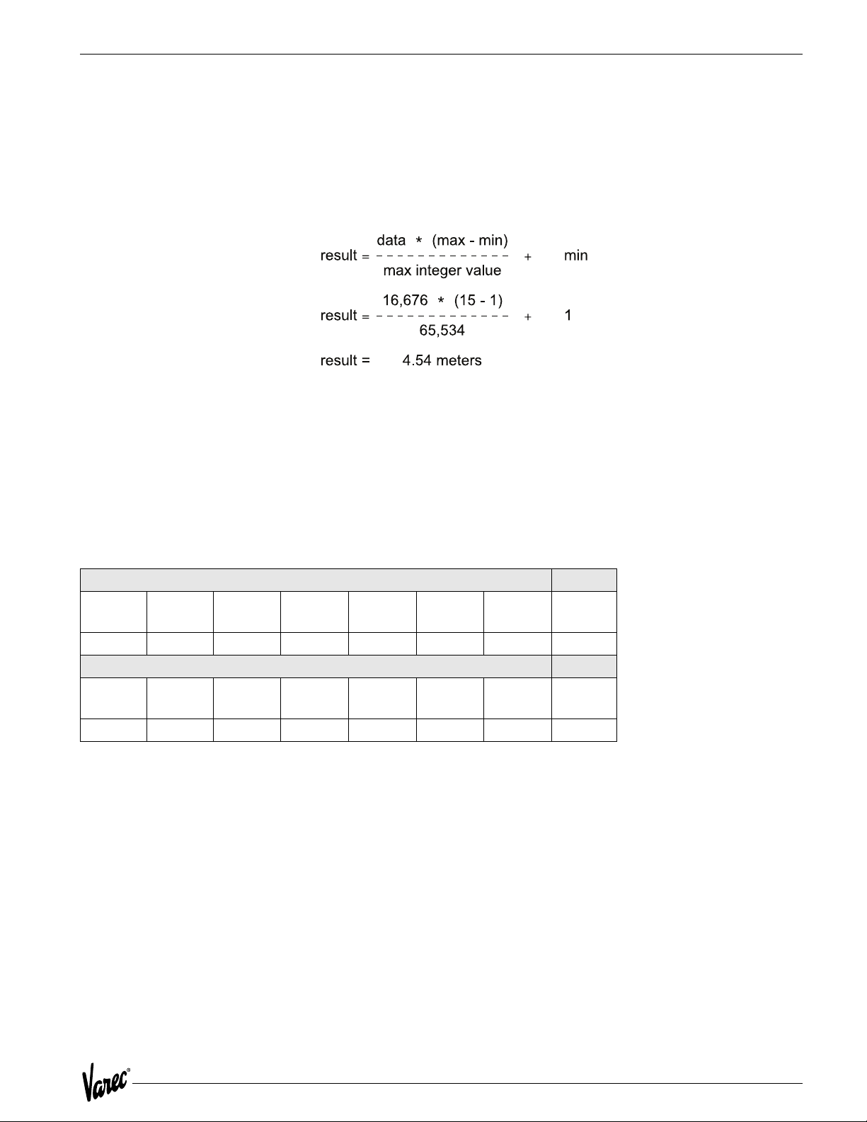
4000 Modbus Implementation
9.5.2 Integer Data
• Hexadecimal representation
• 4124Decimal equivalent: 16,676
The data returned for data address 56 is 16,676 (4124 Hex). This value must be scaled using the following formula to
give it meaning.
If a variable goes out-of-bounds (outside the minimum or maximum scale points), a value equal to the maximum
Modbus integer + 1 is returned. Writing to dynamically calculated parameters has no effect on those parameters.
9.5.3 Character Data
Character data, such as software version, are returned in registers in ASCII data format. Each Modbus register
represents two ASCII characters.
The following communication example shows the character data "ATT-" read from the ATT.
Host Request
Address Function
Code
01 03 00 1E 00 02 XX
ATT Response
Address Function
code
01 03 04 41 54 54 2D XX
• Hexadecimal representation 41 54 54 2D
• ASCII representation: ATT-
Start RegHStart RegL# of RegH# of RegLError
Check
Byte
Count
Data
MSB
Data
LSB
Data
MSB
Data
LSB
Error
Check
49
Page 60
Modbus Implementation Tank Gauge Transmitter
9.5.4 Coded Data
Coded data represents a table look-up value. Data written to these registers must be a valid table entry. Invalid data
may cause a Configuration Error to occur. The following example shows coded data at data address 20 (0014 Hex)
representing level units. The value 2 (0002 Hex) returned from the ATT corresponds to level units = FT-IN-16TH.
Host Request
Address Function
Code
01 03 00 14 00 01 XX
ATT Response
Address Function
code
01 03 02 00 02 XX
• Hexadecimal representation 0002 (decimal 2)
• Level unit table representation: FT-IN-16TH
Start RegHStart RegL# of Reg
H
Byte
Count
Data
MSB
Data
LSB
# of Reg
L
Error
Check
Error
Check
9.5.5 Packed Bit Data
Packed bits represent 16 individual status bits packed into one register. The status bits have been packed this way for
systems that prefer handling only register information. These bits may also be read or written individually using a bit
command. The bits within the packed registers are grouped by data or function type. The following communication
example of packed bits shows alarm status information at data address 5 (0005 Hex) returned by the ATT.
Host Request
Address Function
Code
01 03 00 05 00 01 XX
ATT Response
Address Function
code
01 03 02 00 01 XX
Note! Bit #0 is ON indicating a critical low level Alarm
Start RegHStart RegL# of Reg
H
Byte
Count
Data
MSB
Data
LSB
# of Reg
L
Error
Check
Error
Check
50 Installation and Operations Manual
Page 61

4000 Modbus Implementation
9.6 Floating-Point Registers
Although not part of the Modbus protocol specification, floating point numbers have been implemented using the IEEE
754 standard. Floating point numbers reduce the complexity required in scaling integer values and provide a means
to transmit numbers used by the ATT that are not easily scaled (such as the scaling factors themselves).
9.6.1 Floating-Point Data
The ATT is capable of using a two 16-bit registers format and a one 32-bit register format. Examples and descriptions
of both formats follow.
Note! Although this type of data does not require scaling, it is important that the measurement unit selected in the ATT be
the same as that expected by the host. In addition, where possible, data is available in both integer and floating-point
formats.
9.6.2 The Two 16-bit Registers Format
Function code 03 or 04 is used to read floating-point registers in this format. Function code 16 is used to write
floating-point registers in this format. An example of reading the temperature, register 102 ( 0066 Hex), in floatingpoint format from the ATT is shown as follows:
Host Request
Address Function
Code
01 03 00 66 00 02 XX
ATT Response
Address Function
code
01 03 04 42 C8 00 00 XX
Start RegHStart RegL# of RegH# of RegLError
Check
Byte
Count
Data
MSB
Data
LSB
Data
MSB
Data
LSB
Error
Check
9.6.3 Floating Point Data
• Hexadecimal representation: 42 C8 00 00
• Decimal equivalent: 100.00
Floating-point registers that are defined as reserved have zero (0) as their only legal value. A write command to a
reserved floating-point register is ignored.
51
Page 62

Modbus Implementation Tank Gauge Transmitter
9.6.4 The One 32-bit Register Format
Function code 65 (41 Hex) is used to read floating-point registers in this format. An example of a floating-point
register read is shown below with the a temperature of 100.0 degrees is being read from register 1 (0001 Hex).
Host Request
Address Function
Code
01 41 00 01 00 01 XX
ATT Response
Address Function
code
01 41 00 01 42 C8 00 00 XX
Start
Reg H
# of
Reg H
Start
RegL
# of
Reg L
# of
Reg H
Data
MSB
# of
Reg L
Data Data Data
Error
Check
LSB
Error
Check
9.6.5 Floating Point Data
• Hexadecimal representation: 42 C8 00 00
• Decimal equivalent: 100.00
Function code 66 (42 Hex) is used to write floating-point registers. An example of a floating-point register write is
shown below with the value 100.0 being written into the Advisory High Temperature Alarm Setpoint, register 12 (000C
Hex).
Host Request
Address Function
Code
01 42 00 0C 00 01 42
ATT Response
Address Function
code
01 03 02 41 XX
Start RegHStart RegL# of Reg
H
Data Data Data
C8 00 00 XX
# of Reg H# of Reg LError
Check
# of Reg
L
LSB
Data
MSB
Error
Check
9.6.6 Floating Point Data
• Hexadecimal representation: 42 C8 00 00
• Decimal equivalent: 100.00
Floating-point registers that are defined as reserved have zero (0) as their value. A write command to a reserved
floating-point register will be ignored.
52 Installation and Operations Manual
Page 63
4000 Modbus Implementation
9.7 Status Bits
In the ATT implementation, status bits contain alarms, commands, and status information. The state of a Modbus
status bit is defined as either ON (true) or OFF (false). The ON state is represented by a "1". The status bits may be read
with function code 1 or 2. They may be written one at a time with function code 5 or multiple bits may be written with
function code 15. An example of a read message for bits 2 through 6 as returned by the ATT is shows as follows.
Host Request
Address Function
Code
01 02 00 02 00 04 XX
ATT Response
Address Function
code
01 02 01 12 XX
Start RegHStart RegL# of Reg
Byte
Count
Data Error
9.7.1 Status Bit Data
H
Check
# of Reg
L
Error
Check
Binary representation 1 0010 (bits 6-2)
Bit #2: High Advisory Alarm OFF
Bit #3: High Critical Alarm ON
Bit #4: Unauthorized Mass Movement OFF
Bit #5: Standard Density Alarm OFF
Bit #6: Critical Zone Alarm ON
9.8 Exception Responses
The exception responses returned by the ATT are listed below:
Exception Response Reason
01 Illegal Function Message is not allowed
02 Illegal Data Address Data address (bit or register) requested is not defined
03 Illegal Data Value Data value being written is out of range
04 Busy During power-up
In addition, messages that are received with a parity error, checksum error, or message format error will be ignored.
53
Page 64

Modbus Implementation Tank Gauge Transmitter
9.9 Data Out of Range
When integer data calculated by the ATT is outside the minimum or maximum scale points or is otherwise out of range,
the value returned is that of the maximum Modbus integer + 1. For example, if the maximum Modbus integer is
65,534 (as used in our previous examples) the "data out of range" value is 65,535. The "data out of range" convention
does not apply to the status bits, packed status bits, character data, and coded data.
The following error conditions will also cause the ATT to return scaled integer values of maximum Modbus integer + 1.
• Off-line Mode
• Strap Error
• No CALC
• API Correction Error
• CALC Error
This permits a host to detect a serious failure without monitoring other ATT status bits.
9.10 Loopback Test
In accordance with the Modbus specification, function code 8 initiates a loopback test. The purpose of this test is to
check the communication system. It does not affect the operation of the ATT. The ATT supports only diagnostic code
00. This is a request to return query data. Upon receiving a loopback message containing this code, the ATT will echo
the message sent by the host. The entire message returned will be identical to the message transmitted by the host
field-per-field. An example of a loopback message is as follows:
Host Request
Address Function
Code
01 08 00 02 F3 26 XX
ATT Response
Address Function
code
01 08 00 00 F3 26 XX
Code HO Code LO Data Data Error
Check
Code HO Code LO Data Data Error
Check
9.11 Hardware Implementation
The ATT uses a 2-Wire EIA485 hardware interface to communicate with the Modbus master. EIA485 is a high speed
differential communications network which allows up to 32 devices to operate on one network. The ATT and Modbus
master share a twisted pair of wires to communicate.
The communication distance EIA485 can reliably travel is dependent on baud rate (communication speed), wire quality,
environmental noise, wiring configuration, and the number of multi-dropped ATTs. The recommended wire for EIA485
systems is 18-gauge or larger, shielded, twisted pairs. The shield should be earth grounded at the Modbus master
(control system or computer end). The shield at the ATT should be open. The ATT- power line acts as a common
reference tie to the Modbus master
Termination resistors of 120 Ohms are shown at each end of the communication bus to minimize reflections on the
line. Termination resistors may not be necessary at baud rates of 9600 bits per second or slower. Pull-up and pulldown resistors are also shown at the Modbus master end of the cable. These resistors minimize the affects of noise
when the lines are idle. Only one set of pull-up or pull-down resistors are required per twisted pair cable.
54 Installation and Operations Manual
Page 65

4000 Modbus Implementation
9.12 Integer Register Map
Register Number Type Description
0 Scaled Level
1 Scaled Temperature
2 Reserved
3 Reserved
4 Reserved
5 Bit Field AimStat
Bit Usage
0 CRIT LO LEVEL
1 ADV LO LEVEL
2 ADV HI LEVEL
3 CRIT HI LEVEL
4 CRIT LO TEMP
5 ADV LO TEMP
6 ADV HI TEMP
7 CRIT HI TEMP
8 HW IN 1
9 HW IN 2
10 ..15 RESERVED
6 Bit Field DiagStat
Bit Usage
0 BAD LEVEL
1 BAD TEMP
2 BAD EE
3 BAD EE CKSUM
4 BAD RAM
5 BAD EPROM
6 LOCAL MODS
7 NO CALC
8 CFG ERROR
9 CALC ERROR
10 BAD CPU BOARD
11 BAD COMM BOARD
12 LOW ENC BATT
13.15 RESERVED
7 Bit Field CmdsBit Usage
0 CANCEL ALT
1 CLR LOCAL MODS
2 RESTART
3 SAVE TO EE
4 RESERVED
5 CALIB LEVEL
6 ENC BATT OFF
7 QUICK SETUP
8.15 RESERVED
55
Page 66

Modbus Implementation Tank Gauge Transmitter
Register Number Type Description
8
9
10
11
12
13
14
15
16
17
18
19
20 Code Level Units
21 Code Temp Units
22 Code Level Type
23 Code Temp Type
24
25
26
27
28 Code Quick Setup Option
Reserved
Code
Scaled
Scaled
Scaled
Scaled
Scaled
Scaled
Scaled
Scaled
Scaled
Scaled
Scaled
Code
Code
Scaled
A/D Noise Reject: Type
0 - 60Hz
1 - 50 Hz
Crit Low Level Setpoint
Adv Low Level Setpoint
Adv High Level Setpoint
Crit High Level Setpoint
Level Deadband
Crit Low Temp Setpoint
Adv Low Temp Setpoint
Adv High Temp Setpoint
Crit High Temp Setpoint
Temp Deadband
0 - METERS
1 - FEET
2 - FT-IN-16TH
0 - C
1 - F
2 - K
1 - FORWARD
2 - REVERSE
0 - NONE
1 - COPPER RTD
2 - PLATINUM RTD
Manual Temperature
Max Integer Value
Damping Value
Calibration Level
0 - NONE
1 - ENG FRAC 1800
2 - ENG DEC 1800
3 - 0 TO 20 M 1800
4 - 0 TO 30M 1800
5 - ENG FRAC 1900
6 - ENG DEC 1900
7 - 0 TO 20 M 1900
8 - 0 TO 30M 1900
9 - METRIC Modbus
10 - IMPERIAL Modbus
56 Installation and Operations Manual
Page 67

4000 Modbus Implementation
Register Number Type Description
29
30
31
32
33
34..99
100
102
104
106
108
110
112
114
116
118
120
122
124
126
128
130
132
134
136
138
140
142
144...199
200
202
204
206
208
210
Reserved
ASCII
ASCII
ASCII
ASCII
Reserved
Float
Float
Float
Reserved Float
Reserved Float
Float
Float
Float
Float
Float
Float
Float
Float
Float
Float
Float
Float
Float
Float
Reserved Float
Float
Float
Reserved
Float
Float
Float
Reserved Float
Reserved Float
Bit Field
Sw Ver[0-1] AT
Sw Ver[2-3] T-
Sw Ver[4-5]
Sw Ver[6-7]
Level
Temp
RTD Resist
Crit Low Level
Adv Low Level
Adv High Level
Crit High Level
Level Deadband
Crit Low Temp
Adv Low Temp
Adv High Temp
Crit High Level
Temp Deadband
Min Level
Max Level
Min Temp
Max Temp
Man Temp
Calib Level
Level
Temp
RTD Resist
AlmStat
211 Bit Field DiagStat
212 Reserved Reserved
213
214
215 Code Level Units
216 Code Temp Units
217 Reserved Reserved
218
219
220 Code Level Type
221 Code Temp Type
222 Reserved Reserved
Reserved
Reserved
Reserved
Reserved
57
Page 68

Modbus Implementation Tank Gauge Transmitter
Register Number Type Description
223
224
225
226
227 Reserved Reserved
228
229
230
232
234
236
238
240
242
244
246
248
250
252
254
256
258
260
Reserved
Reserved
Code
Code
Reserved
Reserved
Float
Float
Float
Float
Float
Float
Float
Float
Float
Float
Float
Float
Float
Float
Reserved Float
Float
Damping Value
A/D Noise Reject: Type
Crit Low Level
Adv Low Level
Adv High Level
Crit High Level
Level Deadband
Crit Low Temp
Adv Low Temp
Adv High Temp
Crit High Level
Temp Deadband
Min Level
Max Level
Min Temp
Max Temp
Man Temp
58 Installation and Operations Manual
Page 69
4000 Modbus Implementation
9.13 Floating Point Register Map
Register Number Description
01
23
45
67
89
10 11
12 13
14 15
16 17
18 19
20 21
Level Temp
RTD Resist Reserved
Reserved Crit Low Level
Adv Low Level Adv High Level
Crit High Level Level Deadband
Crit Low Temp Adv Low Temp
Adv High Temp Crit High Level
Temp Deadband Min Level
Max Level Min Temp
Max Temp Reserved
Man Temp Calib Level
9.14 Status Bit Register Map
Register Number Description
0..15 16..31
32..47 AlmStat
Diag Stat Cmds
59
Page 70

Modbus Implementation Tank Gauge Transmitter
60 Installation and Operations Manual
Page 71

4000 Optional Interfaces
10 Optional Interfaces
Our intent with these optional interfaces is enabling the ATT to coexist along side older VAREC style and competitor
gauging systems and transmitters. This allows the user upward migration to modern gauging systems such as the RS485 signal interface utilizing the MODBUS register set protocol. When ready to migrate to modern systems, a simple
exchange of the ATT communications module is required.
10.1 4000TIFMO
This option is compatible along side TIWAY™ transmitters. Although the ATT can coexist along side all of the TYWAY™
transmitters, the communication option is restricted to the HDLC Link Level Protocol, utilizing IT111 primitives. The
ATT is also compatible "user selectable" with an earlier version of the TYWAY™ protocol "CIM".
The ATT has user selectable configuration jumpers to apply 120-ohm termination in case maximum baud rates and
wiring distances are implemented.
This ATT option is compatible to utilize the companion products Model 4040 Tank side Display and the Model 4050,
4 channel Digital Input and outputs.
10.2 4000GEFMO
This option is compatible along side GSI / L&J transmitters. Although the ATT can coexist along side any current loop
mode transmitters, the communication option is restricted to the GPE Level Protocol format. This format utilizes what
we refer to as short and long data responses regarding level, temperature, and status. Because of the nature of this
protocol the temperature range of the RTD is limited to -200ºC to +200º C.
10.3 4000LJFMO
This option can co-exist with L&J Tankway™ Host gauging system and `transmitters. Basically it is a signal format
similar to RS-232, however signal voltage levels are in the 0 to 35 VDC range. Basic user selectable baud rate, stop
and parity bits. Transmitter address is selectable between 1 and 127; protocol is simple in nature of 2 bytes up and 2
bytes back. Response data consist of product level and temperature, encoder gray code and 2 status bits for error
checking and data validity.
10.4 4000MXFMO
This option can co-exist along side VAREC style matrix transmitters. As implied a transmitter is selected actively by
either the 48-volt or the common line in the matrix. When selected 3 milliseconds later the transmitter sends the level
data over the Mark Space data lines. This is refereed to as hard wire logic, which occurs only once when selected, it is
as if the transmitter is asleep only to wake up send data and go back to sleep. There are no communications
parameters to select because only 1 transmitter can be triggered in the matrix at one given time.
61
Page 72

Optional Interfaces Tank Gauge Transmitter
10.5 4000WBFMO
This option can co-exist along side Whessoe Bus™ transmitters, the signal format is a current loop style transmission
signal. Transmitter is user selectable between 1 and 127 with basic baud rates stop and parity bits. The protocol is
referred to as Whessmatic 550, which was widely used by the UK for their Intelligent Tang gauging systems. The ATT
meets and exceeds the requirements of the Whessmatic 550 format because of its redundant dual port capabilities,
and the bipolar signal circuitry design. The advanced circuitry allows the ATT to communicate without error at 9600
baud through 2 data ports simultaneously. A typical transmitter using current loop signal format nominally
communicates at 300 to 1200 baud at maximum.
10.6 4000GMFMO
Basically this is identical to the standard release of the 400048FMO, a MODBUS protocol device communicating over
RS-485 data lines. GSI, a tank gauging systems manufacturer has re-mapped level and temperature integer registers
to non-standard MODBUS locations. This version ATT allows it to co-exist along side GSI transmitters and gauging
systems with response data as expected.
62 Installation and Operations Manual
Page 73

4000
Glossary
Adv Hi Level
Advisory High Level alarm set point. When the product level exceeds this point an advisory alarm will be generated.
Adv Hi Temp
Advisory High Temperature alarm set point. When the product temperature exceeds this point an advisory alarm will
be generated.
Adv Lo Level
Advisory Low Level alarm set point. When the product level drops below this point an advisory alarm will be generated.
Adv Lo Temp
Advisory Low Temperature alarm set point. When the product temperature drops below this point an advisory alarm
will be generated.
Adv Rtd Level
Advisory Resistive Temperature Device Level. Height of the RTD in the tank. An alarm is generated when the level goes
below this level (temperature measurements can no longer be made).
Advisory Alarms
Process alarms intended to act as caution indicators providing users advanced warnings of unusual situations.
ATT
Varec Model 4000 Advanced Technology Transmitter.
ATTI Bus
Unpowered, non-intrinsically safe, HART compatible communication bus used on ATT.
Baud Rate
A communications measure of serial data transmission rate typically in bits per second. Normal baud rates for RS-232
interfaces are 300, 1200, 2400, 4800, 9600, 19200. The higher the baud rate, the faster the data transfer occurs
across the data line.
Comm Port
Communication Port. An access point for data entry or exit.
Crit Hi Level
Critical High Level alarm set point. When the product level exceeds this point a critical alarm is generated.
Crit Hi Temp
Critical High Temperature alarm set point. When the product temperature exceeds this point a critical alarm is
generated.
Crit Lo Level
Critical Low Level alarm set point. When the product level drops below this point a critical alarm is generated.
Crit Lo Temp
Critical Low Temperature alarm set point. When the product temperature drops below this point a critical alarm is
generated.
o
C
o
Celsius. A unit of measure for temperature readings. 0
C is the freezing point for water, 100 oC is the boiling point
of water.
63
Page 74

Tank Gauge Transmitter
DBAND
Deadband.
ft-in-16
Feet-inches-1/16 of an inch. Imperial fractional measurement.
oF
Fahrenheit. A unit of measure for temperature readings. 0
water, 212
o
F is the boiling point of water.
o
C = 32 oF. A temperature of 32 oF is the freezing point of
Host
A tank data acquisition system responsible for collecting and processing information from a number of subordinate
devices.
IEEE
Institute of Electrical and Electronic Engineers. A trade organization that provides publications, educational
information, and standards that are widely used.
IEEE 754
A floating point data format.
oK
Kelvin. A unit of measure for temperature readings typically applied to the measurement of liquefied gases. 0
273.16
o
K. The freezing point of water is 273.16 oK, the boiling point is 373.16 oK.
Level Dband
Level Deadband. The band that a level alarm must clear before the alarm is reset.
Level
Level of product in a tank.
Manual Temp
A product temperature specified and entered by the user instead of being obtained from a sensor.
MHz
Megahertz, also called megacycles. One million electronic cycles per second, a unit of electronic frequency.
Parity
A setup parameter used with serial data communications.
RTD
Resistive Temperature Device. A metal probe used to measure temperature.
Serial Ports
A hardware interface used for serial data communications.
o
C =
Stop Bits
A setup parameter for serial data communication.
Temp Dband
Temperature Deadband. The band that a temperature alarm must clear before the alarm is reset.
Temp
Temperature.
64 Installation and Operations Manual
Page 75

4000
TSU
Tank Polling Unit. A Varec interface unit that allows a host computer to interface to Varec Mark/Space, Remote
Selector, IFU, and Matrix field interfaces.
65
Page 76

Tank Gauge Transmitter
66 Installation and Operations Manual
Page 77

4000
NOTES
67
Page 78

Your official representative
Your offical representative
www.varec.com
5834 Peachtree Corners East, Norcross (Atlanta), GA 30092 USA
© 2004 Varec, Inc. All Rights Reserved. This document is for information purposes only. Varec, Inc. makes no warranties, express or implied, in this summary.
The names of actual companies and products mentioned herien may be the trademarks of their respective owners.
Tel: +1 (770) 447-9202 Fax: +1 (770) 662-8939
Varec, Inc.
 Loading...